EP3957363B1 - Système de thérapie par capture de neutrons - Google Patents
Système de thérapie par capture de neutrons Download PDFInfo
- Publication number
- EP3957363B1 EP3957363B1 EP20791847.5A EP20791847A EP3957363B1 EP 3957363 B1 EP3957363 B1 EP 3957363B1 EP 20791847 A EP20791847 A EP 20791847A EP 3957363 B1 EP3957363 B1 EP 3957363B1
- Authority
- EP
- European Patent Office
- Prior art keywords
- wall
- neutron
- accommodating unit
- frame
- therapy system
- Prior art date
- Legal status (The legal status is an assumption and is not a legal conclusion. Google has not performed a legal analysis and makes no representation as to the accuracy of the status listed.)
- Active
Links
Images


Classifications
-
- A—HUMAN NECESSITIES
- A61—MEDICAL OR VETERINARY SCIENCE; HYGIENE
- A61N—ELECTROTHERAPY; MAGNETOTHERAPY; RADIATION THERAPY; ULTRASOUND THERAPY
- A61N5/00—Radiation therapy
- A61N5/10—X-ray therapy; Gamma-ray therapy; Particle-irradiation therapy
- A61N5/1077—Beam delivery systems
-
- A—HUMAN NECESSITIES
- A61—MEDICAL OR VETERINARY SCIENCE; HYGIENE
- A61N—ELECTROTHERAPY; MAGNETOTHERAPY; RADIATION THERAPY; ULTRASOUND THERAPY
- A61N5/00—Radiation therapy
- A61N5/10—X-ray therapy; Gamma-ray therapy; Particle-irradiation therapy
-
- A—HUMAN NECESSITIES
- A61—MEDICAL OR VETERINARY SCIENCE; HYGIENE
- A61N—ELECTROTHERAPY; MAGNETOTHERAPY; RADIATION THERAPY; ULTRASOUND THERAPY
- A61N5/00—Radiation therapy
- A61N5/10—X-ray therapy; Gamma-ray therapy; Particle-irradiation therapy
- A61N5/1048—Monitoring, verifying, controlling systems and methods
-
- A—HUMAN NECESSITIES
- A61—MEDICAL OR VETERINARY SCIENCE; HYGIENE
- A61N—ELECTROTHERAPY; MAGNETOTHERAPY; RADIATION THERAPY; ULTRASOUND THERAPY
- A61N5/00—Radiation therapy
- A61N5/10—X-ray therapy; Gamma-ray therapy; Particle-irradiation therapy
- A61N5/1048—Monitoring, verifying, controlling systems and methods
- A61N5/1064—Monitoring, verifying, controlling systems and methods for adjusting radiation treatment in response to monitoring
- A61N5/1065—Beam adjustment
-
- A—HUMAN NECESSITIES
- A61—MEDICAL OR VETERINARY SCIENCE; HYGIENE
- A61N—ELECTROTHERAPY; MAGNETOTHERAPY; RADIATION THERAPY; ULTRASOUND THERAPY
- A61N5/00—Radiation therapy
- A61N5/10—X-ray therapy; Gamma-ray therapy; Particle-irradiation therapy
- A61N5/1077—Beam delivery systems
- A61N5/1078—Fixed beam systems
-
- G—PHYSICS
- G21—NUCLEAR PHYSICS; NUCLEAR ENGINEERING
- G21G—CONVERSION OF CHEMICAL ELEMENTS; RADIOACTIVE SOURCES
- G21G4/00—Radioactive sources
- G21G4/02—Neutron sources
-
- G—PHYSICS
- G21—NUCLEAR PHYSICS; NUCLEAR ENGINEERING
- G21K—HANDLING OF PARTICLES OR IONISING RADIATION NOT OTHERWISE PROVIDED FOR; IRRADIATION DEVICES; GAMMA RAY OR X-RAY MICROSCOPES
- G21K1/00—Arrangements for handling particles or ionising radiation, e.g. focusing or moderating
- G21K1/02—Arrangements for handling particles or ionising radiation, e.g. focusing or moderating using diaphragms, collimators
-
- G—PHYSICS
- G21—NUCLEAR PHYSICS; NUCLEAR ENGINEERING
- G21K—HANDLING OF PARTICLES OR IONISING RADIATION NOT OTHERWISE PROVIDED FOR; IRRADIATION DEVICES; GAMMA RAY OR X-RAY MICROSCOPES
- G21K5/00—Irradiation devices
- G21K5/02—Irradiation devices having no beam-forming means
-
- A—HUMAN NECESSITIES
- A61—MEDICAL OR VETERINARY SCIENCE; HYGIENE
- A61N—ELECTROTHERAPY; MAGNETOTHERAPY; RADIATION THERAPY; ULTRASOUND THERAPY
- A61N5/00—Radiation therapy
- A61N5/10—X-ray therapy; Gamma-ray therapy; Particle-irradiation therapy
- A61N2005/1085—X-ray therapy; Gamma-ray therapy; Particle-irradiation therapy characterised by the type of particles applied to the patient
- A61N2005/1087—Ions; Protons
-
- A—HUMAN NECESSITIES
- A61—MEDICAL OR VETERINARY SCIENCE; HYGIENE
- A61N—ELECTROTHERAPY; MAGNETOTHERAPY; RADIATION THERAPY; ULTRASOUND THERAPY
- A61N5/00—Radiation therapy
- A61N5/10—X-ray therapy; Gamma-ray therapy; Particle-irradiation therapy
- A61N2005/1085—X-ray therapy; Gamma-ray therapy; Particle-irradiation therapy characterised by the type of particles applied to the patient
- A61N2005/109—Neutrons
-
- A—HUMAN NECESSITIES
- A61—MEDICAL OR VETERINARY SCIENCE; HYGIENE
- A61N—ELECTROTHERAPY; MAGNETOTHERAPY; RADIATION THERAPY; ULTRASOUND THERAPY
- A61N5/00—Radiation therapy
- A61N5/10—X-ray therapy; Gamma-ray therapy; Particle-irradiation therapy
- A61N2005/1092—Details
-
- A—HUMAN NECESSITIES
- A61—MEDICAL OR VETERINARY SCIENCE; HYGIENE
- A61N—ELECTROTHERAPY; MAGNETOTHERAPY; RADIATION THERAPY; ULTRASOUND THERAPY
- A61N5/00—Radiation therapy
- A61N5/10—X-ray therapy; Gamma-ray therapy; Particle-irradiation therapy
- A61N2005/1092—Details
- A61N2005/1094—Shielding, protecting against radiation
-
- A—HUMAN NECESSITIES
- A61—MEDICAL OR VETERINARY SCIENCE; HYGIENE
- A61N—ELECTROTHERAPY; MAGNETOTHERAPY; RADIATION THERAPY; ULTRASOUND THERAPY
- A61N5/00—Radiation therapy
- A61N5/10—X-ray therapy; Gamma-ray therapy; Particle-irradiation therapy
- A61N2005/1092—Details
- A61N2005/1095—Elements inserted into the radiation path within the system, e.g. filters or wedges
Definitions
- the present disclosure relates to a radiation irradiation system, and in particular to a neutron capture therapy system.
- radiotherapy As atomics moves ahead, such radiotherapy as Cobalt-60, linear accelerators and electron beams has been one of major means to cancer therapy.
- conventional photon or electron therapy has been undergone physical restrictions of radioactive rays; for example, many normal tissues on a beam path will be damaged as tumor cells are destroyed.
- sensitivity of tumor cells to the radioactive rays differs greatly, so in most cases, conventional radiotherapy falls short of treatment effectiveness on radioresistant malignant tumors (such as glioblastoma multiforme and melanoma).
- BNCT boron neutron capture therapy
- BNCT Boron Neutron Capture Therapy
- B-10-containing pharmaceuticals have high neutron capture cross section and produces 4 He and 7 Li heavy charged particles through 10 B(n, ⁇ ) 7 Li neutron capture and nuclear fission reaction.
- FIGS. 1 and 2 a schematic drawing of BNCT and a nuclear reaction formula of 10 B (n, ⁇ ) 7 Li neutron capture are shown, the two charged particles, with average energy at about 2.33MeV, are of high linear energy transfer (LET) and short-range characteristics.
- LET linear energy transfer
- LET and range of the alpha particle are 150keV/micrometer and 8 micrometers respectively while those of the heavy charged particle 7 Li are 175keV/micrometer and 5 micrometers respectively, and the total range of the two particles approximately amounts to a cell size. Therefore, radiation damage to living organisms may be restricted at the cells' level. Only the tumor cells will be destroyed on the premise of having no major normal tissue damage.
- BNCT is also well known for binary cancer therapy, for its effectiveness depending on the concentration of the boronated pharmaceuticals and the number of the thermal neutrons at the tumor site.
- improvement of flux and quality of the neutron source plays a significant role in BNCT researches.
- JP 2018 161449 A discloses a neutron deceleration radiation equipment comprising a moderator body formed by a plurality of speed reducers a composed of magnesium fluoride serving as a moderator.
- the speed reducers are laminated with a plurality of first shields made of cadmium or cadmium alloy.
- a reinforcing member is provided to cover the side end faces of neutron decelerating irradiation device.
- an aspect of the present invention provides a neutron capture therapy system, including a neutron generating device and a beam shaping assembly.
- a neutron capture therapy system according to the present invention is set forth in claim 1.
- the neutron generating device includes an accelerator and a target, a charged particle beam generated through acceleration by the accelerator interacts with the target to generate neutrons, the neutrons form a neutron beam, and the neutron beam defines a main axis.
- the beam shaping assembly includes a moderator, a reflector, and a radiation shield, the moderator decelerates the neutrons generated from the target to an epithermal neutron energy region, the reflector surrounds the moderator and guides neutrons deviating from the main axis back to the main axis, to improve intensity of an epithermal neutron beam, and the radiation shield is used for shielding leaking neutrons and photons, to reduce a dose of a normal tissue not exposed to irradiation; and the beam shaping assembly further includes a frame accommodating the moderator. The frame positions and supports the moderator, so that flux and quality of the neutron source can be improved.
- the moderator is adjustable, and the frame includes a positioning member and a stopping member for fixing the moderator.
- the materials of the positioning member and stopping member are an aluminum alloy, a titanium alloy, lead-antimony alloy, cobalt-free steel, carbon fibers, PEEK, or a high molecular polymer.
- the positioning member can conveniently adjust a size of the moderator, thereby adjusting flux of the neutron beam, and after the adjustment, the stopping member can quickly and conveniently implement encapsulation of the moderator.
- the moderator includes a basic part and a supplementary part, a material of the basic part is different from a material of the supplementary part, the frame forms at least one accommodating unit, the accommodating unit includes a first accommodating unit and a second accommodating unit that are adjacent to each other, the basic part is accommodated in the first accommodating unit and is tiled and adjustable, when a number of tiles of the basic part is reduced, the positioning member is disposed inside the first accommodating unit for supplementation, and the stopping member is used for fixing the basic part.
- the supplementary part can lower manufacturing costs of the moderator without exerting relatively large impact on quality of the beam.
- the positioning member and the stopping member can conveniently adjust the basic part of the moderator.
- the frame includes a main frame and a secondary frame that are detachably connected to each other, the first accommodating unit is surrounded and formed by at least a part of the main frame, and the second accommodating unit is surrounded and formed by at least a part of the main frame and at least a part of the secondary frame, the supplementary part is accommodated in the second accommodating unit, and disposition of the secondary frame facilitates replacement of the supplementary part of the moderator.
- a material of the main frame is an aluminum alloy, has relatively good mechanical properties, and after being activated by the neutrons, generates a radioactive isotope that has a short half life.
- a material of the secondary frame is a carbon fiber composite material, after being activated by the neutrons, generates a radioactive isotope that has a short half life, and brings low radiation.
- a material of the basic part includes at least one of D 2 O, Al, AlF 3 , MgF 2 , CaF 2 , LiF, Li 2 CO 3 , or Al 2 O 3 , has a cross section for principally acting with fast neutrons but hardly acting with epithermal neutrons, and has a relatively good moderating effect.
- the basic part contains Li-6, and the basic part also serves as a thermal neutron absorber.
- a material of the supplementary part includes at least one of Zn, Mg, Al, Pb, Ti, La, Zr, Bi, or C. Selecting a material that is relatively easy to obtain as the material of the supplementary part can lower manufacturing costs of the moderator while producing a specific neutron moderating effect without exerting relatively large impact on quality of the beam.
- the main frame includes a first wall, a second wall, and a first transverse plate connecting the first wall and the second wall that are sequentially disposed along a direction of the neutron beam and that are circumferentially closed surrounding the main axis, the first transverse plate extends perpendicular to the direction of the neutron beam, the first wall is used for mounting a transmitting tube of the accelerator, the second wall surrounds and forms the first accommodating unit, and a radial distance from the first wall to the main axis is less than a radial distance from the second wall to the main axis.
- the basic part of the moderator surrounds the target, so that the neutrons generated by the target can be effectively moderated in all directions, thereby further improving flux and beam quality of the neutrons.
- the main frame includes a third wall circumferentially closed surrounding a direction of the neutron beam, the radial distance from the second wall to the main axis is less than a radial distance from the third wall to the main axis, the frame further includes first and second side plates respectively disposed on two sides of the third wall along the direction of the neutron beam and connected to the third wall, and the secondary frame includes a second transverse plate disposed between the second wall and the second side plate along the direction of the neutron beam.
- the secondary frame further includes a fourth wall circumferentially closed surrounding the direction of the neutron beam and extending between the second transverse plate and the second side plate.
- the neutron capture therapy system further includes a collimator, the fourth wall forms a mounting portion and/or a beam exit of the collimator.
- the secondary frame made of carbon fibers is used in a direction of the beam exit, and compared with an aluminum alloy, the carbon fibers have a smaller activation degree, high strength and a specific moderating effect.
- the secondary frame also serves as the mounting portion of the collimator.
- the main frame further includes a radial separator disposed between the first side plate and the second transverse plate and extending from the first wall to the second wall or the third wall, the first wall, the second wall, the third wall, the first transverse plate, the second transverse plate, and the first side plate surround and form the second accommodating unit, the radial separator circumferentially divides the second accommodating unit into several sub-regions, the third wall, the fourth wall, the second transverse plate, and the second side plate surround and form a third accommodating unit, at least a part of the reflector/radiation shield is further disposed inside the second accommodating unit, and at least a part of the radiation shield is disposed inside the third accommodating unit, and materials of the first and second side plates are a lead-antimony alloy. Lead can further shield radiation, and in addition, the lead-antimony alloy has relatively high strength.
- the basic part is provided with a center hole in a first end face facing toward the first side plate, the center hole is used for accommodating the transmitting tube of the accelerator and the target, and when the basic part is filled up, a first end face of the supplementary part close to the second side plate is flush with a second end face of the basic part close to the second side plate.
- a shielding plate is disposed adjacent to the second end face of the basic part.
- the shielding plate is a lead plate. Lead can absorb gamma rays released in the moderator.
- the thickness of the shielding plate in the direction of the neutron beam is less than or equal to 5 cm, so that the neutrons passing through the moderator are not reflected.
- the positioning member When the number of tiles of the basic part is reduced, the positioning member is disposed adjacent to the shielding plate.
- the stopping member is disposed adjacent to the second transverse plate, and the stopping member is detachably connected to the main frame and/or secondary frame, to facilitate adjustment and replacement of the basic part of the moderator.
- a neutron capture therapy system including a neutron generating device and a beam shaping assembly, where neutrons generated by the neutron generating device form a neutron beam, the neutron beam defines a main axis, and the beam shaping assembly is capable of adjusting beam quality of the neutron beam, where the beam shaping assembly includes a moderator, a reflector, and a radiation shield, the moderator decelerates the neutrons generated from the neutron generating device to an epithermal neutron energy region, the reflector surrounds the moderator and guides neutrons deviating from the main axis back to the main axis, to improve intensity of an epithermal neutron beam, and the radiation shield is used for shielding leaking neutrons and photons, to reduce a dose of a normal tissue not exposed to irradiation; and the beam shaping assembly further includes a frame accommodating the moderator, and the frame includes a main frame and a secondary frame that are detachably connected to each other.
- the frame accommodating the moderator
- the frame of the beam shaping assembly of the neutron capture therapy system according to the present invention positions and supports the moderator, so that flux and quality of the neutron source can be improved.
- a neutron capture therapy system in this embodiment is preferably a boron neutron capture therapy system 100, which includes a neutron generating device 10, a beam shaping assembly 20, a collimator 30, and a treatment table 40.
- the neutron generating device 10 includes an accelerator 11 and a target T, and the accelerator 11 accelerates charged particles (such as protons, deuteron s, etc.) to generate a charged particle beam P such as a proton beam, and the charged particle beam P irradiates the target T and interacts with the target T to generate neutrons which form a neutron beam N, the neutron beam defines a main axis X, and the target T is a metal target.
- charged particles such as protons, deuteron s, etc.
- the neutron beam N direction described below with reference to the accompanying drawings does not represent the actual neutron motion direction, but the overall motion trend direction of the neutron beam N.
- Suitable nuclear reactions are always determined according to such characteristics as desired neutron yield and energy, available accelerated charged particle energy and current and materialization of the metal target, among which the most discussed two are 7 Li (p, n) 7 Be and 9 Be (p, n) 9 B and both are endothermic reaction. Their energy thresholds are 1.881MeV and 2.055MeV respectively.
- Epithermal neutrons at a keV energy level are considered ideal neutron sources for BNCT.
- the target materials may be made of other metals besides Li or Be, for example, tantalum (Ta) or tungsten (W) or their alloys.
- the accelerator 11 may be a linear accelerator, a cyclotron, a synchrotron, a synchrocyclotron.
- BNCT neutron sources that is, beams comprise neutrons and photons having energies from low to high.
- dose is calculated using a human head tissue prosthesis in order to understand dose distribution of the neutrons in the human body. The prosthesis beam quality factors are later used as design reference to the neutron beams, which is elaborated hereinafter.
- the International Atomic Energy Agency has given five suggestions on the air beam quality factors for the clinical BNCT neutron sources.
- the suggestions may be used for differentiating the neutron sources and as reference for selecting neutron production pathways and designing the beam shaping assembly, and are shown as follows:
- the epithermal neutron flux and the concentration of the boronated pharmaceuticals at the tumor site codetermine clinical therapy time. If the boronated pharmaceuticals at the tumor site are high enough in concentration, the epithermal neutron flux may be reduced. On the contrary, if the concentration of the boronated pharmaceuticals in the tumors is at a low level, it is required that the epithermal neutrons in the high epithermal neutron flux should provide enough doses to the tumors.
- the given standard on the epithermal neutron flux from IAEA is more than 10 9 epithermal neutrons per square centimeter per second. In this flux of neutron beams, therapy time may be approximately controlled shorter than an hour with the boronated pharmaceuticals. Thus, except that patients are well positioned and feel more comfortable in shorter therapy time, and limited residence time of the boronated pharmaceuticals in the tumors may be effectively utilized.
- Gamma-ray long-range penetration radiation will selectively result in dose deposit of all tissues in beam paths, so that lowering the quantity of gamma-ray is also the exclusive requirement in neutron beam design.
- Gamma-ray dose accompanied per unit epithermal neutron flux is defined as gamma-ray contamination which is suggested being less than 2*10 -13 Gy-cm 2 /n according to IAEA.
- the thermal neutrons are so fast in rate of decay and poor in penetration that they leave most of energy in skin tissue after entering the body. Except for skin tumors like melanocytoma, the thermal neutrons serve as neutron sources of BNCT, in other cases like brain tumors, the quantity of the thermal neutrons has to be lowered.
- the thermal to epithermal neutron flux ratio is recommended at lower than 0.05 in accordance with IAEA.
- the epithermal neutron current to flux ratio stands for beam direction, the higher the ratio is, the better the forward direction of the neutron beams is, and the neutron beams in the better forward direction may reduce dose surrounding the normal tissue resulted from neutron scattering. In addition, treatable depth as well as positioning posture is improved.
- the epithermal neutron current to flux ratio is better of larger than 0.7 according to IAEA.
- the prosthesis beam quality factors are deduced by virtue of the dose distribution in the tissue obtained by the prosthesis according to a dose-depth curve of the normal tissue and the tumors.
- the three parameters as follows may be used for comparing different neutron beam therapy effects.
- Tumor dose is equal to the depth of the maximum dose of the normal tissue. Dose of the tumor cells at a position behind the depth is less than the maximum dose of the normal tissue, that is, boron neutron capture loses its advantages.
- the advantage depth indicates penetrability of neutron beams. Calculated in cm, the larger the advantage depth is, the larger the treatable tumor depth is.
- the advantage depth dose rate is the tumor dose rate of the advantage depth and also equal to the maximum dose rate of the normal tissue. It may have effects on length of the therapy time as the total dose on the normal tissue is a factor capable of influencing the total dose given to the tumors. The higher it is, the shorter the irradiation time for giving a certain dose on the tumors is, calculated by cGy/mA-min.
- the average dose ratio received by the tumors and the normal tissue from the brain surface to the advantage depth is called as advantage ratio.
- the average ratio may be calculated using dose-depth curvilinear integral. The higher the advantage ratio is, the better the therapy effect of the neutron beams is.
- RBE stands for relative biological effectiveness. Since photons and neutrons express different biological effectiveness, the dose above should be multiplied with RBE of different tissues to obtain equivalent dose.
- the neutron beam N generated by the neutron generating device 10 sequentially passes through the beam shaping assembly 20 and the collimator 30 and then irradiates to the patient 200 on the treatment table 40.
- the beam shaping assembly 20 is capable of adjusting the beam quality of the neutron beam N generated by the neutron generating device 10, and the collimator 30 is provided to concentrate the neutron beam N, so that the neutron beam N has higher targeting during the treatment process.
- the beam shaping assembly 20 further includes a frame 21 and a main part 23, at least part of the main part 23 is filled within the frame 21, the frame 21 forms supporting to the main part 23, which may prevent the deformation and damage of the material and affect the target replacing and quality of the beam.
- the main part 23 includes a moderator 231, a reflector 232, a radiation shield 233.
- the neutrons generated by the neutron generating device 10 have a wide spectrum of energy, and in addition to epithermal neutrons to meet treatment needs, it is desirable to reduce other types of neutrons and photons as much as possible to avoid injury to operators or patients. Therefore, the neutrons coming out of the neutron generating device 10 need to pass through the moderator 231 to adjust the energy of fast neutrons therein to the epithermal neutron energy region.
- the moderator 231 is made of a material having a cross section for principally acting with fast neutrons but hardly acting with epithermal neutrons, such as includes at least one of D 2 O, AlF 3 , Fluental, CaF 2 , Li 2 CO 3 , MgF 2 and Al 2 O 3 .
- the reflector 232 surrounds the moderator 231, and reflects the neutrons diffused through the moderator 231 back to the neutron beam N to improve the utilization of the neutrons, and is made of a material having high neutron reflection ability, such as includes at least one of Pb and Ni.
- the radiation shield 233 is provided to shield leaking neutrons and photons so as to reduce dose of a normal tissue not exposed to irradiation.
- the material of the radiation shield 233 includes at least one of a photon shielding material and a neutron shielding material, such as a photon shielding material lead (Pb) and a neutron shielding material polyethylene (PE). It should be appreciated that the main part may have other configurations as long as the epithermal neutron beam required for treatment may be obtained.
- the target T is disposed between the accelerator 11 and the beam shaping assembly 20, and the accelerator 11 has a transmitting tube 111 that transmits the charged particle beam P. In this embodiment, the transmitting tube 111 penetrates into the beam shaping assembly 20 in the direction of the charged particle beam P, and sequentially passes through the moderator 231 and the reflector 232.
- the target T is arranged into the moderator 231 and located at the end of the transmitting tube 111 to obtain a better neutron beam quality.
- first and second cooling pipes D1 and D2 are disposed between the transmitting tube 111 and the moderator 231, and between the transmitting tube 111 and the reflector 232, and one end of the first and second cooling pipes D1, D2 is respectively connected to the cooling inlet IN (not shown in Figs) and the cooling outlet OUT (not shown in Figs) of the target T, and the other ends are connected to an external cooling source (not shown in Figs).
- the first and second cooling tubes may also be disposed into the beam shaping assembly in other ways, and may also be omitted when the target is placed outside the beam shaping assembly.
- the frame 21 includes a first wall 211 circumferentially closed surrounding the main axis X and first and second side plates 221, 222 respectively disposed on two sides of the first wall 211 along a direction of the neutron beam N and connected to the first wall 211.
- the first side plate 221 is provided with a hole 2211 for the transmitting tube 111 to pass through.
- the second side plate 222 is provided with a hole 2221 that forms a beam exit.
- An accommodating portion C of the moderator is formed among the first wall 211 and the first and second side plates 221, 222. At least a part of the reflector and/or radiation shield is also disposed inside the accommodating portion C.
- the accommodating portion C includes at least one accommodating unit C1-C3 (described in detail below).
- Each accommodating unit C1-C3 accommodates at least one of the moderator 231, the reflector 232, and the radiation shield 233.
- the at least one accommodating unit accommodates all of at least two of the moderator, the reflector, and the radiation shield or accommodates all of at least two different materials.
- the moderator 231 includes a basic part and a supplementary part, and the basic part and the supplementary part are respectively accommodated in different accommodating units. It may be understood that the first and second side plates may alternatively not be disposed, and the first wall surrounds and forms an accommodating portion.
- the frame 21 further includes a first transverse plate 223 disposed between the first and the second side plates 221, 222 in the direction of the neutron beam N, a second wall 212 circumferentially closed surrounding the main axis X and extending between the first transverse plate 223 and the first side plate 221, and a third wall 213 circumferentially closed surrounding the main axis X and extending from the first transverse plate 223 to the second side plate 222.
- the second wall 212 is radially closer to the main axis X than the third wall 213, the third wall 213 is radially located between the first wall 211 and the second wall 212, and the first transverse plate 223 extends between the second wall 212 and the third wall 213.
- An inner surface of the second wall 212 and a side wall of the hole 2211 in the first side plate 221 are on a same surface, and the second wall 212 forms a mounting portion of the transmitting tube 111, the first and second cooling tubes D1, D2, and the like. It may be understood that the first transverse plate may extend to the first wall.
- the frame 21 further includes a second transverse plate 224 disposed between the third wall 213 and the second side plate 222 in the direction of the neutron beam N, a fourth wall 214 circumferentially closed surrounding the main axis X and extending between the second transverse plate 224 and the second side plate 222, and the third transverse plate 225 disposed between the second transverse plate 224 and the second side plate 222 and adjacent to the second transverse plate 224.
- the second transverse plate 224 extends from the first wall 211 to an inner side of the third wall 213.
- the fourth wall 214 is radially located between the first wall 211 and the third wall 213, and an inner surface of the fourth wall 214 and the side wall of the hole 2221 in the second side plate 222 are on a same surface, the fourth wall 214 and the hole 2221 in the second side plate 222 jointly form a beam exit, and a hole 2251 for the neutron beam N to pass through is formed in the third transverse plate 225.
- the third wall 213 is radially located between the fourth wall 214 and an inner wall of the hole 2251 in the third transverse plate 225, and an outer wall of the third transverse plate 225 is located between an inner surface of the fourth wall 214 and an inner surface of the third wall 213.
- cross sections of the first, second, third, and fourth walls perpendicular to the direction of the main axis X are all circular rings surrounding the main axis X, and the first, second, third, and fourth walls extend parallel to the main axis X.
- the side plates and the transverse plates are all flat plates extending perpendicular to the main axis X. It may be understood that there may be other settings. For example, an extending direction is inclined to the main axis.
- the frame may further include a plurality of walls circumferentially closed surrounding the main axis X and a plurality of transverse plates disposed between the walls, and may be further used for accommodating or supporting other parts of the beam shaping assembly.
- a region that is from the first transverse plate 223 to the third transverse plate 225 in the direction of the neutron beam N and that is surrounded by the third wall 213 forms a first accommodating unit C1.
- a second accommodating unit C2 is formed among the first wall 211, the second wall 212, the third wall 213, the first side plate 221, the first transverse plate 223, and the second transverse plate 224.
- a third accommodating unit C3 is formed among the first wall 211, the fourth wall 214, the second transverse plate 224, and the second side plate 222.
- a magnesium fluoride block 241 is disposed inside the first accommodating unit C1 as the basic part of the moderator 231.
- the magnesium fluoride block 241 contains Li-6 and can also be used as a thermal neutron absorber.
- the magnesium fluoride block 241 is cylindrical as a whole and is provided with a center hole 2411 on an end face thereof facing toward the first side plate 221.
- the center hole 2411 is used for accommodating the transmitting tube 111, the first and second cooling tubes D1, D2, the target T, and the like.
- the center hole 2411 is a cylindrical hole, a side wall 2411a of the center hole and the inner surface of the second wall 212 are on a same surface.
- a radial distance L1 from the second wall 212 to the main axis X is less than a radial distance L2 from the third wall 213 to the main axis X, so that the basic part of the moderator 231 surrounds the target T. Therefore, the neutrons generated by the target T can be effectively moderated in all directions, thereby further improving flux and beam quality of the neutrons.
- a lead plate 242 is disposed between the magnesium fluoride block 241 and the third transverse plate 225. The lead plate 242 serves as a photon shield. Lead can absorb gamma rays released in the moderator.
- the thickness of the lead plate 242 in the direction of the neutron beam N is less than or equal to 5 cm, so that the neutrons passing through the moderator are not reflected. It may be understood that, there may be other settings.
- the magnesium fluoride block 241 does not contain Li-6, and instead, the thermal neutron absorber made of Li-6 is separately disposed between the magnesium fluoride block 241 and the third transverse plate 225.
- the lead plate can also be omitted.
- An aluminum alloy block 243 and a lead block 244 are disposed inside the second accommodating unit C2.
- the aluminum alloy block 243 has surfaces in contact with the second wall 212, the third wall 213, and the first transverse plate 223, so that the aluminum alloy block 243, as the supplementary part of the moderator 231, surrounds the basic part of the moderator 231 disposed inside the first accommodating unit C1.
- the aluminum alloy block 243, as the supplementary part of the moderator 231, can lower manufacturing costs of the moderator without exerting relatively large impact on quality of the beam.
- a PE block 245 in a corresponding shape is disposed inside the third accommodating unit C3.
- the radiation shield 233 includes a neutron shield and a photon shield.
- the PE block 245 serves as the neutron shield.
- the lead block 244 serves as both the reflector 232 and the photon shield. It may be understood that the PE block may further be disposed inside the second accommodating unit C2 as neutron shield.
- the magnesium fluoride block 241 is made of tiles, which is convenient for quality control and adjusting beam intensity by increasing or decreasing the number of tiles.
- the magnesium fluoride block 241 is filled up, the magnesium fluoride block 241 is flush with an end face of the aluminum alloy block 243 close to the second side plate 222, and the lead plate 242 is disposed adjacent to an end face of the magnesium fluoride block 241 close to the second side plate 222 and is in contact with the third transverse plate 225.
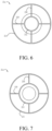
- a positioning ring 226 (shown in FIG. 5 ) is disposed between the lead plate 242 and the third transverse plate 225 for corresponding supplementation.
- positioning ring and the stopping ring may alternatively be replaced with positioning and stopping members in other forms.
- the positioning member can conveniently adjust a size of the moderator, thereby adjusting flux of the neutron beam, and after the adjustment, the stopping member can quickly and conveniently implement encapsulation of the moderator.
- PE that serves as the neutron shield may be replaced with another neutron shielding material; lead that serves as the photon shield may be replaced with another photon shielding material; lead that serves as the reflector may be replaced with another material having a strong neutron reflecting capability; magnesium fluoride that serves as the basic part of the moderator may be replaced with another material having a cross section for principally acting with fast neutrons but hardly acting with epithermal neutrons; Li-6 that serves as the thermal neutron absorber may be replaced with another material having a cross section for principally acting with thermal neutrons; and an aluminum alloy that serves as the supplementary part of the moderator may be replaced with a material including at least one of Zn, Mg, Al, Pb, Ti, La, Zr, Bi, Si, or C. Selecting a material that is relatively easy to obtain as the material of the supplementary part can lower manufacturing costs of the moderator while producing a specific neutron moderating effect without exerting relatively large impact on quality of the beam.
- a radial separator 210 is further disposed in the frame 21, and a plane on which the radial separator 210 is located extends through the main axis X, to circumferentially divide the second accommodating unit C2 into at least two sub-regions, so that the lead block and the aluminum alloy block disposed inside the second accommodating unit C2 are both circumferentially divided into at least two submodules.
- the radial separator 210 is disposed between the first side plate 221 and the second transverse plate 224, and extends from the first wall 211 to the second wall 212 or the third wall 213.
- the radial separators 210 are four flat plates evenly and circumferentially distributed. It may be understood that there may be another number or another arrangement, or no radial separator disposed.
- the structural form and the casting process endow the frame structure with advantages of good integrity, high rigidity, and a high bearing capacity. In consideration of limitations of machining tools and stress concentration on right-angle edges, all corners are rounded.
- a plate is rolled and welded, or an aluminum alloy cylinder is first forged, and then, the cylinder is machined and shaped.
- the second transverse plate 224 and the fourth wall 214 are integrated as a secondary frame 21b made of a carbon fiber composite material.
- a common method in the industry may be selected as a specific process.
- An aluminum alloy and a carbon fiber composite material after being activated by the neutrons, generate radioactive isotopes that have short half lives, and bring low radiation.
- a second through hole is reserved at a position corresponding to the second screw hole on the second transverse plate 224.
- a third through hole is machined in the stopping ring (the third transverse plate 225). A position of the third through hole corresponds to the second through hole.
- the bolt passes through the third through hole and the second through hole in sequence, and is connected to the second screw hole, so that the stopping ring (the third transverse plate 225) is fixed by the bolt to the main frame 21a. It may be understood that the stopping ring may also be fixed to the secondary frame.
- a fourth through hole is machined in the stopping ring (the third transverse plate 225).
- the fourth through hole has a position that corresponds to the first through hole and a hole diameter that is slightly greater than a maximum radial size of the head of the bot that connects the main frame 21a and the secondary frame 21b, and is used for accommodating the head of the bolt. It may be understood that the fourth through hole may alternatively be a blind hole. In consideration of assembly of the bolt, a hole diameter of the first through hole is slightly greater than a hole diameter of the first screw hole, and hole diameters of the second and third through holes are greater than a hole diameter of the second screw hole. Numbers of the first screw holes, the first through holes, the second screw holes, the second through holes, and the third through holes only need to satisfy connection strength. It may be understood that the secondary frame, the positioning ring, and the stopping ring may alternatively be omitted.
- the first and second side plates 221, 222 are made of a lead-antimony alloy. Lead can further shield radiation. In addition, the lead-antimony alloy has relatively strong strength.
- the first and second side plates 221, 222 are both connected to the main frame by bolts.
- the third screw holes are uniformly machined on end faces of an inner wall of the main frame 21a facing toward the first and second side plates. and the fourth through holes are uniformly machined at positions corresponding to the third screw holes on the first and second side plates 221, 222. In consideration of assembly of the bots, the hole diameter of the fourth through hole is slightly greater than the hole diameter of the third screw hole. Numbers of the third screw holes and the fourth through hole only need to satisfy connection strength.
- materials of the main frame, the secondary frame, the side plates, the positioning ring, and the stopping ring only need to have specific strength and after being activated by the neutrons, generate radioactive isotopes that have short half lives (for example, less than 7 days).
- the material of the main frame only needs to have properties satisfying the requirement of supporting the beam shaping assembly, and may be, for example, an aluminum alloy, a titanium alloy, a lead-antimony alloy, cobalt-free steel, carbon fibers, PEEK, or high molecular polymer.
- Another connecting manner may alternatively be adopted provided that the stopping ring and the frame are detachably connected to each other, to facilitate adjustment and replacement of the basic part of the moderator.
- the secondary frame and the side plates are connected to the main frame detachably or undetachably.
- a detachable connection is adopted, respective parts of the main body can be conveniently replaced.
- the frame and the main body of the beam shaping assembly may alternatively have another construction manner.
- the collimator 30 is disposed at the back of the beam exit, and an epithermal neutron beam from the collimator 30 irradiates the patient 200, and after passing through a shallow normal tissue, is moderated into thermal neutrons and reaches a tumor cell M.
- the collimator 30 and the secondary frame 21b are fixed through a threaded connection, and the fourth wall 214 of the secondary frame 21b forms a mounting portion of the collimator 30.
- the collimator 30 includes a flange 31 surrounding the main axis X on an end portion close to the beam shaping assembly 20.
- An outer wall of the flange 31 includes an external thread (not shown in the figure), and an inner wall of the fourth wall 214 is provided with an internal thread (not shown in the figure) that matches the external thread.
- the collimator 30 may alternatively be fixed in another connecting manner.
- the collimator 30 may alternatively be omitted or replaced with another structure.
- the neutron beam out of the beam exit directly irradiates the patient 200.
- a radiation shielding device 50 is further disposed between the patient 200 and the beam exit to shield normal tissue of the irradiated subject from irradiation by the beam from the beam exit. It should be understood that the radiation shielding device 50 may not be disposed.
- contour lines may be a line segment, like a corresponding one of the cylinder, or may be a high-curvature arc approximate to the line segment, like a corresponding one of a sphere with high curvature.
- the integral surface of the contour may be continuously connected or not if the surface of the cylinder or the high-curvature sphere is provided with many protrusions and grooves.
Landscapes
- Health & Medical Sciences (AREA)
- Engineering & Computer Science (AREA)
- Biomedical Technology (AREA)
- Animal Behavior & Ethology (AREA)
- Public Health (AREA)
- Veterinary Medicine (AREA)
- Pathology (AREA)
- Nuclear Medicine, Radiotherapy & Molecular Imaging (AREA)
- Radiology & Medical Imaging (AREA)
- Life Sciences & Earth Sciences (AREA)
- General Health & Medical Sciences (AREA)
- Physics & Mathematics (AREA)
- High Energy & Nuclear Physics (AREA)
- General Engineering & Computer Science (AREA)
- Chemical & Material Sciences (AREA)
- Chemical Kinetics & Catalysis (AREA)
- General Chemical & Material Sciences (AREA)
- Spectroscopy & Molecular Physics (AREA)
- Radiation-Therapy Devices (AREA)
- Particle Accelerators (AREA)
Claims (13)
- Système de thérapie par capture de neutrons (100), comprenant un dispositif de génération de neutrons (10) et un ensemble de mise en forme de faisceau (20), dans lequel le dispositif de génération de neutrons (10) comprend un accélérateur (11) et une cible (T), un faisceau de particules chargées (P) généré par l'accélération de l'accélérateur (11) interagit avec la cible (T) pour générer des neutrons, les neutrons forment un faisceau de neutrons (N), et le faisceau de neutrons (N) définit un axe principal (X), dans lequel l'ensemble de mise en forme de faisceau comprend un modérateur (231), un réflecteur (232) et une plaque de blindage (233), le modérateur (231) ralentit les neutrons générés par la cible (T) en direction d'une région d'énergie de neutrons épithermiques, le réflecteur (232) entoure le modérateur (231), et redirige les neutrons déviant de l'axe principal (X) vers l'axe principal (X), afin d'améliorer l'intensité d'un faisceau de neutrons épithermiques (N), et la plaque de blindage (233) est utilisée pour protéger contre les fuites de neutrons et de photons, afin de réduire la dose d'un tissu normal non exposé au rayonnement; et l'ensemble de mise en forme de faisceau (20) comprend en outre un cadre (21) logeant le modérateur (231);
caractérisé en ce que
le modérateur (231) est réglable, et le cadre (21) comprend un élément de positionnement (226) et un élément d'arrêt (225) pour fixer le modérateur (231). - Système de thérapie par capture de neutrons (100) selon la revendication 1, dans lequel les demi-vies des isotopes radioactifs générés après que les matériaux de l'élément de positionnement (226) et de l'élément d'arrêt (225) ont été activés par les neutrons sont inférieures à 7 jours.
- Système de thérapie par capture de neutrons (100) selon la revendication 1, dans lequel les matériaux de l'élément de positionnement (226) et de l'élément d'arrêt (225) sont un alliage d'aluminium, un alliage de titane, un alliage de plomb et d'antimoine, un acier exempt de cobalt, des fibres de carbone, du PEEK ou un polymère de masse moléculaire élevée.
- Système de thérapie par capture de neutrons (100) selon la revendication 1, dans lequel le modérateur (231) comprend une partie de base (241) et une partie supplémentaire (243), un matériau de la partie de base (241) est différent d'un matériau de la partie supplémentaire (243), le cadre forme au moins une unité de logement (C1, C2, C3), l'unité de logement comprend une première unité de logement (C1) et une deuxième unité de logement (C2) qui sont adjacentes, la partie de base (241) est logée dans la première unité de logement (C1) et est carrelée et ajustable, lorsqu'un nombre de carreaux de la partie de base (241) est réduit, l'élément de positionnement (226) est disposé à l'intérieur de la première unité de logement (C1) pour compléter, et l'élément d'arrêt (225) est utilisé pour fixer la partie de base (241).
- Système de thérapie par capture de neutrons (100) selon la revendication 4, dans lequel le cadre comprend un cadre principal (21a) et un cadre secondaire (21b) qui sont reliés de manière amovible l'un à l'autre, la première unité de logement (C1) est entourée et formée par au moins une partie du cadre principal (21a), et la deuxième unité de logement (C2) est entourée et formée par au moins une partie du cadre principal (21a) et au moins une partie du cadre secondaire (21b), et la partie supplémentaire (243) est logée dans la deuxième unité de logement (C2).
- Système de thérapie par capture de neutrons (100) selon la revendication 5, dans lequel le matériau du cadre principal (21a) est un alliage d'aluminium, et le matériau du cadre secondaire (21b) est un matériau composite à base de fibres de carbone.
- Système de thérapie par capture de neutrons (100) selon la revendication 4, dans lequel un matériau de la partie de base (241) comprend au moins l'un parmi D2O, Al, AlF3, MgF2, CaF2, LiF, Li2CO3, or Al2O3, la partie de base (241) contient du Li-6, et la partie de base (241) sert également d'absorbeur de neutrons thermiques.
- Système de thérapie par capture de neutrons (100) selon la revendication 4, dans laquelle un matériau de la pièce supplémentaire (243) comprend au moins l'un parmi Zn, Mg, Al, Pb, Ti, La, Zr, Bi ou C.
- Système de thérapie par capture de neutrons (100) selon la revendication 5, dans lequel le cadre principal (21a) comprend une première paroi (211), une deuxième paroi (212) et une première plaque transversale (223) reliant la première paroi (211) et la deuxième paroi (212) qui sont disposées séquentiellement dans le sens du faisceau de neutrons (N) et qui sont fermées circonférentiellement autour de l'axe principal (X), la première plaque transversale (223) part perpendiculairement à la direction du faisceau de neutrons (N), la première paroi (211) sert au montage d'un tube de transmission (111) de l'accélérateur (11), la deuxième paroi (212) entoure et forme la première unité de logement (C1), et une distance radiale entre la première paroi (211) et l'axe principal (X) est inférieure à une distance radiale entre la deuxième paroi (212) et l'axe principal (X).
- Système de thérapie par capture de neutrons (100) selon la revendication 9, dans lequel le cadre principal (21a) comprend une troisième paroi (213) fermée circonférentiellement autour du sens du faisceau de neutrons (N), la distance radiale de la deuxième paroi (212) à l'axe principal (X) est inférieure à une distance radiale de la troisième paroi (213) à l'axe principal (X), le cadre comprend en outre une première et une deuxième plaque latérale (221, 222) respectivement disposées sur deux côtés de la troisième paroi (213) dans le sens du faisceau de neutrons (N) et reliées à la troisième paroi (213), et le cadre secondaire (21b) comprend une deuxième plaque transversale (224) disposée entre la deuxième paroi (212) et la deuxième plaque latérale (222) dans le sens du faisceau de neutrons (N).
- Système de thérapie par capture de neutrons (100) selon la revendication 10, dans lequel le cadre secondaire (21b) comprend en outre une quatrième paroi (214) fermée circonférentiellement autour de la direction du faisceau de neutrons (N) et s'étendant entre la deuxième plaque transversale (224) et la deuxième plaque latérale, le système de thérapie par capture de neutrons (100) comprend en outre un collimateur (30), la quatrième paroi (214) forme une partie de montage et/ou une sortie de faisceau du collimateur (30), le cadre principal (21a) comprend en outre un séparateur radial (210) disposé entre la première plaque latérale et la deuxième plaque transversale (224) et s'étendant de la première paroi (211) à la deuxième paroi (212) ou à la troisième paroi (213), la première paroi (211), la deuxième paroi (212), la troisième paroi (213), la première plaque transversale (223), la deuxième plaque transversale (224) et la première plaque latérale entourent et forment la deuxième unité de logement (C2), le séparateur radial (210) divise circonférentiellement la deuxième unité de logement (C2) en plusieurs sous-régions, la troisième paroi (213), la quatrième paroi (214), la deuxième plaque transversale (224) et la deuxième plaque latérale entourent et forment une troisième unité de logement, la deuxième plaque transversale (224) et la deuxième plaque latérale entourent et forment une troisième unité de logement, au moins une partie du réflecteur/de la plaque de blindage est disposée en outre à l'intérieur de la deuxième unité de logement (C2), et au moins une partie de la plaque de blindage (233) est disposée à l'intérieur de la troisième unité de logement, et les matériaux de la première et de la deuxième plaque latérale sont un alliage plomb-antimoine.
- Système de thérapie par capture de neutrons (100) selon la revendication 10, dans lequel la partie de base (241) est pourvue d'un trou central (2411) dans une première face d'extrémité orientée vers la première plaque latérale, le trou central (2411) est utilisé pour loger le tube de transmission (111) de l'accélérateur (11) et la cible (T), et lorsque la partie de base (241) est remplie, une première face d'extrémité de la partie supplémentaire (243) à proximité de la deuxième plaque latérale est au même niveau qu'une deuxième face d'extrémité de la partie de base (241) à proximité de la deuxième plaque latérale.
- Système de thérapie par capture de neutrons (100) selon la revendication 12, comprenant en outre une plaque de blindage disposée à côté de la deuxième face d'extrémité de la partie de base (241), la plaque de blindage est une plaque de plomb, l'épaisseur de la plaque de blindage dans la direction du faisceau de neutrons (N) est inférieure ou égale à 5 cm, lorsque le nombre de carreaux de la partie de base (241) est réduit, l'élément de positionnement (226) est disposé à côté de la plaque de blindage, l'élément d'arrêt (225) est disposé à côté de la deuxième plaque transversale (224), et l'élément d'arrêt (225) est relié de manière amovible au cadre principal (21a) et/ou au cadre secondaire (21b).
Applications Claiming Priority (2)
| Application Number | Priority Date | Filing Date | Title |
|---|---|---|---|
| CN201910308038.8A CN111821580B (zh) | 2019-04-17 | 2019-04-17 | 中子捕获治疗系统及用于中子捕获治疗系统的射束整形体 |
| PCT/CN2020/079731 WO2020211583A1 (fr) | 2019-04-17 | 2020-03-17 | Système de thérapie par capture de neutrons |
Publications (3)
| Publication Number | Publication Date |
|---|---|
| EP3957363A1 EP3957363A1 (fr) | 2022-02-23 |
| EP3957363A4 EP3957363A4 (fr) | 2023-04-05 |
| EP3957363B1 true EP3957363B1 (fr) | 2025-05-07 |
Family
ID=72837726
Family Applications (1)
| Application Number | Title | Priority Date | Filing Date |
|---|---|---|---|
| EP20791847.5A Active EP3957363B1 (fr) | 2019-04-17 | 2020-03-17 | Système de thérapie par capture de neutrons |
Country Status (10)
| Country | Link |
|---|---|
| US (1) | US12023524B2 (fr) |
| EP (1) | EP3957363B1 (fr) |
| JP (2) | JP7681514B2 (fr) |
| CN (1) | CN111821580B (fr) |
| AU (1) | AU2020258593B2 (fr) |
| CA (2) | CA3244244A1 (fr) |
| ES (1) | ES3031123T3 (fr) |
| PL (1) | PL3957363T3 (fr) |
| TW (2) | TWI806394B (fr) |
| WO (1) | WO2020211583A1 (fr) |
Families Citing this family (16)
| Publication number | Priority date | Publication date | Assignee | Title |
|---|---|---|---|---|
| CN108934120B (zh) * | 2017-05-26 | 2024-04-12 | 南京中硼联康医疗科技有限公司 | 用于中子线产生装置的靶材及中子捕获治疗系统 |
| CN111821580B (zh) * | 2019-04-17 | 2026-02-13 | 中硼(厦门)医疗器械有限公司 | 中子捕获治疗系统及用于中子捕获治疗系统的射束整形体 |
| CN111821584A (zh) * | 2019-04-17 | 2020-10-27 | 中硼(厦门)医疗器械有限公司 | 中子捕获治疗系统及用于中子捕获治疗系统的射束整形体 |
| CN114522353B (zh) * | 2020-11-23 | 2025-05-09 | 南京中硼联康医疗科技有限公司 | 动物辐照系统及其辐照固定装置 |
| JP7650695B2 (ja) * | 2021-03-26 | 2025-03-25 | 住友重機械工業株式会社 | 治療準備装置、及び治療設備 |
| WO2022210278A1 (fr) * | 2021-03-30 | 2022-10-06 | 住友重機械工業株式会社 | Appareil de génération de neutrons et installation de thérapie par neutrons |
| CN115137992A (zh) * | 2021-03-31 | 2022-10-04 | 中硼(厦门)医疗器械有限公司 | 中子捕获治疗系统及其中子产生部回收方法 |
| CN113750376A (zh) * | 2021-09-10 | 2021-12-07 | 中山大学 | 一种中子束束流整型靶站装置 |
| CN114152635B (zh) * | 2021-10-15 | 2024-05-31 | 中国人民解放军军事科学院军事医学研究院 | 中子外照射后人体血管内中子能谱的等效模拟装置 |
| CA3235629A1 (fr) * | 2021-10-27 | 2023-05-04 | Tae Life Sciences, Llc | Systemes, dispositifs et procedes de conversion d'un faisceau de neutrons |
| JP7297341B1 (ja) * | 2022-09-05 | 2023-06-26 | 株式会社J-Beam | 中性子捕捉療法装置 |
| CN117797417A (zh) * | 2022-09-30 | 2024-04-02 | 中硼(厦门)医疗器械有限公司 | 中子捕获治疗系统 |
| CN221101709U (zh) * | 2022-10-10 | 2024-06-07 | 中硼(厦门)医疗器械有限公司 | 射束整形体及中子捕获治疗系统 |
| CN118356574A (zh) * | 2023-01-19 | 2024-07-19 | 中硼(厦门)医疗器械有限公司 | 药剂供给装置及中子捕获治疗系统 |
| CN116705377A (zh) * | 2023-05-22 | 2023-09-05 | 中国原子能科学研究院 | 束流整形装置及加速器硼中子俘获治疗设备 |
| CN118376832B (zh) * | 2024-06-25 | 2024-10-25 | 华硼中子科技(杭州)有限公司 | 一种用于硼中子俘获治疗系统的靶电流监测装置 |
Family Cites Families (56)
| Publication number | Priority date | Publication date | Assignee | Title |
|---|---|---|---|---|
| JPS6319840Y2 (fr) * | 1979-03-06 | 1988-06-02 | ||
| JP2006047115A (ja) * | 2004-08-04 | 2006-02-16 | Mitsubishi Heavy Ind Ltd | 中性子発生装置及びターゲット、並びに中性子照射システム |
| US8269197B2 (en) * | 2009-07-22 | 2012-09-18 | Intraop Medical Corporation | Method and system for electron beam applications |
| JP5429053B2 (ja) | 2010-05-31 | 2014-02-26 | ブラザー工業株式会社 | 現像剤供給装置 |
| US20120330084A1 (en) * | 2011-06-27 | 2012-12-27 | Richard Harris Pantell | Neutron Source for Neutron Capture Therapy |
| JP6024864B2 (ja) * | 2011-07-07 | 2016-11-16 | 住友重機械工業株式会社 | 中性子線照射装置及び中性子線照射装置のメンテナンス方法 |
| JP6033279B2 (ja) * | 2012-02-22 | 2016-11-30 | 三菱電機株式会社 | 粒子線治療装置 |
| US20130237822A1 (en) * | 2012-03-07 | 2013-09-12 | Patrick Gross | Combined radiotherapy ultrasound device |
| JP6156970B2 (ja) * | 2012-12-06 | 2017-07-05 | 三菱重工メカトロシステムズ株式会社 | 中性子速度調整装置および中性子発生装置 |
| TWI532056B (zh) * | 2013-10-15 | 2016-05-01 | 財團法人工業技術研究院 | 濾屏與中子束源 |
| EP3133905B1 (fr) * | 2014-12-08 | 2018-01-17 | Neuboron Medtech Ltd. | Ensemble de mise en forme de faisceau pour therapie par capture de neutrons |
| CN104771837B (zh) * | 2015-04-03 | 2017-11-28 | 中国中原对外工程有限公司 | 一堆三照射座布局的抗癌核素中子刀 |
| JP6843766B2 (ja) * | 2015-05-04 | 2021-03-17 | 南京中硼▲聯▼康医▲療▼科技有限公司Neuboron Medtech Ltd. | 中性子捕捉療法用ビーム整形アセンブリ |
| EP3291884B1 (fr) * | 2015-05-06 | 2021-02-17 | Neutron Therapeutics Inc. | Cible neutron pour thérapie de capture de neutrons par le bore |
| CN109011206B (zh) * | 2015-09-28 | 2020-12-08 | 南京中硼联康医疗科技有限公司 | 用于中子捕获治疗系统的射束诊断系统 |
| US11740370B2 (en) * | 2015-09-28 | 2023-08-29 | Neuboron Medtech Ltd. | Radiation detection system and radiation detection method for neutron capture therapy system |
| EP3342460B1 (fr) * | 2015-09-28 | 2020-07-15 | Neuboron Medtech Ltd. | Système de diagnostic de faisceau destiné à un système de thérapie par capture de neutrons |
| CN108355257B (zh) * | 2015-09-30 | 2020-08-07 | 南京中硼联康医疗科技有限公司 | 用于中子捕获治疗的射束整形体 |
| JP6722281B2 (ja) * | 2015-09-30 | 2020-07-15 | 南京中硼▲聯▼康医▲療▼科技有限公司Neuboron Medtech Ltd. | 中性子捕捉療法に用いられるビーム整形体 |
| CN109771845B (zh) * | 2015-10-15 | 2021-07-16 | 南京中硼联康医疗科技有限公司 | 中子缓速材料 |
| WO2017080344A1 (fr) * | 2015-11-12 | 2017-05-18 | 南京中硼联康医疗科技有限公司 | Système de traitement avec capture de neutrons |
| RU2717363C1 (ru) * | 2015-11-26 | 2020-03-23 | Нойборон Медтех Лтд. | Блок формирования пучка для нейтрон-захватной терапии |
| CN106798969B (zh) * | 2015-11-26 | 2023-05-16 | 南京中硼联康医疗科技有限公司 | 用于中子捕获治疗的射束整形体 |
| CN205334975U (zh) * | 2015-12-29 | 2016-06-22 | 上海核工程研究设计院 | 一种可更换式燃料贮存格架中子吸收材料组件 |
| RU2720707C2 (ru) * | 2016-01-08 | 2020-05-12 | Неуборон Медтек Лтд. | Элемент для формирования пучка, предназначенный для применения в нейтронозахватной терапии |
| EP3395407B9 (fr) * | 2016-01-15 | 2020-04-08 | Neuboron Medtech Ltd. | Système de thérapie par capture de neutrons |
| JP6732244B2 (ja) * | 2016-03-25 | 2020-07-29 | 株式会社八神製作所 | 中性子減速照射装置 |
| WO2018006551A1 (fr) * | 2016-07-04 | 2018-01-11 | 南京中硼联康医疗科技有限公司 | Dispositif de traitement par neutrons |
| WO2018006550A1 (fr) * | 2016-07-04 | 2018-01-11 | 南京中硼联康医疗科技有限公司 | Dispositif de traitement par neutrons |
| EP3453428B1 (fr) * | 2016-10-28 | 2020-11-25 | Neuboron Medtech Ltd. | Corps de mise en forme de faisceau pour thérapie par capture de neutrons |
| WO2018076790A1 (fr) * | 2016-10-31 | 2018-05-03 | 南京中硼联康医疗科技有限公司 | Système de thérapie par capture de neutrons |
| JP7409869B2 (ja) * | 2016-11-14 | 2024-01-09 | 南京中硼▲聯▼康医▲療▼科技有限公司 | 医用画像に基づく放射シールド装置および方法 |
| WO2018113274A1 (fr) * | 2016-12-23 | 2018-06-28 | 南京中硼联康医疗科技有限公司 | Système de thérapie par capture de neutrons et matériau cible destiné à être utilisé dans un dispositif de génération de faisceau de particules |
| CN108926784B (zh) * | 2017-05-26 | 2024-04-16 | 南京中硼联康医疗科技有限公司 | 中子捕获治疗系统及用于粒子线产生装置的靶材 |
| JP6935878B2 (ja) * | 2017-03-27 | 2021-09-15 | 株式会社八神製作所 | 中性子減速照射装置及び延長コリメータ |
| JP6833064B2 (ja) * | 2017-03-29 | 2021-02-24 | 南京中硼▲聯▼康医▲療▼科技有限公司Neuboron Medtech Ltd. | 放射線照射システムおよび放射線照射システム用の位置決めアセンブリ |
| EP3583981B1 (fr) * | 2017-05-12 | 2020-12-23 | Neuboron Medtech Ltd. | Dispositif de détection d'émission de photons et système de thérapie par capture de neutrons de bore le comprenant |
| JP2018201774A (ja) * | 2017-06-01 | 2018-12-27 | 住友重機械工業株式会社 | 中性子捕捉療法装置、及び中性子捕捉療法用ターゲット |
| WO2018223487A1 (fr) * | 2017-06-05 | 2018-12-13 | 南京中硼联康医疗科技有限公司 | Ensemble de mise en forme de faisceau pour thérapie par capture de neutrons |
| US10462893B2 (en) * | 2017-06-05 | 2019-10-29 | Neutron Therapeutics, Inc. | Method and system for surface modification of substrate for ion beam target |
| CN207575566U (zh) * | 2017-06-12 | 2018-07-06 | 四川瑶天纳米科技有限责任公司 | 一种中子俘获治疗装置 |
| CN117130035A (zh) * | 2017-08-18 | 2023-11-28 | 南京中硼联康医疗科技有限公司 | 生物剂量计及具有其的中子捕获治疗系统 |
| CN111494812B (zh) * | 2017-08-18 | 2022-03-22 | 南京中硼联康医疗科技有限公司 | 用于慢化中子的缓速体 |
| EP3895760B1 (fr) * | 2017-08-24 | 2024-02-28 | Neuboron Medtech Ltd. | Système de thérapie par capture de neutrons |
| TWI687249B (zh) * | 2017-08-30 | 2020-03-11 | 中國商南京中硼聯康醫療科技有限公司 | 中子捕獲治療系統 |
| EP3666337B1 (fr) * | 2017-09-07 | 2021-06-30 | Neuboron Medtech Ltd. | Système de thérapie par capture de neutrons |
| CN107802968B (zh) * | 2017-11-24 | 2024-05-10 | 北京新核核工程科技有限公司 | 减速过滤装置及中子放射治疗系统 |
| WO2019114307A1 (fr) * | 2017-12-15 | 2019-06-20 | 南京中硼联康医疗科技有限公司 | Système de thérapie par capture de neutrons |
| CN208372315U (zh) * | 2017-12-15 | 2019-01-15 | 南京中硼联康医疗科技有限公司 | 中子捕获治疗系统 |
| CN208114948U (zh) * | 2017-12-15 | 2018-11-20 | 南京中硼联康医疗科技有限公司 | 中子捕获治疗系统 |
| EP3685883B1 (fr) * | 2017-12-15 | 2021-11-03 | Neuboron Medtech Ltd. | Système de thérapie par capture de neutrons |
| CN208405802U (zh) * | 2018-01-09 | 2019-01-22 | 广东东阳光药业有限公司 | 一种用于中子俘获治疗的射束整形体 |
| CN208335758U (zh) * | 2018-06-20 | 2019-01-04 | 新奥科技发展有限公司 | 一种防护装置 |
| CN111714786B (zh) * | 2019-03-18 | 2025-12-19 | 中硼(厦门)医疗器械有限公司 | 中子捕获治疗系统 |
| CN210728446U (zh) * | 2019-04-17 | 2020-06-12 | 中硼(厦门)医疗器械有限公司 | 中子捕获治疗系统 |
| CN111821580B (zh) * | 2019-04-17 | 2026-02-13 | 中硼(厦门)医疗器械有限公司 | 中子捕获治疗系统及用于中子捕获治疗系统的射束整形体 |
-
2019
- 2019-04-17 CN CN201910308038.8A patent/CN111821580B/zh active Active
-
2020
- 2020-03-17 JP JP2021559126A patent/JP7681514B2/ja active Active
- 2020-03-17 AU AU2020258593A patent/AU2020258593B2/en active Active
- 2020-03-17 CA CA3244244A patent/CA3244244A1/fr active Pending
- 2020-03-17 CA CA3135519A patent/CA3135519C/fr active Active
- 2020-03-17 WO PCT/CN2020/079731 patent/WO2020211583A1/fr not_active Ceased
- 2020-03-17 EP EP20791847.5A patent/EP3957363B1/fr active Active
- 2020-03-17 PL PL20791847.5T patent/PL3957363T3/pl unknown
- 2020-03-17 ES ES20791847T patent/ES3031123T3/es active Active
- 2020-04-10 TW TW111103853A patent/TWI806394B/zh active
- 2020-04-10 TW TW109112211A patent/TWI757723B/zh active
-
2021
- 2021-10-06 US US17/494,876 patent/US12023524B2/en active Active
-
2024
- 2024-02-16 JP JP2024021734A patent/JP2024050931A/ja active Pending
Also Published As
| Publication number | Publication date |
|---|---|
| CA3244244A1 (fr) | 2025-06-13 |
| TW202220717A (zh) | 2022-06-01 |
| AU2020258593A1 (en) | 2021-11-25 |
| CA3135519C (fr) | 2025-05-27 |
| AU2020258593B2 (en) | 2023-03-09 |
| TW202103748A (zh) | 2021-02-01 |
| EP3957363A4 (fr) | 2023-04-05 |
| JP2024050931A (ja) | 2024-04-10 |
| US20220080225A1 (en) | 2022-03-17 |
| JP7681514B2 (ja) | 2025-05-22 |
| PL3957363T3 (pl) | 2025-06-30 |
| CN111821580A (zh) | 2020-10-27 |
| US12023524B2 (en) | 2024-07-02 |
| CA3135519A1 (fr) | 2020-10-22 |
| CN111821580B (zh) | 2026-02-13 |
| TWI806394B (zh) | 2023-06-21 |
| WO2020211583A1 (fr) | 2020-10-22 |
| TWI757723B (zh) | 2022-03-11 |
| JP2022528417A (ja) | 2022-06-10 |
| ES3031123T3 (en) | 2025-07-04 |
| EP3957363A1 (fr) | 2022-02-23 |
Similar Documents
| Publication | Publication Date | Title |
|---|---|---|
| EP3957363B1 (fr) | Système de thérapie par capture de neutrons | |
| US11559705B2 (en) | Neutron capture therapy system | |
| US12226659B2 (en) | Neutron capture therapy system | |
| JP6947933B2 (ja) | 中性子捕捉療法システム | |
| JP6831844B2 (ja) | 中性子捕捉療法用ビーム整形体 | |
| EP3943153B1 (fr) | Système de traitement par capture de neutrons | |
| RU2707651C1 (ru) | Аппарат для нейтронной терапии | |
| CN108042930A (zh) | 用于中子捕获治疗的射束整形体 | |
| CN205339881U (zh) | 用于中子捕获治疗的射束整形体 | |
| CN210728446U (zh) | 中子捕获治疗系统 | |
| CN210728447U (zh) | 中子捕获治疗系统及用于中子捕获治疗系统的射束整形体 | |
| CN111821581A (zh) | 中子捕获治疗系统及用于中子捕获治疗系统的射束整形体 | |
| RU2781650C1 (ru) | Система нейтрон-захватной терапии | |
| RU2827433C1 (ru) | Система нейтрон-захватной терапии | |
| RU2776333C1 (ru) | Система нейтронозахватной терапии | |
| RU2808527C2 (ru) | Узел формирования пучка для системы нейтрон-захватной терапии |
Legal Events
| Date | Code | Title | Description |
|---|---|---|---|
| STAA | Information on the status of an ep patent application or granted ep patent |
Free format text: STATUS: THE INTERNATIONAL PUBLICATION HAS BEEN MADE |
|
| PUAI | Public reference made under article 153(3) epc to a published international application that has entered the european phase |
Free format text: ORIGINAL CODE: 0009012 |
|
| STAA | Information on the status of an ep patent application or granted ep patent |
Free format text: STATUS: REQUEST FOR EXAMINATION WAS MADE |
|
| 17P | Request for examination filed |
Effective date: 20210722 |
|
| AK | Designated contracting states |
Kind code of ref document: A1 Designated state(s): AL AT BE BG CH CY CZ DE DK EE ES FI FR GB GR HR HU IE IS IT LI LT LU LV MC MK MT NL NO PL PT RO RS SE SI SK SM TR |
|
| DAV | Request for validation of the european patent (deleted) | ||
| DAX | Request for extension of the european patent (deleted) | ||
| RIC1 | Information provided on ipc code assigned before grant |
Ipc: G21K 1/02 20060101ALI20221128BHEP Ipc: A61N 5/10 20060101AFI20221128BHEP |
|
| A4 | Supplementary search report drawn up and despatched |
Effective date: 20230306 |
|
| RIC1 | Information provided on ipc code assigned before grant |
Ipc: G21K 1/02 20060101ALI20230228BHEP Ipc: A61N 5/10 20060101AFI20230228BHEP |
|
| GRAP | Despatch of communication of intention to grant a patent |
Free format text: ORIGINAL CODE: EPIDOSNIGR1 |
|
| STAA | Information on the status of an ep patent application or granted ep patent |
Free format text: STATUS: GRANT OF PATENT IS INTENDED |
|
| INTG | Intention to grant announced |
Effective date: 20241210 |
|
| GRAS | Grant fee paid |
Free format text: ORIGINAL CODE: EPIDOSNIGR3 |
|
| GRAA | (expected) grant |
Free format text: ORIGINAL CODE: 0009210 |
|
| STAA | Information on the status of an ep patent application or granted ep patent |
Free format text: STATUS: THE PATENT HAS BEEN GRANTED |
|
| AK | Designated contracting states |
Kind code of ref document: B1 Designated state(s): AL AT BE BG CH CY CZ DE DK EE ES FI FR GB GR HR HU IE IS IT LI LT LU LV MC MK MT NL NO PL PT RO RS SE SI SK SM TR |
|
| REG | Reference to a national code |
Ref country code: GB Ref legal event code: FG4D |
|
| REG | Reference to a national code |
Ref country code: CH Ref legal event code: EP |
|
| REG | Reference to a national code |
Ref country code: DE Ref legal event code: R096 Ref document number: 602020050944 Country of ref document: DE |
|
| REG | Reference to a national code |
Ref country code: IE Ref legal event code: FG4D |
|
| REG | Reference to a national code |
Ref country code: ES Ref legal event code: FG2A Ref document number: 3031123 Country of ref document: ES Kind code of ref document: T3 Effective date: 20250704 |
|
| REG | Reference to a national code |
Ref country code: NL Ref legal event code: MP Effective date: 20250507 |
|
| PG25 | Lapsed in a contracting state [announced via postgrant information from national office to epo] |
Ref country code: PT Free format text: LAPSE BECAUSE OF FAILURE TO SUBMIT A TRANSLATION OF THE DESCRIPTION OR TO PAY THE FEE WITHIN THE PRESCRIBED TIME-LIMIT Effective date: 20250908 Ref country code: FI Free format text: LAPSE BECAUSE OF FAILURE TO SUBMIT A TRANSLATION OF THE DESCRIPTION OR TO PAY THE FEE WITHIN THE PRESCRIBED TIME-LIMIT Effective date: 20250507 |
|
| REG | Reference to a national code |
Ref country code: LT Ref legal event code: MG9D |
|
| PG25 | Lapsed in a contracting state [announced via postgrant information from national office to epo] |
Ref country code: GR Free format text: LAPSE BECAUSE OF FAILURE TO SUBMIT A TRANSLATION OF THE DESCRIPTION OR TO PAY THE FEE WITHIN THE PRESCRIBED TIME-LIMIT Effective date: 20250808 Ref country code: NO Free format text: LAPSE BECAUSE OF FAILURE TO SUBMIT A TRANSLATION OF THE DESCRIPTION OR TO PAY THE FEE WITHIN THE PRESCRIBED TIME-LIMIT Effective date: 20250807 |
|
| PG25 | Lapsed in a contracting state [announced via postgrant information from national office to epo] |
Ref country code: NL Free format text: LAPSE BECAUSE OF FAILURE TO SUBMIT A TRANSLATION OF THE DESCRIPTION OR TO PAY THE FEE WITHIN THE PRESCRIBED TIME-LIMIT Effective date: 20250507 |
|
| REG | Reference to a national code |
Ref country code: AT Ref legal event code: MK05 Ref document number: 1791841 Country of ref document: AT Kind code of ref document: T Effective date: 20250507 |
|
| PG25 | Lapsed in a contracting state [announced via postgrant information from national office to epo] |
Ref country code: BG Free format text: LAPSE BECAUSE OF FAILURE TO SUBMIT A TRANSLATION OF THE DESCRIPTION OR TO PAY THE FEE WITHIN THE PRESCRIBED TIME-LIMIT Effective date: 20250507 |
|
| PG25 | Lapsed in a contracting state [announced via postgrant information from national office to epo] |
Ref country code: HR Free format text: LAPSE BECAUSE OF FAILURE TO SUBMIT A TRANSLATION OF THE DESCRIPTION OR TO PAY THE FEE WITHIN THE PRESCRIBED TIME-LIMIT Effective date: 20250507 |
|
| PG25 | Lapsed in a contracting state [announced via postgrant information from national office to epo] |
Ref country code: AT Free format text: LAPSE BECAUSE OF FAILURE TO SUBMIT A TRANSLATION OF THE DESCRIPTION OR TO PAY THE FEE WITHIN THE PRESCRIBED TIME-LIMIT Effective date: 20250507 |
|
| PG25 | Lapsed in a contracting state [announced via postgrant information from national office to epo] |
Ref country code: RS Free format text: LAPSE BECAUSE OF FAILURE TO SUBMIT A TRANSLATION OF THE DESCRIPTION OR TO PAY THE FEE WITHIN THE PRESCRIBED TIME-LIMIT Effective date: 20250807 |
|
| PG25 | Lapsed in a contracting state [announced via postgrant information from national office to epo] |
Ref country code: IS Free format text: LAPSE BECAUSE OF FAILURE TO SUBMIT A TRANSLATION OF THE DESCRIPTION OR TO PAY THE FEE WITHIN THE PRESCRIBED TIME-LIMIT Effective date: 20250907 |
|
| PG25 | Lapsed in a contracting state [announced via postgrant information from national office to epo] |
Ref country code: LV Free format text: LAPSE BECAUSE OF FAILURE TO SUBMIT A TRANSLATION OF THE DESCRIPTION OR TO PAY THE FEE WITHIN THE PRESCRIBED TIME-LIMIT Effective date: 20250507 |
|
| PG25 | Lapsed in a contracting state [announced via postgrant information from national office to epo] |
Ref country code: DK Free format text: LAPSE BECAUSE OF FAILURE TO SUBMIT A TRANSLATION OF THE DESCRIPTION OR TO PAY THE FEE WITHIN THE PRESCRIBED TIME-LIMIT Effective date: 20250507 Ref country code: SM Free format text: LAPSE BECAUSE OF FAILURE TO SUBMIT A TRANSLATION OF THE DESCRIPTION OR TO PAY THE FEE WITHIN THE PRESCRIBED TIME-LIMIT Effective date: 20250507 |
|
| PG25 | Lapsed in a contracting state [announced via postgrant information from national office to epo] |
Ref country code: CZ Free format text: LAPSE BECAUSE OF FAILURE TO SUBMIT A TRANSLATION OF THE DESCRIPTION OR TO PAY THE FEE WITHIN THE PRESCRIBED TIME-LIMIT Effective date: 20250507 |
|
| PG25 | Lapsed in a contracting state [announced via postgrant information from national office to epo] |
Ref country code: EE Free format text: LAPSE BECAUSE OF FAILURE TO SUBMIT A TRANSLATION OF THE DESCRIPTION OR TO PAY THE FEE WITHIN THE PRESCRIBED TIME-LIMIT Effective date: 20250507 |
|
| PG25 | Lapsed in a contracting state [announced via postgrant information from national office to epo] |
Ref country code: RO Free format text: LAPSE BECAUSE OF FAILURE TO SUBMIT A TRANSLATION OF THE DESCRIPTION OR TO PAY THE FEE WITHIN THE PRESCRIBED TIME-LIMIT Effective date: 20250507 Ref country code: SK Free format text: LAPSE BECAUSE OF FAILURE TO SUBMIT A TRANSLATION OF THE DESCRIPTION OR TO PAY THE FEE WITHIN THE PRESCRIBED TIME-LIMIT Effective date: 20250507 |
|
| REG | Reference to a national code |
Ref country code: DE Ref legal event code: R097 Ref document number: 602020050944 Country of ref document: DE |
|
| PLBE | No opposition filed within time limit |
Free format text: ORIGINAL CODE: 0009261 |
|
| STAA | Information on the status of an ep patent application or granted ep patent |
Free format text: STATUS: NO OPPOSITION FILED WITHIN TIME LIMIT |
|
| REG | Reference to a national code |
Ref country code: CH Ref legal event code: L10 Free format text: ST27 STATUS EVENT CODE: U-0-0-L10-L00 (AS PROVIDED BY THE NATIONAL OFFICE) Effective date: 20260318 |
|
| PGFP | Annual fee paid to national office [announced via postgrant information from national office to epo] |
Ref country code: GB Payment date: 20260214 Year of fee payment: 7 |
|
| PGFP | Annual fee paid to national office [announced via postgrant information from national office to epo] |
Ref country code: DE Payment date: 20260320 Year of fee payment: 7 |
|
| 26N | No opposition filed |
Effective date: 20260210 |
|
| PGFP | Annual fee paid to national office [announced via postgrant information from national office to epo] |
Ref country code: FR Payment date: 20260213 Year of fee payment: 7 |
|
| PGFP | Annual fee paid to national office [announced via postgrant information from national office to epo] |
Ref country code: PL Payment date: 20260213 Year of fee payment: 7 |