EP3957540B1 - Schienenfahrzeug und bremsanordnung dafür - Google Patents
Schienenfahrzeug und bremsanordnung dafür Download PDFInfo
- Publication number
- EP3957540B1 EP3957540B1 EP20847806.5A EP20847806A EP3957540B1 EP 3957540 B1 EP3957540 B1 EP 3957540B1 EP 20847806 A EP20847806 A EP 20847806A EP 3957540 B1 EP3957540 B1 EP 3957540B1
- Authority
- EP
- European Patent Office
- Prior art keywords
- brake
- guide rail
- rail
- spring
- brake assembly
- Prior art date
- Legal status (The legal status is an assumption and is not a legal conclusion. Google has not performed a legal analysis and makes no representation as to the accuracy of the status listed.)
- Active
Links
Images


Classifications
-
- B—PERFORMING OPERATIONS; TRANSPORTING
- B61—RAILWAYS
- B61H—BRAKES OR OTHER RETARDING DEVICES SPECIALLY ADAPTED FOR RAIL VEHICLES; ARRANGEMENT OR DISPOSITION THEREOF IN RAIL VEHICLES
- B61H5/00—Applications or arrangements of brakes with substantially radial braking surfaces pressed together in axial direction, e.g. disc brakes
-
- B—PERFORMING OPERATIONS; TRANSPORTING
- B60—VEHICLES IN GENERAL
- B60T—VEHICLE BRAKE CONTROL SYSTEMS OR PARTS THEREOF; BRAKE CONTROL SYSTEMS OR PARTS THEREOF, IN GENERAL; ARRANGEMENT OF BRAKING ELEMENTS ON VEHICLES IN GENERAL; PORTABLE DEVICES FOR PREVENTING UNWANTED MOVEMENT OF VEHICLES; VEHICLE MODIFICATIONS TO FACILITATE COOLING OF BRAKES
- B60T13/00—Transmitting braking action from initiating means to ultimate brake actuator with power assistance or drive; Brake systems incorporating such transmitting means, e.g. air-pressure brake systems
- B60T13/10—Transmitting braking action from initiating means to ultimate brake actuator with power assistance or drive; Brake systems incorporating such transmitting means, e.g. air-pressure brake systems with fluid assistance, drive, or release
- B60T13/66—Electrical control in fluid-pressure brake systems
- B60T13/665—Electrical control in fluid-pressure brake systems the systems being specially adapted for transferring two or more command signals, e.g. railway systems
-
- B—PERFORMING OPERATIONS; TRANSPORTING
- B60—VEHICLES IN GENERAL
- B60T—VEHICLE BRAKE CONTROL SYSTEMS OR PARTS THEREOF; BRAKE CONTROL SYSTEMS OR PARTS THEREOF, IN GENERAL; ARRANGEMENT OF BRAKING ELEMENTS ON VEHICLES IN GENERAL; PORTABLE DEVICES FOR PREVENTING UNWANTED MOVEMENT OF VEHICLES; VEHICLE MODIFICATIONS TO FACILITATE COOLING OF BRAKES
- B60T17/00—Component parts, details, or accessories of power brake systems not covered by groups B60T8/00, B60T13/00 or B60T15/00, or presenting other characteristic features
- B60T17/18—Safety devices; Monitoring
- B60T17/22—Devices for monitoring or checking brake systems; Signal devices
- B60T17/228—Devices for monitoring or checking brake systems; Signal devices for railway vehicles
-
- B—PERFORMING OPERATIONS; TRANSPORTING
- B61—RAILWAYS
- B61H—BRAKES OR OTHER RETARDING DEVICES SPECIALLY ADAPTED FOR RAIL VEHICLES; ARRANGEMENT OR DISPOSITION THEREOF IN RAIL VEHICLES
- B61H13/00—Actuating rail-vehicle brakes
- B61H13/20—Transmitting mechanisms
-
- F—MECHANICAL ENGINEERING; LIGHTING; HEATING; WEAPONS; BLASTING
- F16—ENGINEERING ELEMENTS AND UNITS; GENERAL MEASURES FOR PRODUCING AND MAINTAINING EFFECTIVE FUNCTIONING OF MACHINES OR INSTALLATIONS; THERMAL INSULATION IN GENERAL
- F16D—COUPLINGS FOR TRANSMITTING ROTATION; CLUTCHES; BRAKES
- F16D55/00—Brakes with substantially-radial braking surfaces pressed together in axial direction, e.g. disc brakes
- F16D55/02—Brakes with substantially-radial braking surfaces pressed together in axial direction, e.g. disc brakes with axially-movable discs or pads pressed against axially-located rotating members
- F16D55/22—Brakes with substantially-radial braking surfaces pressed together in axial direction, e.g. disc brakes with axially-movable discs or pads pressed against axially-located rotating members by clamping an axially-located rotating disc between movable braking members, e.g. movable brake discs or brake pads
- F16D55/224—Brakes with substantially-radial braking surfaces pressed together in axial direction, e.g. disc brakes with axially-movable discs or pads pressed against axially-located rotating members by clamping an axially-located rotating disc between movable braking members, e.g. movable brake discs or brake pads with a common actuating member for the braking members
- F16D55/2245—Brakes with substantially-radial braking surfaces pressed together in axial direction, e.g. disc brakes with axially-movable discs or pads pressed against axially-located rotating members by clamping an axially-located rotating disc between movable braking members, e.g. movable brake discs or brake pads with a common actuating member for the braking members in which the common actuating member acts on two levers carrying the braking members, e.g. tong-type brakes
-
- B—PERFORMING OPERATIONS; TRANSPORTING
- B60—VEHICLES IN GENERAL
- B60B—VEHICLE WHEELS; CASTORS; AXLES FOR WHEELS OR CASTORS; INCREASING WHEEL ADHESION
- B60B17/00—Wheels characterised by rail-engaging elements
-
- B—PERFORMING OPERATIONS; TRANSPORTING
- B60—VEHICLES IN GENERAL
- B60B—VEHICLE WHEELS; CASTORS; AXLES FOR WHEELS OR CASTORS; INCREASING WHEEL ADHESION
- B60B35/00—Axle units; Parts thereof ; Arrangements for lubrication of axles
- B60B35/02—Dead axles, i.e. not transmitting torque
- B60B35/10—Dead axles, i.e. not transmitting torque adjustable for varying track
Definitions
- the present invention relates to the technical field of supporting assemblies for railway vehicle brake systems, and in particular to a brake assembly and a railway vehicle using the brake assembly.
- a rail gauge adopted by most of the railway vehicles in China is a standard gauge, so a fixed gauge bogie is adopted. That is, a distance between two sets of wheel pairs of a vehicle remains unchanged, and there is only a small amount of lateral movement between a main frame of the vehicle and the wheel pairs.
- a railway vehicle needs to run continuously on rails with different rail gauges, so that the bogie is required to have a gauge-changing function. That is, the distance between the two sets of wheels can be changed according to the rail gauge of the rail being travelled on.
- a brake disc installed on the wheel pair may also perform a gauge-changing movement with the wheel pair, and a brake clamp unit that is matched with the brake disc must also have the gauge-changing function.
- the existing brake clamp unit is installed on the main frame of the vehicle, and cannot perform a wide-range lateral movement, and therefore cannot meet corresponding requirement of a gauge-changing operation.
- CN 108423027 A discloses following mechanism for a gauge-changeable bogie and a brake clamp unit.
- the following mechanism includes a following connecting piece, unlocking parts located on the two sides of the following connecting piece and movably connected with the following connecting piece, a horizontal displacement recognizing device movably connected to the unlocking parts, a tooth type locking positioning device mounted on the following connecting piece and at least two mutually parallel fixing members.
- the following connecting piece and the fixing members are mounted in a sliding fitmode, and the end of each unlocking part is fixedly connected with a sliding part.
- the tooth type locking positioning device is movably connected with the horizontal displacement recognizing device and the fixing members.
- the brake clamp unit includes a mounting bracket, a following mechanism and a brake execution mechanism mounted on the mounting bracket.
- the following connecting piece and the brake execution mechanism are mounted in a matched mode, and the fixing members are fixedly mounted on the mounting bracket.
- the following mechanism can automatically identify a gauge change signal and follow the wheel movement by means of elastic force stored by the following mechanism and the unlocking parts, and self-locking is performed at a target gauge position, to achieve position change.
- CN 108609028A discloses a bullet train gauge-changeable bogie for a railway car.
- the bullet train gauge-changeable bogie comprises a frame, and a wheel-mounted brake discs are mounted on wheels of gauge-changeable wheelsets.
- Side beams or cross beams of the frame are provided with brake clamps and mounting seats, and the brake clamps are connected to the mounting seats through support pins.
- the support pins are horizontally disposed under the mounting seats and both ends of the support pins are fixedly connected to the mounting seats.
- Connecting sleeves are arranged at one ends of the brake clamps, and the connecting sleeves are internally sleeved with damping inner sleeves with elastic damping in a fastening mode. The connecting sleeves are locked on the support pins through the damping inner sleeves.
- the bullet train gauge-changeable bogie for the railway car can satisfy the parking brake of the gauge-changeable wheelsets under different gauge distances, improves the operation efficiency of the gauge-changeable wheelsets on different tracks, and ensures the safety of the car operation.
- a brake assembly which includes a brake disc arranged under a vehicle frame and a guide rail located between the vehicle frame and the brake disc, where the guide rail extends along a width direction of the vehicle frame; the guide rail is provided with a brake clamp clamped on the brake disc, and the brake clamp is movable along an extension direction of the guide rail.
- a moving block that is moveable along the extension direction of the guide rail is provided on the guide rail.
- the brake clamp is arranged at a bottom portion of the moving block in linkage.
- a base is provided on the vehicle frame, a locking member that cooperates with the brake clamp is provided under the base, and a spring that is extendable and retractable in a vertical direction is connected between the locking member and the base.
- a sliding rail extending in the vertical direction is provided on the base; a sliding block that is moveable along an extension direction of the sliding rail is provided on the sliding rail; and a top end of the spring is connected to the sliding block.
- the locking member is a connecting rod; two ends of the connecting rod are respectively hinged with the spring and the brake clamp; the spring is located directly above a midpoint of the guide rail, and a distance between a bottom end of the spring in a limit compression state and the midpoint of the guide rail is not less than a length of the connecting rod.
- the locking member is a locking pin connected to a bottom portion of the spring, and locking holes that are detachably clamped with the locking pin are respectively provided at top portions of two ends of the guide rail.
- the locking pin is a ball pin
- the locking hole is a spherical hole
- a rail vehicle is further provided according to the present invention, which includes a vehicle frame and a brake assembly, where the brake assembly is the brake assembly according to any one of the above.
- the brake disc drives the brake clamp to move accordingly along the extension direction of the guide rail, which achieves spacing adjustment of two corresponding brake clamps respectively arranged on two sides of the bottom of a vehicle body, so as to adapt to the adjusted rail gauge size, further ensure that relevant components of the rail vehicle can be adaptively adjusted according to the current gauge-changing operation, and ensure that the rail vehicle continues to maintain stable and continuous travelling after the gauge-changing operation is completed. Since the above brake clamp can move by a large displacement along the extension direction of the guide rail, an adjustment range of a lateral position of the brake clamp is greatly improved, and the adaptability of the gauge-changing working conditions of the rail vehicle can be improved accordingly.
- the base is provided on the vehicle frame, and the locking member that cooperates with the brake clamp is provided under the base.
- a spring that is extendable and retractable in the vertical direction is connected between the locking member and the base.
- the locking member cooperates with the spring and the base to form a connecting rod locking mechanism, which prevents the brake clamp from generating a tendency to move along the extension direction of the guide rail, and ensures the structural integrity of the brake assembly and the travelling stability of the vehicle.
- the brake clamp is subjected to a relatively large lateral force transmitted from the brake disc, which prompts the brake clamp to overcome an elastic resistance of the spring and move from one end of the guide rail to the other of the guide rail.
- the brake clamp drives the locking member to move in linkage, and further compresses the spring until it reaches the limit position. After that, the brake clamp continues to move and gradually approaches the other end of the guide rail. At this time, the brake clamp does not apply force on the spring, so that the spring begins to gradually extend and apply an elastic restoring force of the spring on the brake clamp so as to promote the brake clamp to approach the other end of the guide rail more quickly until the spring is fully extended and restored to a free state.
- each mechanism can repeat the above action process in reverse.
- the locking member, the spring, and the base cooperate to provide a certain degree of initial portion limiting and final portion assistance for the brake clamp when the gauge-changing operation is required, so as to further improve the action efficiency of the brake assembly and the linkage of related components of the rail vehicle during the gauge-changing operation, and ensure the travelling comfort and stability of the vehicle.
- a core of the present invention is to provide a brake assembly, which has a wide-range lateral movement capability and can fully meet the requirement of working conditions when a rail vehicle is traveling on a gauge-changing rail; moreover, a rail vehicle using the above brake assembly is further provided.
- the brake disc 21 drives the brake clamp 23 to move accordingly along the extension direction of the guide rail 11, which achieves spacing adjustment of two corresponding brake clamps 23 respectively arranged on two sides of the bottom of a vehicle body, so as to adapt to the adjusted rail gauge size, further ensure that relevant components of the rail vehicle can be adaptively adjusted according to the current gauge-changing operation, and ensure that the rail vehicle continues to maintain stable and continuous travelling after the gauge-changing operation is completed. Since the above brake clamp 23 can move by a large displacement along the extension direction of the guide rail 11, an adjustment range of a lateral position of the brake clamp 23 is greatly improved, and the adaptability of the gauge-changing working conditions of the rail vehicle can be improved accordingly.
- lateral refers to the width direction of the vehicle frame 22, that is, the extension direction of the guide rail 11.
- a base 12 is provided on the vehicle frame 22, and a locking member 13 that cooperates with the brake clamp 23 is provided under the base 12.
- a spring 131 that is extendable and retractable in a vertical direction is connected between the locking member 13 and the base 12.
- the locking member 13 cooperates with the spring 131 and the base 12 to form a connecting rod locking mechanism, which prevents the brake clamp 23 from generating a tendency to move along the extension direction of the guide rail 11, and ensures the structural integrity of the brake assembly and the travelling stability of the vehicle.
- the brake clamp 23 When the gauge-changing operation is performed, the brake clamp 23 is subjected to a relatively large lateral force transmitted from the brake disc 21, which prompts the brake clamp 23 to overcome an elastic resistance of the spring 131 and move from one end of the guide rail 11 to the other of the guide rail 11. During this movement, the brake clamp 23 drives the locking member 13 to move in linkage, and further compresses the spring 131 until it reaches the limit position. After that, the brake clamp 23 continues to move and gradually approaches the other end of the guide rail 11.
- the brake clamp 23 does not apply force on the spring 131, so that the spring 131 begins to gradually extend and apply an elastic restoring force of the spring 131 on the brake clamp 23 so as to promote the brake clamp 23 to approach the other end of the guide rail 11 more quickly until the spring 131 is fully extended and restored to a free state.
- each mechanism can repeat the above action process in reverse.
- the locking member 13, the spring 131, and the base 12 cooperate to provide a certain degree of initial portion limiting and final portion assistance for the brake clamp 23 when the gauge-changing operation is required, so as to further improve the action efficiency of the brake assembly and the linkage of related components of the rail vehicle during the gauge-changing operation, and ensure the travelling comfort and stability of the vehicle.
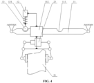
- FIG. 1 , FIG. 2 , FIG. 3 and FIG. 4 all show a state of the brake clamp 23 moving from a right end of the guide rail 11 to a left end of the guide rail 11 in the drawings.
- a sliding rail 121 extending in the vertical direction is provided on the base 12; a sliding block 122 that is moveable along an extension direction of the sliding rail 121 is provided on the sliding rail 121; and a top end of the spring 131 is connected to the sliding block 122.
- a force applied on the brake clamp 23 is transmitted to the sliding block 122 via the locking member 13, so as to drive the sliding block 122 to move appropriately along the sliding rail 121, which can effectively relieve the minor-scale swing and the structural impact of the brake clamp 23 during normal travelling, provide an effective buffering for an initial moving force of the brake clamp 23 when the vehicle performs the gauge-changing operation, prevent the force transmitted under a large-scale movement tendency of the brake clamp 23 from generating a rigid impact on the vehicle frame 22, and ensure the stability of the vehicle body and riding comfort of the rail vehicle.
- the locking member 13 is a connecting rod; two ends of the connecting rod are respectively hinged with the spring 131 and the brake clamp 23; the spring 131 is located directly above the midpoint of the guide rail 11, and a distance between the bottom end of the spring 131 in a limit compression state and the midpoint of the guide rail 11 is not less than a length of the connecting rod.
- This kind of connecting rod has a simple and reliable structure, and the distance between the bottom end of the spring 131 in the limit compression state and the midpoint of the guide rail 11 is not less than the length of the connecting rod, which can effectively prevent the brake clamp 23 from being blocked or stuck during the lateral movement, ensure the overall gauge-changing action efficiency and the assembly linkage of the brake clamp 23 and even the brake assembly, and improve the overall gauge-change action efficiency and travelling stability of the rail vehicle correspondingly.
- FIG. 3 is a schematic structural view of a brake assembly during movement provided according to another specific embodiment of the present invention
- FIG. 4 is a schematic structural view of the brake assembly in FIG. 3 after an action is completed.
- the locking member 13 is a locking pin connected to the bottom portion of the spring 131, and locking holes 111 that are detachably clamped with the locking pin are respectively provided on top portions of two ends of the guide rail 11.
- a force transmission efficiency of this kind of locking pin is relatively high.
- a component linkage process is flexible and efficient, and the locking holes 111 can lock the locking pin in time and accurately after the brake clamp 23 has been moved in position, so that a position of the brake clamp 23 is locked by linkage so as to prevent the brake clamp 23 from loosening or misalignment during the normal travelling of the vehicle, and ensure the travelling stability and comfort of the vehicle.
- the locking pin is a ball pin
- the locking hole 111 is a spherical hole.
- the stress distribution between the ball pin and related contacting members is relatively reasonable, which can effectively avoid the structural damage on related matching members caused by excessive rigid impact.
- the spherical hole can effectively reduce the resistance of the ball pin in the process of disengaging and engaging the hole, and can improve the alignment efficiency between the locking pin and the locking hole 111.
- a moving block 112 that is moveable along the extension direction of the guide rail 11 is provided on the guide rail 11; the brake clamp 23 is arranged at a bottom portion of the moving block 112 in linkage.
- the moving block 112 can provide a reliable structural connection between the brake clamp 23 and the guide rail 11, avoid interference with the main structure of the brake clamp 23 due to the direct connection of the brake clamp 23 and the guide rail 11, ensure the degree of freedom of braking and clamping action of the brake clamp 23 and the working stability of the brake clamp 23, and ensure the working reliability of the brake assembly of the rail vehicle.
- the rail vehicle provided according to the present invention includes a vehicle frame and a brake assembly, and the brake assembly is the brake assembly described in the above embodiments.
- the brake assembly of the rail vehicle has a wide-range lateral movement capability and can fully meet the requirement of working conditions when a rail vehicle is traveling on a gauge-changing rail.
- the brake disc drives the brake clamp to move accordingly along the extension direction of the guide rail, which achieves spacing adjustment of two corresponding brake clamps respectively arranged on two sides of the bottom of the vehicle body, so as to adapt to the adjusted rail gauge size, further ensure that relevant components of the rail vehicle can be adaptively adjusted according to the current gauge-changing operation, and ensure that the rail vehicle continues to maintain stable and continuous travelling after the gauge-changing operation is completed. Since the above brake clamp can move by a large displacement along the extension direction of the guide rail, an adjustment range of a lateral position of the brake clamp is greatly improved, and the adaptability of the gauge-changing working conditions of the rail vehicle can be improved accordingly.
- the rail vehicle using the above brake assembly provided according to the present invention has a wide-range lateral movement capability and can fully meet the requirement of working conditions when a rail vehicle is traveling on a gauge-changing rail.
Landscapes
- Engineering & Computer Science (AREA)
- Mechanical Engineering (AREA)
- General Engineering & Computer Science (AREA)
- Transportation (AREA)
- Braking Arrangements (AREA)
Claims (7)
- Bremsanordnung, die eine Bremsscheibe (21), die unter einem Fahrzeugrahmen (22) bereitgestellt ist, und eine Führungsschiene (11), die zwischen dem Fahrzeugrahmen (22) und der Bremsscheibe (21) bereitgestellt ist, aufweist, wobei die Führungsschiene (11) sich an einer Breitenrichtung des Fahrzeugrahmens (22) entlang erstreckt; wobei die Führungsschiene (11) mit einer auf die Bremsscheibe (21) aufgeklemmten Bremszange (23) versehen ist und die Bremszange (23) an einer Erstreckungsrichtung der Führungsschiene (11) entlang bewegbar ist, dadurch gekennzeichnet, dassein bewegter Block (112), der an der Erstreckungsrichtung der Führungsschiene (11) entlang bewegbar ist, an der Führungsschiene (11) bereitgestellt ist;und die Bremszange (23) an einem unteren Teil des bewegten Blocks (112) in Gestängeverbindung angeordnet ist.
- Bremsanordnung nach Anspruch 1, wobei am Fahrzeugrahmen (22) eine Basis (12) bereitgestellt ist und ein Arretierungselement (13), das mit der Bremszange (23) zusammenwirkt, unter der Basis (12) angeordnet ist; und eine Feder (131), die in vertikaler Richtung ausziehbar und zusammenziehbar ist, zwischen dem Arretierungselement (13) und der Basis (12) angeschlossen ist.
- Bremsanordnung nach Anspruch 2, wobei eine Gleitschiene (121), die sich in der vertikalen Richtung erstreckt, an der Basis (12) bereitgestellt ist; ein Gleitblock (122), der entlang einer Erstreckungsrichtung der Gleitschiene (121) beweglich ist, an der Gleitschiene (121) vorgesehen ist; und ein oberes Ende der Feder (131) mit dem Gleitblock (122) verbunden ist.
- Bremsanordnung nach Anspruch 2, wobei das Arretierungselement (13) eine Verbindungsstange ist; zwei Enden der Verbindungsstange an der Feder (131) bzw. der Bremszange (23) angelenkt sind; wobei die Feder (131) sich direkt über einem Mittelpunkt der Führungsschiene (11) befindet und ein Abstand zwischen einem unteren Ende der Feder (131) in einem Endkompressionszustand und dem Mittelpunkt der Führungsschiene (11) nicht kleiner als eine Länge der Verbindungsstange ist.
- Bremsanordnung nach Anspruch 2, wobei das Arretierungselement (13) ein Arretierungsstift ist, der mit einem unteren Teil der Feder (131) verbunden ist, und Arretierungslöcher (111), die abnehmbar auf den Arretierungsstift geklemmt werden, jeweils an oberen Teilen von zwei Enden der Führungsschiene (11) bereitgestellt sind.
- Bremsanordnung nach Anspruch 5, wobei der Arretierungsbolzen ein Kugelbolzen ist, und jedes der Arretierungslöcher (111) ein kugelförmiges Loch ist.
- Schienenfahrzeug, das einen Fahrzeugrahmen (22) und eine Bremsanordnung aufweist, wobei die Bremsanordnung die Bremsanordnung nach einem der Ansprüche 1 bis 6 ist.
Priority Applications (1)
| Application Number | Priority Date | Filing Date | Title |
|---|---|---|---|
| RS20240173A RS65151B1 (sr) | 2019-07-31 | 2020-06-11 | Šinsko vozilo i njegov kočioni sklop |
Applications Claiming Priority (2)
| Application Number | Priority Date | Filing Date | Title |
|---|---|---|---|
| CN201910703018.0A CN110371157B (zh) | 2019-07-31 | 2019-07-31 | 轨道车辆及其制动组件 |
| PCT/CN2020/095567 WO2021017657A1 (zh) | 2019-07-31 | 2020-06-11 | 轨道车辆及其制动组件 |
Publications (3)
| Publication Number | Publication Date |
|---|---|
| EP3957540A1 EP3957540A1 (de) | 2022-02-23 |
| EP3957540A4 EP3957540A4 (de) | 2022-08-24 |
| EP3957540B1 true EP3957540B1 (de) | 2023-12-13 |
Family
ID=68257514
Family Applications (1)
| Application Number | Title | Priority Date | Filing Date |
|---|---|---|---|
| EP20847806.5A Active EP3957540B1 (de) | 2019-07-31 | 2020-06-11 | Schienenfahrzeug und bremsanordnung dafür |
Country Status (7)
| Country | Link |
|---|---|
| EP (1) | EP3957540B1 (de) |
| CN (1) | CN110371157B (de) |
| HU (1) | HUE064858T2 (de) |
| MY (1) | MY209433A (de) |
| RS (1) | RS65151B1 (de) |
| SG (1) | SG11202112343XA (de) |
| WO (1) | WO2021017657A1 (de) |
Families Citing this family (1)
| Publication number | Priority date | Publication date | Assignee | Title |
|---|---|---|---|---|
| CN110371157B (zh) * | 2019-07-31 | 2020-12-25 | 中车长春轨道客车股份有限公司 | 轨道车辆及其制动组件 |
Family Cites Families (10)
| Publication number | Priority date | Publication date | Assignee | Title |
|---|---|---|---|---|
| US3118258A (en) * | 1961-03-03 | 1964-01-21 | Machine machine | |
| JP4182553B2 (ja) * | 1997-11-10 | 2008-11-19 | 株式会社竹屋 | パチンコ遊技機の発射操作部の変位制御装置 |
| JP2003205840A (ja) * | 2002-01-16 | 2003-07-22 | Fuji Heavy Ind Ltd | 鉄道車両用軌間可変台車の排障器 |
| CN106915361B (zh) * | 2017-03-21 | 2019-04-12 | 中车山东机车车辆有限公司 | 一种装用可调节单元制动装置的变轨距转向架 |
| CN107628059B (zh) * | 2017-09-01 | 2023-05-26 | 中车唐山机车车辆有限公司 | 一种应用于变轨距转向架的制动装置 |
| CN108482415B (zh) * | 2018-03-12 | 2020-02-14 | 中车青岛四方车辆研究所有限公司 | 变轨距转向架用刚性随动机构及制动夹钳单元 |
| CN108423027B (zh) * | 2018-03-16 | 2019-07-12 | 中车青岛四方车辆研究所有限公司 | 用于变轨距转向架的随动机构及制动夹钳单元 |
| CN108609028B (zh) * | 2018-04-13 | 2020-05-12 | 中车青岛四方机车车辆股份有限公司 | 一种轨道车辆用动车变轨距转向架 |
| CN109501831B (zh) * | 2018-12-07 | 2024-04-26 | 中国铁道科学研究院集团有限公司 | 制动夹钳变轨装置 |
| CN110371157B (zh) * | 2019-07-31 | 2020-12-25 | 中车长春轨道客车股份有限公司 | 轨道车辆及其制动组件 |
-
2019
- 2019-07-31 CN CN201910703018.0A patent/CN110371157B/zh active Active
-
2020
- 2020-06-11 RS RS20240173A patent/RS65151B1/sr unknown
- 2020-06-11 HU HUE20847806A patent/HUE064858T2/hu unknown
- 2020-06-11 WO PCT/CN2020/095567 patent/WO2021017657A1/zh not_active Ceased
- 2020-06-11 EP EP20847806.5A patent/EP3957540B1/de active Active
- 2020-06-11 MY MYPI2021006699A patent/MY209433A/en unknown
- 2020-06-11 SG SG11202112343XA patent/SG11202112343XA/en unknown
Also Published As
| Publication number | Publication date |
|---|---|
| CN110371157A (zh) | 2019-10-25 |
| WO2021017657A1 (zh) | 2021-02-04 |
| HUE064858T2 (hu) | 2024-04-28 |
| CN110371157B (zh) | 2020-12-25 |
| EP3957540A4 (de) | 2022-08-24 |
| SG11202112343XA (en) | 2021-12-30 |
| EP3957540A1 (de) | 2022-02-23 |
| MY209433A (en) | 2025-07-09 |
| RS65151B1 (sr) | 2024-02-29 |
Similar Documents
| Publication | Publication Date | Title |
|---|---|---|
| CN102216142B (zh) | 具有牵引/俯仰控制组件的单轨转向架 | |
| RU2729854C1 (ru) | Следящий механизм и блок суппорта тормоза для тележки с изменяемой шириной колеи | |
| JP5133237B2 (ja) | 台車横移動規制システム | |
| CN108146403B (zh) | 一种跨座式单轨转向架组件检修及更换设备 | |
| US10308262B2 (en) | Bearing bracket, assembly containing such a bearing bracket and system containing such an assembly | |
| MX2015005013A (es) | Dispositivo centrador de resorte de torsion de acoplador. | |
| KR102218950B1 (ko) | 궤간가변 대차에 적용되는 답면 제동장치 | |
| CN109591534A (zh) | 用于车辆的轴距调节装置 | |
| CN109177666B (zh) | 一种agv小车的牵引机构 | |
| CN105571877A (zh) | 一种试验车辆牵引机构及碰撞系统 | |
| CN102416966A (zh) | 一种磁浮车辆中间滑台连接装置 | |
| CN110435706B (zh) | 一种悬挂式prt车辆的车钩装置 | |
| CN210122116U (zh) | 转向架和单轨作业车 | |
| EP3957540A1 (de) | Schienenfahrzeug und bremsanordnung dafür | |
| RU2578642C1 (ru) | Блок удержания состава на станционном пути | |
| US5524552A (en) | Single axle truck for large railroad cars | |
| CN109733816B (zh) | 一种台车 | |
| TW577948B (en) | A dual-functional railroad vehicle for carrying out works on track superstructure | |
| CN218140906U (zh) | 车辆用便于快速结合的连接机构 | |
| CN203637623U (zh) | 吸能装置及使用该吸能装置的后移式座椅 | |
| CN218021641U (zh) | 一种用于车轮的止退装置及过跨车 | |
| RU2207278C2 (ru) | Упругий упор для закрепления железнодорожного подвижного состава | |
| RU2658746C1 (ru) | Блок удержания состава на станционном пути | |
| CN113931015A (zh) | 一种轨道交通用间隙桥接装置 | |
| CN217532850U (zh) | 一种机车车厢连接器安装机构 |
Legal Events
| Date | Code | Title | Description |
|---|---|---|---|
| STAA | Information on the status of an ep patent application or granted ep patent |
Free format text: STATUS: THE INTERNATIONAL PUBLICATION HAS BEEN MADE |
|
| PUAI | Public reference made under article 153(3) epc to a published international application that has entered the european phase |
Free format text: ORIGINAL CODE: 0009012 |
|
| STAA | Information on the status of an ep patent application or granted ep patent |
Free format text: STATUS: REQUEST FOR EXAMINATION WAS MADE |
|
| 17P | Request for examination filed |
Effective date: 20211119 |
|
| AK | Designated contracting states |
Kind code of ref document: A1 Designated state(s): AL AT BE BG CH CY CZ DE DK EE ES FI FR GB GR HR HU IE IS IT LI LT LU LV MC MK MT NL NO PL PT RO RS SE SI SK SM TR |
|
| A4 | Supplementary search report drawn up and despatched |
Effective date: 20220727 |
|
| RIC1 | Information provided on ipc code assigned before grant |
Ipc: B61H 5/00 20060101AFI20220722BHEP |
|
| DAV | Request for validation of the european patent (deleted) | ||
| DAX | Request for extension of the european patent (deleted) | ||
| GRAP | Despatch of communication of intention to grant a patent |
Free format text: ORIGINAL CODE: EPIDOSNIGR1 |
|
| STAA | Information on the status of an ep patent application or granted ep patent |
Free format text: STATUS: GRANT OF PATENT IS INTENDED |
|
| INTG | Intention to grant announced |
Effective date: 20230705 |
|
| GRAS | Grant fee paid |
Free format text: ORIGINAL CODE: EPIDOSNIGR3 |
|
| GRAA | (expected) grant |
Free format text: ORIGINAL CODE: 0009210 |
|
| STAA | Information on the status of an ep patent application or granted ep patent |
Free format text: STATUS: THE PATENT HAS BEEN GRANTED |
|
| AK | Designated contracting states |
Kind code of ref document: B1 Designated state(s): AL AT BE BG CH CY CZ DE DK EE ES FI FR GB GR HR HU IE IS IT LI LT LU LV MC MK MT NL NO PL PT RO RS SE SI SK SM TR |
|
| REG | Reference to a national code |
Ref country code: GB Ref legal event code: FG4D |
|
| REG | Reference to a national code |
Ref country code: CH Ref legal event code: EP |
|
| REG | Reference to a national code |
Ref country code: DE Ref legal event code: R096 Ref document number: 602020022859 Country of ref document: DE |
|
| REG | Reference to a national code |
Ref country code: IE Ref legal event code: FG4D |
|
| PG25 | Lapsed in a contracting state [announced via postgrant information from national office to epo] |
Ref country code: GR Free format text: LAPSE BECAUSE OF FAILURE TO SUBMIT A TRANSLATION OF THE DESCRIPTION OR TO PAY THE FEE WITHIN THE PRESCRIBED TIME-LIMIT Effective date: 20240314 |
|
| REG | Reference to a national code |
Ref country code: LT Ref legal event code: MG9D |
|
| PG25 | Lapsed in a contracting state [announced via postgrant information from national office to epo] |
Ref country code: LT Free format text: LAPSE BECAUSE OF FAILURE TO SUBMIT A TRANSLATION OF THE DESCRIPTION OR TO PAY THE FEE WITHIN THE PRESCRIBED TIME-LIMIT Effective date: 20231213 |
|
| REG | Reference to a national code |
Ref country code: NL Ref legal event code: MP Effective date: 20231213 |
|
| PG25 | Lapsed in a contracting state [announced via postgrant information from national office to epo] |
Ref country code: ES Free format text: LAPSE BECAUSE OF FAILURE TO SUBMIT A TRANSLATION OF THE DESCRIPTION OR TO PAY THE FEE WITHIN THE PRESCRIBED TIME-LIMIT Effective date: 20231213 |
|
| REG | Reference to a national code |
Ref country code: HU Ref legal event code: AG4A Ref document number: E064858 Country of ref document: HU |
|
| PG25 | Lapsed in a contracting state [announced via postgrant information from national office to epo] |
Ref country code: LT Free format text: LAPSE BECAUSE OF FAILURE TO SUBMIT A TRANSLATION OF THE DESCRIPTION OR TO PAY THE FEE WITHIN THE PRESCRIBED TIME-LIMIT Effective date: 20231213 Ref country code: GR Free format text: LAPSE BECAUSE OF FAILURE TO SUBMIT A TRANSLATION OF THE DESCRIPTION OR TO PAY THE FEE WITHIN THE PRESCRIBED TIME-LIMIT Effective date: 20240314 Ref country code: ES Free format text: LAPSE BECAUSE OF FAILURE TO SUBMIT A TRANSLATION OF THE DESCRIPTION OR TO PAY THE FEE WITHIN THE PRESCRIBED TIME-LIMIT Effective date: 20231213 Ref country code: BG Free format text: LAPSE BECAUSE OF FAILURE TO SUBMIT A TRANSLATION OF THE DESCRIPTION OR TO PAY THE FEE WITHIN THE PRESCRIBED TIME-LIMIT Effective date: 20240313 |
|
| REG | Reference to a national code |
Ref country code: AT Ref legal event code: MK05 Ref document number: 1640235 Country of ref document: AT Kind code of ref document: T Effective date: 20231213 |
|
| PG25 | Lapsed in a contracting state [announced via postgrant information from national office to epo] |
Ref country code: NL Free format text: LAPSE BECAUSE OF FAILURE TO SUBMIT A TRANSLATION OF THE DESCRIPTION OR TO PAY THE FEE WITHIN THE PRESCRIBED TIME-LIMIT Effective date: 20231213 |
|
| PG25 | Lapsed in a contracting state [announced via postgrant information from national office to epo] |
Ref country code: SE Free format text: LAPSE BECAUSE OF FAILURE TO SUBMIT A TRANSLATION OF THE DESCRIPTION OR TO PAY THE FEE WITHIN THE PRESCRIBED TIME-LIMIT Effective date: 20231213 Ref country code: NO Free format text: LAPSE BECAUSE OF FAILURE TO SUBMIT A TRANSLATION OF THE DESCRIPTION OR TO PAY THE FEE WITHIN THE PRESCRIBED TIME-LIMIT Effective date: 20240313 Ref country code: NL Free format text: LAPSE BECAUSE OF FAILURE TO SUBMIT A TRANSLATION OF THE DESCRIPTION OR TO PAY THE FEE WITHIN THE PRESCRIBED TIME-LIMIT Effective date: 20231213 Ref country code: LV Free format text: LAPSE BECAUSE OF FAILURE TO SUBMIT A TRANSLATION OF THE DESCRIPTION OR TO PAY THE FEE WITHIN THE PRESCRIBED TIME-LIMIT Effective date: 20231213 Ref country code: HR Free format text: LAPSE BECAUSE OF FAILURE TO SUBMIT A TRANSLATION OF THE DESCRIPTION OR TO PAY THE FEE WITHIN THE PRESCRIBED TIME-LIMIT Effective date: 20231213 |
|
| PG25 | Lapsed in a contracting state [announced via postgrant information from national office to epo] |
Ref country code: IS Free format text: LAPSE BECAUSE OF FAILURE TO SUBMIT A TRANSLATION OF THE DESCRIPTION OR TO PAY THE FEE WITHIN THE PRESCRIBED TIME-LIMIT Effective date: 20240413 |
|
| PG25 | Lapsed in a contracting state [announced via postgrant information from national office to epo] |
Ref country code: CZ Free format text: LAPSE BECAUSE OF FAILURE TO SUBMIT A TRANSLATION OF THE DESCRIPTION OR TO PAY THE FEE WITHIN THE PRESCRIBED TIME-LIMIT Effective date: 20231213 Ref country code: AT Free format text: LAPSE BECAUSE OF FAILURE TO SUBMIT A TRANSLATION OF THE DESCRIPTION OR TO PAY THE FEE WITHIN THE PRESCRIBED TIME-LIMIT Effective date: 20231213 |
|
| PG25 | Lapsed in a contracting state [announced via postgrant information from national office to epo] |
Ref country code: SK Free format text: LAPSE BECAUSE OF FAILURE TO SUBMIT A TRANSLATION OF THE DESCRIPTION OR TO PAY THE FEE WITHIN THE PRESCRIBED TIME-LIMIT Effective date: 20231213 |
|
| PG25 | Lapsed in a contracting state [announced via postgrant information from national office to epo] |
Ref country code: SM Free format text: LAPSE BECAUSE OF FAILURE TO SUBMIT A TRANSLATION OF THE DESCRIPTION OR TO PAY THE FEE WITHIN THE PRESCRIBED TIME-LIMIT Effective date: 20231213 Ref country code: SK Free format text: LAPSE BECAUSE OF FAILURE TO SUBMIT A TRANSLATION OF THE DESCRIPTION OR TO PAY THE FEE WITHIN THE PRESCRIBED TIME-LIMIT Effective date: 20231213 Ref country code: RO Free format text: LAPSE BECAUSE OF FAILURE TO SUBMIT A TRANSLATION OF THE DESCRIPTION OR TO PAY THE FEE WITHIN THE PRESCRIBED TIME-LIMIT Effective date: 20231213 Ref country code: IT Free format text: LAPSE BECAUSE OF FAILURE TO SUBMIT A TRANSLATION OF THE DESCRIPTION OR TO PAY THE FEE WITHIN THE PRESCRIBED TIME-LIMIT Effective date: 20231213 Ref country code: IS Free format text: LAPSE BECAUSE OF FAILURE TO SUBMIT A TRANSLATION OF THE DESCRIPTION OR TO PAY THE FEE WITHIN THE PRESCRIBED TIME-LIMIT Effective date: 20240413 Ref country code: EE Free format text: LAPSE BECAUSE OF FAILURE TO SUBMIT A TRANSLATION OF THE DESCRIPTION OR TO PAY THE FEE WITHIN THE PRESCRIBED TIME-LIMIT Effective date: 20231213 Ref country code: CZ Free format text: LAPSE BECAUSE OF FAILURE TO SUBMIT A TRANSLATION OF THE DESCRIPTION OR TO PAY THE FEE WITHIN THE PRESCRIBED TIME-LIMIT Effective date: 20231213 Ref country code: AT Free format text: LAPSE BECAUSE OF FAILURE TO SUBMIT A TRANSLATION OF THE DESCRIPTION OR TO PAY THE FEE WITHIN THE PRESCRIBED TIME-LIMIT Effective date: 20231213 |
|
| PG25 | Lapsed in a contracting state [announced via postgrant information from national office to epo] |
Ref country code: PL Free format text: LAPSE BECAUSE OF FAILURE TO SUBMIT A TRANSLATION OF THE DESCRIPTION OR TO PAY THE FEE WITHIN THE PRESCRIBED TIME-LIMIT Effective date: 20231213 Ref country code: PT Free format text: LAPSE BECAUSE OF FAILURE TO SUBMIT A TRANSLATION OF THE DESCRIPTION OR TO PAY THE FEE WITHIN THE PRESCRIBED TIME-LIMIT Effective date: 20240415 |
|
| PG25 | Lapsed in a contracting state [announced via postgrant information from national office to epo] |
Ref country code: PT Free format text: LAPSE BECAUSE OF FAILURE TO SUBMIT A TRANSLATION OF THE DESCRIPTION OR TO PAY THE FEE WITHIN THE PRESCRIBED TIME-LIMIT Effective date: 20240415 Ref country code: PL Free format text: LAPSE BECAUSE OF FAILURE TO SUBMIT A TRANSLATION OF THE DESCRIPTION OR TO PAY THE FEE WITHIN THE PRESCRIBED TIME-LIMIT Effective date: 20231213 |
|
| REG | Reference to a national code |
Ref country code: DE Ref legal event code: R097 Ref document number: 602020022859 Country of ref document: DE |
|
| PG25 | Lapsed in a contracting state [announced via postgrant information from national office to epo] |
Ref country code: DK Free format text: LAPSE BECAUSE OF FAILURE TO SUBMIT A TRANSLATION OF THE DESCRIPTION OR TO PAY THE FEE WITHIN THE PRESCRIBED TIME-LIMIT Effective date: 20231213 |
|
| PLBE | No opposition filed within time limit |
Free format text: ORIGINAL CODE: 0009261 |
|
| STAA | Information on the status of an ep patent application or granted ep patent |
Free format text: STATUS: NO OPPOSITION FILED WITHIN TIME LIMIT |
|
| PG25 | Lapsed in a contracting state [announced via postgrant information from national office to epo] |
Ref country code: SI Free format text: LAPSE BECAUSE OF FAILURE TO SUBMIT A TRANSLATION OF THE DESCRIPTION OR TO PAY THE FEE WITHIN THE PRESCRIBED TIME-LIMIT Effective date: 20231213 |
|
| PG25 | Lapsed in a contracting state [announced via postgrant information from national office to epo] |
Ref country code: SI Free format text: LAPSE BECAUSE OF FAILURE TO SUBMIT A TRANSLATION OF THE DESCRIPTION OR TO PAY THE FEE WITHIN THE PRESCRIBED TIME-LIMIT Effective date: 20231213 Ref country code: DK Free format text: LAPSE BECAUSE OF FAILURE TO SUBMIT A TRANSLATION OF THE DESCRIPTION OR TO PAY THE FEE WITHIN THE PRESCRIBED TIME-LIMIT Effective date: 20231213 |
|
| 26N | No opposition filed |
Effective date: 20240916 |
|
| PG25 | Lapsed in a contracting state [announced via postgrant information from national office to epo] |
Ref country code: MC Free format text: LAPSE BECAUSE OF FAILURE TO SUBMIT A TRANSLATION OF THE DESCRIPTION OR TO PAY THE FEE WITHIN THE PRESCRIBED TIME-LIMIT Effective date: 20231213 |
|
| REG | Reference to a national code |
Ref country code: CH Ref legal event code: PL |
|
| PG25 | Lapsed in a contracting state [announced via postgrant information from national office to epo] |
Ref country code: LU Free format text: LAPSE BECAUSE OF NON-PAYMENT OF DUE FEES Effective date: 20240611 |
|
| GBPC | Gb: european patent ceased through non-payment of renewal fee |
Effective date: 20240611 |
|
| PG25 | Lapsed in a contracting state [announced via postgrant information from national office to epo] |
Ref country code: IE Free format text: LAPSE BECAUSE OF NON-PAYMENT OF DUE FEES Effective date: 20240611 |
|
| PG25 | Lapsed in a contracting state [announced via postgrant information from national office to epo] |
Ref country code: BE Free format text: LAPSE BECAUSE OF NON-PAYMENT OF DUE FEES Effective date: 20240630 Ref country code: CH Free format text: LAPSE BECAUSE OF NON-PAYMENT OF DUE FEES Effective date: 20240630 |
|
| PG25 | Lapsed in a contracting state [announced via postgrant information from national office to epo] |
Ref country code: FR Free format text: LAPSE BECAUSE OF NON-PAYMENT OF DUE FEES Effective date: 20240630 |
|
| PG25 | Lapsed in a contracting state [announced via postgrant information from national office to epo] |
Ref country code: GB Free format text: LAPSE BECAUSE OF NON-PAYMENT OF DUE FEES Effective date: 20240611 |
|
| REG | Reference to a national code |
Ref country code: BE Ref legal event code: MM Effective date: 20240630 |
|
| PGFP | Annual fee paid to national office [announced via postgrant information from national office to epo] |
Ref country code: RS Payment date: 20250604 Year of fee payment: 6 |
|
| PGFP | Annual fee paid to national office [announced via postgrant information from national office to epo] |
Ref country code: HU Payment date: 20250606 Year of fee payment: 6 |
|
| PG25 | Lapsed in a contracting state [announced via postgrant information from national office to epo] |
Ref country code: FI Free format text: LAPSE BECAUSE OF FAILURE TO SUBMIT A TRANSLATION OF THE DESCRIPTION OR TO PAY THE FEE WITHIN THE PRESCRIBED TIME-LIMIT Effective date: 20231213 |
|
| PGFP | Annual fee paid to national office [announced via postgrant information from national office to epo] |
Ref country code: DE Payment date: 20250711 Year of fee payment: 6 |
|
| PG25 | Lapsed in a contracting state [announced via postgrant information from national office to epo] |
Ref country code: CY Free format text: LAPSE BECAUSE OF FAILURE TO SUBMIT A TRANSLATION OF THE DESCRIPTION OR TO PAY THE FEE WITHIN THE PRESCRIBED TIME-LIMIT; INVALID AB INITIO Effective date: 20200611 |