EP3957779B1 - Riemen einer brech- und schwingmaschine mit armatur für den vorschub von pflanzenstängeln - Google Patents
Riemen einer brech- und schwingmaschine mit armatur für den vorschub von pflanzenstängeln Download PDFInfo
- Publication number
- EP3957779B1 EP3957779B1 EP21190672.2A EP21190672A EP3957779B1 EP 3957779 B1 EP3957779 B1 EP 3957779B1 EP 21190672 A EP21190672 A EP 21190672A EP 3957779 B1 EP3957779 B1 EP 3957779B1
- Authority
- EP
- European Patent Office
- Prior art keywords
- belt
- reinforcement
- longitudinal direction
- belt according
- face
- Prior art date
- Legal status (The legal status is an assumption and is not a legal conclusion. Google has not performed a legal analysis and makes no representation as to the accuracy of the status listed.)
- Active
Links
Images



Classifications
-
- D—TEXTILES; PAPER
- D01—NATURAL OR MAN-MADE THREADS OR FIBRES; SPINNING
- D01B—MECHANICAL TREATMENT OF NATURAL FIBROUS OR FILAMENTARY MATERIAL TO OBTAIN FIBRES OF FILAMENTS, e.g. FOR SPINNING
- D01B1/00—Mechanical separation of fibres from plant material, e.g. seeds, leaves, stalks
- D01B1/10—Separating vegetable fibres from stalks or leaves
- D01B1/14—Breaking or scutching, e.g. of flax; Decorticating
- D01B1/30—Details of machines
- D01B1/34—Devices holding fibres or fibre-bearing materials during treatment
- D01B1/36—Conveying devices, e.g. moving bands or ropes
-
- F—MECHANICAL ENGINEERING; LIGHTING; HEATING; WEAPONS; BLASTING
- F16—ENGINEERING ELEMENTS AND UNITS; GENERAL MEASURES FOR PRODUCING AND MAINTAINING EFFECTIVE FUNCTIONING OF MACHINES OR INSTALLATIONS; THERMAL INSULATION IN GENERAL
- F16G—BELTS, CABLES, OR ROPES, PREDOMINANTLY USED FOR DRIVING PURPOSES; CHAINS; FITTINGS PREDOMINANTLY USED THEREFOR
- F16G3/00—Belt fastenings, e.g. for conveyor belts
- F16G3/10—Joining belts by sewing, sticking, vulcanising, or the like; Constructional adaptations of the belt ends for this purpose
-
- F—MECHANICAL ENGINEERING; LIGHTING; HEATING; WEAPONS; BLASTING
- F16—ENGINEERING ELEMENTS AND UNITS; GENERAL MEASURES FOR PRODUCING AND MAINTAINING EFFECTIVE FUNCTIONING OF MACHINES OR INSTALLATIONS; THERMAL INSULATION IN GENERAL
- F16G—BELTS, CABLES, OR ROPES, PREDOMINANTLY USED FOR DRIVING PURPOSES; CHAINS; FITTINGS PREDOMINANTLY USED THEREFOR
- F16G5/00—V-belts, i.e. belts of tapered cross-section
- F16G5/04—V-belts, i.e. belts of tapered cross-section made of rubber
- F16G5/06—V-belts, i.e. belts of tapered cross-section made of rubber with reinforcement bonded by the rubber
- F16G5/10—V-belts, i.e. belts of tapered cross-section made of rubber with reinforcement bonded by the rubber with metal reinforcement
-
- F—MECHANICAL ENGINEERING; LIGHTING; HEATING; WEAPONS; BLASTING
- F16—ENGINEERING ELEMENTS AND UNITS; GENERAL MEASURES FOR PRODUCING AND MAINTAINING EFFECTIVE FUNCTIONING OF MACHINES OR INSTALLATIONS; THERMAL INSULATION IN GENERAL
- F16G—BELTS, CABLES, OR ROPES, PREDOMINANTLY USED FOR DRIVING PURPOSES; CHAINS; FITTINGS PREDOMINANTLY USED THEREFOR
- F16G7/00—V-belt fastenings
Definitions
- the invention relates to the field of scutching plant stems, such as flax or hemp.
- Scutching essentially consists of crushing the stems and then beating them in order to separate the fibers from the wood. At the end of the scutching process, a sheet of tow is obtained.
- a machine called a scutcher is commonly used.
- a scutcher generally includes a drive device for transporting the plant stems in the longitudinal direction of the scutcher through the different modules of the scutching machine, in particular the grinding module and then the threshing modules which are equipped with turbines intended to beat the stems in order to remove the shives.
- the drive device traditionally comprises a chain of metal links that have the shape of a "U". These links are fixed to a flat strap closed on itself and which is mounted on drive rollers. The links are fixed on the outer face of the strap, that is to say the face that does not come into contact with the drive rollers.
- the drive device further comprises a drive belt that is arranged to be housed between the wings of the links.
- this belt when not mounted, has an oval shape and a longitudinal direction; it has a thickness defined between an inner face and an outer face of the belt, the belt having a rubber body extending in the longitudinal direction. Its cross section generally has a substantially rectangular or trapezoidal shape.
- the belt also has a width defined between first and second sides of the belt.
- the outer and inner faces are defined with reference to the oval formed by the belt.
- the belt is arranged to removably engage in the links of so that the first and second sides of the belt come to bear against the wings of the links.
- the belt traditionally has one strand that is longer than the strap strand, so that the belt is only engaged in links of the drive device and pinches the plant stems over part of the length of the belt strand.
- the chain and belt each form an oval with a return strand upwards for the chain and downwards for the belt.
- the plant stems are fed in the form of a sheet upstream of the drive device, i.e. just before the belt engages in the links.
- the plant stems, oriented perpendicular to the direction of movement of the belt, are then gripped between the belt and the links of the drive device, then moved in the longitudinal direction of the belt - thanks to the engagement of the belt in the chain - in order to be transported into the various modules of the scutcher.
- plant layer separates from the drive device, downstream, at the moment when the belt disengages from the links.
- the successive engagement and disengagement of the belt in the links has the effect of wearing out the constituent parts of the drive device, and in particular the plant stem drive belt.
- the belt breaks due to the mechanical stress it undergoes, which requires stopping the slitting machine in order to repair the broken belt.
- the repair consists of beveling the two ends of the belt before gluing them together. It is understood that a repaired belt is less robust than a new belt. When the belt cannot be repaired, it must be changed.
- a cutter is for example known from the document US 1589 732 A , which shows the preamble of claim 1.
- An aim of the present invention is to provide a belt that is more robust than traditional belts, particularly at the junction between the two ends of the belt.
- the body comprises first and second end portions fixed to each other so that the body forms a first loop
- the reinforcement comprises first and second end portions fixed to each other so that the reinforcement forms a second loop included in the first loop
- the belt further comprises at least one first longitudinal cavity, parallel to the reinforcement and arranged between the reinforcement and the first sidewall of the belt, the first longitudinal cavity extending in the longitudinal direction of the body of the belt and forming a cell which extends in the longitudinal direction of the body, so as to increase the elastic deformability of the belt along its width
- the reinforcement further comprises a holding device for preventing the reinforcement from sliding relative to the rubber body in the longitudinal direction.
- the frame is metallic. It could also be made of another material having a high tensile strength, for example a composite or carbon material, or any other tensile-resistant material.
- the purpose of the reinforcement is to give the belt a tensile strength significantly greater than that of the rubber body. This increases the robustness of the belt.
- the reinforcement consists of a flat strip having a first face and a second face parallel to the first face, the first face being parallel to the outer face of the belt.
- the flat strip is preferably metallic.
- the reinforcement therefore has the shape of a ribbon.
- the belt retains flexibility in bending ensuring deformation when passing the drive rollers.
- the first and second end portions of the frame overlap at a fixing zone.
- the first and second end portions may also be secured to each other using a connecting piece provided and connecting the first and second end portions.
- the first and second end parts of the frame are fixed end to end by form cooperation.
- first and second end portions of the frame are secured to each other by crimping, welding, riveting or stapling.
- the holding device comprises fins which extend transversely to the longitudinal direction, the fins being embedded in the rubber body.
- the fins extend transversely to a central part of the frame.
- the fins increase the grip surface between the frame and the rubber body, which has the effect of preventing the frame from slipping relative to the body.
- two adjacent fins are spaced apart from each other in the longitudinal direction.
- the fins are preferably arranged along the length of the frame, and preferably protrude on either side of the central part of the frame.
- the holding device comprises a coating, for example a film, arranged at least partly around the frame in order to increase the coefficient of friction between the frame and the rubber body.
- the first end portion of the frame is positioned between the second end portion of the frame and the second end portion of the body.
- the second end portion of the frame is positioned between the first end portion of the frame and the first end portion of the body.
- This sandwich-type assembly provides a robust attachment between the end portions of the body and the end portions of the frame, while ensuring the loop-shaped continuity of the body and the frame.
- the first and second end portions of the body are arranged on either side of the frame.
- the first and second end portions of the body are fixed to each other by gluing or vulcanization.
- the first longitudinal cavity preferably has an oblong cross-section extending between the inner face and the outer face of the belt.
- the first longitudinal cavity makes it possible to increase the elastic deformability of the belt according to its width and, consequently, makes it easier to engage and disengage the belt in links of the scutcher chain.
- the first cavity is entirely housed in the body.
- the first cavity is empty; however, it could be filled with a deformable foam-type material without departing from the scope of the present invention.
- the body further comprises a second longitudinal cavity, parallel to the first longitudinal cavity and arranged between the reinforcement and a second side of the belt, the reinforcement being arranged between the first and second longitudinal cavities.
- This second longitudinal cavity extends in the longitudinal direction of the belt body. It forms a second cell which extends in the longitudinal direction of the body.
- the second longitudinal cavity makes it possible to further increase the elastic deformability of the belt according to its width and, consequently, makes it easier to engage and disengage the belt in links of the scutcher chain.
- the link chain comprises links which include wings between which the first and second sides of the belt are engaged.
- a scutcher 10 according to the present invention has been very schematically illustrated, and more particularly a drive system 12 for moving plant stems T, for example flax stems, in a direction of advance S which is parallel to the longitudinal direction of the scutcher 10.
- the plant stem drive system 12 comprises, in this schematic example, a plant stem drive device 18 T.
- the cutter 10 also includes a movement system 22 for setting the drive device 18 in motion.
- the movement system 22 comprises a motor member 22a for rotating a drive pulley 23 cooperating respectively with the drive device 18.
- a driven pulley 24 is also provided which cooperates with the chain.
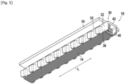
- the plant stem drive device 18 for the scutcher 10 comprises a chain 30, illustrated in figure 5 , which consists of a succession of links 32, the chain 30 is fixed to a drive strap 34, for example using rivets.
- the links are preferably made of a rigid material, for example metal.
- Each link 32 has the shape of a “U” which has two wings 38, 40 parallel to each other, each of the wings extending perpendicularly from a base 42 of the link.
- the bases of the links are fixed to the drive strap 34.
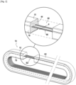
- the drive device 18 further comprises a belt 14, which is shaped to cooperate with the links 32 of the chain of the drive device 18. This belt forms a loop.
- the belt 14 cooperates with rollers 13.
- the active strand 14a of the belt 14 engages with the chain 30, while the return strand 14b passes, in a known manner, below the rail 16.
- each of the links 32 has a housing, which is defined between the base and the two parallel wings. This housing is intended to receive the belt 14.
- the belt 14 is removably housed in the housings of the links 32. Upstream of the drive device, the plant stems engage between the links and the belt 14. The plant stems T then being pinched between the belt 14 and the links, it is understood that the setting in motion of the drive device has the effect of moving the belt together with the plant stems T in the direction of movement S.
- the belt 14 is arranged to be inserted into the housings, that is to say between the wings 38, 40 of the links 32 of the chain 30.
- the belt further has a width l which is defined between first and second flanks 19, 21 of the belt 14.
- the belt 14 has a longitudinal direction L, a thickness E defined between an outer face 15 and an inner face 17 of said belt.
- the first and second sides 19, 21 of the belt 14 are intended to come into contact with the wings 38, 40 of the links 32 when the belt 14 is engaged in the chain 30.
- the belt 14 has a rubber body 44 .
- the body 44 of the belt 14 comprises a central portion 50, as well as a first lateral portion 52 and a second lateral portion 54 opposite the first lateral portion 52.
- the first and second lateral portions are arranged respectively between the central portion and the first and first and second flanks.
- the body 44 comprises first and second end portions 46, 48, which are fixed to each other such that the body 44 forms a first loop B1.
- the first and second end portions 46, 48 of the body 44 are fixed to each other by gluing or vulcanization.
- the belt 14 further comprises a reinforcement 60, preferably metallic, which is arranged inside the body 44. As illustrated in the figures, the body extends in the longitudinal direction. Furthermore, the reinforcement 60 comprises first and second end portions 62, 64 which are fixed to each other so that the reinforcement forms a second loop B2 included in the first loop B1.
- the armature 60 is made up of a flat strip 66 having a first face 66A and a second face 66b opposite the first face 66a , the first face 66a being parallel to the outer face 15 of the belt 14.
- the frame 60 is arranged in the portion 50 of the body 44.
- the width a of the reinforcement 60 is, in this example, approximately equal to half the width l of the belt 14.
- first and second end portions 62, 64 of the frame overlap along a fastening zone Z. More specifically, in this non-limiting example, the first and second end portions 62, 64 are fastened to each other by riveting. They could also be fastened to each other by crimping, welding, or stapling, or by any other fastening means.
- the fixing zone Z extends over a fraction of the length of the frame 60, which is of the order of a few centimeters in this example.
- the first end portion 62 of the frame 60 is positioned between the second end portion 64 of the frame 60 and the second end portion 48 of the body 44.
- the second end portion 64 of the frame 60 is positioned between the first end portion 62 of the frame 60 and the first end portion 46 of the body.
- first and second end portions 46, 48 of the body 44 are arranged on either side of the frame, and more precisely on either side of the fixing zone Z.
- first and second end portions 46, 48 of the body 44 are secured to each other, for example by gluing or vulcanization, while enclosing the frame in its fixing zone Z.
- first and second end portions 46, 48 of the body have a length, considered in the longitudinal direction L, which is substantially equal to the length of the fixing zone Z.
- Such an assembly ensures the continuity of both the frame and the rubber body of the belt.
- the frame 60 further comprises a holding device 63 to prevent the frame from sliding relative to the rubber body in the longitudinal direction L.
- the holding device 63 comprises fins 65 which extend transversely to the longitudinal direction L. As illustrated in figure 3 , these fins 65 are embedded in the rubber body.
- These fins 65 are arranged along the frame, and project on either side of a central part 67 of the frame.
- the body further comprises at least one longitudinal orifice 70, 72, constituting a longitudinal cavity, parallel to the frame and arranged between the frame and a first flank 19 of the belt 14.
- first and second longitudinal cavities 70, 72 which extend in the longitudinal direction L, parallel to the reinforcement 60, each of the cavities 70, 72 being arranged between the reinforcement 60 and one of the first and second flanks 19, 21 of the belt.
- the first and second longitudinal cavities are entirely located in the body of the belt. They have the shape of cells formed in the body.
Landscapes
- Engineering & Computer Science (AREA)
- General Engineering & Computer Science (AREA)
- Mechanical Engineering (AREA)
- Textile Engineering (AREA)
- Belt Conveyors (AREA)
- Devices For Conveying Motion By Means Of Endless Flexible Members (AREA)
- Tires In General (AREA)
Claims (14)
- Riemen (14) zum Antreiben von Pflanzenstängeln (T) einer Brech- und Schwingmaschine (10), wobei der Riemen eine Schleife bildet und eine Längsrichtung (L), eine Stärke (E), die zwischen einer Innenseite (17) und einer Außenseite (15) des Riemens definiert ist, und eine Breite (I), die zwischen einer ersten und einer zweiten Flanke (19,21) des Riemens definiert ist, aufweist, wobei der Riemen einen Körper (44) aus Gummi aufweist, der sich in der Längsrichtung (L) erstreckt, wobei der Riemen (14) ferner eine vorzugsweise metallische Armierung (60) umfasst, die im Innern des Körpers (44) angeordnet ist und sich in der Längsrichtung (L) erstreckt, dadurch gekennzeichnet, dass der Körper (44) einen ersten und einen zweiten Endabschnitt umfasst, die aneinander befestigt sind, sodass der Körper eine erste Schleife (B1) bildet, dass die Armierung (60) einen ersten und einen zweiten Endabschnitt (62, 64) umfasst, die aneinander befestigt sind, sodass die Armierung eine zweite Schleife (B2) bildet, die in der ersten Schleife (B1) beinhaltet ist, dass der Riemen ferner mindestens einen ersten Längshohlraum (70) parallel zu der Armierung und der zwischen der Armierung und der ersten Flanke (19) des Riemens angeordnet ist, umfasst, wobei sich der erste Längshohlraum (70) in Längsrichtung des Körpers des Riemens erstreckt und eine Zelle bildet, die sich in Längsrichtung des Körpers erstreckt, um die elastische Verformbarkeit des Riemens entlang seiner Breite zu erhöhen, und dass die Armierung (60) ferner eine Haltevorrichtung (63) umfasst, um das Verrutschen der Armierung in Bezug auf den Körper aus Gummi in Längsrichtung (L) zu verhindern.
- Riemen nach Anspruch 1, wobei die Armierung (60) aus einem flachen Streifen (66) besteht, der eine erste Seite (66a) und eine zweite Seite (66b) parallel zu der ersten Seite (66a) aufweist, wobei die erste Seite (66a) parallel zu der Außenseite (15) des Riemens (14) ist.
- Riemen nach Anspruch 2, wobei der erste und der zweite Endbereich (62, 64) sich entlang einer Befestigungszone (Z) überlappen.
- Riemen nach einem der Ansprüche 1 bis 3, dadurch gekennzeichnet, dass die Haltevorrichtung (63) Rippen (65) umfasst, die sich quer zu der Längsrichtung (L) erstrecken, wobei die Rippen in den Körper aus Gummi eingebettet sind.
- Riemen nach Anspruch 4, wobei zwei benachbarte Rippen (65) in Längsrichtung voneinander beabstandet sind.
- Riemen nach Anspruch 4 oder 5, wobei die Rippen (65) entlang der Armierung angeordnet sind.
- Riemen nach Anspruch 6, wobei die Rippen auf beiden Seiten eines Mittelteils (67) der Armierung hervorstehen.
- Riemen nach einem der vorherigen Ansprüche, wobei der erste und der zweite Endabschnitt (62, 64) der Armierung (60) durch Crimpen, Nieten, Schweißen oder Heften aneinander befestigt sind.
- Riemen nach einem der vorherigen Ansprüche, wobei der erste Endbereich (62) der Armierung (60), betrachtet im Querschnitt des Riemens, zwischen dem zweiten Endbereich (64) der Armierung und dem zweiten Endabschnitt (48) des Körpers (44) positioniert ist.
- Riemen nach Anspruch 9, wobei der zweite Endbereich (64) der Armierung (60), betrachtet im Querschnitt des Riemens, zwischen dem ersten Endbereich (62) der Armierung (60) und dem ersten Endabschnitt (46) des Körpers positioniert ist.
- Riemen nach Anspruch 9 oder 10, wobei der erste und der zweite Endabschnitt (46, 48) des Körpers (44) auf beiden Seiten der Armierung angeordnet sind.
- Riemen nach einem der vorherigen Ansprüche, wobei der erste und der zweite Endabschnitt (46, 48) des Körpers (44) durch Kleben oder Vulkanisieren aneinander befestigt sind.
- Riemen nach einem der vorherigen Ansprüche, wobei der Körper ferner einen zweiten Längshohlraum (72) parallel zu dem ersten Längshohlraum und der zwischen der Armierung und der zweiten Flanke (21) des Riemens angeordnet ist, umfasst, wobei die Armierung zwischen dem ersten und dem zweiten Längshohlraum (70, 72) angeordnet ist.
- Brech- und Schwingmaschine (10), umfassend eine Antriebsvorrichtung (18) für Pflanzenstängel (T), umfassend:mindestens einen Riemen (14) nach einem der vorherigen Ansprüche, undmindestens eine Gliederkette (30), die mit dem Riemen zusammenwirkt.
Applications Claiming Priority (1)
| Application Number | Priority Date | Filing Date | Title |
|---|---|---|---|
| FR2008608A FR3113507B1 (fr) | 2020-08-21 | 2020-08-21 | Courroie de teilleuse à armature pour l’entrainement de tiges végétales |
Publications (3)
| Publication Number | Publication Date |
|---|---|
| EP3957779A1 EP3957779A1 (de) | 2022-02-23 |
| EP3957779B1 true EP3957779B1 (de) | 2024-09-04 |
| EP3957779C0 EP3957779C0 (de) | 2024-09-04 |
Family
ID=74668890
Family Applications (1)
| Application Number | Title | Priority Date | Filing Date |
|---|---|---|---|
| EP21190672.2A Active EP3957779B1 (de) | 2020-08-21 | 2021-08-10 | Riemen einer brech- und schwingmaschine mit armatur für den vorschub von pflanzenstängeln |
Country Status (2)
| Country | Link |
|---|---|
| EP (1) | EP3957779B1 (de) |
| FR (1) | FR3113507B1 (de) |
Family Cites Families (4)
| Publication number | Priority date | Publication date | Assignee | Title |
|---|---|---|---|---|
| US1589732A (en) * | 1924-10-08 | 1926-06-22 | Boby Ltd Robert | Conveyer for carrying fibrous material |
| GB1425462A (en) * | 1972-02-17 | 1976-02-18 | Pollard E | Drive belting and endless drive belts made therefrom |
| JPS61106648U (de) * | 1984-12-18 | 1986-07-07 | ||
| FR2671841B1 (fr) * | 1991-01-21 | 1997-05-30 | Imphy Sa | Courroie pour mecanisme de transmission notamment d'un moteur a combustion interne. |
-
2020
- 2020-08-21 FR FR2008608A patent/FR3113507B1/fr active Active
-
2021
- 2021-08-10 EP EP21190672.2A patent/EP3957779B1/de active Active
Also Published As
| Publication number | Publication date |
|---|---|
| FR3113507A1 (fr) | 2022-02-25 |
| FR3113507B1 (fr) | 2023-04-28 |
| EP3957779C0 (de) | 2024-09-04 |
| EP3957779A1 (de) | 2022-02-23 |
Similar Documents
| Publication | Publication Date | Title |
|---|---|---|
| FR2900212A1 (fr) | Plaque de maillon pour une chaine | |
| EP2310734B1 (de) | Spannvorrichtung mit klemmschelle | |
| EP1399683A1 (de) | Linearantrieb für ein zug- oder schubband | |
| EP2568195B1 (de) | Bandschleifenmterial, das mit einem Anschluss ausgestattet ist | |
| EP2686597B1 (de) | Durch eine gewindestange und zwei muttern gespannter klemmring | |
| EP3157837A1 (de) | Bandklemme mit durchgangsreifen | |
| FR2619431A1 (fr) | Courroie trapezoidale perfectionnee | |
| EP2406155A1 (de) | Quer deformierbares endlosförderband für einen förderer | |
| EP3957779A1 (de) | Riemen einer brech- und schwingmaschine mit armatur für den vorschub von pflanzenstängeln | |
| EP3751171A1 (de) | Kraftübertragungsriemen | |
| EP0086691A1 (de) | Mittel zum Verbinden der Flügel der Kappe der vorderen Übersetzung eines Fahrrads | |
| CA2631610A1 (fr) | Dispositif de fixation et connexion centrale de balai d'essuie-glace | |
| EP3957581B1 (de) | Riemen einer brech- und schwingmaschine für den vorschub von pflanzenstängeln | |
| EP0055162B1 (de) | Spann- und Steuervorrichtung für Ketten oder Riemen | |
| FR3078130A1 (fr) | Dispositif de jonction pour bandes transporteuses | |
| EP3755920A1 (de) | Kraftübertragungsband | |
| EP3755922B1 (de) | Verbindungsvorrichtung mit abstandshalter zum verbinden der beiden enden eines förderbandes | |
| WO2021186075A1 (fr) | Armature rapportée pour jonction de bande transporteuse et jonction associée | |
| CA3170331C (fr) | Armature rapportee pour jonction de bande transporteuse et jonction associee | |
| OA21002A (fr) | Armature rapportée pour jonction de bande transporteuse et jonction associée. | |
| EP1238599A1 (de) | Faltverschluss für Armband | |
| EP2456684B1 (de) | Anordnung mit selbstblockierender Schelle | |
| FR3017092A1 (fr) | Dispositif d'essuie-glace | |
| EP1260461A1 (de) | Tragelement eines Bandförderers und Förderer mit einem solchen Element | |
| WO2024023352A1 (fr) | Plaque de jonction de deux portions d'extrémités de bande transporteuse, dispositif de jonction comprenant au moins une telle plaque de jonction et bande de plaques de jonction associée |
Legal Events
| Date | Code | Title | Description |
|---|---|---|---|
| PUAI | Public reference made under article 153(3) epc to a published international application that has entered the european phase |
Free format text: ORIGINAL CODE: 0009012 |
|
| STAA | Information on the status of an ep patent application or granted ep patent |
Free format text: STATUS: THE APPLICATION HAS BEEN PUBLISHED |
|
| AK | Designated contracting states |
Kind code of ref document: A1 Designated state(s): AL AT BE BG CH CY CZ DE DK EE ES FI FR GB GR HR HU IE IS IT LI LT LU LV MC MK MT NL NO PL PT RO RS SE SI SK SM TR |
|
| STAA | Information on the status of an ep patent application or granted ep patent |
Free format text: STATUS: REQUEST FOR EXAMINATION WAS MADE |
|
| 17P | Request for examination filed |
Effective date: 20220818 |
|
| RBV | Designated contracting states (corrected) |
Designated state(s): AL AT BE BG CH CY CZ DE DK EE ES FI FR GB GR HR HU IE IS IT LI LT LU LV MC MK MT NL NO PL PT RO RS SE SI SK SM TR |
|
| RIC1 | Information provided on ipc code assigned before grant |
Ipc: F16G 7/00 20060101ALI20240326BHEP Ipc: F16G 5/10 20060101ALI20240326BHEP Ipc: F16G 3/10 20060101ALI20240326BHEP Ipc: D01B 1/36 20060101AFI20240326BHEP |
|
| GRAP | Despatch of communication of intention to grant a patent |
Free format text: ORIGINAL CODE: EPIDOSNIGR1 |
|
| STAA | Information on the status of an ep patent application or granted ep patent |
Free format text: STATUS: GRANT OF PATENT IS INTENDED |
|
| INTG | Intention to grant announced |
Effective date: 20240503 |
|
| GRAS | Grant fee paid |
Free format text: ORIGINAL CODE: EPIDOSNIGR3 |
|
| GRAA | (expected) grant |
Free format text: ORIGINAL CODE: 0009210 |
|
| STAA | Information on the status of an ep patent application or granted ep patent |
Free format text: STATUS: THE PATENT HAS BEEN GRANTED |
|
| AK | Designated contracting states |
Kind code of ref document: B1 Designated state(s): AL AT BE BG CH CY CZ DE DK EE ES FI FR GB GR HR HU IE IS IT LI LT LU LV MC MK MT NL NO PL PT RO RS SE SI SK SM TR |
|
| REG | Reference to a national code |
Ref country code: GB Ref legal event code: FG4D Free format text: NOT ENGLISH |
|
| REG | Reference to a national code |
Ref country code: CH Ref legal event code: EP |
|
| REG | Reference to a national code |
Ref country code: IE Ref legal event code: FG4D Free format text: LANGUAGE OF EP DOCUMENT: FRENCH |
|
| REG | Reference to a national code |
Ref country code: DE Ref legal event code: R096 Ref document number: 602021018216 Country of ref document: DE |
|
| U01 | Request for unitary effect filed |
Effective date: 20241001 |
|
| U07 | Unitary effect registered |
Designated state(s): AT BE BG DE DK EE FI FR IT LT LU LV MT NL PT RO SE SI Effective date: 20241024 |
|
| PG25 | Lapsed in a contracting state [announced via postgrant information from national office to epo] |
Ref country code: NO Free format text: LAPSE BECAUSE OF FAILURE TO SUBMIT A TRANSLATION OF THE DESCRIPTION OR TO PAY THE FEE WITHIN THE PRESCRIBED TIME-LIMIT Effective date: 20241204 |
|
| PG25 | Lapsed in a contracting state [announced via postgrant information from national office to epo] |
Ref country code: GR Free format text: LAPSE BECAUSE OF FAILURE TO SUBMIT A TRANSLATION OF THE DESCRIPTION OR TO PAY THE FEE WITHIN THE PRESCRIBED TIME-LIMIT Effective date: 20241205 Ref country code: PL Free format text: LAPSE BECAUSE OF FAILURE TO SUBMIT A TRANSLATION OF THE DESCRIPTION OR TO PAY THE FEE WITHIN THE PRESCRIBED TIME-LIMIT Effective date: 20240904 |
|
| PG25 | Lapsed in a contracting state [announced via postgrant information from national office to epo] |
Ref country code: HR Free format text: LAPSE BECAUSE OF FAILURE TO SUBMIT A TRANSLATION OF THE DESCRIPTION OR TO PAY THE FEE WITHIN THE PRESCRIBED TIME-LIMIT Effective date: 20240904 |
|
| PG25 | Lapsed in a contracting state [announced via postgrant information from national office to epo] |
Ref country code: ES Free format text: LAPSE BECAUSE OF FAILURE TO SUBMIT A TRANSLATION OF THE DESCRIPTION OR TO PAY THE FEE WITHIN THE PRESCRIBED TIME-LIMIT Effective date: 20240904 Ref country code: RS Free format text: LAPSE BECAUSE OF FAILURE TO SUBMIT A TRANSLATION OF THE DESCRIPTION OR TO PAY THE FEE WITHIN THE PRESCRIBED TIME-LIMIT Effective date: 20241204 |
|
| PG25 | Lapsed in a contracting state [announced via postgrant information from national office to epo] |
Ref country code: RS Free format text: LAPSE BECAUSE OF FAILURE TO SUBMIT A TRANSLATION OF THE DESCRIPTION OR TO PAY THE FEE WITHIN THE PRESCRIBED TIME-LIMIT Effective date: 20241204 Ref country code: PL Free format text: LAPSE BECAUSE OF FAILURE TO SUBMIT A TRANSLATION OF THE DESCRIPTION OR TO PAY THE FEE WITHIN THE PRESCRIBED TIME-LIMIT Effective date: 20240904 Ref country code: NO Free format text: LAPSE BECAUSE OF FAILURE TO SUBMIT A TRANSLATION OF THE DESCRIPTION OR TO PAY THE FEE WITHIN THE PRESCRIBED TIME-LIMIT Effective date: 20241204 Ref country code: HR Free format text: LAPSE BECAUSE OF FAILURE TO SUBMIT A TRANSLATION OF THE DESCRIPTION OR TO PAY THE FEE WITHIN THE PRESCRIBED TIME-LIMIT Effective date: 20240904 Ref country code: GR Free format text: LAPSE BECAUSE OF FAILURE TO SUBMIT A TRANSLATION OF THE DESCRIPTION OR TO PAY THE FEE WITHIN THE PRESCRIBED TIME-LIMIT Effective date: 20241205 Ref country code: ES Free format text: LAPSE BECAUSE OF FAILURE TO SUBMIT A TRANSLATION OF THE DESCRIPTION OR TO PAY THE FEE WITHIN THE PRESCRIBED TIME-LIMIT Effective date: 20240904 |
|
| PG25 | Lapsed in a contracting state [announced via postgrant information from national office to epo] |
Ref country code: IS Free format text: LAPSE BECAUSE OF FAILURE TO SUBMIT A TRANSLATION OF THE DESCRIPTION OR TO PAY THE FEE WITHIN THE PRESCRIBED TIME-LIMIT Effective date: 20250104 |
|
| PG25 | Lapsed in a contracting state [announced via postgrant information from national office to epo] |
Ref country code: SM Free format text: LAPSE BECAUSE OF FAILURE TO SUBMIT A TRANSLATION OF THE DESCRIPTION OR TO PAY THE FEE WITHIN THE PRESCRIBED TIME-LIMIT Effective date: 20240904 |
|
| PG25 | Lapsed in a contracting state [announced via postgrant information from national office to epo] |
Ref country code: CZ Free format text: LAPSE BECAUSE OF FAILURE TO SUBMIT A TRANSLATION OF THE DESCRIPTION OR TO PAY THE FEE WITHIN THE PRESCRIBED TIME-LIMIT Effective date: 20240904 |
|
| PG25 | Lapsed in a contracting state [announced via postgrant information from national office to epo] |
Ref country code: SK Free format text: LAPSE BECAUSE OF FAILURE TO SUBMIT A TRANSLATION OF THE DESCRIPTION OR TO PAY THE FEE WITHIN THE PRESCRIBED TIME-LIMIT Effective date: 20240904 |
|
| PLBE | No opposition filed within time limit |
Free format text: ORIGINAL CODE: 0009261 |
|
| STAA | Information on the status of an ep patent application or granted ep patent |
Free format text: STATUS: NO OPPOSITION FILED WITHIN TIME LIMIT |
|
| 26N | No opposition filed |
Effective date: 20250605 |
|
| U20 | Renewal fee for the european patent with unitary effect paid |
Year of fee payment: 5 Effective date: 20250725 |
|
| REG | Reference to a national code |
Ref country code: CH Ref legal event code: H13 Free format text: ST27 STATUS EVENT CODE: U-0-0-H10-H13 (AS PROVIDED BY THE NATIONAL OFFICE) Effective date: 20260324 |
|
| PG25 | Lapsed in a contracting state [announced via postgrant information from national office to epo] |
Ref country code: MC Free format text: LAPSE BECAUSE OF FAILURE TO SUBMIT A TRANSLATION OF THE DESCRIPTION OR TO PAY THE FEE WITHIN THE PRESCRIBED TIME-LIMIT Effective date: 20240904 |
|
| PG25 | Lapsed in a contracting state [announced via postgrant information from national office to epo] |
Ref country code: CH Free format text: LAPSE BECAUSE OF NON-PAYMENT OF DUE FEES Effective date: 20250831 |
|
| GBPC | Gb: european patent ceased through non-payment of renewal fee |
Effective date: 20250810 |