EP3958006B1 - Appareil et procédé de diagnostic de batterie - Google Patents
Appareil et procédé de diagnostic de batterie Download PDFInfo
- Publication number
- EP3958006B1 EP3958006B1 EP20862918.8A EP20862918A EP3958006B1 EP 3958006 B1 EP3958006 B1 EP 3958006B1 EP 20862918 A EP20862918 A EP 20862918A EP 3958006 B1 EP3958006 B1 EP 3958006B1
- Authority
- EP
- European Patent Office
- Prior art keywords
- battery
- battery cell
- voltage variation
- voltage
- diagnosis apparatus
- Prior art date
- Legal status (The legal status is an assumption and is not a legal conclusion. Google has not performed a legal analysis and makes no representation as to the accuracy of the status listed.)
- Active
Links
Images



Classifications
-
- G—PHYSICS
- G01—MEASURING; TESTING
- G01R—MEASURING ELECTRIC VARIABLES; MEASURING MAGNETIC VARIABLES
- G01R31/00—Arrangements for testing electric properties; Arrangements for locating electric faults; Arrangements for electrical testing characterised by what is being tested not provided for elsewhere
- G01R31/36—Arrangements for testing, measuring or monitoring the electrical condition of accumulators or electric batteries, e.g. capacity or state of charge [SoC]
- G01R31/396—Acquisition or processing of data for testing or for monitoring individual cells or groups of cells within a battery
-
- G—PHYSICS
- G01—MEASURING; TESTING
- G01R—MEASURING ELECTRIC VARIABLES; MEASURING MAGNETIC VARIABLES
- G01R31/00—Arrangements for testing electric properties; Arrangements for locating electric faults; Arrangements for electrical testing characterised by what is being tested not provided for elsewhere
- G01R31/36—Arrangements for testing, measuring or monitoring the electrical condition of accumulators or electric batteries, e.g. capacity or state of charge [SoC]
- G01R31/382—Arrangements for monitoring battery or accumulator variables, e.g. SoC
- G01R31/3835—Arrangements for monitoring battery or accumulator variables, e.g. SoC involving only voltage measurements
-
- G—PHYSICS
- G01—MEASURING; TESTING
- G01R—MEASURING ELECTRIC VARIABLES; MEASURING MAGNETIC VARIABLES
- G01R19/00—Arrangements for measuring currents or voltages or for indicating presence or sign thereof
- G01R19/165—Indicating that current or voltage is either above or below a predetermined value or within or outside a predetermined range of values
- G01R19/16533—Indicating that current or voltage is either above or below a predetermined value or within or outside a predetermined range of values characterised by the application
- G01R19/16538—Indicating that current or voltage is either above or below a predetermined value or within or outside a predetermined range of values characterised by the application in AC or DC supplies
- G01R19/16542—Indicating that current or voltage is either above or below a predetermined value or within or outside a predetermined range of values characterised by the application in AC or DC supplies for batteries
-
- G—PHYSICS
- G01—MEASURING; TESTING
- G01R—MEASURING ELECTRIC VARIABLES; MEASURING MAGNETIC VARIABLES
- G01R31/00—Arrangements for testing electric properties; Arrangements for locating electric faults; Arrangements for electrical testing characterised by what is being tested not provided for elsewhere
- G01R31/36—Arrangements for testing, measuring or monitoring the electrical condition of accumulators or electric batteries, e.g. capacity or state of charge [SoC]
- G01R31/385—Arrangements for measuring battery or accumulator variables
-
- G—PHYSICS
- G01—MEASURING; TESTING
- G01R—MEASURING ELECTRIC VARIABLES; MEASURING MAGNETIC VARIABLES
- G01R31/00—Arrangements for testing electric properties; Arrangements for locating electric faults; Arrangements for electrical testing characterised by what is being tested not provided for elsewhere
- G01R31/36—Arrangements for testing, measuring or monitoring the electrical condition of accumulators or electric batteries, e.g. capacity or state of charge [SoC]
- G01R31/385—Arrangements for measuring battery or accumulator variables
- G01R31/387—Determining ampere-hour charge capacity or SoC
- G01R31/388—Determining ampere-hour charge capacity or SoC involving voltage measurements
-
- G—PHYSICS
- G01—MEASURING; TESTING
- G01R—MEASURING ELECTRIC VARIABLES; MEASURING MAGNETIC VARIABLES
- G01R31/00—Arrangements for testing electric properties; Arrangements for locating electric faults; Arrangements for electrical testing characterised by what is being tested not provided for elsewhere
- G01R31/36—Arrangements for testing, measuring or monitoring the electrical condition of accumulators or electric batteries, e.g. capacity or state of charge [SoC]
- G01R31/392—Determining battery ageing or deterioration, e.g. state of health
-
- Y—GENERAL TAGGING OF NEW TECHNOLOGICAL DEVELOPMENTS; GENERAL TAGGING OF CROSS-SECTIONAL TECHNOLOGIES SPANNING OVER SEVERAL SECTIONS OF THE IPC; TECHNICAL SUBJECTS COVERED BY FORMER USPC CROSS-REFERENCE ART COLLECTIONS [XRACs] AND DIGESTS
- Y02—TECHNOLOGIES OR APPLICATIONS FOR MITIGATION OR ADAPTATION AGAINST CLIMATE CHANGE
- Y02E—REDUCTION OF GREENHOUSE GAS [GHG] EMISSIONS, RELATED TO ENERGY GENERATION, TRANSMISSION OR DISTRIBUTION
- Y02E60/00—Enabling technologies; Technologies with a potential or indirect contribution to GHG emissions mitigation
- Y02E60/10—Energy storage using batteries
Definitions
- the present invention relates to a battery diagnosis apparatus and method, and more particularly, to a battery diagnosis apparatus and method for detecting a sudden drop in voltage during the charge and discharge of a battery.
- a secondary battery is a battery which may be charged/discharged, and includes all of typical Ni/Cd batteries, Ni/MH batteries, and the like and recent lithium ion batteries.
- a lithium ion battery among secondary batteries has an advantage in that the energy density thereof is much higher than that of typical Ni/Cd batteries, Ni/MH batteries, and the like.
- a lithium ion battery may be manufactured small and lightweight, and thus, is used as a power source of mobile devices.
- a lithium ion battery has attracted attention as a next generation energy storage medium since the range of use thereof has been expanded to being a power source of electric vehicles.
- a secondary battery is generally used as a battery pack including a battery module in which a plurality of battery cells are connected in series and/or in parallel.
- the state and operation of a battery pack is managed and controlled by a battery management system.
- the cell voltage of the battery module may suddenly drop.
- a method of diagnosing by detecting whether or not there is a voltage drop using a voltage difference (slope) from a previous time in a state in which no current flows (Rest) has been used, and thus, it is absolutely necessary to have a separate current sensor for determining the state in which no current flows.
- An aspect of the present invention provides a battery diagnosis apparatus capable of diagnosing a voltage abnormality of a battery cell by using a voltage variation of the battery cell without a separate current sensor, thereby detecting an abnormality due to a sudden voltage drop of a battery not only in a state in which the voltage of the battery does not flow (Rest) but also during the charge and discharge of the battery.
- the voltage variation calculation unit of the battery diagnosis apparatus may calculate a voltage variation of each battery cell during the charge or discharge of the battery cell.
- the voltage variation calculation unit of the battery diagnosis apparatus may calculate the voltage variation of a battery cell in a state in which no current flows in the battery cell (rest) .
- the threshold value of the battery diagnosis apparatus may be set according to the manufacturer-specific specifications of the battery cell.
- the threshold value of the battery diagnosis apparatus may be set according to the manufacturer-specific specifications of the voltage measurement unit.
- the voltage variation calculation unit of the battery diagnosis apparatus may calculate the voltage variation of each battery cell in a section in which the state of charge (SOC) of the battery cell is equal to or greater than a preset reference value.
- SOC state of charge
- the preset reference value of the battery diagnosis apparatus may be set according to the type of the battery cell.
- a voltage abnormality of a battery cell is diagnosed by using a voltage variation of the battery cell without a separate current sensor. Therefore, it is possible to detect an abnormality due to a sudden voltage drop of a battery not only during the charge and discharge of the battery but also in a rest state in which the voltage of the battery does not flow.
- FIG. 1 is a block diagram showing a typical configuration of a battery control system.
- FIG. 1 is a configuration diagram schematically showing a battery control system including a battery pack 1 according to an embodiment of the present invention and a higher-level controller 2 included in a higher-level system.
- the battery pack 1 is composed of one or more battery cells and includes a battery module 10 chargeable and dischargeable, a switching unit 14 connected in series to a +terminal side or a -terminal side of the battery module 10 to control the charge/discharge current flow of the battery module 10, and a battery management system 20 for controlling and managing by monitoring the voltage, current, temperature, and the like of the battery pack 1 to prevent overcharging, overdischarging, and the like.
- the switching unit 14 is a semiconductor switching element for controlling a current flow for the charge or discharge of the battery module 10, and for example, at least one MOSFET may be used.
- the BMS 20 may measure or calculate the voltage and the current of a gate, a source, a drain, and the like of the semiconductor switching element in order to monitor the voltage, current, temperature, and the like of the battery pack 1.
- the BMS 20 is an interface which receives measurement values of various parameters described above are input, and may include a plurality of terminals, a circuit connected to the terminals to process input values, and the like.
- the BMS 20 may control the ON/OFF of the switching element 14, for example MOSFET, and may be connected to the battery module 10 to monitor the state of the battery module 10.
- the switching element 14 for example MOSFET
- the higher-level controller 2 may transmit a control signal for the battery module 10 to the BMS 20. Accordingly, the operation of the BMS 20 may be controlled on the basis of a signal applied from the higher-level controller 2.
- a battery cell of the present invention may be a component included in a battery pack used in an energy storage system (ESS), a vehicle, or the like. However, the battery cell is not limited to such uses.
- FIG. 2 is a block diagram showing a configuration of a battery diagnosis apparatus according to an embodiment of the present invention.
- a battery diagnosis apparatus 200 may include a voltage measurement unit 210, a voltage variation calculation unit 220, an average voltage variation calculation unit 230, and an abnormality detection unit 240.
- the voltage measurement unit 210 may measure the voltage of each battery cell during a preset period of time.
- the voltage measurement unit 210 may be a measurement circuit included in the above-described battery management system BMS.
- the voltage variation calculation unit 220 may calculate an individual voltage variation of each battery cell measured by the voltage measurement unit 210 during the preset period of time. For example, when the voltage of a battery cell is measured at 2 second intervals in the voltage measurement unit 210, the voltage variation calculation unit 220 may calculate an individual voltage variation of each battery cell for two seconds. However, this is only exemplary. The time interval may be arbitrarily set by a user.
- the voltage variation calculation unit 220 may calculate a voltage variation of each battery cell not only in a state in which no current flows in the battery cell (rest) but also during the charge or discharge of the battery cell. Therefore, typically, it is absolutely necessary to have a current sensor to confirm the rest state of a battery.
- the battery diagnosis apparatus 200 may detect a sudden voltage drop only by using a battery voltage variation without having to determine the rest state of the battery through a current sensor.
- the voltage variation calculation unit 220 may calculate the voltage variation of each battery cell for a section in which the state of charge (SOC) of the battery cell is equal to or greater than a preset reference value. This is because the resistance of a battery itself increases in a section in which the SOC of the battery is low, so that the deviation of the Direct Current Internal Resistance (DCIR) may be increased.
- the reference value of the SOC may be set according to the type of a battery cell.
- the average voltage variation calculation unit 230 may calculate an average voltage variation of a plurality of battery cells during a preset period of time. For example, the average voltage variation calculation unit 230 may calculate the average voltage variation of all battery cells included in a specific battery pack during a preset period of time.
- the abnormality detection unit 240 may determine that a voltage abnormality has occurred in a corresponding battery cell when there is a battery cell having a difference between the individual voltage variation calculated in the voltage variation calculation unit 220 and the average voltage variation calculated in the average voltage variation calculation unit 230 being greater than a threshold value.
- the threshold value of the abnormality detection unit 240 may be set according to the manufacturer-specific specifications of the battery cell and the voltage measurement unit 210.
- the threshold value may be set in consideration of a voltage measurement error of the voltage measurement unit 210, a capacity error between battery cells generated during the assembly of a battery module, and the like.
- the battery diagnosis apparatus 200 may further include a memory unit (not shown) for storing an individual voltage variation of each battery cell and an average voltage variation of the plurality of battery cells.
- a battery diagnosis apparatus is capable of diagnosing a voltage abnormality of a battery cell by using a voltage variation of the battery cell without a separate current sensor, thereby detecting an abnormality due to a sudden voltage drop of a battery not only in a rest state in which the voltage of the battery does not flow but also during the charge and discharge of the battery.
- FIG. 3 is a diagram showing that a diagnosis experiment has performed on a defective cell through a battery diagnosis apparatus according to an embodiment of the present invention when a battery is being charged.
- the horizontal axis represents time (seconds), the vertical axis (left) represents a voltage, and the vertical axis (right) represents a current.
- the graph of FIG. 3 represents the voltage of a normal battery cell, the voltage of a defective battery cell, the average voltage of a plurality of cells, and the charge current of a battery, each measured in a charge state.
- the average voltage variation of a battery cell, the voltage variation of a normal battery cell, and the voltage variation of a defective battery cell for one second may be represented as follows.
- a threshold value when diagnosing an abnormal voltage drop of a battery was set to 15 mV.
- the time interval is set to one second and the threshold value is set to 15 mV.
- a user may arbitrarily set the time interval and the threshold value.
- the difference between the individual voltage variation and the average voltage variation is less than the threshold value, so that it is not determined as an abnormal voltage drop.
- the difference between the individual voltage variation and the average voltage variation is greater than the threshold value, so that it may be determined as an abnormal voltage drop.
- FIG. 4 is a diagram showing that a diagnosis experiment has performed on a defective cell through a battery diagnosis apparatus according to an embodiment of the present invention when a battery is in a rest state.
- the horizontal axis represents time (seconds), the vertical axis (left) represents a voltage, and the vertical axis (right) represents a current.
- the graph of FIG. 4 represents the voltage of a normal battery cell, the voltage of a defective battery cell, the average voltage of a plurality of cells, and the charge current of a battery, each measured in a rest state.
- the average voltage variation of a battery cell, the voltage variation of a normal battery cell, and the voltage variation of a defective battery cell for one second may be represented as follows.
- a threshold value when diagnosing an abnormal voltage drop of a battery was set to 15 mV.
- the difference between the individual voltage variation and the average voltage variation is less than the threshold value, so that it is not determined as an abnormal voltage drop.
- the difference between the individual voltage variation and the average voltage variation is greater than the threshold value, so that it may be determined as an abnormal voltage drop.
- the battery diagnosis apparatus is capable of detecting an abnormal voltage drop of a battery cell during the charge/discharge of a battery without having to confirm whether the battery is in a rest state through a current sensor.
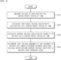
- FIG. 5 is a flowchart showing a battery diagnosis method according to an embodiment of the present invention.
- the voltage of each battery cell is measured during a preset period of time S510.
- a period of time during which the voltage of a battery cell is measured may be arbitrarily set by a user.
- Step S520 it is possible to calculate the voltage variation of each battery cell not only in a rest state in which no current flows in the battery cell but also during the charge or discharge of the battery cell.
- an average voltage variation of a plurality of battery cells during the preset period of time is calculated S530.
- the average voltage variation of all battery cells included in a specific battery pack may be calculated.
- the voltage variation of each battery cell may be calculated for a section in which the SOC of the battery cell is equal to or greater than a reference value.
- the threshold value of Step S540 may be set according to the manufacturer-specific specifications of the battery cell and a voltage measurement unit (for example, the battery management system BMS).
- the threshold value may be set in consideration of a voltage measurement error of the voltage measurement unit, a capacity error between battery cells generated during the assembly of a battery module, and the like.
- a voltage abnormality of a battery cell is diagnosed by using a voltage variation of the battery cell without a separate current sensor. Therefore, it is possible to detect an abnormality due to a sudden voltage drop of a battery not only during the charge and discharge of the battery but also in a rest state in which the voltage of the battery does not flow.
- FIG. 6 is a diagram showing a configuration of hardware according to an embodiment of the present invention.
- a battery management apparatus 600 may have a micro-controller (MCU) 610 for controlling various processing and each component, a memory 620 in which an operating system program, various programs (for example, a battery pack abnormality diagnosis program or a battery pack temperature estimation program), and the like are stored, an input/output interface 630 for providing an input interface and an output interface between a battery cell module and/or a switching unit (for example, a semiconductor switching element), and a communication interface 640 capable of communicating with the outside (for example, a higher-level controller) through a wired/wireless communication network.
- a computer program according to the present invention is stored in the memory 620 and processed by the micro-controller 610, and thus, may be implemented as, for example, a module which performs each functional block illustrated in FIG. 2 .
Landscapes
- Physics & Mathematics (AREA)
- General Physics & Mathematics (AREA)
- Engineering & Computer Science (AREA)
- Power Engineering (AREA)
- Secondary Cells (AREA)
- Charge And Discharge Circuits For Batteries Or The Like (AREA)
- Tests Of Electric Status Of Batteries (AREA)
Claims (10)
- Appareil de diagnostic de batterie (200) comprenant :une unité de mesure de tension (210) configurée pour mesurer la tension de chaque cellule de batterie pendant une période de temps prédéfinie et à un intervalle de temps prédéfini ;une unité de calcul de variation de tension (220) configurée pour calculer une variation de tension individuelle de chaque cellule de batterie correspondant à l'intervalle de temps prédéfini pendant la période de temps prédéfinie ;une unité de calcul de variation de tension moyenne (230) configurée pour calculer une variation de tension moyenne d'une pluralité de cellules de batterie pendant la période de temps prédéfinie ; etune unité de détection d'anomalie (240) configurée pour déterminer qu'une anomalie de tension s'est produite dans une cellule de batterie correspondante lorsqu'une cellule de batterie présente une différence entre la variation de tension individuelle et la variation de tension moyenne supérieure à une valeur seuil.
- Appareil de diagnostic de batterie selon la revendication 1, comprenant en outre une unité de mémoire (620) configurée pour stocker la variation de tension individuelle de chaque cellule de batterie et la variation de tension moyenne de la pluralité de cellules de batterie.
- Appareil de diagnostic de batterie selon la revendication 1, dans lequel l'unité de mesure de tension est configurée pour mesurer une variation de tension de chaque cellule de batterie pendant la charge ou la décharge de la cellule de batterie.
- Appareil de diagnostic de batterie selon la revendication 1, dans lequel l'unité de mesure de tension est configurée pour mesurer la variation de tension de la cellule de batterie dans un état dans lequel aucun courant ne circule dans la cellule de batterie, c'est-à-dire dans un état de repos.
- Appareil de diagnostic de batterie selon la revendication 1, dans lequel la valeur seuil est définie selon les spécifications spécifiques au fabricant de la cellule de batterie.
- Appareil de diagnostic de batterie selon la revendication 1, dans lequel la valeur seuil est définie selon les spécifications spécifiques au fabricant de l'unité de mesure de tension.
- Appareil de diagnostic de batterie selon la revendication 1, dans lequel la valeur seuil est de 15 mV.
- Appareil de diagnostic de batterie selon la revendication 1, dans lequel l'unité de mesure de tension est configurée pour mesurer la variation de tension de chaque cellule de batterie dans une section dans laquelle l'état de charge, SOC, de la cellule de batterie est supérieur ou égal à une valeur de référence prédéfinie.
- Appareil de diagnostic de batterie selon la revendication 1, dans lequel la valeur de référence prédéfinie est définie selon le type de cellule de batterie.
- Procédé de diagnostic de batterie comprenant :la mesure (S510) de la tension de chaque cellule de batterie pendant une période de temps prédéfinie et à un intervalle de temps prédéfini ;le calcul (S520) d'une variation de tension individuelle de chaque cellule de batterie correspondant à l'intervalle de temps prédéfini pendant la période de temps prédéfinie ;le calcul (S530) d'une variation de tension moyenne d'une pluralité de cellules de batterie pendant la période de temps prédéfinie ; etle fait de déterminer (S540) qu'une anomalie de tension s'est produite dans une cellule de batterie correspondante lorsque la différence entre la variation de tension individuelle et la variation de tension moyenne est supérieure à une valeur seuil.
Applications Claiming Priority (2)
| Application Number | Priority Date | Filing Date | Title |
|---|---|---|---|
| KR1020190113169A KR102715869B1 (ko) | 2019-09-11 | 2019-09-11 | 배터리 진단 장치 및 방법 |
| PCT/KR2020/009704 WO2021049753A1 (fr) | 2019-09-11 | 2020-07-23 | Appareil et procédé de diagnostic de batterie |
Publications (3)
| Publication Number | Publication Date |
|---|---|
| EP3958006A1 EP3958006A1 (fr) | 2022-02-23 |
| EP3958006A4 EP3958006A4 (fr) | 2022-06-01 |
| EP3958006B1 true EP3958006B1 (fr) | 2024-05-29 |
Family
ID=74867092
Family Applications (1)
| Application Number | Title | Priority Date | Filing Date |
|---|---|---|---|
| EP20862918.8A Active EP3958006B1 (fr) | 2019-09-11 | 2020-07-23 | Appareil et procédé de diagnostic de batterie |
Country Status (8)
| Country | Link |
|---|---|
| US (1) | US11965936B2 (fr) |
| EP (1) | EP3958006B1 (fr) |
| JP (1) | JP7621274B2 (fr) |
| KR (1) | KR102715869B1 (fr) |
| CN (1) | CN113811781B (fr) |
| ES (1) | ES2986194T3 (fr) |
| HU (1) | HUE066780T2 (fr) |
| WO (1) | WO2021049753A1 (fr) |
Families Citing this family (21)
| Publication number | Priority date | Publication date | Assignee | Title |
|---|---|---|---|---|
| KR102916844B1 (ko) * | 2020-08-05 | 2026-01-23 | 현대자동차주식회사 | 배터리 이상 발생 검출 장치 및 방법 |
| CN115461634B (zh) * | 2020-11-27 | 2025-10-28 | 株式会社Lg新能源 | 电池诊断装置、电池诊断方法、电池组及车辆 |
| KR20220167847A (ko) | 2021-06-14 | 2022-12-22 | 주식회사 엘지에너지솔루션 | 배터리 관리 시스템, 배터리 팩, 전기 차량 및 배터리 관리 방법 |
| KR20230010545A (ko) | 2021-07-12 | 2023-01-19 | 주식회사 엘지에너지솔루션 | 배터리 진단 장치, 배터리 팩, 전기 차량 및 배터리 진단 방법 |
| KR102918339B1 (ko) * | 2021-11-02 | 2026-01-26 | 주식회사 엘지에너지솔루션 | 저항 퇴화도에 기초한 배터리 진단 방법 및 이를 적용한 배터리 시스템 |
| KR102746845B1 (ko) * | 2021-11-19 | 2024-12-26 | 주식회사 원익피앤이 | 배터리 셀들의 결함을 판단하기 위한 장치 |
| KR102637311B1 (ko) * | 2022-01-06 | 2024-02-16 | 주식회사 엘지에너지솔루션 | 열화 배터리 셀 검출 장치 및 방법 |
| CN115061051B (zh) * | 2022-06-10 | 2024-06-07 | 重庆赛力斯新能源汽车设计院有限公司 | 一种电池电压异常的识别方法、装置、计算机设备和介质 |
| KR102864746B1 (ko) * | 2022-09-13 | 2025-09-25 | 주식회사 엘지에너지솔루션 | 배터리 관리 장치 및 그것의 동작 방법 |
| CN119816743A (zh) * | 2022-09-22 | 2025-04-11 | 株式会社Lg新能源 | 电池管理装置及其操作方法 |
| KR20240069501A (ko) * | 2022-11-11 | 2024-05-20 | 주식회사 엘지에너지솔루션 | 배터리 이상 진단 장치 및 이의 동작 방법 |
| KR102941647B1 (ko) * | 2022-11-11 | 2026-03-19 | 주식회사 엘지에너지솔루션 | 배터리 이상 진단 장치 및 이의 동작 방법 |
| KR20240069508A (ko) * | 2022-11-11 | 2024-05-20 | 주식회사 엘지에너지솔루션 | 배터리 진단 장치 및 그의 동작 방법 |
| KR20240069506A (ko) * | 2022-11-11 | 2024-05-20 | 주식회사 엘지에너지솔루션 | 배터리 진단 장치 및 그의 동작 방법 |
| KR102866791B1 (ko) * | 2022-12-09 | 2025-09-30 | 주식회사 엘지에너지솔루션 | 배터리 방전 진단 장치 및 그의 동작 방법 |
| KR20250014902A (ko) * | 2023-07-21 | 2025-02-03 | 주식회사 엘지에너지솔루션 | 배터리 진단 장치 및 이의 동작 방법 |
| KR20250024422A (ko) * | 2023-08-11 | 2025-02-18 | 주식회사 엘지에너지솔루션 | 배터리 진단 장치 및 그것의 동작 방법 |
| KR20250038375A (ko) * | 2023-09-12 | 2025-03-19 | 주식회사 엘지에너지솔루션 | 배터리 관리 장치 및 배터리 관리 방법 |
| KR102858070B1 (ko) * | 2023-10-24 | 2025-09-10 | 경북대학교 산학협력단 | 배터리 충전 전압 정보에 기반한 배터리 이상발생 판단 장치 및 방법 |
| KR20250158363A (ko) * | 2024-04-30 | 2025-11-06 | 주식회사 엘지에너지솔루션 | 배터리 관리 장치 및 그것의 동작 방법 |
| EP4726846A1 (fr) * | 2024-10-10 | 2026-04-15 | LG Energy Solution, Ltd. | Procédé d'assemblage de module de batterie et module de batterie |
Family Cites Families (45)
| Publication number | Priority date | Publication date | Assignee | Title |
|---|---|---|---|---|
| JPH05266927A (ja) | 1992-03-17 | 1993-10-15 | Matsushita Electric Ind Co Ltd | 鉛蓄電池の充電方法と、その装置 |
| JPH08126220A (ja) * | 1994-10-25 | 1996-05-17 | Toshiba Battery Co Ltd | 二次電池の充電回路 |
| ATE199797T1 (de) | 1997-11-20 | 2001-03-15 | Siemens Ag | Verfahren und vorrichtung zum überwachen einer ausgewählten gruppe von brennstoffzellen eines hochtemperatur-brennstoff-zellenstapels |
| JP2001027663A (ja) * | 1999-07-14 | 2001-01-30 | Daikin Ind Ltd | 組み電池における電池不良検出方法およびその装置 |
| KR20000054385A (ko) | 2000-06-03 | 2000-09-05 | 이홍규 | 차량의 검출 데이터를 이용하여 비교분석, 진단 및예방정비를 수행하는 음성출력 자가진단기 |
| US6744698B2 (en) * | 2001-03-08 | 2004-06-01 | Seiko Epson Corporation | Battery powered electronic device and control method therefor |
| JP4523738B2 (ja) * | 2001-06-07 | 2010-08-11 | パナソニック株式会社 | 二次電池の残存容量制御方法および装置 |
| JP4019815B2 (ja) | 2002-06-26 | 2007-12-12 | 日産自動車株式会社 | 組電池の異常診断装置および方法 |
| JP2005322456A (ja) | 2004-05-07 | 2005-11-17 | Nissan Motor Co Ltd | 異常セル検出装置 |
| JP4389758B2 (ja) * | 2004-11-04 | 2009-12-24 | 日産自動車株式会社 | セル電圧バラツキ異常検出装置 |
| JP2007010588A (ja) * | 2005-07-01 | 2007-01-18 | Sanyo Electric Co Ltd | 車両用の電源装置 |
| JP2007046942A (ja) | 2005-08-08 | 2007-02-22 | Nissan Motor Co Ltd | 電池故障判定装置 |
| JP5343299B2 (ja) | 2005-09-22 | 2013-11-13 | 日産自動車株式会社 | 電池故障検出装置 |
| JP5248764B2 (ja) | 2006-11-02 | 2013-07-31 | パナソニック株式会社 | 蓄電素子の異常検出装置、蓄電素子の異常検出方法及びその異常検出プログラム |
| JP5286708B2 (ja) * | 2007-08-03 | 2013-09-11 | トヨタ自動車株式会社 | 二次電池の異常検出装置および異常検出方法 |
| KR100985667B1 (ko) * | 2007-08-22 | 2010-10-05 | 주식회사 엘지화학 | 배터리 개방전압 추정장치, 이를 이용한 배터리 충전상태추정장치 및 그 제어 방법 |
| JP5597349B2 (ja) | 2008-04-16 | 2014-10-01 | 日産自動車株式会社 | 組電池の接続異常診断装置 |
| KR101187766B1 (ko) | 2008-08-08 | 2012-10-05 | 주식회사 엘지화학 | 배터리 셀의 전압 변화 거동을 이용한 셀 밸런싱 장치 및 방법 |
| US8350528B2 (en) | 2009-02-04 | 2013-01-08 | Samsung Sdi Co., Ltd. | Battery pack and balancing method of battery cells |
| KR101099811B1 (ko) | 2009-03-03 | 2011-12-27 | 주식회사 엘지화학 | 배터리 팩의 전류측정부 이상 진단 방법 및 장치 |
| JP5148579B2 (ja) | 2009-09-29 | 2013-02-20 | 三菱重工業株式会社 | 二次電池異常予見システム |
| US9046586B2 (en) * | 2010-03-29 | 2015-06-02 | Panasonic Intellectual Property Management Co., Ltd. | Method and device for diagnosing secondary battery degradation |
| KR101671998B1 (ko) | 2010-04-02 | 2016-11-04 | 에스케이이노베이션 주식회사 | 배터리의 용량 열화 상태 측정 장치 및 방법 |
| JP5743634B2 (ja) * | 2011-03-25 | 2015-07-01 | Necエナジーデバイス株式会社 | 劣化測定装置、二次電池パック、劣化測定方法、およびプログラム |
| CN102298119B (zh) * | 2011-05-24 | 2015-12-02 | 惠州Tcl移动通信有限公司 | 电池电量显示装置及方法 |
| US9331500B2 (en) * | 2012-04-19 | 2016-05-03 | Caterpillar Inc. | Method for balancing ultracapacitor cells |
| JP5596083B2 (ja) | 2012-06-26 | 2014-09-24 | Imv株式会社 | リチウムイオン二次電池の劣化診断装置 |
| CN103399282B (zh) * | 2013-08-07 | 2015-07-29 | 清华大学 | 电池单体故障诊断方法 |
| KR101717001B1 (ko) | 2014-07-25 | 2017-03-15 | 가부시끼가이샤 도시바 | 내부 상태 추정 시스템 및 그 추정 방법 |
| JP6471463B2 (ja) | 2014-11-06 | 2019-02-20 | 日立化成株式会社 | 蓄電池状態監視システム、蓄電池状態監視方法、および蓄電池状態監視プログラム |
| JP6468203B2 (ja) | 2016-01-13 | 2019-02-13 | トヨタ自動車株式会社 | 電源システム |
| WO2017130258A1 (fr) * | 2016-01-28 | 2017-08-03 | パナソニックIpマネジメント株式会社 | Dispositif de gestion et dispositif de stockage d'énergie |
| CN105527583B (zh) | 2016-02-05 | 2018-08-03 | 华霆(常州)动力技术有限公司 | 电池组自放电检测方法、电池组控制器及系统 |
| JP2017156268A (ja) | 2016-03-03 | 2017-09-07 | 株式会社東芝 | 電池ユニットおよび電流測定器の故障検出方法 |
| JP6555212B2 (ja) * | 2016-08-15 | 2019-08-07 | トヨタ自動車株式会社 | バッテリパックの製造方法 |
| CN108107364B (zh) * | 2016-11-24 | 2020-07-14 | 华为技术有限公司 | 一种检测电池的方法及装置 |
| KR102194845B1 (ko) | 2016-12-20 | 2020-12-23 | 주식회사 엘지화학 | 이차 전지의 저전압 불량 검사 장치 및 방법 |
| KR20180101823A (ko) * | 2017-03-06 | 2018-09-14 | 주식회사 엘지화학 | 배터리 셀 전압 데이터 처리 장치 및 방법 |
| KR101865402B1 (ko) * | 2017-03-30 | 2018-07-13 | (주)에코파워텍 | 배터리 상태 판단장치 |
| CN109435768B (zh) * | 2017-08-31 | 2024-01-09 | 比亚迪股份有限公司 | 电池均衡方法、系统、车辆、存储介质及电子设备 |
| CN110015168B (zh) * | 2017-08-31 | 2022-04-15 | 比亚迪股份有限公司 | 电池均衡方法、系统、车辆、存储介质及电子设备 |
| CN111149269B (zh) | 2017-10-04 | 2024-03-29 | 株式会社Aesc日本 | 蓄电池包的检查方法及检查装置 |
| US10698033B2 (en) | 2017-12-21 | 2020-06-30 | Robert Bosch Battery Systems, Llc | Sensor fault detection using paired sample correlation |
| CN108646183B (zh) | 2018-03-30 | 2021-01-29 | 合肥国轩高科动力能源有限公司 | 一种电池组中电池故障诊断方法 |
| US11362536B2 (en) * | 2019-06-27 | 2022-06-14 | Motorola Solutions, Inc. | Methods and apparatus for detecting open circuit faults in a battery pack containing parallel cells |
-
2019
- 2019-09-11 KR KR1020190113169A patent/KR102715869B1/ko active Active
-
2020
- 2020-07-23 ES ES20862918T patent/ES2986194T3/es active Active
- 2020-07-23 HU HUE20862918A patent/HUE066780T2/hu unknown
- 2020-07-23 WO PCT/KR2020/009704 patent/WO2021049753A1/fr not_active Ceased
- 2020-07-23 JP JP2021566061A patent/JP7621274B2/ja active Active
- 2020-07-23 US US17/607,255 patent/US11965936B2/en active Active
- 2020-07-23 CN CN202080033278.2A patent/CN113811781B/zh active Active
- 2020-07-23 EP EP20862918.8A patent/EP3958006B1/fr active Active
Also Published As
| Publication number | Publication date |
|---|---|
| KR102715869B1 (ko) | 2024-10-14 |
| WO2021049753A1 (fr) | 2021-03-18 |
| US20220229122A1 (en) | 2022-07-21 |
| US11965936B2 (en) | 2024-04-23 |
| CN113811781B (zh) | 2024-06-04 |
| CN113811781A (zh) | 2021-12-17 |
| EP3958006A4 (fr) | 2022-06-01 |
| HUE066780T2 (hu) | 2024-09-28 |
| JP2022532105A (ja) | 2022-07-13 |
| KR20210031336A (ko) | 2021-03-19 |
| EP3958006A1 (fr) | 2022-02-23 |
| JP7621274B2 (ja) | 2025-01-24 |
| ES2986194T3 (es) | 2024-11-08 |
Similar Documents
| Publication | Publication Date | Title |
|---|---|---|
| EP3958006B1 (fr) | Appareil et procédé de diagnostic de batterie | |
| EP3961233B1 (fr) | Dispositif et procédé de diagnostic de cellule de batterie | |
| US12372587B2 (en) | Battery cell diagnosing apparatus and method | |
| KR102849365B1 (ko) | 배터리 이상 진단 장치 및 방법 | |
| EP3982140B1 (fr) | Dispositif de gestion de batterie et procédé de gestion de batterie | |
| KR102927153B1 (ko) | 배터리 이상 진단 장치 및 방법 | |
| US11815558B2 (en) | Apparatus and method for diagnosing abnormal degradated battery cell | |
| EP4024066B1 (fr) | Dispositif de diagnostic de batterie, et procédé associé | |
| US20240066993A1 (en) | Battery Diagnosis Device, Battery Management System, Battery Pack, Electric Vehicle And Battery Diagnosis Method | |
| EP4484982B1 (fr) | Appareil de diagnostic de batterie, procédé de diagnostic de batterie, bloc-batterie et véhicule | |
| EP4016099B1 (fr) | Appareil et procédé de diagnostic de batterie | |
| KR20240022930A (ko) | 배터리 셀 진단 장치 및 그것의 동작 방법 | |
| KR20250097496A (ko) | 배터리 관리 장치 및 그것의 동작 방법 | |
| KR20250120700A (ko) | 배터리 진단 장치 및 그것의 동작 방법 | |
| KR20250019892A (ko) | 배터리 관리 장치 및 그것의 동작 방법 |
Legal Events
| Date | Code | Title | Description |
|---|---|---|---|
| STAA | Information on the status of an ep patent application or granted ep patent |
Free format text: STATUS: THE INTERNATIONAL PUBLICATION HAS BEEN MADE |
|
| PUAI | Public reference made under article 153(3) epc to a published international application that has entered the european phase |
Free format text: ORIGINAL CODE: 0009012 |
|
| STAA | Information on the status of an ep patent application or granted ep patent |
Free format text: STATUS: REQUEST FOR EXAMINATION WAS MADE |
|
| 17P | Request for examination filed |
Effective date: 20211119 |
|
| AK | Designated contracting states |
Kind code of ref document: A1 Designated state(s): AL AT BE BG CH CY CZ DE DK EE ES FI FR GB GR HR HU IE IS IT LI LT LU LV MC MK MT NL NO PL PT RO RS SE SI SK SM TR |
|
| RAP3 | Party data changed (applicant data changed or rights of an application transferred) |
Owner name: LG ENERGY SOLUTION, LTD. |
|
| A4 | Supplementary search report drawn up and despatched |
Effective date: 20220429 |
|
| RIC1 | Information provided on ipc code assigned before grant |
Ipc: G01R 19/165 20060101ALI20220422BHEP Ipc: G01R 31/3835 20190101ALI20220422BHEP Ipc: G01R 31/396 20190101AFI20220422BHEP |
|
| DAV | Request for validation of the european patent (deleted) | ||
| DAX | Request for extension of the european patent (deleted) | ||
| GRAP | Despatch of communication of intention to grant a patent |
Free format text: ORIGINAL CODE: EPIDOSNIGR1 |
|
| STAA | Information on the status of an ep patent application or granted ep patent |
Free format text: STATUS: GRANT OF PATENT IS INTENDED |
|
| INTG | Intention to grant announced |
Effective date: 20240307 |
|
| GRAS | Grant fee paid |
Free format text: ORIGINAL CODE: EPIDOSNIGR3 |
|
| GRAA | (expected) grant |
Free format text: ORIGINAL CODE: 0009210 |
|
| STAA | Information on the status of an ep patent application or granted ep patent |
Free format text: STATUS: THE PATENT HAS BEEN GRANTED |
|
| P01 | Opt-out of the competence of the unified patent court (upc) registered |
Effective date: 20240404 |
|
| AK | Designated contracting states |
Kind code of ref document: B1 Designated state(s): AL AT BE BG CH CY CZ DE DK EE ES FI FR GB GR HR HU IE IS IT LI LT LU LV MC MK MT NL NO PL PT RO RS SE SI SK SM TR |
|
| REG | Reference to a national code |
Ref country code: CH Ref legal event code: EP |
|
| REG | Reference to a national code |
Ref country code: IE Ref legal event code: FG4D |
|
| REG | Reference to a national code |
Ref country code: DE Ref legal event code: R096 Ref document number: 602020031803 Country of ref document: DE |
|
| REG | Reference to a national code |
Ref country code: LT Ref legal event code: MG9D |
|
| REG | Reference to a national code |
Ref country code: HU Ref legal event code: AG4A Ref document number: E066780 Country of ref document: HU |
|
| REG | Reference to a national code |
Ref country code: NL Ref legal event code: MP Effective date: 20240529 |
|
| PG25 | Lapsed in a contracting state [announced via postgrant information from national office to epo] |
Ref country code: IS Free format text: LAPSE BECAUSE OF FAILURE TO SUBMIT A TRANSLATION OF THE DESCRIPTION OR TO PAY THE FEE WITHIN THE PRESCRIBED TIME-LIMIT Effective date: 20240929 |
|
| PG25 | Lapsed in a contracting state [announced via postgrant information from national office to epo] |
Ref country code: BG Free format text: LAPSE BECAUSE OF FAILURE TO SUBMIT A TRANSLATION OF THE DESCRIPTION OR TO PAY THE FEE WITHIN THE PRESCRIBED TIME-LIMIT Effective date: 20240529 |
|
| PG25 | Lapsed in a contracting state [announced via postgrant information from national office to epo] |
Ref country code: HR Free format text: LAPSE BECAUSE OF FAILURE TO SUBMIT A TRANSLATION OF THE DESCRIPTION OR TO PAY THE FEE WITHIN THE PRESCRIBED TIME-LIMIT Effective date: 20240529 Ref country code: FI Free format text: LAPSE BECAUSE OF FAILURE TO SUBMIT A TRANSLATION OF THE DESCRIPTION OR TO PAY THE FEE WITHIN THE PRESCRIBED TIME-LIMIT Effective date: 20240529 |
|
| PG25 | Lapsed in a contracting state [announced via postgrant information from national office to epo] |
Ref country code: GR Free format text: LAPSE BECAUSE OF FAILURE TO SUBMIT A TRANSLATION OF THE DESCRIPTION OR TO PAY THE FEE WITHIN THE PRESCRIBED TIME-LIMIT Effective date: 20240830 |
|
| REG | Reference to a national code |
Ref country code: AT Ref legal event code: MK05 Ref document number: 1691084 Country of ref document: AT Kind code of ref document: T Effective date: 20240529 |
|
| PG25 | Lapsed in a contracting state [announced via postgrant information from national office to epo] |
Ref country code: AT Free format text: LAPSE BECAUSE OF FAILURE TO SUBMIT A TRANSLATION OF THE DESCRIPTION OR TO PAY THE FEE WITHIN THE PRESCRIBED TIME-LIMIT Effective date: 20240529 |
|
| PG25 | Lapsed in a contracting state [announced via postgrant information from national office to epo] |
Ref country code: PL Free format text: LAPSE BECAUSE OF FAILURE TO SUBMIT A TRANSLATION OF THE DESCRIPTION OR TO PAY THE FEE WITHIN THE PRESCRIBED TIME-LIMIT Effective date: 20240529 |
|
| PG25 | Lapsed in a contracting state [announced via postgrant information from national office to epo] |
Ref country code: LV Free format text: LAPSE BECAUSE OF FAILURE TO SUBMIT A TRANSLATION OF THE DESCRIPTION OR TO PAY THE FEE WITHIN THE PRESCRIBED TIME-LIMIT Effective date: 20240529 |
|
| PG25 | Lapsed in a contracting state [announced via postgrant information from national office to epo] |
Ref country code: PL Free format text: LAPSE BECAUSE OF FAILURE TO SUBMIT A TRANSLATION OF THE DESCRIPTION OR TO PAY THE FEE WITHIN THE PRESCRIBED TIME-LIMIT Effective date: 20240529 Ref country code: NO Free format text: LAPSE BECAUSE OF FAILURE TO SUBMIT A TRANSLATION OF THE DESCRIPTION OR TO PAY THE FEE WITHIN THE PRESCRIBED TIME-LIMIT Effective date: 20240829 Ref country code: LV Free format text: LAPSE BECAUSE OF FAILURE TO SUBMIT A TRANSLATION OF THE DESCRIPTION OR TO PAY THE FEE WITHIN THE PRESCRIBED TIME-LIMIT Effective date: 20240529 Ref country code: IS Free format text: LAPSE BECAUSE OF FAILURE TO SUBMIT A TRANSLATION OF THE DESCRIPTION OR TO PAY THE FEE WITHIN THE PRESCRIBED TIME-LIMIT Effective date: 20240929 Ref country code: HR Free format text: LAPSE BECAUSE OF FAILURE TO SUBMIT A TRANSLATION OF THE DESCRIPTION OR TO PAY THE FEE WITHIN THE PRESCRIBED TIME-LIMIT Effective date: 20240529 Ref country code: GR Free format text: LAPSE BECAUSE OF FAILURE TO SUBMIT A TRANSLATION OF THE DESCRIPTION OR TO PAY THE FEE WITHIN THE PRESCRIBED TIME-LIMIT Effective date: 20240830 Ref country code: FI Free format text: LAPSE BECAUSE OF FAILURE TO SUBMIT A TRANSLATION OF THE DESCRIPTION OR TO PAY THE FEE WITHIN THE PRESCRIBED TIME-LIMIT Effective date: 20240529 Ref country code: BG Free format text: LAPSE BECAUSE OF FAILURE TO SUBMIT A TRANSLATION OF THE DESCRIPTION OR TO PAY THE FEE WITHIN THE PRESCRIBED TIME-LIMIT Effective date: 20240529 Ref country code: AT Free format text: LAPSE BECAUSE OF FAILURE TO SUBMIT A TRANSLATION OF THE DESCRIPTION OR TO PAY THE FEE WITHIN THE PRESCRIBED TIME-LIMIT Effective date: 20240529 Ref country code: RS Free format text: LAPSE BECAUSE OF FAILURE TO SUBMIT A TRANSLATION OF THE DESCRIPTION OR TO PAY THE FEE WITHIN THE PRESCRIBED TIME-LIMIT Effective date: 20240829 |
|
| REG | Reference to a national code |
Ref country code: ES Ref legal event code: FG2A Ref document number: 2986194 Country of ref document: ES Kind code of ref document: T3 Effective date: 20241108 |
|
| PG25 | Lapsed in a contracting state [announced via postgrant information from national office to epo] |
Ref country code: NL Free format text: LAPSE BECAUSE OF FAILURE TO SUBMIT A TRANSLATION OF THE DESCRIPTION OR TO PAY THE FEE WITHIN THE PRESCRIBED TIME-LIMIT Effective date: 20240529 |
|
| PG25 | Lapsed in a contracting state [announced via postgrant information from national office to epo] |
Ref country code: NL Free format text: LAPSE BECAUSE OF FAILURE TO SUBMIT A TRANSLATION OF THE DESCRIPTION OR TO PAY THE FEE WITHIN THE PRESCRIBED TIME-LIMIT Effective date: 20240529 |
|
| PG25 | Lapsed in a contracting state [announced via postgrant information from national office to epo] |
Ref country code: DK Free format text: LAPSE BECAUSE OF FAILURE TO SUBMIT A TRANSLATION OF THE DESCRIPTION OR TO PAY THE FEE WITHIN THE PRESCRIBED TIME-LIMIT Effective date: 20240529 |
|
| PG25 | Lapsed in a contracting state [announced via postgrant information from national office to epo] |
Ref country code: EE Free format text: LAPSE BECAUSE OF FAILURE TO SUBMIT A TRANSLATION OF THE DESCRIPTION OR TO PAY THE FEE WITHIN THE PRESCRIBED TIME-LIMIT Effective date: 20240529 |
|
| PG25 | Lapsed in a contracting state [announced via postgrant information from national office to epo] |
Ref country code: CZ Free format text: LAPSE BECAUSE OF FAILURE TO SUBMIT A TRANSLATION OF THE DESCRIPTION OR TO PAY THE FEE WITHIN THE PRESCRIBED TIME-LIMIT Effective date: 20240529 |
|
| PG25 | Lapsed in a contracting state [announced via postgrant information from national office to epo] |
Ref country code: SK Free format text: LAPSE BECAUSE OF FAILURE TO SUBMIT A TRANSLATION OF THE DESCRIPTION OR TO PAY THE FEE WITHIN THE PRESCRIBED TIME-LIMIT Effective date: 20240529 Ref country code: RO Free format text: LAPSE BECAUSE OF FAILURE TO SUBMIT A TRANSLATION OF THE DESCRIPTION OR TO PAY THE FEE WITHIN THE PRESCRIBED TIME-LIMIT Effective date: 20240529 |
|
| PG25 | Lapsed in a contracting state [announced via postgrant information from national office to epo] |
Ref country code: SM Free format text: LAPSE BECAUSE OF FAILURE TO SUBMIT A TRANSLATION OF THE DESCRIPTION OR TO PAY THE FEE WITHIN THE PRESCRIBED TIME-LIMIT Effective date: 20240529 |
|
| PG25 | Lapsed in a contracting state [announced via postgrant information from national office to epo] |
Ref country code: SM Free format text: LAPSE BECAUSE OF FAILURE TO SUBMIT A TRANSLATION OF THE DESCRIPTION OR TO PAY THE FEE WITHIN THE PRESCRIBED TIME-LIMIT Effective date: 20240529 Ref country code: SK Free format text: LAPSE BECAUSE OF FAILURE TO SUBMIT A TRANSLATION OF THE DESCRIPTION OR TO PAY THE FEE WITHIN THE PRESCRIBED TIME-LIMIT Effective date: 20240529 Ref country code: RO Free format text: LAPSE BECAUSE OF FAILURE TO SUBMIT A TRANSLATION OF THE DESCRIPTION OR TO PAY THE FEE WITHIN THE PRESCRIBED TIME-LIMIT Effective date: 20240529 Ref country code: EE Free format text: LAPSE BECAUSE OF FAILURE TO SUBMIT A TRANSLATION OF THE DESCRIPTION OR TO PAY THE FEE WITHIN THE PRESCRIBED TIME-LIMIT Effective date: 20240529 Ref country code: DK Free format text: LAPSE BECAUSE OF FAILURE TO SUBMIT A TRANSLATION OF THE DESCRIPTION OR TO PAY THE FEE WITHIN THE PRESCRIBED TIME-LIMIT Effective date: 20240529 Ref country code: CZ Free format text: LAPSE BECAUSE OF FAILURE TO SUBMIT A TRANSLATION OF THE DESCRIPTION OR TO PAY THE FEE WITHIN THE PRESCRIBED TIME-LIMIT Effective date: 20240529 |
|
| PG25 | Lapsed in a contracting state [announced via postgrant information from national office to epo] |
Ref country code: IT Free format text: LAPSE BECAUSE OF FAILURE TO SUBMIT A TRANSLATION OF THE DESCRIPTION OR TO PAY THE FEE WITHIN THE PRESCRIBED TIME-LIMIT Effective date: 20240529 Ref country code: MC Free format text: LAPSE BECAUSE OF FAILURE TO SUBMIT A TRANSLATION OF THE DESCRIPTION OR TO PAY THE FEE WITHIN THE PRESCRIBED TIME-LIMIT Effective date: 20240529 |
|
| REG | Reference to a national code |
Ref country code: CH Ref legal event code: PL |
|
| REG | Reference to a national code |
Ref country code: DE Ref legal event code: R097 Ref document number: 602020031803 Country of ref document: DE |
|
| PG25 | Lapsed in a contracting state [announced via postgrant information from national office to epo] |
Ref country code: LU Free format text: LAPSE BECAUSE OF NON-PAYMENT OF DUE FEES Effective date: 20240723 |
|
| PG25 | Lapsed in a contracting state [announced via postgrant information from national office to epo] |
Ref country code: LU Free format text: LAPSE BECAUSE OF NON-PAYMENT OF DUE FEES Effective date: 20240723 |
|
| PLBE | No opposition filed within time limit |
Free format text: ORIGINAL CODE: 0009261 |
|
| STAA | Information on the status of an ep patent application or granted ep patent |
Free format text: STATUS: NO OPPOSITION FILED WITHIN TIME LIMIT |
|
| PG25 | Lapsed in a contracting state [announced via postgrant information from national office to epo] |
Ref country code: SI Free format text: LAPSE BECAUSE OF FAILURE TO SUBMIT A TRANSLATION OF THE DESCRIPTION OR TO PAY THE FEE WITHIN THE PRESCRIBED TIME-LIMIT Effective date: 20240529 Ref country code: BE Free format text: LAPSE BECAUSE OF NON-PAYMENT OF DUE FEES Effective date: 20240731 Ref country code: CH Free format text: LAPSE BECAUSE OF NON-PAYMENT OF DUE FEES Effective date: 20240731 |
|
| 26N | No opposition filed |
Effective date: 20250303 |
|
| REG | Reference to a national code |
Ref country code: BE Ref legal event code: MM Effective date: 20240731 |
|
| PGFP | Annual fee paid to national office [announced via postgrant information from national office to epo] |
Ref country code: GB Payment date: 20250624 Year of fee payment: 6 |
|
| PGFP | Annual fee paid to national office [announced via postgrant information from national office to epo] |
Ref country code: FR Payment date: 20250624 Year of fee payment: 6 |
|
| PG25 | Lapsed in a contracting state [announced via postgrant information from national office to epo] |
Ref country code: IE Free format text: LAPSE BECAUSE OF NON-PAYMENT OF DUE FEES Effective date: 20240723 |
|
| PGFP | Annual fee paid to national office [announced via postgrant information from national office to epo] |
Ref country code: HU Payment date: 20250721 Year of fee payment: 6 |
|
| PG25 | Lapsed in a contracting state [announced via postgrant information from national office to epo] |
Ref country code: SE Free format text: LAPSE BECAUSE OF FAILURE TO SUBMIT A TRANSLATION OF THE DESCRIPTION OR TO PAY THE FEE WITHIN THE PRESCRIBED TIME-LIMIT Effective date: 20240529 |
|
| PGFP | Annual fee paid to national office [announced via postgrant information from national office to epo] |
Ref country code: ES Payment date: 20250822 Year of fee payment: 6 |
|
| PGFP | Annual fee paid to national office [announced via postgrant information from national office to epo] |
Ref country code: DE Payment date: 20250624 Year of fee payment: 6 |
|
| PG25 | Lapsed in a contracting state [announced via postgrant information from national office to epo] |
Ref country code: PT Free format text: LAPSE BECAUSE OF NON-PAYMENT OF DUE FEES Effective date: 20240529 |
|
| PG25 | Lapsed in a contracting state [announced via postgrant information from national office to epo] |
Ref country code: CY Free format text: LAPSE BECAUSE OF FAILURE TO SUBMIT A TRANSLATION OF THE DESCRIPTION OR TO PAY THE FEE WITHIN THE PRESCRIBED TIME-LIMIT; INVALID AB INITIO Effective date: 20200723 |