EP3958320A1 - Anzeigevorrichtung - Google Patents
Anzeigevorrichtung Download PDFInfo
- Publication number
- EP3958320A1 EP3958320A1 EP20878636.8A EP20878636A EP3958320A1 EP 3958320 A1 EP3958320 A1 EP 3958320A1 EP 20878636 A EP20878636 A EP 20878636A EP 3958320 A1 EP3958320 A1 EP 3958320A1
- Authority
- EP
- European Patent Office
- Prior art keywords
- light
- display device
- display panel
- layer
- cover plate
- Prior art date
- Legal status (The legal status is an assumption and is not a legal conclusion. Google has not performed a legal analysis and makes no representation as to the accuracy of the status listed.)
- Granted
Links
Images


Classifications
-
- H—ELECTRICITY
- H10—SEMICONDUCTOR DEVICES; ELECTRIC SOLID-STATE DEVICES NOT OTHERWISE PROVIDED FOR
- H10K—ORGANIC ELECTRIC SOLID-STATE DEVICES
- H10K59/00—Integrated devices, or assemblies of multiple devices, comprising at least one organic light-emitting element covered by group H10K50/00
- H10K59/10—OLED displays
- H10K59/12—Active-matrix OLED [AMOLED] displays
- H10K59/126—Shielding, e.g. light-blocking means over the TFTs
-
- G—PHYSICS
- G09—EDUCATION; CRYPTOGRAPHY; DISPLAY; ADVERTISING; SEALS
- G09F—DISPLAYING; ADVERTISING; SIGNS; LABELS OR NAME-PLATES; SEALS
- G09F9/00—Indicating arrangements for variable information in which the information is built-up on a support by selection or combination of individual elements
- G09F9/30—Indicating arrangements for variable information in which the information is built-up on a support by selection or combination of individual elements in which the desired character or characters are formed by combining individual elements
-
- H—ELECTRICITY
- H10—SEMICONDUCTOR DEVICES; ELECTRIC SOLID-STATE DEVICES NOT OTHERWISE PROVIDED FOR
- H10K—ORGANIC ELECTRIC SOLID-STATE DEVICES
- H10K59/00—Integrated devices, or assemblies of multiple devices, comprising at least one organic light-emitting element covered by group H10K50/00
- H10K59/80—Constructional details
- H10K59/8791—Arrangements for improving contrast, e.g. preventing reflection of ambient light
- H10K59/8792—Arrangements for improving contrast, e.g. preventing reflection of ambient light comprising light absorbing layers, e.g. black layers
-
- H—ELECTRICITY
- H10—SEMICONDUCTOR DEVICES; ELECTRIC SOLID-STATE DEVICES NOT OTHERWISE PROVIDED FOR
- H10K—ORGANIC ELECTRIC SOLID-STATE DEVICES
- H10K50/00—Organic light-emitting devices
- H10K50/80—Constructional details
- H10K50/84—Passivation; Containers; Encapsulations
- H10K50/841—Self-supporting sealing arrangements
-
- H—ELECTRICITY
- H10—SEMICONDUCTOR DEVICES; ELECTRIC SOLID-STATE DEVICES NOT OTHERWISE PROVIDED FOR
- H10K—ORGANIC ELECTRIC SOLID-STATE DEVICES
- H10K50/00—Organic light-emitting devices
- H10K50/80—Constructional details
- H10K50/84—Passivation; Containers; Encapsulations
- H10K50/844—Encapsulations
-
- H—ELECTRICITY
- H10—SEMICONDUCTOR DEVICES; ELECTRIC SOLID-STATE DEVICES NOT OTHERWISE PROVIDED FOR
- H10K—ORGANIC ELECTRIC SOLID-STATE DEVICES
- H10K50/00—Organic light-emitting devices
- H10K50/80—Constructional details
- H10K50/85—Arrangements for extracting light from the devices
- H10K50/854—Arrangements for extracting light from the devices comprising scattering means
-
- H—ELECTRICITY
- H10—SEMICONDUCTOR DEVICES; ELECTRIC SOLID-STATE DEVICES NOT OTHERWISE PROVIDED FOR
- H10K—ORGANIC ELECTRIC SOLID-STATE DEVICES
- H10K59/00—Integrated devices, or assemblies of multiple devices, comprising at least one organic light-emitting element covered by group H10K50/00
- H10K59/10—OLED displays
- H10K59/12—Active-matrix OLED [AMOLED] displays
- H10K59/121—Active-matrix OLED [AMOLED] displays characterised by the geometry or disposition of pixel elements
-
- H—ELECTRICITY
- H10—SEMICONDUCTOR DEVICES; ELECTRIC SOLID-STATE DEVICES NOT OTHERWISE PROVIDED FOR
- H10K—ORGANIC ELECTRIC SOLID-STATE DEVICES
- H10K59/00—Integrated devices, or assemblies of multiple devices, comprising at least one organic light-emitting element covered by group H10K50/00
- H10K59/80—Constructional details
- H10K59/875—Arrangements for extracting light from the devices
- H10K59/877—Arrangements for extracting light from the devices comprising scattering means
-
- H—ELECTRICITY
- H10—SEMICONDUCTOR DEVICES; ELECTRIC SOLID-STATE DEVICES NOT OTHERWISE PROVIDED FOR
- H10K—ORGANIC ELECTRIC SOLID-STATE DEVICES
- H10K59/00—Integrated devices, or assemblies of multiple devices, comprising at least one organic light-emitting element covered by group H10K50/00
- H10K59/80—Constructional details
- H10K59/875—Arrangements for extracting light from the devices
- H10K59/878—Arrangements for extracting light from the devices comprising reflective means
-
- H—ELECTRICITY
- H10—SEMICONDUCTOR DEVICES; ELECTRIC SOLID-STATE DEVICES NOT OTHERWISE PROVIDED FOR
- H10K—ORGANIC ELECTRIC SOLID-STATE DEVICES
- H10K59/00—Integrated devices, or assemblies of multiple devices, comprising at least one organic light-emitting element covered by group H10K50/00
- H10K59/80—Constructional details
- H10K59/875—Arrangements for extracting light from the devices
- H10K59/879—Arrangements for extracting light from the devices comprising refractive means, e.g. lenses
-
- H—ELECTRICITY
- H10—SEMICONDUCTOR DEVICES; ELECTRIC SOLID-STATE DEVICES NOT OTHERWISE PROVIDED FOR
- H10K—ORGANIC ELECTRIC SOLID-STATE DEVICES
- H10K59/00—Integrated devices, or assemblies of multiple devices, comprising at least one organic light-emitting element covered by group H10K50/00
- H10K59/60—OLEDs integrated with inorganic light-sensitive elements, e.g. with inorganic solar cells or inorganic photodiodes
- H10K59/65—OLEDs integrated with inorganic image sensors
-
- H—ELECTRICITY
- H10—SEMICONDUCTOR DEVICES; ELECTRIC SOLID-STATE DEVICES NOT OTHERWISE PROVIDED FOR
- H10K—ORGANIC ELECTRIC SOLID-STATE DEVICES
- H10K59/00—Integrated devices, or assemblies of multiple devices, comprising at least one organic light-emitting element covered by group H10K50/00
- H10K59/80—Constructional details
- H10K59/87—Passivation; Containers; Encapsulations
- H10K59/871—Self-supporting sealing arrangements
-
- H—ELECTRICITY
- H10—SEMICONDUCTOR DEVICES; ELECTRIC SOLID-STATE DEVICES NOT OTHERWISE PROVIDED FOR
- H10K—ORGANIC ELECTRIC SOLID-STATE DEVICES
- H10K59/00—Integrated devices, or assemblies of multiple devices, comprising at least one organic light-emitting element covered by group H10K50/00
- H10K59/80—Constructional details
- H10K59/87—Passivation; Containers; Encapsulations
- H10K59/873—Encapsulations
Definitions
- the present application relates to the field of display technology, and particularly, to a display device.
- the display screen with the high screen-to-body ratio is getting more and more popular.
- a camera of the display device is disposed in the non-active area of the display screen.
- the following manner is proposed.
- the active area is notched, the component such as the camera or the telephone receiver is disposed in the notched area in the active area, and the non-active area of the display screen is canceled.
- the active area is notched, a lateral leakage of light from the organic light-emitting layer tends to occur, thus affecting the photographing effect of the camera and the display performance of the display screen.
- the exemplary embodiments disclosed by the present application provide a display device.
- a display device including a display panel and a cover plate covering the display panel.
- the display panel is provided with a through hole extending through the display panel in a thickness direction thereof.
- the display panel includes a frame area and an active area.
- the frame area surrounds the through hole.
- the active area surrounds the frame area.
- the cover plate includes a first region, a second region, and a third region.
- the first region covers the active area.
- the second region covers the frame area.
- a surface of the second region adjacent to the display panel is provided with a light-shielding portion thereon.
- the third region covers the through hole.
- the cover plate is divided into the first region, the second region, and the third region.
- the first region covers the active area
- the second region covers the frame area
- the third region covers the through hole.
- the light-shielding portion is disposed on the surface of the cover plate adjacent to the display panel, that is, the light-shielding portion is arranged around the through hole, so that the light from the active area is reflected or absorbed by the light-shielding portion, thereby changing the travel path of the light.
- the light from the active area is prevented from emitting from the through hole, thus improving the photosensitive property of the camera module and the photosensitive property of the camera module.
- the display performance of the display device may also be improved.
- a high screen-to-body ratio is the development tendency of the display panel.
- a non-active area of the display screen may be canceled, so that an area of an active area can be increased.
- the active area may be notched to form a through hole for receiving the front-facing camera module, and the front-facing camera module may be disposed in the through hole in the active area, so that the screen-to-body ratio of the display screen can be significantly increased.
- light in the notched active area may leak from the through hole, thereby affecting the photosensitive property of the camera module disposed in the through hole.
- the light leakage will also decrease the display performance of the display panel.
- the embodiments of the present application provide a display device, in which a light-shielding portion is arranged around the through hole to reflect or absorb light, and/or a light-interfering layer is arranged around the through hole to change a travel path of light, to prevent the light from leaking from the through hole, thus improving both the photosensitive property of the front-facing camera module and the display performance of the display panel.
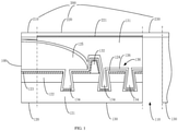
- a display device provided in an embodiment of the present application includes a display panel 100 and a cover plate 200 covering the display panel 100.
- the display panel 100 is provided with a through hole 110 going through the display panel in a thickness direction thereof.
- the display panel 100 is further provided with an active area 120 and a frame area 130, wherein the frame area 130 is surrounded by the active area 120, and the through hole 110 is surrounded by the frame area 130.
- the through hole 110 is configured to have a camera module such as a front-facing camera installed therein.
- the through hole 110 may have a cross-section having a circular shape or any other shape.
- the frame area 130 is a non-active area around the through hole 110, that is, the frame area 130 has no display function.
- the active area 120 includes a substrate 121, a pixel circuit layer 122, a light-emitting layer 123, a first inorganic layer 124, an organic layer 125, and a second inorganic layer 126.
- the first inorganic layer 124, the organic layer 125, and the second inorganic layer 126 constitute an encapsulation structure of the display panel 100.
- the frame area 130 includes the substrate 121 and an optically clear adhesive layer 131 disposed on the substrate 121.
- the substrate 121 in the frame area 130 is provided with a plurality of grooves 134 thereon.
- a protrusion 136 is provided between adjacent grooves 134.
- the grooves 134 and the protrusion 136 are deposited with the light-emitting layer 123, the first inorganic layer 124, and the second inorganic layer 126 thereon in sequence.
- the grooves 134 formed in the frame area 130 are configured to cut the light-emitting layer 123 in the active area 120 to cause the discontinuous extension of the light-emitting layer 123 in the frame area 130, so that the light-emitting layer 123 in the frame area 130 is unable to emit light.
- the grooves 134 may also be configured to disperse stress and thus preventing the fracture and the influence on the display performance.
- the frame area 130 further includes a blocking wall 132 adjacent to an edge of the encapsulation structure. The blocking wall 132 may be configured to isolate the active area from the through hole, to prevent the organic layer 125 from flowing into the through hole 110.
- the cover plate 200 may be a glass cover plate or a cover plate made of other transparent material.
- the cover plate 200 includes a first region 210, a second region 220, and a third region 230.
- the first region 210 covers the active area 120.
- the second region 220 covers the frame area 130.
- the third region 230 covers the through hole 110.
- a light-shielding portion 221 is disposed on a surface of the second region 220, which is adjacent to the display panel 100.
- a surface of the cover plate 200 adjacent to the display panel 100 is referred to as a bottom surface
- a surface of the cover plate 200 away from the display panel 100 is referred to as a top surface.
- the light-shielding portion 221 is disposed on the bottom surface of the second region 220 of the cover plate 200.
- the light from the active area 120 can be reflected by the light-shielding portion 221, so that the travel path of the light is changed, thus preventing the light from emitting from the through hole 110.
- the light-shielding portion 221 may also adsorb the light from the active area 110, to reduce the light entering the frame area 130. Therefore, the light emitting from the through hole 110 may be significantly reduced, thereby improving the photosensitive property of the camera module disposed in the through hole 110.
- the light-shielding portion 221 may cover the entire bottom surface of the second region 220, or may cover part of the bottom surface of the second region 220.
- the light-shielding portion 221 is disposed on the bottom surface of the cover plate 200 in the frame area 130 and configured to change the travel path of the light from the active area 120 and/or adsorb the light from the active area 120, thus avoiding or reducing the light emitting from the through hole 110, thereby improving the photosensitive property of the camera module in the through hole 110 and the display performance of the display panel 100.
- the roughness of the bottom surface of the second region 220 of the cover plate 200 is larger than the roughness of the bottom surface of the first region 210 and larger than the roughness of the third region 230 of the cover plate 200.
- the light-shielding portion 221 is the rough bottom surface of the second region 220. A diffuse reflection occurs when the light from the active area 120 reaches the bottom surface of the second region 220 of the cover plate 200, thus reducing the light leaking from the through hole 110, and improving the photosensitive property of the camera module and the display performance of the display device.
- the bottom surface of the second region 220 of the cover plate 200 may be preprocessed via a method such as shot blasting to increase the roughness of this bottom surface, so that the roughness of the bottom surface of the second region 220 of the cover plate 200 is larger than the roughness of the bottom surface of the first region 210 and the third region 230 of the cover plate 200.
- the light-shielding portion 221 may be a metal layer.
- the metal layer may be firstly deposited on the bottom surface of the second region 220 of the cover plate 200 and then attached to the surface of the display panel 100 together with the cover plate 200.
- the metal layer is used to form a mirror reflection of the light to disturb the travel path of the light, thus preventing the light from the active area 120 from leaking from the through hole 110.
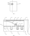
- FIG. 2 is a top view illustrating the display device provided in an embodiment of the present application.
- the display device further includes a light-interfering layer 300.
- the light-interfering layer 300 is arranged in the frame area 130 between the active area 120 and the through hole 110 and surrounds the through hole 110.
- the light-interfering layer 300 is configured to absorb the light from the active area 120 or to change the travel path of the light from the active area 120, to prevent the light from leaking from the through hole 110.
- FIG. 3 is a schematic partial sectional view illustrating the display device taken along a dotted line A-A' in the FIG. 2 .
- the light-interfering layer 300 is disposed on a top surface of the optically clear adhesive layer 131 adjacent to the cover plate 200, and configured to change the travel path of the light from the active area 120 or absorb the light from the active area 120.
- the light-interfering layer 300 may cover the entire top surface of the optically clear adhesive layer 131 or part of the top surface of the optically clear adhesive layer 131.
- the light-interfering layer 300 may be a black gum.
- the black gum may overlay the top surface of the optically clear adhesive layer 131 after the optically clear adhesive layer 131 is formed in the frame area 130.
- the black gum may overlay the bottom surface of the second region 220 of the cover plate 200, and then the cover plate 200 together with the black gum may be attached onto the surface of the display panel 100.
- the light absorption effect of the black gum is used to absorb the light from the active area 120, thereby reducing the light leaking from the through hole 110, reducing the influence of the lateral leakage of the light from the active area 120 on the photosensitive effect of the camera module disposed in the through hole 110, and improving the display performance of the display panel.
- the light-interfering layer 300 may be a prism or an organic material having a relatively high surface roughness, as long as it may change the travel path of the light from the active area 120 or may absorb the light from the active area.
- the prism may be used to refract light to change the travel path of the light
- the organic material having high surface roughness may be used to form a diffuse reflection of light to change the travel path of the light.
- the organic material having the relatively high surface roughness may be zirconium naphthenate, cobalt naphthenate, nickel naphthenate, titanium naphthenate, or the like.
- the light-interfering layer 300 is arranged in the frame area 130 between the through hole 110 and the active area 120 and disposed on the optically clear adhesive layer 131, and surrounds the through hole 110, thereby changing the travel path of the light from the active area 120 by the light-interfering layer 300 and preventing the light 120 leaking from the through hole 110, eliminating the influence of the lateral leakage of light on, for example, the photographing of the camera, and moreover, improving the display performance of the display device.
- the light-interfering layer 300 may be disposed in the optically clear adhesive layer 131. More specifically, the light-interfering layer 300 is disposed at a side in the optically clear adhesive layer 131 adjacent to the active area 120, and positioned over a location corresponding to the protrusion 136 in the frame area 130. In this embodiment, after the optically clear adhesive layer 131 is formed, a portion of the optically clear adhesive layer 131 adjacent to the active area 120 is etched to form a recess in the optically clear adhesive layer 131. Then the light-interfering layer 300 is formed in the recess.
- the light-interfering layer 300 can be a black gum.
- the black gum is arranged proximate to the active area 120 and surrounding the through hole 110, thereby realizing a better light-blocking effect, effectively preventing the light from leaking from the through hole 110, and moreover, improving the photosensitive property of the camera module and the display performance of the display device.
- FIG. 5 is a schematic partially enlarged view illustrating a sectional structure at the dotted line frame B in the FIG. 4 .
- h1 denotes a height of the light-interfering layer 300 in a direction perpendicular to the display panel 100
- h2 denotes a height of the optically clear adhesive layer 131 disposed at the location corresponding to the light-interfering layer 300, in the direction perpendicular to the display panel 100
- a relationship between the height h1 of the light-interfering layer 300 and the height h2 of the optically clear adhesive layer 131 satisfies: 0.5 ⁇ h 2 ⁇ h 1 ⁇ 0.8 ⁇ h 2 .
- the shielding and blocking effect is unsatisfying, and relatively much light leaks. If the height of the light-interfering layer 300 is too large, for example, larger than 0.8 ⁇ h2 , then a distance between an end of the light-interfering layer 300 and the second inorganic layer 126 is too small, and thus the second inorganic layer 126 tends to be damaged when the optically clear adhesive layer 131 is etched to form the groove.
- the stress at this location may be relatively large, thus causing the display panel 100 to be bent and the second inorganic layer 126 to break easily under an external stress, and affecting the encapsulation effect. Therefore, a reasonable configuration of the thickness of the light-interfering layer 300 can improve the light-blocking effect of the light-interfering layer 300 while not affecting the encapsulation effect, thereby improving the photosensitive property of the camera module and the display performance of the display device.
- FIG. 6 is a schematic sectional structural view illustrating the display panel provided in an embodiment of the present application.
- the light-interfering layer 300 may be disposed on a surface of the optically clear adhesive layer 131 adjacent to the through hole 110, that is, the light-interfering layer 300 is arranged on and surrounding an inner surface of a side wall of the through hole 110.
- the height of the light-interfering layer 300 in the direction perpendicular to the display panel 100 and the height of the optically clear adhesive layer 131 in the direction perpendicular to the display panel 100 may be identical or different.
- the height of the light-interfering layer 300 in the direction perpendicular to the display panel 100 is the same as the height of the optically clear adhesive layer 131 in the direction perpendicular to the display panel 100, a better light-blocking effect is achieved by the light-interfering layer 300, so that the photosensitive property of the camera module and the display performance of the display panel 100 are significantly improved.
- the light-interfering layer 300 may be any one of the black gum, the prism, and the organic material having a relatively high surface roughness.
- the light-interfering layer 300 can be the black gum.
- the black gum may be formed on an inner side wall of the through hole 110 while the optically clear adhesive layer 131 is being formed.
- a layer of the black gum may be formed on the side wall of the through hole 110 by using a gum-dispensing method after the optically clear adhesive layer 131 is formed.
- a light-interfering layer 300 may be formed in a circle in the third region 230 of the cover plate 200 after the cover plate 200 is formed, and a shape of the light-interfering layer 300 is consistent with a shape of the through hole 110, for example, the light-interfering layer 300 is formed in a circle at a periphery of the third region 230, that is, the light-interfering layer 300 is in a shape of a hollow cylinder.
- the height of the light-interfering layer 300 and the height of the optically clear adhesive layer 131 in the direction perpendicular to the display panel 100 are identical.
- the cover plate 200 After the light-interfering layer 300 is formed on the cover plate 200, the cover plate 200 together with the light-interfering layer 300 is attached onto the display panel 100, where the light-interfering layer 300 is attached onto the inner side wall of the through hole 110, and the components such as front-facing cameral and the handset are arranged in hollow space.
- the light-interfering layer 300 is arranged in a circle on the inner side wall of the through hole 100 of the display device, so that the light from the display panel 120 may be blocked, or the travel path of the light is changed, and no light can laterally leak to the through hole and be transmitted outwards, thus improving the photosensitive property of the camera module and the display performance of the display panel 100.
Landscapes
- Physics & Mathematics (AREA)
- Engineering & Computer Science (AREA)
- Optics & Photonics (AREA)
- Microelectronics & Electronic Packaging (AREA)
- Geometry (AREA)
- Devices For Indicating Variable Information By Combining Individual Elements (AREA)
- Theoretical Computer Science (AREA)
- General Physics & Mathematics (AREA)
- Electroluminescent Light Sources (AREA)
- Chemical & Material Sciences (AREA)
- Inorganic Chemistry (AREA)
- Life Sciences & Earth Sciences (AREA)
- Sustainable Development (AREA)
Applications Claiming Priority (2)
| Application Number | Priority Date | Filing Date | Title |
|---|---|---|---|
| CN201911000579.0A CN110634410A (zh) | 2019-10-21 | 2019-10-21 | 显示装置 |
| PCT/CN2020/102795 WO2021077821A1 (zh) | 2019-10-21 | 2020-07-17 | 显示装置 |
Publications (3)
| Publication Number | Publication Date |
|---|---|
| EP3958320A1 true EP3958320A1 (de) | 2022-02-23 |
| EP3958320A4 EP3958320A4 (de) | 2022-08-24 |
| EP3958320B1 EP3958320B1 (de) | 2025-07-02 |
Family
ID=68976951
Family Applications (1)
| Application Number | Title | Priority Date | Filing Date |
|---|---|---|---|
| EP20878636.8A Active EP3958320B1 (de) | 2019-10-21 | 2020-07-17 | Anzeigevorrichtung |
Country Status (6)
| Country | Link |
|---|---|
| US (1) | US12058902B2 (de) |
| EP (1) | EP3958320B1 (de) |
| JP (1) | JP7289935B2 (de) |
| KR (1) | KR102648558B1 (de) |
| CN (1) | CN110634410A (de) |
| WO (1) | WO2021077821A1 (de) |
Families Citing this family (14)
| Publication number | Priority date | Publication date | Assignee | Title |
|---|---|---|---|---|
| CN110634410A (zh) | 2019-10-21 | 2019-12-31 | 昆山国显光电有限公司 | 显示装置 |
| CN111081751B (zh) * | 2020-01-02 | 2023-01-24 | 京东方科技集团股份有限公司 | 一种显示装置及其制作方法 |
| KR102742772B1 (ko) * | 2020-02-13 | 2024-12-13 | 삼성디스플레이 주식회사 | 표시 장치 |
| KR102799087B1 (ko) * | 2020-03-19 | 2025-04-24 | 삼성디스플레이 주식회사 | 표시 장치 |
| CN115362554B (zh) * | 2020-04-08 | 2025-03-14 | 高通股份有限公司 | 针对显示面板的切口区域生成动态虚拟遮罩层 |
| CN111540271B (zh) * | 2020-05-18 | 2022-06-17 | 昆山国显光电有限公司 | 显示面板和显示装置 |
| US11600800B2 (en) * | 2020-07-31 | 2023-03-07 | Innolux Corporation | Electronic device having a curved profile interface corresponding to a recess |
| JP2022072381A (ja) * | 2020-10-29 | 2022-05-17 | 東京エレクトロン株式会社 | 有機elパネルの製造方法及び有機elパネル |
| JP7442419B2 (ja) * | 2020-10-29 | 2024-03-04 | 東京エレクトロン株式会社 | 有機elパネルの製造方法 |
| KR20220082167A (ko) * | 2020-12-09 | 2022-06-17 | 삼성디스플레이 주식회사 | 표시 장치 및 그 제조 방법 |
| CN113888961B (zh) | 2021-03-05 | 2022-08-12 | 荣耀终端有限公司 | 一种具有折叠屏的电子设备及控制方法 |
| CN113921572B (zh) * | 2021-09-29 | 2025-04-29 | 湖北长江新型显示产业创新中心有限公司 | 显示面板及显示装置 |
| KR20230103186A (ko) * | 2021-12-31 | 2023-07-07 | 엘지디스플레이 주식회사 | 표시 장치 |
| CN116390597A (zh) * | 2023-04-25 | 2023-07-04 | 合肥维信诺科技有限公司 | 显示面板、显示装置及显示面板的制备方法 |
Family Cites Families (37)
| Publication number | Priority date | Publication date | Assignee | Title |
|---|---|---|---|---|
| CN100454103C (zh) | 2005-06-01 | 2009-01-21 | 友达光电股份有限公司 | 具防止漏光功能的液晶显示器及其背光模块 |
| CN101652803B (zh) * | 2007-04-03 | 2015-02-04 | 迪睿合电子材料有限公司 | 图像显示装置的制造方法 |
| US8355093B2 (en) | 2010-03-16 | 2013-01-15 | Lg Electronics Inc. | Backlight unit and display device |
| CN102661574B (zh) * | 2012-04-28 | 2014-05-21 | 深圳市华星光电技术有限公司 | 导光板及具有该导光板的背光模组 |
| JP6070026B2 (ja) * | 2012-10-02 | 2017-02-01 | 大日本印刷株式会社 | 有機el表示装置 |
| WO2015033721A1 (ja) * | 2013-09-04 | 2015-03-12 | シャープ株式会社 | 表示パネル |
| KR102248240B1 (ko) * | 2014-02-11 | 2021-05-06 | 삼성디스플레이 주식회사 | 표시장치 및 그 제조방법 |
| KR102524754B1 (ko) * | 2015-09-09 | 2023-04-21 | 엘지디스플레이 주식회사 | 표시 장치 |
| KR102421577B1 (ko) * | 2016-04-05 | 2022-07-18 | 삼성디스플레이 주식회사 | 디스플레이 장치 |
| KR102587768B1 (ko) * | 2017-02-24 | 2023-10-12 | 삼성디스플레이 주식회사 | 표시 장치 |
| KR102362598B1 (ko) * | 2017-08-08 | 2022-02-14 | 삼성디스플레이 주식회사 | 인쇄회로기판 및 이를 포함하는 표시 장치 |
| CN107632453B (zh) * | 2017-10-31 | 2021-03-02 | 京东方科技集团股份有限公司 | 显示面板及制造方法和显示装置 |
| JP2019082594A (ja) * | 2017-10-31 | 2019-05-30 | ソニー株式会社 | 表示装置 |
| CN207676585U (zh) * | 2017-12-06 | 2018-07-31 | 深圳雷曼光电科技股份有限公司 | Led显示装置 |
| KR102482534B1 (ko) * | 2017-12-19 | 2022-12-28 | 엘지디스플레이 주식회사 | 유기 발광 표시 장치 및 그의 제조방법 |
| KR102527993B1 (ko) * | 2018-01-05 | 2023-05-04 | 삼성디스플레이 주식회사 | 표시장치 및 그의 제조방법 |
| KR102520016B1 (ko) * | 2018-02-02 | 2023-04-11 | 삼성디스플레이 주식회사 | 표시 패널 및 이를 포함하는 전자 장치 |
| US10620665B2 (en) * | 2018-02-05 | 2020-04-14 | Guangdong Oppo Mobile Telecommunications Corp., Lt | Terminal display assembly and mobile terminal |
| KR102405146B1 (ko) * | 2018-02-08 | 2022-06-08 | 삼성디스플레이 주식회사 | 유기 발광 표시 장치 및 이의 제조 방법 |
| US10991774B2 (en) * | 2018-02-12 | 2021-04-27 | Samsung Display Co., Ltd. | Display device and method for fabricating the same |
| CN108919545B (zh) * | 2018-06-28 | 2021-05-04 | 厦门天马微电子有限公司 | 一种显示面板及显示装置 |
| CN108845450B (zh) * | 2018-06-29 | 2021-06-04 | Oppo广东移动通信有限公司 | 显示组件和电子设备 |
| CN108826103B (zh) * | 2018-06-29 | 2020-12-25 | 厦门天马微电子有限公司 | 一种显示装置 |
| CN108957829A (zh) * | 2018-07-06 | 2018-12-07 | Oppo广东移动通信有限公司 | 显示屏组件、电子设备及电子设备的制作方法 |
| CN108681131B (zh) * | 2018-07-27 | 2021-07-30 | 厦门天马微电子有限公司 | 显示装置 |
| CN109031756A (zh) * | 2018-08-01 | 2018-12-18 | 厦门天马微电子有限公司 | 一种显示装置及移动终端 |
| CN109040380B (zh) * | 2018-09-29 | 2024-11-01 | 西安易朴通讯技术有限公司 | 一种显示装置及移动终端 |
| CN208782856U (zh) * | 2018-09-29 | 2019-04-23 | 西安易朴通讯技术有限公司 | 一种显示装置及移动终端 |
| CN109545826B (zh) * | 2018-11-19 | 2020-12-22 | 上海天马微电子有限公司 | 一种显示面板、其制造方法及包含其的显示装置 |
| KR102570864B1 (ko) * | 2018-11-29 | 2023-08-28 | 삼성디스플레이 주식회사 | 전자 장치 |
| KR102763274B1 (ko) * | 2018-11-30 | 2025-02-10 | 삼성디스플레이 주식회사 | 표시장치 |
| CN109671864B (zh) * | 2018-12-20 | 2020-06-30 | 武汉华星光电技术有限公司 | Oled显示面板 |
| CN109887410B (zh) * | 2019-03-28 | 2021-03-12 | 厦门天马微电子有限公司 | 一种显示装置及显示装置的制作方法 |
| CN110120996B (zh) * | 2019-06-06 | 2021-04-27 | Oppo广东移动通信有限公司 | Oled通孔屏、移动终端、摄像控制方法、装置及存储介质 |
| WO2020258262A1 (zh) * | 2019-06-28 | 2020-12-30 | 京东方科技集团股份有限公司 | 显示面板及其制备方法、显示装置 |
| KR102820737B1 (ko) * | 2019-10-02 | 2025-06-16 | 삼성디스플레이 주식회사 | 표시 장치 |
| CN110634410A (zh) * | 2019-10-21 | 2019-12-31 | 昆山国显光电有限公司 | 显示装置 |
-
2019
- 2019-10-21 CN CN201911000579.0A patent/CN110634410A/zh active Pending
-
2020
- 2020-07-17 KR KR1020217037844A patent/KR102648558B1/ko active Active
- 2020-07-17 EP EP20878636.8A patent/EP3958320B1/de active Active
- 2020-07-17 JP JP2021569094A patent/JP7289935B2/ja active Active
- 2020-07-17 WO PCT/CN2020/102795 patent/WO2021077821A1/zh not_active Ceased
-
2021
- 2021-10-18 US US17/504,224 patent/US12058902B2/en active Active
Also Published As
| Publication number | Publication date |
|---|---|
| EP3958320B1 (de) | 2025-07-02 |
| KR102648558B1 (ko) | 2024-03-18 |
| EP3958320A4 (de) | 2022-08-24 |
| KR20210148362A (ko) | 2021-12-07 |
| WO2021077821A1 (zh) | 2021-04-29 |
| JP7289935B2 (ja) | 2023-06-12 |
| JP2022533229A (ja) | 2022-07-21 |
| US12058902B2 (en) | 2024-08-06 |
| CN110634410A (zh) | 2019-12-31 |
| US20220037442A1 (en) | 2022-02-03 |
Similar Documents
| Publication | Publication Date | Title |
|---|---|---|
| EP3958320B1 (de) | Anzeigevorrichtung | |
| CN110853507B (zh) | 一种显示屏和电子设备 | |
| CN109100892B (zh) | 一种液晶显示面板及显示装置 | |
| CN111863868B (zh) | 屏下摄像组件及相应的有机发光二极管显示屏和终端设备 | |
| CN107229148B (zh) | 显示屏、显示装置及移动终端 | |
| EP3522504B1 (de) | Endgeräteanzeigeanordnung und mobiles endgerät | |
| CN108919545B (zh) | 一种显示面板及显示装置 | |
| KR20200063189A (ko) | 단말기 디스플레이 어셈블리 및 이동 단말기 | |
| US11556024B2 (en) | Display assembly of electronic device, electronic device, and method for manufacturing display assembly | |
| US20230081014A1 (en) | Display module and display device | |
| JP5652807B2 (ja) | 携帯機器におけるバックライト方式の表示装置 | |
| US20240305706A1 (en) | Terminal device | |
| CN110727147B (zh) | 背光源及电子设备 | |
| US11327219B2 (en) | Backlight unit including engaging groove and protrusion portion, method for manufacturing the same and display device | |
| US11451651B2 (en) | Display assembly of electronic device and electronic device | |
| CN115755458B (zh) | 彩膜基板、显示面板及显示装置 | |
| EP3751340B1 (de) | Mobiles endgerät | |
| CN114302036A (zh) | 屏下摄像组件及相应的终端设备 | |
| WO2015146450A1 (ja) | 液晶表示装置及びテレビ受信装置 | |
| CN110727146B (zh) | 背光源及电子设备 | |
| US20240019734A1 (en) | Display panel and display device | |
| RU2814462C2 (ru) | Экран дисплея и электронное устройство | |
| CN210166601U (zh) | 导光板、背光模组、显示装置 | |
| JP6055945B2 (ja) | 携帯機器におけるバックライト方式の表示装置 | |
| CN112908159A (zh) | 一种显示屏和屏下摄像头组件 |
Legal Events
| Date | Code | Title | Description |
|---|---|---|---|
| STAA | Information on the status of an ep patent application or granted ep patent |
Free format text: STATUS: THE INTERNATIONAL PUBLICATION HAS BEEN MADE |
|
| PUAI | Public reference made under article 153(3) epc to a published international application that has entered the european phase |
Free format text: ORIGINAL CODE: 0009012 |
|
| STAA | Information on the status of an ep patent application or granted ep patent |
Free format text: STATUS: REQUEST FOR EXAMINATION WAS MADE |
|
| 17P | Request for examination filed |
Effective date: 20211119 |
|
| AK | Designated contracting states |
Kind code of ref document: A1 Designated state(s): AL AT BE BG CH CY CZ DE DK EE ES FI FR GB GR HR HU IE IS IT LI LT LU LV MC MK MT NL NO PL PT RO RS SE SI SK SM TR |
|
| A4 | Supplementary search report drawn up and despatched |
Effective date: 20220721 |
|
| RIC1 | Information provided on ipc code assigned before grant |
Ipc: H01L 51/52 20060101ALI20220715BHEP Ipc: G02F 1/133 20060101ALI20220715BHEP Ipc: G09G 3/32 20160101ALI20220715BHEP Ipc: H01L 27/32 20060101AFI20220715BHEP |
|
| DAV | Request for validation of the european patent (deleted) | ||
| DAX | Request for extension of the european patent (deleted) | ||
| STAA | Information on the status of an ep patent application or granted ep patent |
Free format text: STATUS: EXAMINATION IS IN PROGRESS |
|
| 17Q | First examination report despatched |
Effective date: 20231123 |
|
| REG | Reference to a national code |
Ref country code: DE Ref legal event code: R079 Free format text: PREVIOUS MAIN CLASS: H01L0027320000 Ipc: H10K0059126000 Ref country code: DE Ref legal event code: R079 Ref document number: 602020053994 Country of ref document: DE Free format text: PREVIOUS MAIN CLASS: H01L0027320000 Ipc: H10K0059126000 |
|
| GRAP | Despatch of communication of intention to grant a patent |
Free format text: ORIGINAL CODE: EPIDOSNIGR1 |
|
| STAA | Information on the status of an ep patent application or granted ep patent |
Free format text: STATUS: GRANT OF PATENT IS INTENDED |
|
| RIC1 | Information provided on ipc code assigned before grant |
Ipc: H10K 59/80 20230101ALI20250401BHEP Ipc: G02F 1/133 20060101ALI20250401BHEP Ipc: G09G 3/32 20160101ALI20250401BHEP Ipc: H10K 59/126 20230101AFI20250401BHEP |
|
| INTG | Intention to grant announced |
Effective date: 20250414 |
|
| GRAS | Grant fee paid |
Free format text: ORIGINAL CODE: EPIDOSNIGR3 |
|
| GRAA | (expected) grant |
Free format text: ORIGINAL CODE: 0009210 |
|
| STAA | Information on the status of an ep patent application or granted ep patent |
Free format text: STATUS: THE PATENT HAS BEEN GRANTED |
|
| AK | Designated contracting states |
Kind code of ref document: B1 Designated state(s): AL AT BE BG CH CY CZ DE DK EE ES FI FR GB GR HR HU IE IS IT LI LT LU LV MC MK MT NL NO PL PT RO RS SE SI SK SM TR |
|
| REG | Reference to a national code |
Ref country code: GB Ref legal event code: FG4D |
|
| REG | Reference to a national code |
Ref country code: CH Ref legal event code: EP |
|
| REG | Reference to a national code |
Ref country code: DE Ref legal event code: R096 Ref document number: 602020053994 Country of ref document: DE |
|
| REG | Reference to a national code |
Ref country code: IE Ref legal event code: FG4D |
|
| PGFP | Annual fee paid to national office [announced via postgrant information from national office to epo] |
Ref country code: DE Payment date: 20250711 Year of fee payment: 6 |
|
| REG | Reference to a national code |
Ref country code: NL Ref legal event code: MP Effective date: 20250702 |
|
| PG25 | Lapsed in a contracting state [announced via postgrant information from national office to epo] |
Ref country code: PT Free format text: LAPSE BECAUSE OF FAILURE TO SUBMIT A TRANSLATION OF THE DESCRIPTION OR TO PAY THE FEE WITHIN THE PRESCRIBED TIME-LIMIT Effective date: 20251103 |
|
| PG25 | Lapsed in a contracting state [announced via postgrant information from national office to epo] |
Ref country code: NL Free format text: LAPSE BECAUSE OF FAILURE TO SUBMIT A TRANSLATION OF THE DESCRIPTION OR TO PAY THE FEE WITHIN THE PRESCRIBED TIME-LIMIT Effective date: 20250702 |
|
| REG | Reference to a national code |
Ref country code: AT Ref legal event code: MK05 Ref document number: 1810854 Country of ref document: AT Kind code of ref document: T Effective date: 20250702 |
|
| PG25 | Lapsed in a contracting state [announced via postgrant information from national office to epo] |
Ref country code: IS Free format text: LAPSE BECAUSE OF FAILURE TO SUBMIT A TRANSLATION OF THE DESCRIPTION OR TO PAY THE FEE WITHIN THE PRESCRIBED TIME-LIMIT Effective date: 20251102 |
|
| PG25 | Lapsed in a contracting state [announced via postgrant information from national office to epo] |
Ref country code: NO Free format text: LAPSE BECAUSE OF FAILURE TO SUBMIT A TRANSLATION OF THE DESCRIPTION OR TO PAY THE FEE WITHIN THE PRESCRIBED TIME-LIMIT Effective date: 20251002 |
|
| REG | Reference to a national code |
Ref country code: LT Ref legal event code: MG9D |
|
| PG25 | Lapsed in a contracting state [announced via postgrant information from national office to epo] |
Ref country code: AT Free format text: LAPSE BECAUSE OF FAILURE TO SUBMIT A TRANSLATION OF THE DESCRIPTION OR TO PAY THE FEE WITHIN THE PRESCRIBED TIME-LIMIT Effective date: 20250702 |
|
| PG25 | Lapsed in a contracting state [announced via postgrant information from national office to epo] |
Ref country code: FI Free format text: LAPSE BECAUSE OF FAILURE TO SUBMIT A TRANSLATION OF THE DESCRIPTION OR TO PAY THE FEE WITHIN THE PRESCRIBED TIME-LIMIT Effective date: 20250702 |
|
| PG25 | Lapsed in a contracting state [announced via postgrant information from national office to epo] |
Ref country code: HR Free format text: LAPSE BECAUSE OF FAILURE TO SUBMIT A TRANSLATION OF THE DESCRIPTION OR TO PAY THE FEE WITHIN THE PRESCRIBED TIME-LIMIT Effective date: 20250702 |
|
| PG25 | Lapsed in a contracting state [announced via postgrant information from national office to epo] |
Ref country code: GR Free format text: LAPSE BECAUSE OF FAILURE TO SUBMIT A TRANSLATION OF THE DESCRIPTION OR TO PAY THE FEE WITHIN THE PRESCRIBED TIME-LIMIT Effective date: 20251003 |
|
| PG25 | Lapsed in a contracting state [announced via postgrant information from national office to epo] |
Ref country code: SE Free format text: LAPSE BECAUSE OF FAILURE TO SUBMIT A TRANSLATION OF THE DESCRIPTION OR TO PAY THE FEE WITHIN THE PRESCRIBED TIME-LIMIT Effective date: 20250702 Ref country code: CZ Free format text: LAPSE BECAUSE OF FAILURE TO SUBMIT A TRANSLATION OF THE DESCRIPTION OR TO PAY THE FEE WITHIN THE PRESCRIBED TIME-LIMIT Effective date: 20250702 |
|
| PG25 | Lapsed in a contracting state [announced via postgrant information from national office to epo] |
Ref country code: LV Free format text: LAPSE BECAUSE OF FAILURE TO SUBMIT A TRANSLATION OF THE DESCRIPTION OR TO PAY THE FEE WITHIN THE PRESCRIBED TIME-LIMIT Effective date: 20250702 |
|
| PG25 | Lapsed in a contracting state [announced via postgrant information from national office to epo] |
Ref country code: PL Free format text: LAPSE BECAUSE OF FAILURE TO SUBMIT A TRANSLATION OF THE DESCRIPTION OR TO PAY THE FEE WITHIN THE PRESCRIBED TIME-LIMIT Effective date: 20250702 Ref country code: BG Free format text: LAPSE BECAUSE OF FAILURE TO SUBMIT A TRANSLATION OF THE DESCRIPTION OR TO PAY THE FEE WITHIN THE PRESCRIBED TIME-LIMIT Effective date: 20250702 |
|
| PG25 | Lapsed in a contracting state [announced via postgrant information from national office to epo] |
Ref country code: RS Free format text: LAPSE BECAUSE OF FAILURE TO SUBMIT A TRANSLATION OF THE DESCRIPTION OR TO PAY THE FEE WITHIN THE PRESCRIBED TIME-LIMIT Effective date: 20251002 |
|
| PG25 | Lapsed in a contracting state [announced via postgrant information from national office to epo] |
Ref country code: ES Free format text: LAPSE BECAUSE OF FAILURE TO SUBMIT A TRANSLATION OF THE DESCRIPTION OR TO PAY THE FEE WITHIN THE PRESCRIBED TIME-LIMIT Effective date: 20250702 |
|
| REG | Reference to a national code |
Ref country code: CH Ref legal event code: H13 Free format text: ST27 STATUS EVENT CODE: U-0-0-H10-H13 (AS PROVIDED BY THE NATIONAL OFFICE) Effective date: 20260224 |
|
| PG25 | Lapsed in a contracting state [announced via postgrant information from national office to epo] |
Ref country code: RO Free format text: LAPSE BECAUSE OF FAILURE TO SUBMIT A TRANSLATION OF THE DESCRIPTION OR TO PAY THE FEE WITHIN THE PRESCRIBED TIME-LIMIT Effective date: 20250702 Ref country code: LU Free format text: LAPSE BECAUSE OF NON-PAYMENT OF DUE FEES Effective date: 20250717 |
|
| REG | Reference to a national code |
Ref country code: BE Ref legal event code: MM Effective date: 20250731 |
|
| PG25 | Lapsed in a contracting state [announced via postgrant information from national office to epo] |
Ref country code: SM Free format text: LAPSE BECAUSE OF FAILURE TO SUBMIT A TRANSLATION OF THE DESCRIPTION OR TO PAY THE FEE WITHIN THE PRESCRIBED TIME-LIMIT Effective date: 20250702 |
|
| REG | Reference to a national code |
Ref country code: DE Ref legal event code: R097 Ref document number: 602020053994 Country of ref document: DE |
|
| PG25 | Lapsed in a contracting state [announced via postgrant information from national office to epo] |
Ref country code: DK Free format text: LAPSE BECAUSE OF FAILURE TO SUBMIT A TRANSLATION OF THE DESCRIPTION OR TO PAY THE FEE WITHIN THE PRESCRIBED TIME-LIMIT Effective date: 20250702 |
|
| PG25 | Lapsed in a contracting state [announced via postgrant information from national office to epo] |
Ref country code: BE Free format text: LAPSE BECAUSE OF NON-PAYMENT OF DUE FEES Effective date: 20250731 Ref country code: IT Free format text: LAPSE BECAUSE OF FAILURE TO SUBMIT A TRANSLATION OF THE DESCRIPTION OR TO PAY THE FEE WITHIN THE PRESCRIBED TIME-LIMIT Effective date: 20250702 |
|
| PG25 | Lapsed in a contracting state [announced via postgrant information from national office to epo] |
Ref country code: CH Free format text: LAPSE BECAUSE OF NON-PAYMENT OF DUE FEES Effective date: 20250731 |
|
| PG25 | Lapsed in a contracting state [announced via postgrant information from national office to epo] |
Ref country code: SK Free format text: LAPSE BECAUSE OF FAILURE TO SUBMIT A TRANSLATION OF THE DESCRIPTION OR TO PAY THE FEE WITHIN THE PRESCRIBED TIME-LIMIT Effective date: 20250702 Ref country code: EE Free format text: LAPSE BECAUSE OF FAILURE TO SUBMIT A TRANSLATION OF THE DESCRIPTION OR TO PAY THE FEE WITHIN THE PRESCRIBED TIME-LIMIT Effective date: 20250702 |
|
| PLBE | No opposition filed within time limit |
Free format text: ORIGINAL CODE: 0009261 |
|
| STAA | Information on the status of an ep patent application or granted ep patent |
Free format text: STATUS: NO OPPOSITION FILED WITHIN TIME LIMIT |
|
| REG | Reference to a national code |
Ref country code: CH Ref legal event code: L10 Free format text: ST27 STATUS EVENT CODE: U-0-0-L10-L00 (AS PROVIDED BY THE NATIONAL OFFICE) Effective date: 20260518 |
|
| 26N | No opposition filed |
Effective date: 20260407 |
|
| GBPC | Gb: european patent ceased through non-payment of renewal fee |
Effective date: 20251002 |
|
| PG25 | Lapsed in a contracting state [announced via postgrant information from national office to epo] |
Ref country code: MC Free format text: LAPSE BECAUSE OF FAILURE TO SUBMIT A TRANSLATION OF THE DESCRIPTION OR TO PAY THE FEE WITHIN THE PRESCRIBED TIME-LIMIT Effective date: 20250702 Ref country code: LT Free format text: LAPSE BECAUSE OF FAILURE TO SUBMIT A TRANSLATION OF THE DESCRIPTION OR TO PAY THE FEE WITHIN THE PRESCRIBED TIME-LIMIT Effective date: 20250702 |
|
| PG25 | Lapsed in a contracting state [announced via postgrant information from national office to epo] |
Ref country code: GB Free format text: LAPSE BECAUSE OF NON-PAYMENT OF DUE FEES Effective date: 20251002 |
|
| PG25 | Lapsed in a contracting state [announced via postgrant information from national office to epo] |
Ref country code: IE Free format text: LAPSE BECAUSE OF NON-PAYMENT OF DUE FEES Effective date: 20250717 |
|
| PG25 | Lapsed in a contracting state [announced via postgrant information from national office to epo] |
Ref country code: FR Free format text: LAPSE BECAUSE OF NON-PAYMENT OF DUE FEES Effective date: 20250902 |
|
| PG25 | Lapsed in a contracting state [announced via postgrant information from national office to epo] |
Ref country code: CY Free format text: LAPSE BECAUSE OF FAILURE TO SUBMIT A TRANSLATION OF THE DESCRIPTION OR TO PAY THE FEE WITHIN THE PRESCRIBED TIME-LIMIT Effective date: 20250702 |