EP3958332B1 - Flexible schaltung für solarzellenanordnungen - Google Patents
Flexible schaltung für solarzellenanordnungen Download PDFInfo
- Publication number
- EP3958332B1 EP3958332B1 EP21190498.2A EP21190498A EP3958332B1 EP 3958332 B1 EP3958332 B1 EP 3958332B1 EP 21190498 A EP21190498 A EP 21190498A EP 3958332 B1 EP3958332 B1 EP 3958332B1
- Authority
- EP
- European Patent Office
- Prior art keywords
- flexible
- solar cell
- solar
- circuit
- facing surface
- Prior art date
- Legal status (The legal status is an assumption and is not a legal conclusion. Google has not performed a legal analysis and makes no representation as to the accuracy of the status listed.)
- Active
Links
Images




Classifications
-
- H—ELECTRICITY
- H02—GENERATION; CONVERSION OR DISTRIBUTION OF ELECTRIC POWER
- H02S—GENERATION OF ELECTRIC POWER BY CONVERSION OF INFRARED RADIATION, VISIBLE LIGHT OR ULTRAVIOLET LIGHT, e.g. USING PHOTOVOLTAIC [PV] MODULES
- H02S30/00—Structural details of PV modules other than those related to light conversion
- H02S30/20—Collapsible or foldable PV modules
-
- H—ELECTRICITY
- H10—SEMICONDUCTOR DEVICES; ELECTRIC SOLID-STATE DEVICES NOT OTHERWISE PROVIDED FOR
- H10F—INORGANIC SEMICONDUCTOR DEVICES SENSITIVE TO INFRARED RADIATION, LIGHT, ELECTROMAGNETIC RADIATION OF SHORTER WAVELENGTH OR CORPUSCULAR RADIATION
- H10F19/00—Integrated devices, or assemblies of multiple devices, comprising at least one photovoltaic cell covered by group H10F10/00, e.g. photovoltaic modules
- H10F19/90—Structures for connecting between photovoltaic cells, e.g. interconnections or insulating spacers
- H10F19/902—Structures for connecting between photovoltaic cells, e.g. interconnections or insulating spacers for series or parallel connection of photovoltaic cells
- H10F19/904—Structures for connecting between photovoltaic cells, e.g. interconnections or insulating spacers for series or parallel connection of photovoltaic cells characterised by the shapes of the structures
-
- H—ELECTRICITY
- H10—SEMICONDUCTOR DEVICES; ELECTRIC SOLID-STATE DEVICES NOT OTHERWISE PROVIDED FOR
- H10F—INORGANIC SEMICONDUCTOR DEVICES SENSITIVE TO INFRARED RADIATION, LIGHT, ELECTROMAGNETIC RADIATION OF SHORTER WAVELENGTH OR CORPUSCULAR RADIATION
- H10F19/00—Integrated devices, or assemblies of multiple devices, comprising at least one photovoltaic cell covered by group H10F10/00, e.g. photovoltaic modules
- H10F19/70—Integrated devices, or assemblies of multiple devices, comprising at least one photovoltaic cell covered by group H10F10/00, e.g. photovoltaic modules comprising bypass diodes
- H10F19/75—Integrated devices, or assemblies of multiple devices, comprising at least one photovoltaic cell covered by group H10F10/00, e.g. photovoltaic modules comprising bypass diodes the bypass diodes being integrated or directly associated with the photovoltaic cells, e.g. formed in or on the same substrate
-
- H—ELECTRICITY
- H10—SEMICONDUCTOR DEVICES; ELECTRIC SOLID-STATE DEVICES NOT OTHERWISE PROVIDED FOR
- H10F—INORGANIC SEMICONDUCTOR DEVICES SENSITIVE TO INFRARED RADIATION, LIGHT, ELECTROMAGNETIC RADIATION OF SHORTER WAVELENGTH OR CORPUSCULAR RADIATION
- H10F19/00—Integrated devices, or assemblies of multiple devices, comprising at least one photovoltaic cell covered by group H10F10/00, e.g. photovoltaic modules
- H10F19/90—Structures for connecting between photovoltaic cells, e.g. interconnections or insulating spacers
- H10F19/902—Structures for connecting between photovoltaic cells, e.g. interconnections or insulating spacers for series or parallel connection of photovoltaic cells
- H10F19/906—Structures for connecting between photovoltaic cells, e.g. interconnections or insulating spacers for series or parallel connection of photovoltaic cells characterised by the materials of the structures
-
- H—ELECTRICITY
- H10—SEMICONDUCTOR DEVICES; ELECTRIC SOLID-STATE DEVICES NOT OTHERWISE PROVIDED FOR
- H10F—INORGANIC SEMICONDUCTOR DEVICES SENSITIVE TO INFRARED RADIATION, LIGHT, ELECTROMAGNETIC RADIATION OF SHORTER WAVELENGTH OR CORPUSCULAR RADIATION
- H10F77/00—Constructional details of devices covered by this subclass
- H10F77/95—Circuit arrangements
- H10F77/953—Circuit arrangements for devices having potential barriers
- H10F77/955—Circuit arrangements for devices having potential barriers for photovoltaic devices
-
- Y—GENERAL TAGGING OF NEW TECHNOLOGICAL DEVELOPMENTS; GENERAL TAGGING OF CROSS-SECTIONAL TECHNOLOGIES SPANNING OVER SEVERAL SECTIONS OF THE IPC; TECHNICAL SUBJECTS COVERED BY FORMER USPC CROSS-REFERENCE ART COLLECTIONS [XRACs] AND DIGESTS
- Y02—TECHNOLOGIES OR APPLICATIONS FOR MITIGATION OR ADAPTATION AGAINST CLIMATE CHANGE
- Y02E—REDUCTION OF GREENHOUSE GAS [GHG] EMISSIONS, RELATED TO ENERGY GENERATION, TRANSMISSION OR DISTRIBUTION
- Y02E10/00—Energy generation through renewable energy sources
- Y02E10/50—Photovoltaic [PV] energy
Definitions
- the present disclosure relates generally to a solar cell assembly.
- the present disclosure relates to a flexible circuit used with a solar cell assembly.
- Solar cells are used to transform heat energy from sunlight into electrical energy.
- a plurality of solar cells can be interconnected.
- the solar cells are typically modular to facilitate adaptive configurations.
- Assembling the solar cells into a single system can involve multiple components and several steps.
- assembling the solar cells can include welding several different types of interconnects between adjacent solar cells and covering the interconnected solar cells in an enclosure. These steps may be impractical at some facilities, and may require pre-assembly by a manufacturer, increasing handling costs and reducing flexibility for an end user of the system of solar cells.
- the 3.9 x 3.9 x 3.3 mm 3 sized prototype robot represents a microsystem with actuators, sensors, energy management and integrated electronics.
- the weight of a folded robot is 65 mg and the total volume is less than 23 mm3.
- the design of the interfaces of the different modules in the robot, as well as the building technology, is described.
- the modules are assembled using conductive adhesive with industrial surface mounting technology on a thin double-sided flexible printed circuit board.
- the final shape of the microrobots is achieved by folding the flexible printed circuit board twice. Electrical and mechanical studies are performed to evaluate the assembly and it is concluded that the technology can be used for this type of microsystem.
- the document US 2018/076344 A1 states, in accordance with its abstract, that an electrical connection is formed between first and second conductive elements, by inserting a nano-metal material between the first and second conductive elements; and heating the nano-metal material to a melting temperature to form the electrical connection between the first and second conductive elements.
- the nano-metal material may comprise a nano-metal paste or ink comprised of one or more of Gold (Au), Copper (Cu), Silver (Ag), and/or Aluminum (Al) nano-particles that melt or fuse into a solid to form the electrical connection, at a melting temperature of about 150-250 degrees C, and more preferably, about 175-225 degrees C.
- the electrical connection may be formed between a solar cell and a substrate by creating a via in the solar cell between a front and back side of the solar cell, wherein the via is connected to a contact on the front side of the solar cell and a trace on the substrate.
- a solar cell assembly having a flexible circuit includes a solar cell having a solar-facing surface and a non-solar-facing surface, the solar cell comprising a cell corner.
- the solar cell assembly further includes a flexible circuit coupled to the non-solar-facing surface of the solar cell, wherein the flexible circuit is substantially coextensive with the solar cell.
- the flexible circuit comprises a flexible insulator comprising a plurality of edges aligned with the solar cell, a flexible corner extending past the cell corner, and a flexible tab extending from an edge of the plurality of edges, and a circuit substantially embedded in the flexible insulator, wherein the circuit comprises a first electric contact exposed at a solar-facing side of the flexible corner, and a second electric contact exposed at a solar-facing side of the flexible tab.
- the flexible circuit comprises a flexible corner, wherein the flexible corner is configured to extent past a cell corner of the solar cell.
- the flexible circuit comprises a flexible tab extending from an edge of the plurality of edges.
- the flexible circuit comprises a circuit substantially embedded in the flexible insulator, wherein the circuit comprises a first electric contact exposed at a solar-facing side of the flexible corner, and a second electric contact exposed at a solar-facing side of the flexible tab.
- system of solar cells having flexible circuits includes a plurality of solar cell assemblies.
- Each solar cell assembly comprises a solar cell having a solar-facing surface and a non-solar-facing surface, the solar cell comprising a cell corner.
- Each solar cell assembly comprises a flexible circuit coupled to the non-solar-facing surface of the solar cell, wherein the flexible circuit is substantially coextensive with the solar cell.
- the flexible circuit comprises a flexible insulator comprising a plurality of edges aligned with the solar cell, a flexible corner extending past the cell corner, and a flexible tab extending from an edge of the plurality of edges, and a circuit substantially embedded in the flexible insulator, wherein the circuit comprises a first electric contact exposed at a solar-facing side of the flexible corner, and a second electric contact exposed at a solar-facing side of the flexible tab.
- the plurality of solar cells assemblies comprises at least one pair of adjacent solar cell assemblies comprising a first solar cell assembly electrically coupled to a second solar cell assembly via the first electric contact and the second electric contact.
- a solar cell assembly that includes a flexible circuit.
- the flexible circuit includes a flexible insulator and a circuit substantially embedded in the flexible insulator.
- the circuit being "substantially embedded" in the flexible insulator refers to metal traces of the circuit being surrounded by the flexible insulator and other aspects of the circuit (e.g., electric contacts) being exposed.
- the flexible insulator may have a top layer and a bottom layer, and the metal traces may be sandwiched between the top layer and the bottom layer, while the other aspects are disposed on the bottom layer without being covered by the top layer.
- the aspects of the circuit that are exposed allow contacts between adjacent solar cells in a system of solar cells. Including an individual flexible circuit for each solar cell assembly in a system of solar cells may ease manufacturing and increase flexibility of final system design by reducing the amount of welding involved in assembly.
- the flexible circuit is attached on a non-solar-facing surface of the solar cell to in order to reduce shadowing on the solar-facing side and thereby allow for additional power output by the solar cell assembly.
- the flexible circuit includes a flexible insulator with a plurality of openings configured to permit one or more tabs of an adjacent flexible circuit to contact a non-solar-facing surface of a solar cell. Because the flexible insulator includes a plurality of openings, each corresponding to a different edge of the solar cell, adjacent solar cells can be connected in different orientations other than a straight string of solar cells. This allows for an adaptive and modular system of solar cells. As used herein in the context of solar cells, the term "adjacent" refers to solar cells that are aligned next to one another with no intermediate solar cells in-between them.
- the flexible circuit includes a plurality of contacts disposed at a plurality of corners of a solar cell. Because the contacts are disposed at multiple positions at the edge of the cells, electric leads on the solar-facing surface of the solar cell can be shortened, thereby reducing resistive losses in a system of solar cells.
- corners of the flexible circuit can be folded towards a solar-facing surface of the solar cell to make contact with one or more leads, thereby reducing the number of individual parts required in a system of solar cells and reducing an amount of welding during assembly.
- examples are provided herein that generally facilitate quick, robust, and adaptive assembly of systems of solar cells. These systems can be implemented by incorporating a flexible circuit into individual solar cell assemblies, as described further below.
- FIG. 1A illustrates an exploded view of a solar cell assembly 100, according to an example implementation.
- the solar cell assembly includes an enclosure 102 (e.g., a coverglass), an adhesive 104, a solar cell 106 coupled to the enclosure 102 via the adhesive 104, and a flexible circuit 110 coupled to the solar cell 106.
- the solar cell 106 includes a solar-facing surface 108 and a non-solar-facing surface 109 disposed on an opposite side from the solar-facing surface 108.
- solar-facing refers to a portion of a solar cell assembly that faces a light source, such as the sun.
- the solar cell 106 has four cropped cell corners.
- the flexible circuit 110 is coupled to the non-solar-facing surface 109 of the solar cell 106. Attaching the flexible circuit to the non-solar-facing surface 109 of the solar cell 106 allows for fewer electrical components to be positioned on the solar-facing surface 108 of the solar cell 106, which may reduce shadowing of the cell and may additionally reduce resistive losses on the solar-facing surface 108 of the solar cell 106.
- the flexible circuit 110 includes a plurality of edges 111 that are aligned with the solar cell 106. Further, the flexible circuit 110 is substantially coextensive with the solar cell 106 such that only some portions of the flexible circuit 110 extend past the solar cell 106.
- the flexible circuit 110 includes a plurality of flexible corners 112, a first tab 114 associated with a bypass diode 118, a second tab 115 associated with one or more metal traces (not shown) in the flexible circuit 110, and a third tab 116 associated with one or more other metal traces (not shown) in flexible circuit 110. As depicted in Figure 1A , the bypass diode 118 is embedded in the flexible circuit 110.
- Figure 1A also shows an alternate example in which a bypass diode 122 and a corresponding flexible tab 120 are connected to a flexible corner of the flexible circuit 110. This illustrates that having a plurality of contacts at a plurality of flexible corners 112 in the flexible circuit 110 allows for an adaptive and robust configuration of the solar cell assembly 100.
- Figure 1B illustrates a side-by-side view of the solar cell 106 and the flexible circuit 110 in the solar cell assembly 100, according to an example implementation.
- Figure 1B shows the flexible circuit 110 including a flexible insulator 126 and a circuit 128 embedded in the flexible insulator 126.
- the circuit 128 includes the bypass diode 118, and a plurality of electric contacts.
- the electric contacts include a first contact 130 disposed in a first flexible corner 132 of the plurality of flexible corners 112, and a second contact 134 disposed in the first flexible tab 114.
- FIG 1B illustrates that each of the flexible corners 112 extends past a cropped corner 124 on the solar cell 106. This allows for the electric contacts in the circuit 128 to be exposed at each cell corner of each solar cell assembly in a system, easing connections between adjacent solar cells.
- Figure 1B further shows that the solar cell 106 is square with four cropped cell corners and the flexible circuit 110 is square with four cropped flexible corners. The cropped flexible corners of the flexible circuit 110 each extend past the cropped cell corners of the solar cell 106. This configuration may increase the number of configurations that are possible in a system of solar cells. For example, because each edge of the solar cell 106 is the same length, each solar cell assembly can be rotated relative to other solar cell assemblies while still being aligned with the other solar cell assemblies.
- FIG. 2A illustrates a top view of a solar cell assembly 200, according to an example implementation.
- the solar cell assembly 200 includes a solar cell 201 having a solar-facing surface 202 and a non-solar-facing surface (not shown).
- the solar-facing surface 202 is a portion of the solar cell assembly 200 directed towards a light source and configured to translate light energy into electric power.
- a non-solar-facing surface is a surface disposed opposite the solar-facing surface.
- the solar cell assembly 200 includes a plurality of edges 204 and a plurality of electric leads 206 disposed on the solar-facing surface 202 and configured to conduct electricity generated by the solar cell assembly 200.
- the solar cell assembly 200 further includes a plurality of cell corners 208 that join edges of the solar cell 201 together. As shown in Figure 2A , the cell corners 208 are truncated to form cropped cell corners. The cropped cell corners allow for space between adjacent cells in a system of solar cells to form connections.
- a flexible circuit in the solar cell assembly 200 is substantially coextensive with the solar cell 201. Accordingly, only portions of a flexible circuit are depicted in Figure 2A .
- Figure 2A shows a plurality of flexible corners 210 that extend past the cell corners 208.
- the flexible circuit also includes a plurality of tabs including a first flexible tab 212 associated with a bypass diode of the flexible circuit, a second flexible tab 214 associated with one or more metal traces within the flexible circuit, and a third flexible tab 215 associated with one or more other metal traces within the flexible circuit. Further details regarding the metal traces and the plurality of tabs are described further below with respect to Figure 3 and Figure 4 .
- Each of the flexible corners 210 may include an electric contact used for connecting with other components in a system of solar cells, such as adjacent solar cells.
- a first electric contact 211 of a plurality of electric contacts is depicted in Figure 2A (other electric contacts omitted for simplicity).
- the solar-facing surface 202 of the solar cell includes a center portion 203, and a plurality of electric leads 206 extend from the center portion 203 towards the first electric contact 211.
- the electric leads 206 may extend towards each of a plurality of electric contacts in the flexible corners 210.
- the electric leads 206 extending from the center portion 203 allows a reduction in length of the electric leads 206 relative to, for example, leads that extend across the entirety of the solar cell 201. This may reduce resistive losses when transferring electricity across the electric leads 206.
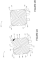
- FIG. 2B illustrates a top view of another solar cell assembly 220, according to an example implementation.
- the solar cell assembly 220 depicts an alternative configuration of the flexible circuit in which the first flexible tab 222 is disposed at a cropped flexible corner of a plurality of cropped flexible corners 228, which extend past a plurality of cropped cell corners 226.
- a bypass diode can be placed at a flexible corner rather than within the flexible circuit. This may further ease assembly of the solar cell assembly or a system of solar cell assemblies.
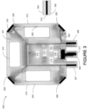
- FIG. 3 illustrates a flexible circuit 300, according to an example implementation.
- the flexible circuit 300 includes a flexible insulator 301, such as a Polyimide material. Other types of flexible insulators are possible.
- the flexible insulator 301 includes a bottom layer 302 and a top layer 303 and aspects of an electric circuit can be disposed between the bottom layer 302 and the top layer 303.
- the flexible insulator 301 includes a plurality of edges 304, a plurality of flexible corners 305, a first flexible tab 306, a second flexible tab 307, and a third flexible tab 308.
- the flexible insulator 301 further includes a plurality of openings 310 that are configured to interface with one or more flexible tabs of an adjacent flexible circuit, and a partial opening 312.
- the partial opening 312 includes a portion of the bottom layer 302 and does not include the top layer 303.
- the bottom layer 302 may correspond to a bottom of a solar cell assembly and the top layer 303 may be attached to a non-solar-facing surface of a solar cell.
- the partial opening 312 may insulate an electric component on one side, but allow the electric component to contact a solar cell.
- a bypass diode 318 is partially embedded in the flexible insulator 301, and may contact a non-solar-facing surface of the solar cell.
- the flexible insulator 301 is configured such that the edges 304 are configured to align with a solar cell such that the flexible insulator 301 is coextensive with the solar cell. This allows a solar assembly including the solar cell and the flexible circuit 300 to interface efficiently with other solar cell assemblies in a system of solar cells.
- the flexible insulator includes an opening 309 that exposes a portion of a non-solar-facing surface of a solar cell that is attached to the flexible circuit 300.
- the opening 309 is a first opening of the plurality of openings 310.
- the opening 309 is configured to accept an adjacent flexible tab of an adjacent flexible circuit, thereby allowing the adjacent flexible circuit to connect to the solar cell attached to the flexible circuit 300. In this manner, the opening 309 reduces the need for non-solar-facing welding for a system of solar cells.
- each opening of the plurality of openings 310 corresponds to a different edge of the flexible insulator 301.
- the solar cell assembly can be assembled into solar strings (e.g., a plurality of series-connected solar cells) that are oriented in a non-linear manner.
- the flexible circuit 300 further includes a circuit 314 that is substantially embedded in the flexible insulator 301.
- the circuit 314 includes a one or more metal traces 315, a plurality of electric contacts that are exposed on at least one side, and the bypass diode 318.
- the flexible circuit 314 is substantially embedded in the flexible insulator 301 because the metal traces 315 are surrounded by the flexible insulator 315, but the electric contacts and the bypass diode 318 are exposed.
- the plurality of contacts in Figure 3 include a first electric contact 316 exposed at a solar facing side of a flexible corner and a second electric contact 317 exposed at a solar-facing side of a flexible tab.
- the flexible circuit 300 includes a plurality of tabs, including the first flexible tab 306, and the first flexible tab 306 is associated with a bypass diode 318 of the circuit 314. Further, the second flexible tab 307 of the plurality of tabs is configured to provide a current path between the solar cell and an adjacent solar cell.
- each of the plurality of tabs extends from a same edge of the flexible insulator 301. This allows each tab to connect with the same adjacent solar cell, and further allows more edges available for the plurality of openings 310.
- the bypass diode 318 for a solar cell (e.g., the solar cell 106) is partially embedded in the partial opening 312.
- the top layer 303 includes an opening, and the bypass diode 318 is configured to contact a non-solar-facing surface of the solar cell via the opening.
- the bottom layer 302 corresponds to a bottom of a solar cell assembly and the top layer 303 is attached to a non-solar-facing surface of a solar cell when manufacturing a solar cell assembly.
- the partial opening 312 insulates the bypass diode 318 on one side, but allows the bypass diode to contact the solar cell.
- the bypass diode 318 can be installed in the solar cell assembly simultaneously with other portions of the circuit 314.
- the first electric contact 316 is configured to connect to another component in a system of solar cells.
- the first electric contact 316 may be connected via an interconnect to one or more electric leads of an adjacent solar cell.
- the second electric contact 317 is connected to the bypass diode 318, and the bypass diode 318 is configured to contact a non-solar-facing surface of another solar cell (e.g., an adjacent solar cell) via the second electric contact 317.
- the first flexible tab 306 allows for a simple-to-install connection between a bypass diode embedded in a first solar cell assembly and a non-solar-facing surface of an adjacent solar cell assembly.
- the solar cell (e.g., the solar cell 106) includes an n-side associated with negative doping and a p-side associated with positive doping.
- the first electric contact 316 and associated metal traces may correspond to the n-side
- the second electric contact 317 may correspond to the p-side.
- electric contacts at the second flexible tab 307 and the third flexible tab 308 may correspond to the n-side.
- the flexible tabs are configured to contact a non-solar-facing side of an adjacent solar cell, while the flexible corners 305 are configured to contact other components on a solar-facing side of the flexible circuit 300.
- the example depicted in Figure 3 includes n-type electric contacts configured for solar-facing connections and non-solar-facing connections and p-type electric contacts configured only for non-solar-facing connections.
- circuitry for a solar cell assembly is included in the flexible circuit 300. This may simplify and expedite assembly, but also may allow for testing and troubleshooting of the circuitry on the flexible circuit 300 prior to assembly.
- FIG 4 illustrates a flexible circuit 400, according to another example implementation.
- the flexible circuit 400 includes a flexible insulator 402, such as a Polyimide material.
- the flexible insulator 402 includes a plurality of cropped flexible corners 404, a first flexible tab 406, a second flexible tab 407, and a third flexible tab 408.
- Figure 4 shows the flexible insulator 402 is rectangular (for example, square-shaped) with four cropped flexible corners. As described above, this allows the flexible circuit 400 to align with and to be coextensive with a similarly shaped solar cell.
- the flexible insulator 402 does not include a plurality of openings that are configured to interface with one or more flexible tabs of an adjacent flexible circuit. Rather, additional contacts are provided on a solar-facing side of the flexible circuit 400.
- the flexible circuit 400 further includes a circuit 409 that is substantially embedded in the flexible insulator 402.
- the circuit 409 includes a first electric contact 410 disposed at a first cropped flexible corner and a second electric contact disposed at the first flexible tab 406, a third electric contact 414 disposed at a second cropped flexible corner, a fourth electric contact 416 disposed at a third cropped flexible corner, a fifth electric contact 424 disposed at the third cropped flexible corner, and a sixth electric contact 428 disposed at the third flexible tab 408.
- Other electric contacts are unlabeled for purposes of simplicity.
- the circuit 409 further includes a first metal trace 420 providing a current path between the first electric contact 410 and the third electric contact 414. This current path further corresponds to the second flexible tab 407.
- the circuit 409 further includes bypass diode 418 embedded in the flexible insulator 401, and a second metal trace 422 providing a current path between the second electric contact 412 and the fourth electric contact 416 via the bypass diode 418.
- the circuit 409 further includes a third metal trace 426 providing a current path between the fifth electric contact 424 and the sixth electric contact 428.
- the flexible circuit 400 is configured to interface with a solar cell and at least one adjacent solar cell.
- a solar cell includes an n-side associated with negative doping and a p-side associated with positive doping.
- the first electric contact 410, the third electric contact 414, the fifth electric contact 424, and the sixth electric contact 428 may correspond to the n-side, and the second electric contact 412 and the fourth electric contact 416 may correspond to the p-side.
- the flexible tabs are configured to contact a non-solar-facing side of an adjacent solar cell, while the cropped flexible corners 404 are configured to contact other components on a solar-facing side of the flexible circuit 400.
- the example depicted in Figure 4 includes n-type electric contacts configured for both solar-facing connections (e.g., the first electric contact 410, the third electric contact 414, and the fifth electric contact 424) and non-solar-facing connections (e.g., the sixth electric contact 428) and p-type electric contacts configured for both solar facing connections (e.g., the fourth electric contact 416) and non-solar-facing connections (e.g., the second electric contact 412).
- n-type electric contacts configured for both solar-facing connections (e.g., the first electric contact 410, the third electric contact 414, and the fifth electric contact 424) and non-solar-facing connections (e.g., the sixth electric contact 428) and p-type electric contacts configured for both solar facing connections (e.g., the fourth electric contact 416) and non-solar-facing connections (e.g., the second electric contact 412).
- the fourth electric contact 416 and the fifth electric contact 424 are disposed at the same cropped flexible corner, and each corresponds to a different metal trace. Accordingly, within examples, a single flexible corner may include a plurality of electric contacts. This may allow the bypass diode 418 to be accessed in a more adaptive manner when manufacturing a system of solar cells.
- FIG. 5A illustrates a corner 500 of a solar cell assembly, according to an example implementation.
- the corner 500 includes a cell corner 502, a top layer 504 of a flexible circuit, an electric contact 506 of a flexible circuit, and a bottom layer 508 of the flexible circuit.
- One or more electric leads 510 are disposed on a solar-facing surface of the cell corner 502, and an interconnect 512 is provided that connects the electric contact 506 with the one or more electric leads 510.
- the interconnect 512 can be welded or ribbon bonded to the electric contact 506 and the one or more electric leads 510 or a terminal of the one or more electric leads, for example.
- the electric contact 506 may be a first electric contact of a plurality of electric contacts.
- the interconnect 512 can be a wire bonded between the one or more electric leads 510 on the solar-facing surface of the solar cell and the first electric contact.
- FIG. 5B illustrates another corner 520 of a solar cell assembly, according to another example implementation.
- the corner 520 includes a cell corner 522, a top layer 524 of a flexible circuit, an electric contact 526 of the flexible circuit, and a bottom layer 528 of the flexible circuit.
- the electric contact 526 may be a first electric contact of a plurality of electric contacts.
- the flexible circuit has a flexible corner that is configured to bend such that the first electric contact is configured to couple to one or more electric leads 530 on a solar-facing surface of the solar cell. In particular, the electric contact 526 bends towards the one or more electric leads 530.
- the flexible circuit can reduce the number of components in the system.
- the interconnect 512 shown in Figure 5A is not included in Figure 5B because the flexible corner is configured to bend toward the solar-facing surface of the solar cell.
- Connecting the electric contact 526 to the one or more electric leads may include soldering the electric contact 526.
- FIG. 6 illustrates a system 600 of solar cells, according to an example implementation.
- the system 600 includes a plurality of solar strings, including a first solar string 602, a second solar string 604, and a third solar string 606.
- the first solar string includes a first solar cell assembly 608, a second solar cell assembly 610, and a third solar cell assembly 612. Aspects of the solar cell assemblies are omitted for purposes of simplicity
- each solar cell assembly in the system 600 may be configured similarly to the solar cell assembly 100 illustrated in Figures 1A and 1B .
- each solar cell assembly includes a solar cell 106 having a solar-facing surface 108 and a non-solar-facing surface 109.
- the solar cell includes a cell corner.
- Each solar cell assembly further includes a flexible circuit 110 coupled to the non-solar-facing surface 109 of the solar cell 106, and the flexible circuit 110 is substantially coextensive with the solar cell 106.
- the flexible circuit 110 includes a flexible insulator including a plurality of edges 111 aligned with the solar cell 106, a flexible corner 112 extending past the cell corner, and a flexible tab extending from an edge of the plurality of edges 111.
- the flexible circuit 110 further includes a circuit substantially embedded in the flexible insulator, and the circuit includes a first electric contact exposed at a solar-facing side of the flexible corner, and a second electric contact exposed at a solar-facing side of the flexible tab.
- Figure 6 includes at least one pair of adjacent solar cell assemblies.
- the pair 609 includes a first solar cell assembly 608 that is electrically coupled to a second solar cell assembly 610 via a first electric contact 614 and a second electric contact 618.
- the first electric contact 614 can be connected to the second solar cell assembly 610 via an interconnect 616 that electrically couples the first electric contact to a corresponding contact on the adjacent solar cell
- the second electric contact 618 can be connected via a space 620 in a flexible insulator of the second solar cell assembly 610.
- the second solar cell assembly 610 is connected to the third solar cell assembly 612 to complete the first solar string 602.
- the second solar string 604 and the third solar string 606 are configured in a similar manner to the first solar string.
- each solar cell assembly could be connected to one another to form a single source of solar power. Accordingly, the system 600 can be adaptably and quickly assembled by an end user rather than requiring a specialized manufacturing facility.
- the example systems, solar cell assemblies, and flexible circuits described herein provide allow for quick, adaptive, and reliable assembly of a solar cell system, and may reduce manufacturing costs while also providing a way to assemble the solar cell system at a convenient location for an end user.
- having modular solar cell assemblies allows for simplified changes to the system in reconfiguration contexts.
- including substantially all of the electric circuit components of the solar cell system in flexible circuits embedded in the solar cell assemblies reduces the required number of parts of the system, and also allows for pre-assembly testing and troubleshooting. This may particularly impactful in space applications, where welding or soldering is impracticable.
- including a flexible circuit on a non-solar-facing side of the solar cell system reduces shadowing and allows for shorter electric leads thereby reducing resistive losses on the solar-facing side of the solar cell system.
- a solar cell assembly having a flexible circuit comprises: a solar cell having a solar-facing surface and a non-solar-facing surface, the solar cell comprising a cell corner; a flexible circuit coupled to the non-solar-facing surface of the solar cell, wherein the flexible circuit is substantially coextensive with the solar cell, the flexible circuit comprising: a flexible insulator comprising a plurality of edges aligned with the solar cell, a flexible corner extending past the cell corner, and a flexible tab extending from an edge of the plurality of edges; and a circuit substantially embedded in the flexible insulator, wherein the circuit comprises a first electric contact exposed at a solar-facing side of the flexible corner, and a second electric contact exposed at a solar-facing side of the flexible tab.
- the flexible insulator comprises an opening that exposes a portion of the non-solar-facing surface of the solar cell, wherein the opening is configured to accept an adjacent flexible tab of an adjacent solar cell assembly.
- the opening is a first opening of a plurality of openings, and wherein each opening corresponds to a different edge of the flexible insulator.
- the circuit may further comprises a bypass diode for the solar cell, wherein the flexible insulator comprises a bottom layer and a top layer, wherein the top layer is coupled to the non-solar-facing surface of the solar cell, wherein the top layer comprises an opening, and wherein the bypass diode contacts the non-solar-facing surface of the solar cell via the opening.
- the circuit may further comprises a bypass diode for the solar cell, wherein the first electric contact is connected to the bypass diode, and wherein the bypass diode contacts a non-solar-facing surface of another solar cell via the second electric contact.
- the flexible corner is configured to bend such that the first electric contact couples to one or more electric leads on the solar-facing surface of the solar cell.
- the solar cell assembly further comprises a wire bonded between one or more electric leads on the solar-facing surface of the solar cell and the first electric contact.
- the solar cell is square with four cropped cell corners, wherein the flexible circuit is square with four cropped flexible corners, and wherein the cropped flexible corners of the flexible circuit each extend past the cropped cell corners of the solar cell.
- the flexible tab is a first flexible tab of a plurality of tabs, wherein the first flexible tab is associated with a bypass diode of the circuit, wherein a second flexible tab of the plurality of tabs is configured to provide a current path between the solar cell and an adjacent solar cell, and wherein each of the plurality of tabs extends from a same edge of the flexible insulator.
- the flexible insulator comprises a Polyimide material.
- the solar-facing surface of the solar cell comprises a center portion, and wherein a plurality of electric leads extend from the center portion towards the first electric contact.
- a flexible circuit for a solar cell assembly which comprises: a flexible insulator comprising: a plurality of edges, wherein the plurality of edges are configured to align with a solar cell such that the flexible insulator is coextensive with the solar cell; a flexible corner, wherein the flexible corner is configured to extent past a cell corner of the solar cell; and a flexible tab extending from an edge of the plurality of edges; and a circuit substantially embedded in the flexible insulator, wherein the circuit comprises a first electric contact exposed at a solar-facing side of the flexible corner, and a second electric contact exposed at a solar-facing side of the flexible tab.
- the flexible insulator comprises an opening that exposes a portion of a non-solar-facing surface of the solar cell, wherein the opening is configured to accept an adjacent flexible tab of an adjacent flexible circuit.
- the opening is a first opening of a plurality of openings, and wherein each opening corresponds to a different edge of the flexible insulator.
- the circuit further comprises a bypass diode for the solar cell, wherein the flexible insulator comprises a bottom layer and a top layer, wherein the top layer is configured to couple to a non-solar-facing surface of the solar cell, wherein the top layer comprises an opening, and wherein the bypass diode is configured to contact a non-solar-facing surface of the solar cell via the opening.
- the flexible insulator comprises a bottom layer and a top layer
- the top layer is configured to couple to a non-solar-facing surface of the solar cell
- the top layer comprises an opening
- the bypass diode is configured to contact a non-solar-facing surface of the solar cell via the opening.
- the circuit further comprises a bypass diode for the solar cell, wherein the first electric contact is connected to the bypass diode, and wherein the bypass diode is configured to contact a non-solar-facing surface of another solar cell via the second electric contact.
- the flexible corner is configured to bend such that the first electric contact is configured to couple to one or more electric leads on a solar-facing surface of the solar cell.
- the flexible insulator is rectangular with four cropped flexible corners.
- the flexible tab is a first flexible tab of a plurality of tabs, wherein the first flexible tab is associated with a bypass diode of the circuit, wherein a second flexible tab of the plurality of tabs is configured to provide a current path between the solar cell and an adjacent solar cell, and wherein each of the plurality of tabs extends from a same edge of the flexible insulator.
- a system of solar cells having flexible circuits which comprises: a plurality of solar cell assemblies, each solar cell assembly comprising: a solar cell having a solar-facing surface and a non-solar-facing surface, the solar cell comprising a cell corner; a flexible circuit coupled to the non-solar-facing surface of the solar cell, wherein the flexible circuit is substantially coextensive with the solar cell, the flexible circuit comprising: a flexible insulator comprising a plurality of edges aligned with the solar cell, a flexible corner extending past the cell corner, and a flexible tab extending from an edge of the plurality of edges; and a circuit substantially embedded in the flexible insulator, wherein the circuit comprises a first electric contact exposed at a solar-facing side of the flexible corner, and a second electric contact exposed at a solar-facing side of the flexible tab, wherein the plurality of solar cells assemblies comprises at least one pair of adjacent solar cell assemblies comprising a first solar cell assembly electrically coupled to a second solar cell assembly via the first electric
- system(s), device(s), and method(s) disclosed herein include a variety of components, features, and functionalities. It should be understood that the various examples of the system(s), device(s), and method(s) disclosed herein may include any of the components, features, and functionalities of any of the other examples of the system(s), device(s), and method(s) disclosed herein in any combination or any sub-combination, and all of such possibilities are intended to be within the scope of the disclosure.
Landscapes
- Photovoltaic Devices (AREA)
- Life Sciences & Earth Sciences (AREA)
- Engineering & Computer Science (AREA)
- Sustainable Development (AREA)
- Sustainable Energy (AREA)
Claims (15)
- Solarzellenanordnung (100) mit einem flexiblen Schaltkreis aufweisend:eine Solarzelle (106) mit einer Solar-zugewandten Fläche (108) und einer Nicht-Solar-zugewandten Fläche (109), wobei die Solarzelle (106) eine Zellenecke (208) aufweist;einen flexiblen Schaltkreis (300), der an die Nicht-Solar-zugewandte Fläche (109) der Solarzelle (106) gekoppelt ist, wobei sich der flexible Schaltkreis (300) im Wesentlichen zusammen mit der Solarzelle (106) erstreckt, wobei der flexible Schaltkreis (300) aufweist:einen flexiblen Isolator (301), der eine Vielzahl von Rändern (304), die mit der Solarzelle (106) ausgerichtet sind, eine flexible Ecke (112), die sich über die Zellenecke (208) hinaus erstreckt, und einen flexiblen Vorsprung (222) aufweist, der sich von einem Rand der Vielzahl von Rändern (304) aus erstreckt; undeine Schaltung (314), die im Wesentlichen in den flexiblen Isolator (301) eingebettet ist, wobei die Schaltung (314) einen ersten elektrischen Kontakt (316), der auf einer Solar-zugewandten Seite der flexiblen Ecke (112) freiliegt, und einen zweiten elektrischen Kontakt (317) aufweist, der auf einer Solar-zugewandten Seite des flexiblen Vorsprungs (222) freiliegt.
- Solarzellenanordnung (100) nach Anspruch 1, wobei der flexible Isolator (301) eine Öffnung (309) aufweist, die einen Teil der Nicht-Solar-zugewandten Fläche (109) der Solarzelle (106) freilegt, wobei die Öffnung (309) zum Aufnehmen eines angrenzenden flexiblen Vorsprungs einer angrenzenden Solarzellenanordnung eingerichtet ist, wobei optional die Öffnung (309) eine erste Öffnung (309) einer Vielzahl von Öffnungen (310) ist, und wobei jede Öffnung (309) einem anderen Rand des flexiblen Isolators (301) entspricht.
- Solarzellenanordnung (100) nach Anspruch 1 oder 2, wobei die Schaltung (314) ferner eine Überbrückungsdiode (318) für die Solarzelle (106) aufweist, wobei der flexible Isolator (301) eine unterste Schicht und eine oberste Schicht aufweist, wobei die oberste Schicht an die Nicht-Solar-zugewandte Fläche (109) der Solarzelle (106) gekoppelt ist, wobei die oberste Schicht eine Öffnung aufweist, und wobei die Überbrückungsdiode (318) die Nicht-Solar-zugewandte Fläche (109) der Solarzelle (106) über die Öffnung berührt und/oder wobei die Schaltung (314) optional ferner eine Überbrückungsdiode (318) für die Solarzelle (106) aufweist, wobei der erste elektrische Kontakt (316) mit der Überbrückungsdiode verbunden ist, und wobei die Überbrückungsdiode (318) eine Nicht-Solar-zugewandte Fläche (109) einer anderen Solarzelle (106) über den zweiten elektrischen Kontakt (317) berührt.
- Solarzellenanordnung (100) nach einem der Ansprüche 1-3, wobei die flexible Ecke (112) zum Biegen eingerichtet ist, so dass der erste elektrische Kontakt (316) an einen oder mehrere elektrische Leiter (510) auf der Solar-zugewandten Fläche (108) der Solarzelle (106) koppelt.
- Solarzellenanordnung (100) nach einem der Ansprüche 1-4, die ferner einen Draht aufweist, der zwischen einem oder mehreren elektrischen Leitern (510) auf der Solar-zugewandten Seite (108) der Solarzelle (106) und dem ersten elektrischen Kontakt (316) gebunden ist.
- Solarzellenanordnung (100) nach einem der Ansprüche 1-5, wobei die Solarzelle (106) rechteckig mit vier abgeschnittenen Zellenecken ist, wobei der flexible Schaltkreis (300) rechteckig mit vier abgeschnittenen flexiblen Ecken (128) ist, und wobei sich die abgeschnittenen flexiblen Ecken (128) des flexiblen Schaltkreises (300) über die abgeschnittenen Zellenecken der Solarzelle (106) hinaus erstrecken.
- Solarzellenanordnung (100) nach einem der Ansprüche 1-6, wobei der flexible Vorsprung (222) ein erster flexibler Vorsprung (222) einer Vielzahl von Vorsprüngen ist, wobei der erste flexible Vorsprung (222) mit einer Überbrückungsdiode (318) der Schaltung (314) verknüpft ist, wobei ein zweiter flexibler Vorsprung (114) der Vielzahl von Vorsprüngen eingerichtet ist, einen Strompfad zwischen der Solarzelle (106) und einer benachbarten Solarzelle (106) vorzusehen, und wobei sich jeder der Vorsprünge von dem gleichen Rand des flexiblen Isolators (301) aus erstreckt.
- Solarzellenanordnung (100) nach einem der Ansprüche 1-7, wobei der flexible Isolator (301) ein Polyimid-Material aufweist.
- Solarzellenanordnung (100) nach einem der Ansprüche 1-8, wobei die Solar-zugewandte Fläche (108) der Solarzelle (106) einen Mittelabschnitt (103) aufweist, und wobei sich eine Vielzahl von elektrischen Leitern (510) von dem Mittelabschnitt (103) in Richtung des ersten elektrischen Kontakts (316) erstreckt.
- Flexibler Schaltkreis (300) für eine Solarzellenanordnung (100) aufweisend:
einen flexiblen Isolator (301), der aufweist:eine Vielzahl von Rändern (304), wobei die Vielzahl von Rändern (304) zum Ausrichten mit einer Solarzelle (106) der Anordnung (100) ausgerichtet sind, so dass sich der flexible Isolator (301) zusammen mit der Solarzelle (106) erstreckt;eine flexible Ecke (112), wobei die flexible Ecke (112) eingerichtet ist, sich über eine Zellenecke (208) der Solarzelle (106) hinaus zu erstrecken; undein flexibler Vorsprung (222), der sich von einem Rand der Vielzahl von Rändern (304) aus erstreckt; undeine Schaltung (314), die im Wesentlichen in dem flexiblen Isolator (301) eingebettet ist, wobei die Schaltung (314) einen ersten elektrischen Kontakt (316), der auf einer Solar-zugewandten Seite der flexiblen Ecke (112) freigelegt ist, und einen zweiten elektrischen Kontakt (317) aufweist, der auf einer Solar-zugewandten Seite des flexiblen Vorsprungs (222) freigelegt ist. - Flexibler Schaltkreis (300) nach Anspruch 10, wobei der flexible Isolator (301) eine Öffnung (309) aufweist, die einen Teil einer Nicht-Solar-zugewandten Fläche (109) der Solarzelle (106) freilegt, wobei die Öffnung (309) eingerichtet ist, einen benachbarten flexiblen Vorsprung (222) eines benachbarten flexiblen Schaltkreises (314) aufzunehmen, wobei optional die Öffnung (309) eine erste Öffnung (309) einer Vielzahl von Öffnungen (310) ist, und wobei jede Öffnung (309) einem anderen Rand des flexiblen Isolators (301) entspricht, wobei optional der flexible Isolator (301) rechteckig mit vier abgeschnittenen flexiblen Ecken ist.
- Flexibler Schaltkreis (300) nach Anspruch 10 oder 11, wobei die Schaltung (314) ferner eine Überbrückungsdiode (318) für die Solarzelle (106) aufweist, wobei der flexible Isolator (301) eine unterste Schicht und eine oberste Schicht aufweist, wobei die oberste Schicht eingerichtet ist, an eine Nicht-Solar-zugewandte Fläche (109) der Solarzelle (106) zu koppeln, wobei die oberste Schicht eine Öffnung aufweist, und wobei die Überbrückungsdiode (318) eingerichtet ist, eine Nicht-Solar-zugewandte Fläche (109) der Solarzelle (106) über die Öffnung zu berühren und/oder wobei die Schaltung (314) optional ferner eine Überbrückungsdiode (318) für die Solarzelle (106) aufweist, wobei der erste elektrische Kontakt (316) mit der Überbrückungsdiode verbunden ist, und wobei die Überbrückungsdiode (318) eingerichtet ist, eine Nicht-Solar-zugewandte Fläche (109) einer anderen Solarzelle (106) über den zweiten elektrischen Kontakt (317) zu berühren.
- Flexibler Schaltkreis (300) nach einem der Ansprüche 10-12, wobei die flexible Ecke (112) eingerichtet ist, derart gebogen zu werden, dass der erste elektrische Kontakt (316) eingerichtet ist, an einen oder mehrere elektrische Leiter (510) auf der Solar-zugewandten Fläche (108) der Solarzelle (106) zu koppeln.
- Flexibler Schaltkreis (300) nach einem der Ansprüche 10-13, wobei der flexible Vorsprung (222) ein erster flexibler Vorsprung (222) einer Vielzahl von Vorsprüngen ist, wobei der erste flexible Vorsprung (222) mit einer Überbrückungsdiode (318) der Schaltung (314) verknüpft ist, wobei ein zweiter flexibler Vorsprung (114) der Vielzahl von Vorsprüngen eingerichtet ist, einen Strompfad zwischen der Solarzelle (106) und einer benachbarten Solarzelle (106) bereitzustellen, und wobei sich jeder der Vielzahl von Vorsprüngen von dem gleichen Rand des flexiblen Isolators (301) erstreckt.
- System (600) aus Solarzellen mit flexiblen Schaltkreisen aufweisend:
eine Vielzahl von Solarzellenanordnungen, wobei jede Solarzellenanordnung (100) aufweist:eine Solarzelle (106) mit einer Solar-zugewandten Fläche (108) und einer Nicht-Solar-zugewandten Fläche (109), wobei die Solarzelle (106) eine Zellenecke (208) aufweist;einen flexiblen Schaltkreis (300), der an die Nicht-Solar-zugewandte Fläche (109) der Solarzelle (106) gekoppelt ist, wobei sich der flexible Schaltkreis (300) im Wesentlichen zusammen mit der Solarzelle (106) erstreckt, wobei der flexible Schaltkreis (300) aufweist:einen flexiblen Isolator (301), der eine Vielzahl von Rändern (304), die mit der Solarzelle (106) ausgerichtet sind, eine flexible Ecke (112), die sich über die Zellenecke (208) hinaus erstreckt, und einen flexiblen Vorsprung (222) aufweist, der sich von einem Rand der Vielzahl von Rändern (304) aus erstreckt; undeine Schaltung (314), die im Wesentlichen in den flexiblen Isolator (301) eingebettet ist, wobei die Schaltung (314) einen ersten elektrischen Kontakt (316), der auf einer Solar-zugewandten Seite der flexiblen Ecke (112) freiliegt, und einen zweiten elektrischen Kontakt (317) aufweist, der auf einer Solar-zugewandten Seite des flexiblen Vorsprungs (222) freiliegt,wobei die Vielzahl von Solarzellenanordnungen zumindest ein Paar (609) aus benachbarten Solarzellenanordnung aufweist, die eine erste Solarzellenanordnung (608) aufweist, die elektrisch an eine zweite Solarzellenanordnung (610) über den ersten elektrischen Kontakt (316) und den zweiten elektrischen Kontakt (317) gekoppelt ist.
Priority Applications (1)
| Application Number | Priority Date | Filing Date | Title |
|---|---|---|---|
| EP23201110.6A EP4322714A3 (de) | 2020-08-21 | 2021-08-10 | Flexible schaltung für solarzellenanordnungen |
Applications Claiming Priority (2)
| Application Number | Priority Date | Filing Date | Title |
|---|---|---|---|
| US202063068840P | 2020-08-21 | 2020-08-21 | |
| US17/232,176 US11722094B2 (en) | 2020-08-21 | 2021-04-16 | Flexible circuit for solar cell assemblies |
Related Child Applications (1)
| Application Number | Title | Priority Date | Filing Date |
|---|---|---|---|
| EP23201110.6A Division EP4322714A3 (de) | 2020-08-21 | 2021-08-10 | Flexible schaltung für solarzellenanordnungen |
Publications (2)
| Publication Number | Publication Date |
|---|---|
| EP3958332A1 EP3958332A1 (de) | 2022-02-23 |
| EP3958332B1 true EP3958332B1 (de) | 2023-10-04 |
Family
ID=77274700
Family Applications (2)
| Application Number | Title | Priority Date | Filing Date |
|---|---|---|---|
| EP21190498.2A Active EP3958332B1 (de) | 2020-08-21 | 2021-08-10 | Flexible schaltung für solarzellenanordnungen |
| EP23201110.6A Pending EP4322714A3 (de) | 2020-08-21 | 2021-08-10 | Flexible schaltung für solarzellenanordnungen |
Family Applications After (1)
| Application Number | Title | Priority Date | Filing Date |
|---|---|---|---|
| EP23201110.6A Pending EP4322714A3 (de) | 2020-08-21 | 2021-08-10 | Flexible schaltung für solarzellenanordnungen |
Country Status (5)
| Country | Link |
|---|---|
| US (1) | US11722094B2 (de) |
| EP (2) | EP3958332B1 (de) |
| JP (1) | JP7757078B2 (de) |
| CA (1) | CA3127970A1 (de) |
| ES (1) | ES2968393T3 (de) |
Cited By (1)
| Publication number | Priority date | Publication date | Assignee | Title |
|---|---|---|---|---|
| EP4322714A3 (de) * | 2020-08-21 | 2024-05-29 | The Boeing Company | Flexible schaltung für solarzellenanordnungen |
Family Cites Families (20)
| Publication number | Priority date | Publication date | Assignee | Title |
|---|---|---|---|---|
| US4019924A (en) * | 1975-11-14 | 1977-04-26 | Mobil Tyco Solar Energy Corporation | Solar cell mounting and interconnecting assembly |
| US4227298A (en) * | 1978-09-05 | 1980-10-14 | Motorola, Inc. | Method for interconnecting photovoltaic devices |
| GB2040562B (en) * | 1979-01-13 | 1983-01-06 | Ferranti Ltd | Solar cell arrays |
| JPS56162658U (de) * | 1980-05-06 | 1981-12-03 | ||
| JP2567294Y2 (ja) * | 1992-02-15 | 1998-04-02 | シャープ株式会社 | 太陽電池モジュール |
| US5567248A (en) * | 1995-09-05 | 1996-10-22 | Chung; Darius | Modular solar cell contact arrangement |
| US6156967A (en) * | 1998-06-04 | 2000-12-05 | Tecstar Power Systems, Inc. | Modular glass covered solar cell array |
| JP2002231982A (ja) | 2001-01-30 | 2002-08-16 | Toppan Printing Co Ltd | フレキシブル太陽電池モジュールの形成方法 |
| US6531653B1 (en) * | 2001-09-11 | 2003-03-11 | The Boeing Company | Low cost high solar flux photovoltaic concentrator receiver |
| US9882330B2 (en) * | 2010-07-29 | 2018-01-30 | Andrew E. Kalman | Solar panel array |
| JP2013048166A (ja) | 2011-08-29 | 2013-03-07 | Sharp Corp | 太陽電池モジュール、太陽電池モジュールアレイ、および太陽電池モジュールの製造方法 |
| NL2011230C2 (en) * | 2013-07-26 | 2015-01-27 | Stichting Energie | Photo-voltaic cell its manufacture and an assembly of such photo-voltaic cells. |
| US10763383B2 (en) * | 2016-09-14 | 2020-09-01 | The Boeing Company | Nano-metal connections for a solar cell array |
| US20180076348A1 (en) | 2016-09-14 | 2018-03-15 | The Boeing Company | Rework and repair of components in a solar cell array |
| US20180358491A1 (en) | 2017-06-12 | 2018-12-13 | The Boeing Company | Solar cell array with bypassed solar cells |
| US12490523B2 (en) | 2017-06-12 | 2025-12-02 | The Boeing Company | Solar cell array with changeable string length |
| JP7040140B2 (ja) | 2018-03-07 | 2022-03-23 | セイコーエプソン株式会社 | 光電変換素子、光電変換モジュールおよび電子機器 |
| US12244265B2 (en) | 2018-03-28 | 2025-03-04 | The Boeing Company | Wiring for a rigid panel solar array |
| US11967923B2 (en) | 2018-03-28 | 2024-04-23 | The Boeing Company | Single sheet foldout solar array |
| US11722094B2 (en) * | 2020-08-21 | 2023-08-08 | The Boeing Company | Flexible circuit for solar cell assemblies |
-
2021
- 2021-04-16 US US17/232,176 patent/US11722094B2/en active Active
- 2021-08-10 ES ES21190498T patent/ES2968393T3/es active Active
- 2021-08-10 EP EP21190498.2A patent/EP3958332B1/de active Active
- 2021-08-10 EP EP23201110.6A patent/EP4322714A3/de active Pending
- 2021-08-11 CA CA3127970A patent/CA3127970A1/en active Pending
- 2021-08-20 JP JP2021134505A patent/JP7757078B2/ja active Active
Cited By (1)
| Publication number | Priority date | Publication date | Assignee | Title |
|---|---|---|---|---|
| EP4322714A3 (de) * | 2020-08-21 | 2024-05-29 | The Boeing Company | Flexible schaltung für solarzellenanordnungen |
Also Published As
| Publication number | Publication date |
|---|---|
| US11722094B2 (en) | 2023-08-08 |
| US20220060145A1 (en) | 2022-02-24 |
| EP4322714A3 (de) | 2024-05-29 |
| JP7757078B2 (ja) | 2025-10-21 |
| CA3127970A1 (en) | 2022-02-21 |
| EP3958332A1 (de) | 2022-02-23 |
| JP2022036064A (ja) | 2022-03-04 |
| ES2968393T3 (es) | 2024-05-09 |
| EP4322714A2 (de) | 2024-02-14 |
Similar Documents
| Publication | Publication Date | Title |
|---|---|---|
| KR102059612B1 (ko) | 전지모듈 내에서 공간을 적게 점유하는 상호 연결 부재 및 이를 포함하는 전지모듈 | |
| US11063322B2 (en) | Circuit body and battery module | |
| US4257821A (en) | Universal solar cell/conductor junction element and solar panel embodying same | |
| US11699820B2 (en) | Battery module with bimetallic terminal busbar and adaptable connector interface | |
| EP3387678B1 (de) | Verbindung für vielseitige flexible schaltung für flexible solarzellen | |
| US7833033B2 (en) | Solar panel junction box and components thereof | |
| CN101364679A (zh) | 电连接组件 | |
| US12095055B2 (en) | Sensing assembly, manufacturing method for thereof and battery module comprising the same | |
| CN116457990B (zh) | 配线模块 | |
| CN102544824A (zh) | 用于具有嵌入式电子部件的电子模块的互连构件 | |
| US11183724B2 (en) | Electrochemical cell connector having flexible circuit including plurality of arms with conductor in opening of arms and battery pack containing same | |
| EP3958332A1 (de) | Flexible schaltung für solarzellenanordnungen | |
| CN216354635U (zh) | 电池连接模组 | |
| CN116632462A (zh) | 电池连接模组 | |
| CN104428955B (zh) | 用于诸如功率部件的电气部件的互连的电路 | |
| JP7490351B2 (ja) | シャント抵抗モジュール及び、シャント抵抗モジュールの実装構造 | |
| CN216819794U (zh) | 全灌胶分体式光伏接线盒及光伏电池组件 | |
| CN223625245U (zh) | 端子及电子组装结构 | |
| CN222052108U (zh) | 一种软硬结合连接结构及其应用的pcb板 | |
| US20230369725A1 (en) | Busbar module | |
| CN118508003A (zh) | 电池保护板及电池 | |
| WO2018229822A1 (ja) | パワーモジュール | |
| EP4672878A1 (de) | Wechselrichter | |
| JPH0682906B2 (ja) | 多段型混成集積回路 |
Legal Events
| Date | Code | Title | Description |
|---|---|---|---|
| PUAI | Public reference made under article 153(3) epc to a published international application that has entered the european phase |
Free format text: ORIGINAL CODE: 0009012 |
|
| STAA | Information on the status of an ep patent application or granted ep patent |
Free format text: STATUS: THE APPLICATION HAS BEEN PUBLISHED |
|
| AK | Designated contracting states |
Kind code of ref document: A1 Designated state(s): AL AT BE BG CH CY CZ DE DK EE ES FI FR GB GR HR HU IE IS IT LI LT LU LV MC MK MT NL NO PL PT RO RS SE SI SK SM TR |
|
| STAA | Information on the status of an ep patent application or granted ep patent |
Free format text: STATUS: REQUEST FOR EXAMINATION WAS MADE |
|
| 17P | Request for examination filed |
Effective date: 20220721 |
|
| RBV | Designated contracting states (corrected) |
Designated state(s): AL AT BE BG CH CY CZ DE DK EE ES FI FR GB GR HR HU IE IS IT LI LT LU LV MC MK MT NL NO PL PT RO RS SE SI SK SM TR |
|
| RAP3 | Party data changed (applicant data changed or rights of an application transferred) |
Owner name: THE BOEING COMPANY |
|
| GRAP | Despatch of communication of intention to grant a patent |
Free format text: ORIGINAL CODE: EPIDOSNIGR1 |
|
| STAA | Information on the status of an ep patent application or granted ep patent |
Free format text: STATUS: GRANT OF PATENT IS INTENDED |
|
| INTG | Intention to grant announced |
Effective date: 20230330 |
|
| P01 | Opt-out of the competence of the unified patent court (upc) registered |
Effective date: 20230509 |
|
| GRAS | Grant fee paid |
Free format text: ORIGINAL CODE: EPIDOSNIGR3 |
|
| GRAA | (expected) grant |
Free format text: ORIGINAL CODE: 0009210 |
|
| STAA | Information on the status of an ep patent application or granted ep patent |
Free format text: STATUS: THE PATENT HAS BEEN GRANTED |
|
| AK | Designated contracting states |
Kind code of ref document: B1 Designated state(s): AL AT BE BG CH CY CZ DE DK EE ES FI FR GB GR HR HU IE IS IT LI LT LU LV MC MK MT NL NO PL PT RO RS SE SI SK SM TR |
|
| REG | Reference to a national code |
Ref country code: GB Ref legal event code: FG4D |
|
| REG | Reference to a national code |
Ref country code: CH Ref legal event code: EP |
|
| REG | Reference to a national code |
Ref country code: DE Ref legal event code: R096 Ref document number: 602021005583 Country of ref document: DE |
|
| REG | Reference to a national code |
Ref country code: IE Ref legal event code: FG4D |
|
| REG | Reference to a national code |
Ref country code: NL Ref legal event code: FP |
|
| REG | Reference to a national code |
Ref country code: LT Ref legal event code: MG9D |
|
| REG | Reference to a national code |
Ref country code: AT Ref legal event code: MK05 Ref document number: 1618661 Country of ref document: AT Kind code of ref document: T Effective date: 20231004 |
|
| PG25 | Lapsed in a contracting state [announced via postgrant information from national office to epo] |
Ref country code: GR Free format text: LAPSE BECAUSE OF FAILURE TO SUBMIT A TRANSLATION OF THE DESCRIPTION OR TO PAY THE FEE WITHIN THE PRESCRIBED TIME-LIMIT Effective date: 20240105 |
|
| PG25 | Lapsed in a contracting state [announced via postgrant information from national office to epo] |
Ref country code: IS Free format text: LAPSE BECAUSE OF FAILURE TO SUBMIT A TRANSLATION OF THE DESCRIPTION OR TO PAY THE FEE WITHIN THE PRESCRIBED TIME-LIMIT Effective date: 20240204 |
|
| PG25 | Lapsed in a contracting state [announced via postgrant information from national office to epo] |
Ref country code: LT Free format text: LAPSE BECAUSE OF FAILURE TO SUBMIT A TRANSLATION OF THE DESCRIPTION OR TO PAY THE FEE WITHIN THE PRESCRIBED TIME-LIMIT Effective date: 20231004 |
|
| PG25 | Lapsed in a contracting state [announced via postgrant information from national office to epo] |
Ref country code: AT Free format text: LAPSE BECAUSE OF FAILURE TO SUBMIT A TRANSLATION OF THE DESCRIPTION OR TO PAY THE FEE WITHIN THE PRESCRIBED TIME-LIMIT Effective date: 20231004 |
|
| PG25 | Lapsed in a contracting state [announced via postgrant information from national office to epo] |
Ref country code: LT Free format text: LAPSE BECAUSE OF FAILURE TO SUBMIT A TRANSLATION OF THE DESCRIPTION OR TO PAY THE FEE WITHIN THE PRESCRIBED TIME-LIMIT Effective date: 20231004 Ref country code: IS Free format text: LAPSE BECAUSE OF FAILURE TO SUBMIT A TRANSLATION OF THE DESCRIPTION OR TO PAY THE FEE WITHIN THE PRESCRIBED TIME-LIMIT Effective date: 20240204 Ref country code: GR Free format text: LAPSE BECAUSE OF FAILURE TO SUBMIT A TRANSLATION OF THE DESCRIPTION OR TO PAY THE FEE WITHIN THE PRESCRIBED TIME-LIMIT Effective date: 20240105 Ref country code: BG Free format text: LAPSE BECAUSE OF FAILURE TO SUBMIT A TRANSLATION OF THE DESCRIPTION OR TO PAY THE FEE WITHIN THE PRESCRIBED TIME-LIMIT Effective date: 20240104 Ref country code: AT Free format text: LAPSE BECAUSE OF FAILURE TO SUBMIT A TRANSLATION OF THE DESCRIPTION OR TO PAY THE FEE WITHIN THE PRESCRIBED TIME-LIMIT Effective date: 20231004 Ref country code: PT Free format text: LAPSE BECAUSE OF FAILURE TO SUBMIT A TRANSLATION OF THE DESCRIPTION OR TO PAY THE FEE WITHIN THE PRESCRIBED TIME-LIMIT Effective date: 20240205 |
|
| REG | Reference to a national code |
Ref country code: ES Ref legal event code: FG2A Ref document number: 2968393 Country of ref document: ES Kind code of ref document: T3 Effective date: 20240509 |
|
| PG25 | Lapsed in a contracting state [announced via postgrant information from national office to epo] |
Ref country code: SE Free format text: LAPSE BECAUSE OF FAILURE TO SUBMIT A TRANSLATION OF THE DESCRIPTION OR TO PAY THE FEE WITHIN THE PRESCRIBED TIME-LIMIT Effective date: 20231004 Ref country code: RS Free format text: LAPSE BECAUSE OF FAILURE TO SUBMIT A TRANSLATION OF THE DESCRIPTION OR TO PAY THE FEE WITHIN THE PRESCRIBED TIME-LIMIT Effective date: 20231004 Ref country code: PL Free format text: LAPSE BECAUSE OF FAILURE TO SUBMIT A TRANSLATION OF THE DESCRIPTION OR TO PAY THE FEE WITHIN THE PRESCRIBED TIME-LIMIT Effective date: 20231004 Ref country code: NO Free format text: LAPSE BECAUSE OF FAILURE TO SUBMIT A TRANSLATION OF THE DESCRIPTION OR TO PAY THE FEE WITHIN THE PRESCRIBED TIME-LIMIT Effective date: 20240104 Ref country code: LV Free format text: LAPSE BECAUSE OF FAILURE TO SUBMIT A TRANSLATION OF THE DESCRIPTION OR TO PAY THE FEE WITHIN THE PRESCRIBED TIME-LIMIT Effective date: 20231004 Ref country code: HR Free format text: LAPSE BECAUSE OF FAILURE TO SUBMIT A TRANSLATION OF THE DESCRIPTION OR TO PAY THE FEE WITHIN THE PRESCRIBED TIME-LIMIT Effective date: 20231004 |
|
| REG | Reference to a national code |
Ref country code: DE Ref legal event code: R097 Ref document number: 602021005583 Country of ref document: DE |
|
| PG25 | Lapsed in a contracting state [announced via postgrant information from national office to epo] |
Ref country code: DK Free format text: LAPSE BECAUSE OF FAILURE TO SUBMIT A TRANSLATION OF THE DESCRIPTION OR TO PAY THE FEE WITHIN THE PRESCRIBED TIME-LIMIT Effective date: 20231004 |
|
| PG25 | Lapsed in a contracting state [announced via postgrant information from national office to epo] |
Ref country code: CZ Free format text: LAPSE BECAUSE OF FAILURE TO SUBMIT A TRANSLATION OF THE DESCRIPTION OR TO PAY THE FEE WITHIN THE PRESCRIBED TIME-LIMIT Effective date: 20231004 |
|
| PG25 | Lapsed in a contracting state [announced via postgrant information from national office to epo] |
Ref country code: SK Free format text: LAPSE BECAUSE OF FAILURE TO SUBMIT A TRANSLATION OF THE DESCRIPTION OR TO PAY THE FEE WITHIN THE PRESCRIBED TIME-LIMIT Effective date: 20231004 |
|
| PG25 | Lapsed in a contracting state [announced via postgrant information from national office to epo] |
Ref country code: SM Free format text: LAPSE BECAUSE OF FAILURE TO SUBMIT A TRANSLATION OF THE DESCRIPTION OR TO PAY THE FEE WITHIN THE PRESCRIBED TIME-LIMIT Effective date: 20231004 Ref country code: SK Free format text: LAPSE BECAUSE OF FAILURE TO SUBMIT A TRANSLATION OF THE DESCRIPTION OR TO PAY THE FEE WITHIN THE PRESCRIBED TIME-LIMIT Effective date: 20231004 Ref country code: RO Free format text: LAPSE BECAUSE OF FAILURE TO SUBMIT A TRANSLATION OF THE DESCRIPTION OR TO PAY THE FEE WITHIN THE PRESCRIBED TIME-LIMIT Effective date: 20231004 Ref country code: EE Free format text: LAPSE BECAUSE OF FAILURE TO SUBMIT A TRANSLATION OF THE DESCRIPTION OR TO PAY THE FEE WITHIN THE PRESCRIBED TIME-LIMIT Effective date: 20231004 Ref country code: DK Free format text: LAPSE BECAUSE OF FAILURE TO SUBMIT A TRANSLATION OF THE DESCRIPTION OR TO PAY THE FEE WITHIN THE PRESCRIBED TIME-LIMIT Effective date: 20231004 Ref country code: CZ Free format text: LAPSE BECAUSE OF FAILURE TO SUBMIT A TRANSLATION OF THE DESCRIPTION OR TO PAY THE FEE WITHIN THE PRESCRIBED TIME-LIMIT Effective date: 20231004 |
|
| PLBE | No opposition filed within time limit |
Free format text: ORIGINAL CODE: 0009261 |
|
| STAA | Information on the status of an ep patent application or granted ep patent |
Free format text: STATUS: NO OPPOSITION FILED WITHIN TIME LIMIT |
|
| 26N | No opposition filed |
Effective date: 20240705 |
|
| PG25 | Lapsed in a contracting state [announced via postgrant information from national office to epo] |
Ref country code: SI Free format text: LAPSE BECAUSE OF FAILURE TO SUBMIT A TRANSLATION OF THE DESCRIPTION OR TO PAY THE FEE WITHIN THE PRESCRIBED TIME-LIMIT Effective date: 20231004 |
|
| PG25 | Lapsed in a contracting state [announced via postgrant information from national office to epo] |
Ref country code: SI Free format text: LAPSE BECAUSE OF FAILURE TO SUBMIT A TRANSLATION OF THE DESCRIPTION OR TO PAY THE FEE WITHIN THE PRESCRIBED TIME-LIMIT Effective date: 20231004 |
|
| REG | Reference to a national code |
Ref country code: DE Ref legal event code: R079 Ref document number: 602021005583 Country of ref document: DE Free format text: PREVIOUS MAIN CLASS: H01L0031050000 Ipc: H10F0019900000 |
|
| REG | Reference to a national code |
Ref country code: CH Ref legal event code: PL |
|
| PG25 | Lapsed in a contracting state [announced via postgrant information from national office to epo] |
Ref country code: LU Free format text: LAPSE BECAUSE OF NON-PAYMENT OF DUE FEES Effective date: 20240810 |
|
| PG25 | Lapsed in a contracting state [announced via postgrant information from national office to epo] |
Ref country code: CH Free format text: LAPSE BECAUSE OF NON-PAYMENT OF DUE FEES Effective date: 20240831 Ref country code: MC Free format text: LAPSE BECAUSE OF FAILURE TO SUBMIT A TRANSLATION OF THE DESCRIPTION OR TO PAY THE FEE WITHIN THE PRESCRIBED TIME-LIMIT Effective date: 20231004 |
|
| PG25 | Lapsed in a contracting state [announced via postgrant information from national office to epo] |
Ref country code: IE Free format text: LAPSE BECAUSE OF NON-PAYMENT OF DUE FEES Effective date: 20240810 |
|
| PGFP | Annual fee paid to national office [announced via postgrant information from national office to epo] |
Ref country code: NL Payment date: 20250826 Year of fee payment: 5 |
|
| PG25 | Lapsed in a contracting state [announced via postgrant information from national office to epo] |
Ref country code: FI Free format text: LAPSE BECAUSE OF FAILURE TO SUBMIT A TRANSLATION OF THE DESCRIPTION OR TO PAY THE FEE WITHIN THE PRESCRIBED TIME-LIMIT Effective date: 20231004 |
|
| PGFP | Annual fee paid to national office [announced via postgrant information from national office to epo] |
Ref country code: ES Payment date: 20250901 Year of fee payment: 5 |
|
| PGFP | Annual fee paid to national office [announced via postgrant information from national office to epo] |
Ref country code: DE Payment date: 20250827 Year of fee payment: 5 |
|
| PGFP | Annual fee paid to national office [announced via postgrant information from national office to epo] |
Ref country code: IT Payment date: 20250820 Year of fee payment: 5 |
|
| PGFP | Annual fee paid to national office [announced via postgrant information from national office to epo] |
Ref country code: BE Payment date: 20250827 Year of fee payment: 5 Ref country code: GB Payment date: 20250827 Year of fee payment: 5 |
|
| PGFP | Annual fee paid to national office [announced via postgrant information from national office to epo] |
Ref country code: FR Payment date: 20250825 Year of fee payment: 5 |
|
| PG25 | Lapsed in a contracting state [announced via postgrant information from national office to epo] |
Ref country code: CY Free format text: LAPSE BECAUSE OF FAILURE TO SUBMIT A TRANSLATION OF THE DESCRIPTION OR TO PAY THE FEE WITHIN THE PRESCRIBED TIME-LIMIT; INVALID AB INITIO Effective date: 20210810 |
|
| PG25 | Lapsed in a contracting state [announced via postgrant information from national office to epo] |
Ref country code: HU Free format text: LAPSE BECAUSE OF FAILURE TO SUBMIT A TRANSLATION OF THE DESCRIPTION OR TO PAY THE FEE WITHIN THE PRESCRIBED TIME-LIMIT; INVALID AB INITIO Effective date: 20210810 |