EP3958728B1 - Verfahren zur optischen inkohärenztomografie in der ophthalmologie - Google Patents
Verfahren zur optischen inkohärenztomografie in der ophthalmologie Download PDFInfo
- Publication number
- EP3958728B1 EP3958728B1 EP20719643.7A EP20719643A EP3958728B1 EP 3958728 B1 EP3958728 B1 EP 3958728B1 EP 20719643 A EP20719643 A EP 20719643A EP 3958728 B1 EP3958728 B1 EP 3958728B1
- Authority
- EP
- European Patent Office
- Prior art keywords
- image
- images
- branch
- imager
- representative
- Prior art date
- Legal status (The legal status is an assumption and is not a legal conclusion. Google has not performed a legal analysis and makes no representation as to the accuracy of the status listed.)
- Active
Links
Images


Classifications
-
- A—HUMAN NECESSITIES
- A61—MEDICAL OR VETERINARY SCIENCE; HYGIENE
- A61B—DIAGNOSIS; SURGERY; IDENTIFICATION
- A61B3/00—Apparatus for testing the eyes; Instruments for examining the eyes
- A61B3/10—Objective types, i.e. instruments for examining the eyes independent of the patients' perceptions or reactions
- A61B3/12—Objective types, i.e. instruments for examining the eyes independent of the patients' perceptions or reactions for looking at the eye fundus, e.g. ophthalmoscopes
-
- A—HUMAN NECESSITIES
- A61—MEDICAL OR VETERINARY SCIENCE; HYGIENE
- A61B—DIAGNOSIS; SURGERY; IDENTIFICATION
- A61B3/00—Apparatus for testing the eyes; Instruments for examining the eyes
- A61B3/10—Objective types, i.e. instruments for examining the eyes independent of the patients' perceptions or reactions
- A61B3/1025—Objective types, i.e. instruments for examining the eyes independent of the patients' perceptions or reactions for confocal scanning
-
- G—PHYSICS
- G06—COMPUTING OR CALCULATING; COUNTING
- G06T—IMAGE DATA PROCESSING OR GENERATION, IN GENERAL
- G06T2207/00—Indexing scheme for image analysis or image enhancement
- G06T2207/30—Subject of image; Context of image processing
- G06T2207/30004—Biomedical image processing
- G06T2207/30041—Eye; Retina; Ophthalmic
Definitions
- the present invention belongs to the field of ophthalmology. More specifically, the invention relates to an optical incoherence tomography method allowing real-time in vivo imaging of the retina, an ophthalmic imaging system, and a laser photocoagulation system of a retina.
- Macular edema is a fairly common retinal condition characterized by edema of the central region of the retina (macula) related to abnormalities of the small blood vessels, leading to a decrease in visual acuity.
- Macular edema is the main manifestation of diabetic retinopathy, which is the leading cause of blindness before the age of 55.
- the standard treatment for these macular edemas consists of photocoagulation of these vessels in the central area of the retina using a laser.
- Other diseases can also benefit from photocoagulation of the macula, such as retinal vein occlusions.
- the surgeon operating the laser only had a two-dimensional visualization of the retina at the slit lamp, seen from the front, on which the surgeon relies to locate the laser impact point on the surface of the retina, and to dose the laser power: it is recommended to apply the laser until a slight whitening is observed at the slit lamp. It therefore appears that in current surgical procedures, the focusing and dosage of the laser are very empirical. In fact, standard treatment procedures are not very reproducible from one practitioner to another.
- the eye is more or less stabilized with a contact lens held on the eye, which only very partially filters the continuous involuntary fixation movements of the eye.
- the laser impact may not correspond to the position targeted on the fundus image obtained by the slit lamp.
- the large laser impact size is achieved by delivering a wide laser beam, with a lateral diameter of the focal spot on the retina ranging from 100 ⁇ m to 500 ⁇ m, and having a small optical aperture, with a longitudinal extension (in depth) of the focal spot on the retina of approximately 300 ⁇ m.
- a large laser impact also makes it possible to overcome various ocular aberrations that reduce the accuracy of the laser impact localization.
- a real human eye is not strictly stigmatic, i.e. the image of a point is not a rigorously sharp point.
- These ocular aberrations can be static, the most common examples being vision defects corrected by glasses (myopia, hyperopia, astigmatism, etc.).
- Aberrations can also be dynamic, for example caused by micro-accommodations of the lens, the flow of the tear film, and eye movements. These aberrations result in a point spread function (PSF) that deviates from that of a theoretical perfect eye, and which varies rapidly over time.
- PSF point spread function
- the large size of current laser impacts is not adapted to the size of the areas to be treated.
- macroaneurysms typically have sizes varying between 100 ⁇ m and 300 ⁇ m, even though the laser impact has a diameter of approximately 300 ⁇ m, not counting the thermal diffusion occurring around the laser impact zone.
- lesions appear in the healthy tissues surrounding the area to be treated.
- the retinal blood vessel layer and the retinal pigment epithelium are surrounded by functional tissues, the alteration of which can lead to permanent vision loss.
- the SLO can benefit from optical sectioning by placing a screen with a small hole in it at the focal plane of the imager, an approach referred to as confocal.
- the holed screen physically rejects photons from out-of-focus planes.
- Each type of ophthalmoscope can be used in two detection configurations depending on the properties of the light used: incoherence or coherence.
- Coherence detection is mainly done using the optical coherence tomography technique, or OCT.
- This technique consists of producing interference between the light reflected by the retina and part of the illumination light used as a reference. Thanks to the interference patterns generated, the difference in propagation time between the retina and the reference beam can be determined, allowing an axial resolution of a few micrometers.
- ocular disturbances such as eye movements or optical aberrations affect the quality of the retinal image. While the effects of eye movements (blurring and distortions) can be minimized by post-processing, ocular aberrations are avoided by using a system with a small optical aperture, typically between 1 mm and 2 mm. Except for the axial resolution which does not depend on the optical aperture, this small optical aperture limits the resolution in other directions, and some retinal features are not imaged properly.
- an OCT system is weakly sensitive to defocus (corresponding to a change in accommodation of the eye), and is strongly sensitive to axial movements of the retina (pulsation) and the eye. Since the axial positioning of a therapeutic laser is given by a pure defocus, OCT is unsuitable for use in determining and controlling the defocus to be applied to the therapeutic laser in order to properly axially position the laser impact on the therapeutic target and thus avoid damaging healthy retinal tissues adjacent to the desired laser impact zone.
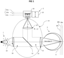
- the ophthalmic imaging system comprises a light source 1 adapted to emit an illumination light beam and an imager 2 configured to acquire an image of a light beam returned by a part to be imaged of an eye 3 illuminated by the illumination light beam. Between the light source 1, the imager 2 and the part to be imaged of the eye 3 there is an optical path in which the light beams propagate between the light source 1, the imager 2 and the part to be imaged of the eye 3.
- the optical system 14 can thus be broken down into a common part 15 extending to the interface 11 facing the eye 3, a first branch 16 connecting the light source 1 to the common part 15, and a second branch 17 connecting the imager 2 to the common part 15.
- a beam splitter S1 is arranged in the optical path to separate the first branch 16 and/or the second branch 17 relative to the common part 15 of the light path.
- a beam splitter allows part of an incident light ray to pass through while reflecting another part in another direction, and can be of any type, such as for example a semi-reflecting mirror.
- a single separator S1 is arranged, so that the light beam returned by the eye 3 traveling along the common part 15 of the optical path is deflected towards the second branch 17 intended for the imager 2. It is of course possible to provide more branches, and more separators S1, depending on the number of elements of the system which must use the optical path 14.
- the light source 1 is configured to illuminate the retina of the eye 3 so that the imager 2 can acquire an image of the retina of the eye 3.
- the light source 1 can emit in any wavelength capable of being used to highlight characteristics of the eye 3.
- the light source preferably emits light at one or more wavelengths only between 800 nm and 900 nm.
- the present method does not rely on the exploitation of light interference.
- the light source 1 therefore does not need to be coherent, and can be incoherent.
- the imager 2 comprises an optic and an image sensor 19 which can be of any type capable of imaging the retina of the eye 3, and for example be a CCD sensor.
- the imager 2 is capable of acquiring images at a frequency greater than 100 Hz, and preferably at a frequency greater than or equal to 150 Hz.
- the imager 2 can be configured to make full-field acquisitions, i.e. acquiring at each shot the entire transverse image envisaged for the image focal plane (for example of dimension 4° by 4° on the retinal surface).
- the imager 2 can be in a so-called confocal configuration, with a screen pierced with a hole in the focal plane of the imager.
- a scanner is used to transversely scan the position of the image of the confocal hole.
- this configuration allows for increased contrast and improved signal-to-noise ratio, it has the disadvantage of being more complex to implement. work, and above all to significantly reduce the acquisition speed, which can thus cause distortions between parts of images or between images due to eye movements.
- the optical properties of the optical path define an object focal plane 20 in the eye 3 and an image focal plane 21 at the imager 2, the image focal plane 21 being the conjugate plane of the object focal plane 20.
- the object focal plane 20 designates the area of the eye 3 from which the photons will be focused at the image focal plane 21 of the imager 2, and will consequently produce a sharp image.
- the positions of the object focal plane 20 and the image focal plane 21 depend on the optical characteristics of the optical path, i.e. the optical characteristics of its various components, as well as their spatial arrangement.
- the optical characteristics of the part of the eye 3 crossed by the light beams are not known in detail, and are variable over time. Indeed, in addition to eye movements, an eye 3 permanently exhibits micro-accommodations of the lens by modification of its vergence, and various other dynamic variations, which prevents knowing a priori the exact position of the image focal plane.
- the human retina is a complex volume composed of hypo-reflective and hyper-reflective layers.
- a lateral movement of the eye 3 can thus induce a displacement of the image focal plane, in particular to the extent that three particularly reflective elements are arranged in different layers of the retina: the photoreceptors, the blood vessels and the nerve fibers.
- optical characteristics of the part of the eye 3 crossed by the light beams cannot be controlled, it is possible on the other hand to modify the optical characteristics of the optical system 14 in order to move the object focal plane 20 along the object axis Z. More precisely, a modification of the second branch 17 of the optical system 14 makes it possible to move the image focal plane 21 and its conjugate the object focal plane 20.
- the second branch 17 of the optical system 14 is configured to be modified in order to move the object focal plane 20 along the object axis Z.
- the modification of the second branch 17 of the optical system 14 can be carried out by a modification of a distance L in this second branch 2 between the sensor 19 of the imager 2 and the output 12 which faces the imager, for example constituted by a lens or any other optical component.
- This modification of the distance L can in particular be obtained by a translation of the imager 2.
- the imager 2 can be movable in controlled translation in the direction of propagation of the light that the imager 2 receives from the optical system 14.
- the imager 2 can be mounted on a motorized plate which allows, depending on commands received, to move the imager 2 in translation using a motor 23. It is also possible for the modification of the second branch 17 of the optical system 14 to be carried out by a modification of an optical element present in this second branch 17. It is for example possible to vary the surface of a deformable mirror, or to modify the shape of a liquid lens, for example constituting the output 12 of the optical system 14.
- the patient's pupil Before implementing the method, it is preferable to dilate the patient's pupil and paralyze its accommodation. For example, it is possible to use a drop of tropicamide and a drop of 10% phenylphrine for this purpose.
- the width of the pupil obtained is preferably greater than 5 mm.
- a dilated pupil makes it possible to obtain a larger ocular numerical aperture, allowing the incident light to be better collimated and focused better on the retina.
- the lateral resolution (perpendicular to the direction of propagation of the beam, in x, y) of the incident light on the retina is proportional (for a perfect eye with circular aperture) to the inverse of the ocular numerical aperture, while the depth extension is proportional to the square of the inverse of the ocular numerical aperture.
- the high ocular numerical aperture limits the deformation (and in particular the broadening) of the illumination light beam at the focal spot on the retina, and therefore better confines the illumination.
- the imaging system is less impacted by the diffraction of the light beams.
- the paralysis of accommodation limits the effects of the dynamics of focusing (defocus) on the temporal evolution of the axial resolution.
- the method begins by illuminating the retina with an illuminating light beam emitted by the light source 1.
- the light source 1 emits the illuminating light beam which passes through the entrance 10, propagates through the first branch 16, passes through the separator S1, propagates through the common part 15 of the optical system 14, passes through the interface 11, and then reaches the eye 3.
- the illuminating light beam passes through the pupil, the vitreous body, and reaches the retina 6.
- the light encounters the different tissues constituting the retina 6, organized into retinal layers at different depths.
- the method therefore provides for the acquisition by the imager 2 of a series of images of an area to be imaged of the eye 3, the images corresponding to a plurality of different object focal planes 20 distributed along the object axis Z.
- the series of images comprises at least 20 images, and preferably at least 50 images, and more preferably at least 100 images.
- the illumination of the area to be imaged of the eye 3 by the illumination light beam may be maintained throughout the acquisition period, or may be intermittent and synchronized with each shot during the acquisition.
- the ophthalmic imaging system is modified so that the object focal plane 20 is moved along the object axis z.
- the acquisition comprises a modification of the second branch 17 of the optical system 14 between each acquired image, preferably without modification of the first branch 16 or of the common part 15.
- the modification of the second branch 17 of the optical system 14 between each acquired image may for example comprise a translation of the imager 2, and/or a modification of an optical element present in the second branch 17 of the optical system 14.
- the distribution of the object focal planes 20 extends in the area to be imaged of the eye 3 along the object axis Z over a distance greater than minus 50 ⁇ m, and preferably greater than 100 ⁇ m. It is even possible for this distance to be greater than 300 ⁇ m, in order to cover the entire typical thickness of the retina.
- two adjacent object focal planes corresponding to two successive images are less than 20 ⁇ m, and preferably less than 10 ⁇ m, and more preferably less than 5 ⁇ m along the object Z axis.
- the movement of the object focal plane 20 can be carried out continuously, for example by the continuous translation of the imager 2, and preferably at a constant speed. This allows increased speed and avoids possible jerks. However, it is then necessary to reduce the exposure time for each image in order to avoid the presence of movement-related artifacts, which induces a less favorable signal-to-noise ratio. It is also possible to operate the movement of the imager 2 step by step. This avoids the optical defects resulting from the movement of the imager 2 during the exposure, to the detriment however of the acquisition speed. It is also possible to increase the exposure time for each image in order to improve the signal-to-noise ratio.
- the translation speed of the object focal plane 20 is for example between 50 and 200 ⁇ m/s, such as for example 100 ⁇ m/s in the object axis Z.
- the imager 2 acquires images with a frequency between 50 Hz and 400 Hz, and preferably between 100 Hz and 300 Hz.
- the exposure time of the sensor 19 for each image is a compromise between a time that is long enough to obtain a satisfactory signal-to-noise ratio on the acquired image, but not too long so as not to be affected by motion blur resulting from movements of the eye 3 during the exposure time of the sensor 19.
- the exposure time of the sensor 19 is preferably less than 10 ms.
- the acquisition of the series of images is preferably carried out in less than 5 seconds, and more preferably in less than 3 seconds.
- the relationship between the displacement of the imager 2 and the corresponding displacement of the object focal plane in the area to be imaged of the eye 3 depends on the characteristics of the ophthalmic imaging system.
- the relationship can for example be a quadratic relationship.
- the optical magnification of the ophthalmic imaging system must also be taken into account. For example, with a magnification by a factor of 100, a displacement of the object focal plane of 1 ⁇ m along the object axis Z requires a displacement of 100 ⁇ m of the imager 2.
- a large magnification is therefore advantageous, since it is easier to control a displacement of 100 ⁇ m of the imager 2 than to control a displacement of 1 ⁇ m of the imager 2.
- Each acquired image is associated with a value representative of a variation parameter of the second branch 17 of the optical system 14 corresponding to the value taken by this parameter during the acquisition of said image.
- each image may correspond to a position of the imager 2 along the image axis at the time when this image is acquired. This position is then associated with said image, possibly in a transformed form.
- the system comprises a sensor configured to determine a value representative of a variation parameter of the second branch 17 of the optical system 14, the system being configured to synchronize the acquisition of an image with the measurement of the value of the variation parameter.
- a position sensor is controlled to acquire a measurement of the position of the stage supporting the imager 2 at each image acquisition.
- the imaging system is configured so that a first object focal plane 2a is located at the back of the retina 6 of the eye 3.
- the imager 2, whose sensor 19 is located at the image focal plane 21a acquires an image.
- the imager 2 is moved along the image axis to reduce the distance L between the sensor 19 and the output 12.
- the image focal plane 21b is therefore moved, as is its conjugate the object focal plane 20b.
- the object focal plane 20b is now located less deep in the retina 6.
- the imager 2 acquires another image. Then the imager 2 is moved along the image axis to further reduce the distance L between the sensor 19 and the output 12. The image focal plane 21c is therefore moved, as is its conjugate the object focal plane 20c. The object focal plane 20c is now located on the surface of the retina 6, and the imager 2 acquires an image. It should be noted that depending on the configuration of the ophthalmic imaging system, contrary to what is described above, a shortening of the distance L between the output 12 and the sensor 19 (and therefore a moving closer to the image focal plane 21) can cause the object focal plane 20 to move away along the object axis Z relative to the interface 11.
- the acquired images normally more numerous than the three of the simplified example above, form a series of acquired images, spatially ordered by the respective positions of the object focal plane 20 during their acquisitions.
- the order of the images of the image series corresponds to the order of the positions of the object focal plane 20 along of the object Z axis.
- the content of the images in the image series therefore reflects the three-dimensional structure of the imaged area of the eye 3.
- the modification of the second branch 17 consists of moving the imager 2 by a distance d between the acquisition of two images, and there is a ratio of 1 to 10 on the displacement of the object focal plane 21 on the object axis Z, the two successive images will represent imaged planes of the area to be imaged distant by d / 10, and their axial coordinates will be distant from d / 10.
- the exact positions of the object focal planes 20a, 20b, 20c along the object axis Z do not have to be known exactly before image acquisition. Indeed, since the different object focal planes 20a, 20b, 20c are distributed along the object axis Z, it is possible to determine the imaged depths a posteriori. Thus, the object focal plane 20b may correspond to the bottom of the retina 6, the object focal plane 20a being for example too deep.
- the pixel values of one image in the image series may then be modified by the pixel values of another image in the image series, in order to improve the signal-to-noise ratio, said image and said other image being successive images in the image series.
- the images may result from the sliding average of the images. It would be possible to keep the same number of acquired images, by modifying the values of each image with the images preceding or following it in the series. Preferably, however, successive images are combined with each other, so as to reduce the number of images in the image series.
- the image obtained may correspond to the average of the combined images, or more precisely the values of the pixels of the image obtained may result from the average of the values of the corresponding pixels of the combined images.
- This average may possibly be weighted, for example with a stronger weight for the central images of the set of combined images.
- each acquired image is associated with a value representative of a variation parameter of the second branch 17, it is easy to keep such a value associated with each combined image.
- the representative value of the variation parameter associated with a central image is kept for the combined image.
- the representative value of the variation parameter of the image resulting from the combination can also correspond to the average of the representative values of the variation parameter associated with each of the images which have been combined.
- Each of the acquired images result from the collection of photons during the exposure of the imager 2 at the time of the image capture.
- the light coming from the position of the object focal plane 20 at the time of image acquisition should reach the imager, generating a sharp image of the imaged area where the object focal plane 21 is located.
- the photons that are backscattered from the out-of-focus planes also reach the imager.
- FIG. 2 shows a view of layers of the retina 6, the vertical direction corresponding to the depth axis of the retina 6 and therefore to the object axis z.
- the first zone 51 delimited by white dashes corresponds to the imaged area included in the depth of field of the object focal plane 20.
- the second zone 52 is beyond the object focal plane 20, while the third zone 53 is below the object focal plane 20.
- the two white lines 54, 55 delimit the origins of the photons collected by the imager 2 in this configuration.
- the photons originating from the first zone 51 come from very close locations, and therefore form clear characteristics on the acquired image.
- This first zone 51 therefore produces low, medium and high spatial frequency components, which depend on the structure of the retina in this first zone 51.
- the photons originating from the second zone 52 and the third zone 53 are out of focus, and come from various locations in these zones. They cannot therefore form clear characteristics.
- the second zone 52 and the third zone 53 therefore produce only low and medium spatial frequency components. Only photons coming from the vicinity of the image focal plane can generate high spatial frequencies.
- Each acquired image corresponds to the superposition of several planes located at different depths along the object axis Z.
- At the level of the object focal plane 20 corresponds a first plane 51' formed by the photons coming from the first zone 51, on which the characteristics are clear.
- the image however includes other planes 52', 53' corresponding to the zones 52, 53 out of focus, for which the characteristics are blurred.
- the image reflects an area to be imaged wider than its depth of field, in a blurred manner however.
- the image then becomes restricted to the photons originating from the first zone 51 corresponding to the position of the object focal plane 20.
- optical sectioning designating the capacity of the imaging system to reject photons coming from out-of-focus planes.
- high-pass filtering is applied in spatial frequencies to each of the images in the image series to obtain a series of filtered images.
- the high-pass filtering aims to remove the low and medium spatial frequency components in the acquired images, i.e. to filter out the out-of-focus photons collected by the imager 2.
- the cut-off frequency of this high-pass filter is chosen to be greater than the average size of the structures of interest in the retina (blood vessels for example), which have a size of less than 50 ⁇ m. With a standardized Butterworth filter of order 2, this corresponds to a spatial cut-off frequency of between 0.04 and 0.1, and preferably between 0.06 and 0.09.
- a low-pass filter in spatial frequencies to remove very high spatial frequencies, typically higher than the spatial frequency of the photoreceptors of the sensor 19, which only appear as noise in the images.
- a cut-off frequency greater than 1 can be chosen for a normalized Butterworth filter of order 2, or even greater than 0.8 for a normalized Butterworth filter of order 2 if the signal-to-noise ratio is not satisfactory.
- the high-pass filter and the low-pass filter can be combined into a band-pass filter.
- the eye 3 When acquiring the series of images, it is possible for the eye 3 to move between two shots, generating between successive images a shift transverse to the object axis Z. It is therefore possible to implement a registration of the images, that is to say a translation and/or a rotation of one image relative to another.
- the registration parameters can be determined by means of a tracking of the movement of the area to be imaged (typically the retina), for example with a dedicated imager acquiring a video whose analysis would determine the movements to be compensated, and therefore the parameters. It is also possible to carry out a registration by means of an algorithm implementing a correlation between successive filtered images.
- the Figure 4a and the Figure 5a show examples of images acquired from a 900-frame image series.
- the Figure 4a shows image number 200 of the image series, and the Figure 5a shows image number 600.
- the images in the image series are combined 10 frames at a time, resulting in a series of 90 combined images replacing the 900 acquired images. More precisely, the pixel values of a combined image result from the average of 10 successive acquired images from the image series. Then a band-pass filtering is applied.
- FIG. 4b shows image 20 of the series of images corresponding to image number 200 illustrated by the Figure 4a
- the Figure 5b shows image number 60 of the series of 90 combined images corresponding to image 600 illustrated by the Figure 5b .
- the filtering removed the influences of the out-of-focus planes that caused blur.
- the acquired images represented a superposition of planes along the object Z axis
- the final images now only represent the imaged area of the eye at the object focal plane.
- the applied treatments therefore allow spatial discrimination along the object Z axis.
- the presence of retinal cells is now highlighted, whereas these cells were not visible in the acquired images such as those of Figures 4a And 5a .
- the filtering does not modify the association of each image with values representative of a variation parameter of the second branch 17, and therefore of the axial coordinates representative of the distribution of the object focal planes along the object axis Z.
- At least one value of a metric representative of the energy of a region of interest of each filtered image is determined.
- metrics can be used as a metric representative of the energy. For example, it is possible to determine a spatial frequency energy.
- Values of the metric representative of the energy of different filtered images thus determined are then combined to obtain a tomographic representation. If several metrics are used, this is a combination of metric values representative of the energy. As each filtered image is associated with values representative of a variation parameter of the second branch corresponding to axial coordinates representative of the distribution of the object focal planes along the axis, the values of the metric representative of the energy of these filtered images are also. Obtaining the tomographic representation therefore consists in spatially organizing these metric values according to their values representative of a variation parameter of the second branch 17 corresponding to axial coordinates. For example, if the variation parameter is a position of the imager 2, the metric values are organized according to the positions of the imager 2 at the time of acquisition of the acquired images.
- the tomographic representation can simply be the three-dimensional set formed by the juxtaposition along the object axis Z of the filtered images. It is preferable, however, to have a two-dimensional tomographic representation that can take into account in one or two dimensions the three-dimensional structure of the imaged area.
- the method may comprise a step in which an axial coordinate of a local maximum of the energy metric is determined from the tomographic representation, and therefore a value representative of a variation parameter, and the second branch 17 is then adjusted as a function of this value representative of the variation parameter so that the image focal plane 21 has a position corresponding to an axial coordinate of the local maximum of the energy metric, and at least one image is acquired.
- the imaging system was set up by moving the imager 2 so that the object focal plane 20 was at the coordinate 190 ⁇ m on the object Z axis, and ten images were acquired successively. These images were combined by calculating the average of the values of each pixel.
- the figure 7 shows the result of this acquisition. A sharp and precisely localized image of the retinal nerve fiber layer is directly obtained (the white graphic scale at the bottom left is 50 ⁇ m).
- the imaging system was configured by moving the imager 2 so that the object focal plane 20 was at the 30 ⁇ m coordinate on the object Z axis, and ten images were acquired successively. These images were combined by calculating the average of the values of each pixel.
- the figure 8 shows the result of this acquisition. We directly obtain a clear and precisely localized image of the photoreceptor layer (the white graphic scale at the bottom left is 50 ⁇ m).
- Tomographic imaging can thus be used to detect layers with a high spatial frequency content, in other words to determine the object focal planes for which sharp images with significant characteristics can be generated.
- This aspect is all the more interesting for imaging or treating patients with retinal diseases. While for a healthy subject, the reflective layers of the retina are easy to localize, this is not the case with a retinal disease, where the retinal anatomy can completely change.
- each image is associated with a value representative of a variation parameter of the second branch 17 of the corresponding optical system 14. to the value taken by this parameter during the acquisition of said image.
- These parameter values associated with the acquired images are preserved during the process, for example during the application of high-pass filtering, the determination of the metric representing the energy, or even during the combination of images with each other.
- the identification and localization of a characteristic element on the tomographic representation makes it possible to determine the axial coordinate of this element in the tomographic representation, and therefore to identify the representative value of a variation parameter corresponding to the image where this characteristic is located.
- This variation parameter thus determined can be used to control the imaging system or a laser to precisely target an area of the eye 3. In the case of using the imager 2, it is therefore sufficient to reproduce the variation of the second branch 17. In the case of using a laser, it is sufficient to apply a similar variation on the optical path of the laser beam. For example, if the variation parameter associated with the images is a position of the imager 2, it is sufficient to match it with a corresponding position of the laser, for example by means of a mathematical relationship linking a value of the variation parameter to a laser command.
- the tomographic representation can also be a B-type representation.
- Such a representation typically maps a representative energy metric value to each axial coordinate and to each coordinate in a direction perpendicular to the object Z axis.
- Such a type B representation may be constructed in particular by determining a metric value representative of the energy for each of a plurality of areas of interest of each filtered image.
- Each area of interest has a first dimension in a first direction X perpendicular to the object axis Z, and a second dimension in a second direction Y perpendicular to the object axis Z and to the first direction X.
- the first dimension is smaller than the second dimension, preferably by a factor of 10.
- the second dimension covers the majority of the dimension of the filtered image in the second direction Y, and preferably covers the entire dimension of the filtered image in the second direction Y, typically its entire height.
- the first dimension may be reduced to one pixel, or may extend over several pixels, preferably however over a number of pixels less than 10.
- the areas of interest of the filtered image may be distinct, but preferably overlap in the first direction X, for example with an offset between them in the first direction X less than their widths.
- FIG. 9 A simplified example is illustrated by the figure 9 , in which three successive filtered images 71, 72, 73 are represented in the direction of the object axis Z.
- Each filtered image 71, 72, 73 extends over a plane in the first direction X and the second direction Y, which form with the direction of the object axis Z an orthogonal reference frame.
- a first sub-zone 71a, 72a, 73a is defined, which extends over the entire height of the filtered image in the second direction Y, for example over 80 pixels, but over a small width in the first direction X, for example 4 pixels.
- a metric value representative of the energy is calculated for each first sub-zone 71a, 72a, 73a, for example the spatial frequency energy as in the illustrated case, or the spatial variance.
- the positions of sub-areas 71a, 72a, 73a on the different filtered images remain identical, corresponding to the same pixels.
- a second sub-area 71b, 72b, 73b of the same size as the first sub-area 71a, 72a, 73a is defined, offset on each filtered image 71, 72, 73 in the first X-direction relative to the first sub-area 71a, 72a, 73a.
- the second sub-area 71b, 72b, 73b is shown in FIG. figure 9 as not covering the first sub-area 71a, 72a, 73a.
- the second sub-area 71b, 72b, 73b is offset in the first X direction by a distance less than the width of the first sub-area 71a, 72a, 73a, and therefore covers the latter.
- the offset may be only one pixel between two sub-areas.
- a metric value representative of the energy is calculated for each second sub-area 71b, 72b, 73b. Then the same applies for third sub-areas 71c, 72c, 73c offset relative to the second sub-areas 71b, 72b, 73b.
- the tomographic representation according to the invention achieves a very satisfactory result, without requiring the implementation of complex interference measurements.
- the depth (along Z) in the retina of each layer is known, as well as the corresponding imaging system controls, as shown above.
- the size of the subareas influences the contrast and resolution of the tomographic representation.
- the larger the size of the subareas the less details will be preserved (such as longitudinal blood vessels and photoreceptors), and the layers will be smoother, as in the case of the OCT image of the figure 12 .
- the tomographic representation is noisier, but the finer details are preserved, allowing better visualization of structures such as blood vessels or photoreceptors.
- the system illustrated by the figure 1 is a simplified diagram of an exemplary imaging system according to a possible embodiment of the invention.
- the optical system 14 typically comprises numerous optical elements.
- the optical system 14 may comprise elements of an adaptive optics loop and elements for moving light beams.
- the imaging system may comprise a treatment laser.
- figure 13 thus presents a more detailed example of an imaging system, by way of non-limiting example, the different elements constituting it being able to be combined or taken in isolation in an imaging system.
- This second light source 1' is used to detect these alterations of the wave front.
- a real human eye 3 is not strictly stigmatic, that is to say that the image of a point is not a rigorously sharp point.
- the propagation of light in the eye 3 highlights ocular aberrations which give rise to defects in this light, and in particular with regard to its wavefront.
- These ocular aberrations can be static, the most common examples being vision defects corrected by glasses (myopia, hyperopia, astigmatism, etc.).
- Aberrations can also be dynamic, for example caused by micro-accommodations of the lens, the flow of the tear film, and eye movements. These aberrations result in a point spread function ("Point Spread Function" or PSF in English) which deviates from that of a theoretical perfect eye, and which varies rapidly over time.
- PSF Point Spread Function
- the second light source has wavelengths between 600 nm and 700 nm, in particular because this range highlights the main aberrations, and is preferably still monochromatic.
- a first actuator makes it possible to control the movement of the light beam in the optical path relative to the retina of the eye 3.
- the first actuator comprises a scanner SC1 formed by two pivoting mirrors, and makes it possible to scan the entire central zone of the retina.
- the light then passes through an interface 11 facing the eye 3 through which the illuminating light beam exits to reach the eye 3.
- the illuminating light beam passes through the pupil, the vitreous body, and reaches the retina 6.
- the light encounters the different tissues constituting the retina 6, organized into retinal layers at different depths.
- the light is backscattered by these tissues and exits the eye, constituting an image light beam originating from the eye which enters the optical system 14 via the interface 11.
- the image light beam passes back through the scanner SC1, then crosses the separator S1, and reaches a corrective element 30 of the adaptive optics, used to correct the wavefront of the light beams passing through the eye 3, both the image light beam and the laser beam, in order to compensate for the deformations undergone by the light fluxes in the eye 3.
- the corrective element 30 is a deformable mirror whose surface changes to compensate for the measured wavefront deformations.
- the image light flux then passes through a separator S3 which derives from the optical path an image of the retina to one or more imagers, upstream of the corrective element 30 of the adaptive optics. Another part of the image light flux continues towards a separator S4 which deflects the light flux towards a wave surface analyzer 31 or wave front analyzer, configured to receive light from the optical path.
- the light is derived by means of the separator S4 placed on the optical path.
- the wave surface analyzer 31 determines a measurement representative of a shape of a wave surface of the light passing along the optical path. More precisely, the wave surface analyzer 31 decomposes a wave front into elementary wave fronts and it makes it possible to determine for each elementary wave front its orientation. The measurement of these orientations makes it possible after integration to go back to the shape of the wave front.
- a feedback loop 32 makes it possible to use the measurements of the wave surface analyzer 31 to control the correction element 30. More precisely, the measurements of the wave surface analyzer 31 are received and processed by a processing module of the feedback loop 32, preferably a real-time computer, configured to receive the measurement of the wave surface analyzer, and to control the correction element 30 according to the measurement of the wave surface analyzer, in order to compensate for the detected disturbances.
- the processing module calculates the commands (for example voltages or intensities) to be sent to the deformable mirror, also placed in a pupil plane. The surface of the deformable mirror then changes to compensate for the measured wavefront deformations.
- the image light flux derived by the separator S3 to the imager 2 then passes into a separator S5 which makes it possible to derive a portion of the light flux traveling along the optical path toward the output 12 facing the imager 2, through which the image light beam exits to reach the imager 2, which makes it possible to obtain an image of the area of the retina of the eye 3 facing the interface 11.
- a secondary imager 2' may be provided, supplied with light flux from the separator S5 through a secondary output 12'.
- This secondary imager 2' is a stabilization camera used to implement a regulation to control the position of the interface 11 with respect to the retina to be treated.
- a stabilization loop 33 connects the secondary imager 2' to the first actuator. More specifically, the secondary imager 2' transmits acquired images to a processing module of the stabilization loop 33, preferably a real-time computer, which from these images determines a command of the scanner SC1 of the first actuator to move the light beam in the optical path relative to the retina of the eye 3 in order to stabilize the position of the light beam, in particular by compensating for involuntary movements of the eye 3.
- the processing module can for example use an image of the photoreceptors and a correlation-type algorithm to determine the movements of the retina, and determine a command of the first actuator so that the light beam follows these movements.
- the system may include a photocoagulation laser 35 configured to emit in an emission direction a laser beam into the optical system.
- the photocoagulation laser 35 may include a laser source and a transport optical fiber having a core diameter preferably less than 12 ⁇ m, and more preferably less than 8 ⁇ m.
- the laser source is preferably a fiber laser source, i.e. one the amplifying medium is created in an optical fiber doped with a rare earth, and can be single-mode.
- the photocoagulation laser 35 is configured to emit in a wavelength between 520 nm and 690 nm, preferably between 540 nm and 630 nm.
- the photocoagulation laser 35 may be associated with a control member 36 configured to determine the value of the variation parameter corresponding to the position of a target in the tomographic representation derived from the images acquired by the imager 2, and to control the photocoagulation laser 35 by means of a depth command (z) derived from this value of the variation parameter. More precisely, the photocoagulation laser 35 is movable in translation in its emission direction and the depth command is a command to move the photocoagulation laser 35.
- a motor 37 may be provided to move the photocoagulation laser 35 in translation in its emission direction. It is this motor which then receives the depth command (z) sent by the control member 36.
- the tomographic representation associates variation parameter values with each area of the imaged area (such as a position of the imager 2), it is possible to assign a variation parameter value to a laser target identified on the tomographic representation.
- the controller 36 can therefore determine the commands to be applied to the photocoagulation laser 35 so that the laser beam reaches this laser target precisely, without damaging adjacent tissue, for example by means of a relationship linking a value of the variation parameter to a laser control value, such as a laser movement or a laser position.
- the control member 36 is further configured to determine a movement command (x, y) of the laser beam at least in a plane perpendicular to the direction of propagation of the laser, defined by two distinct directions denoted x and y.
- the second actuator may comprise, as illustrated in the figure 13 , an SC2 scanner positioned in the optical path and adapted to move the laser beam in a focal plane (x, y) perpendicular to the propagation of the laser beam,
- the SC2 scanner acts for example by modifying the respective orientations of two mirrors facing each other, thus angularly shifting the laser beam which emerges from them.
- the control member 36 may be any computer, such as for example a real-time calculator, comprising a processor and a memory, capable of determining commands for the laser beam from information derived from the tomographic representation of the eye 3, possibly supplemented by other information, some of which may correspond to data entered by an operator, such as for example an instruction for the area to be treated.
- a real-time calculator comprising a processor and a memory, capable of determining commands for the laser beam from information derived from the tomographic representation of the eye 3, possibly supplemented by other information, some of which may correspond to data entered by an operator, such as for example an instruction for the area to be treated.
- the photocoagulation laser 35 After being positioned along its direction by the motor 37 controlled by the depth command (z) sent by the control member 36, the photocoagulation laser 35 emits a laser beam passing through the lens 38, then arrives at the scanner SC2 where it is reoriented in the x and y directions in accordance with the movement commands sent by the control member 36.
- the laser beam then joins the separator S4, then travels the same optical path (in the opposite direction) as the image light beam, namely it passes through the separator S3, the corrective element 30 of the adaptive optics, the separator S1, and the first actuator (scanner SC1) before passing through the interface 11 to reach the retina of the eye 3.
Landscapes
- Life Sciences & Earth Sciences (AREA)
- Health & Medical Sciences (AREA)
- Medical Informatics (AREA)
- Biophysics (AREA)
- Ophthalmology & Optometry (AREA)
- Engineering & Computer Science (AREA)
- Biomedical Technology (AREA)
- Heart & Thoracic Surgery (AREA)
- Physics & Mathematics (AREA)
- Molecular Biology (AREA)
- Surgery (AREA)
- Animal Behavior & Ethology (AREA)
- General Health & Medical Sciences (AREA)
- Public Health (AREA)
- Veterinary Medicine (AREA)
- Eye Examination Apparatus (AREA)
Claims (13)
- Ophthalmisches Bildgebungsverfahren eines abzubildenden Teils eines Auges mittels eines ophthalmischen Bildgebungssystems, wobei das ophthalmische Bildgebungssystem umfasst:- eine Lichtquelle (1), die geeignet ist, einen Beleuchtungslichtstrahl zu senden,- einen Bildgeber (2), der geeignet ist, ein Bild eines zurückgesendeten Lichtstrahls zu erfassen,- ein für die Ausbreitung von Lichtstrahlen geeignetes optisches System (14), wobei das optische System (14) einen gemeinsamen Teil (15) umfasst, der sich bis zu einer Schnittstelle (11) am Auge (3) erstreckt, wobei ein erster Arm (16) die Lichtquelle mit dem gemeinsamen Teil (15) verbindet und ein zweiter Arm (17) den Bildgeber (2) mit dem gemeinsamen Teil (15) verbindet, dadurch gekennzeichnet, dass das Verfahren die folgenden Schritte umfassta) Beleuchten des abzubildenden Teils des Auges durch einen von der Lichtquelle (1) gesendeten Beleuchtungslichtstrahl und Erfassen durch den Bildgeber (2) einer Reihe von Bildern des abzubildenden Bereichs, die einer Vielzahl unterschiedlicher Objektfokalebenen (20) entsprechen, die entlang einer Objektachse (Z) verteilt sind, wobei die Erfassung eine Änderung eines Variationsparameters des zweiten Arms (17) des optischen Systems (14) zwischen jedem erfassten Bild umfasst,b) Anwenden eines Hochpassfilters in räumlichen Frequenzen auf jedes der Bilder der Bildserie, um eine Serie gefilterter Bilder zu erhalten,c) Bestimmen, für jedes gefilterte Bild, mindestens eines Metrikwerts, der für die Energie eines interessierenden Bereichs jedes gefilterten Bildes repräsentativ ist, undd) Kombinieren von Werten einer Metrik, die für die Energie verschiedener gefilterter Bilder repräsentativ ist, die jeweils axialen Koordinaten zugeordnet sind, die für die Verteilung der Objektfokalebenen (20) entlang der Objektachse (Z) repräsentativ sind, um eine tomografische Darstellung zu erhalten.
- Verfahren nach Anspruch 1, wobei die Achskoordinaten repräsentativen Werten eines Variationsparameters des zweiten Arms (17) der erfassten Bilder entsprechen, die den gefilterten Bildern entsprechen.
- Verfahren nach einem der vorhergehenden Ansprüche, wobei die Änderung des zweiten Arms des optischen Systems zwischen jedem erfassten Bild eine Verschiebung des Bildgebers und/oder eine Änderung eines im zweiten Arm des optischen Systems vorhandenen optischen Elements umfasst.
- Verfahren nach einem der vorhergehenden Ansprüche, wobei die Bildserie der Netzhaut mindestens 20 Bilder umfasst, die ohne Änderung des ersten Arms und des gemeinsamen Teils des optischen Systems erfasst wurden.
- Verfahren nach einem der vorhergehenden Ansprüche, wobei die Erfassung der Bildserie in weniger als 5 Sekunden erfolgt.
- Verfahren nach einem der vorhergehenden Ansprüche, wobei die tomografische Darstellung eine Darstellung des Typs A ist, die eine Metrik, die für die Energie für eine Vielzahl von Axialkoordinaten repräsentativ ist, in Übereinstimmung bringt, oder die tomografische Darstellung eine Darstellung des Typs B ist, die eine Metrik, die für die Energie für eine Vielzahl von Axialkoordinaten und eine Vielzahl von Koordinaten in einer Richtung senkrecht zur Objektachse repräsentativ ist, in Übereinstimmung bringt.
- Verfahren nach einem der vorhergehenden Ansprüche, wobei aufeinanderfolgenden erfassten Bilder miteinander kombiniert werden, um ein kombiniertes Bild zu erhalten, dessen Pixelwerte einer Kombination der Pixelwerte der aufeinanderfolgenden erfassten Bilder entsprechen.
- Verfahren nach vorhergehendem Anspruch, wobei wenigstens drei aufeinanderfolgende erfasste Bilder miteinander kombiniert werden, und die Kombination der Pixelwerte der aufeinanderfolgenden erfassten Bilder aus einem Durchschnitt dieser Pixelwerte der aufeinanderfolgenden erfassten Bilder besteht.
- Verfahren nach einem der vorhergehenden Ansprüche, wobei die Metrik, die für die Energie repräsentativ ist, eine räumliche Frequenzenergie, eine räumliche Varianz des Bildes, eine laplazische Energie des Bildes oder eine Brennerfunktion des Bildes ist.
- Verfahren nach einem der vorhergehenden Ansprüche, das ferner einen Schritt e) umfasst, bei dem ein Wert, der für einen Variationsparameter des zweiten Arms (17) repräsentativ ist, der einem lokalen Maximum der Energiemetrik entspricht, aus der Darstellung bestimmt wird, und der zweite Arm (17) dann gemäß diesem repräsentativen Wert des Variationsparameters so eingestellt wird, dass die Bildfokusebene (21) eine Position hat, die einer axialen Koordinate des lokalen Maximums der Energiemetrik entspricht, und mindestens ein Bild erfasst wird.
- Ophthalmisches Bildgebungssystem, umfassend:- eine Lichtquelle (1), die geeignet ist, einen Beleuchtungslichtstrahl zu senden,- einen Bildgeber (2), der geeignet ist, ein Bild eines zurückgesendeten Lichtstrahls zu erfassen,- ein für die Ausbreitung von Lichtstrahlen geeignetes optisches System (14), wobei das optische System (14) einen gemeinsamen Teil (15) umfasst, der sich bis zu einer Schnittstelle (11) am Auge (3) erstreckt, wobei ein erster Arm (16) die Lichtquelle mit dem gemeinsamen Teil (15) verbindet und ein zweiter Arm (17) den Bildgeber (2) mit dem gemeinsamen Teil (15) verbindet, wobei das ophthalmische Bildgebungssystem ausgelegt ist, um:wobei das ophthalmische Bildgebungssystem ausgelegt ist, um das Verfahren nach einem der vorhergehenden Ansprüche durchzuführen.a) den abzubildenden Teil des Auges durch einen von der Lichtquelle (1) gesendeten Beleuchtungslichtstrahl zu beleuchten und durch den Bildgeber (2) eine Reihe von Bildern des abzubildenden Bereichs zu erfassen, die einer Vielzahl unterschiedlicher Objektfokalebenen (20) entsprechen, die entlang einer Objektachse (Z) verteilt sind, wobei die Erfassung eine Änderung des zweiten Arms (17) des optischen Systems (14) zwischen jedem erfassten Bild umfasst,b) einen Hochpassfilter in räumlichen Frequenzen auf jedes der Bilder der Bildserie anzuwenden, um eine Serie gefilterter Bilder zu erhalten,c) für jedes gefilterte Bild mindestens eine Metrik zu bestimmen, die für die Energie eines interessierenden Bereichs jedes gefilterten Bildes repräsentativ ist, undd) Werte einer Metrik zu kombinieren, die für die Energie verschiedener gefilterter Bilder repräsentativ ist, die jeweils axialen Koordinaten zugeordnet sind, die für die Verteilung der Objektfokalebenen (20) entlang der Objektachse (Z) repräsentativ sind, um eine tomografische Darstellung zu erhalten,
- Laserphotokoagulationssystem für eine Netzhaut, umfassend:- ein ophthalmisches Bildgebungssystem nach Anspruch 11,- einen Photokoagulationslaser (35), der ausgelegt ist, um in einer Senderichtung einen Laserstrahl in das optische System (14) zu senden,wobei das Laserphotokoagulationssystem ein Steuerorgan des Photokoagulationslasers umfasst, wobei das Steuerorgan ausgelegt ist, um aus der tomografischen Darstellung einen repräsentativen Wert eines Variationsparameters des zweiten Arms (17) zu bestimmen, der einer axialen Koordinate eines Ziels gemäß der Objektachse (Z) in der tomografischen Darstellung entspricht, und um den Photokoagulationslaser mithilfe einer Tiefensteuerung, die von diesem Wert abgeleitet wird, der für einen Variationsparameter repräsentativ ist, zu steuern.
- System nach vorhergehendem Anspruch, wobei der Laser in seiner Senderichtung translatorisch beweglich ist und die Tiefensteuerung eine Bewegungssteuerung des Lasers ist.
Applications Claiming Priority (2)
| Application Number | Priority Date | Filing Date | Title |
|---|---|---|---|
| FR1904271A FR3095330B1 (fr) | 2019-04-23 | 2019-04-23 | Procédé de tomographie en incoherence optique en ophtalmologie |
| PCT/EP2020/061147 WO2020216763A1 (fr) | 2019-04-23 | 2020-04-22 | Procede de tomographie en incoherence optique en ophtalmologie |
Publications (3)
| Publication Number | Publication Date |
|---|---|
| EP3958728A1 EP3958728A1 (de) | 2022-03-02 |
| EP3958728C0 EP3958728C0 (de) | 2024-09-18 |
| EP3958728B1 true EP3958728B1 (de) | 2024-09-18 |
Family
ID=67875594
Family Applications (1)
| Application Number | Title | Priority Date | Filing Date |
|---|---|---|---|
| EP20719643.7A Active EP3958728B1 (de) | 2019-04-23 | 2020-04-22 | Verfahren zur optischen inkohärenztomografie in der ophthalmologie |
Country Status (3)
| Country | Link |
|---|---|
| EP (1) | EP3958728B1 (de) |
| FR (1) | FR3095330B1 (de) |
| WO (1) | WO2020216763A1 (de) |
Families Citing this family (14)
| Publication number | Priority date | Publication date | Assignee | Title |
|---|---|---|---|---|
| US10492951B2 (en) | 2016-08-01 | 2019-12-03 | Novartis Ag | Method and apparatus for performing ophthalmic procedures removing undesirable features using laser energy |
| ES3064667T3 (en) | 2020-07-31 | 2026-04-28 | Alcon Inc | Visualization and treatment of media opacity in eye |
| US12599502B2 (en) | 2021-11-19 | 2026-04-14 | Alcon Inc. | Reducing retinal radiation exposure during laser surgery |
| EP4725464A1 (de) | 2021-11-19 | 2026-04-15 | Alcon Inc. | Erzeugung und auswertung von zwei- und dreidimensionalen bildern des inneren eines auges |
| JP2024540090A (ja) | 2021-11-19 | 2024-10-31 | アルコン インコーポレイティド | 眼内の標的の画像化及び画像化デバイスの較正 |
| EP4432897A1 (de) | 2021-11-19 | 2024-09-25 | Alcon Inc. | Anamorphotische tiefenmesseinrichtung für ophthalmische systeme |
| CA3234546A1 (en) | 2021-11-19 | 2023-05-25 | Zsolt Bor | Improved visualization of vitreous floaters in the eye |
| JP2024540037A (ja) | 2021-11-19 | 2024-10-31 | アルコン インコーポレイティド | 眼内レンズを有する眼に対するレーザ硝子体手術の実施 |
| CA3234262A1 (en) | 2021-11-19 | 2023-05-25 | Utkarsh SHARMA | Optical coherence tomography system with an extended depth range |
| WO2023089401A1 (en) | 2021-11-19 | 2023-05-25 | Alcon Inc. | Ophthalmic procedure contact lens with enhanced vitreous visualization |
| WO2023089416A1 (en) | 2021-11-19 | 2023-05-25 | Alcon Inc. | Evaluating and treating eye floaters |
| JP2024538244A (ja) | 2021-11-19 | 2024-10-18 | アルコン インコーポレイティド | 眼浮遊物を破砕及び除去するための気泡噴流の発生 |
| CN118265509A (zh) | 2021-11-19 | 2024-06-28 | 爱尔康公司 | 在眼科手术期间确定视网膜处的辐射曝光量 |
| CA3258009A1 (en) | 2022-07-13 | 2024-01-18 | Alcon Inc. | PSYCHOPHYSICAL EVALUATION OF THE EFFECT OF VITREOUS FLOATS |
Family Cites Families (2)
| Publication number | Priority date | Publication date | Assignee | Title |
|---|---|---|---|---|
| JP5912358B2 (ja) * | 2011-09-14 | 2016-04-27 | 株式会社トプコン | 眼底観察装置 |
| JP6461084B2 (ja) * | 2013-03-15 | 2019-01-30 | ニューロビジョン イメージング,インコーポレーテッド | アルツハイマー病又は軽度認知機能障害の検出支援システム |
-
2019
- 2019-04-23 FR FR1904271A patent/FR3095330B1/fr active Active
-
2020
- 2020-04-22 WO PCT/EP2020/061147 patent/WO2020216763A1/fr not_active Ceased
- 2020-04-22 EP EP20719643.7A patent/EP3958728B1/de active Active
Also Published As
| Publication number | Publication date |
|---|---|
| FR3095330B1 (fr) | 2021-10-15 |
| FR3095330A1 (fr) | 2020-10-30 |
| EP3958728A1 (de) | 2022-03-02 |
| EP3958728C0 (de) | 2024-09-18 |
| WO2020216763A1 (fr) | 2020-10-29 |
Similar Documents
| Publication | Publication Date | Title |
|---|---|---|
| EP3958728B1 (de) | Verfahren zur optischen inkohärenztomografie in der ophthalmologie | |
| US7364296B2 (en) | Method and apparatus for improving both lateral and axial resolution in ophthalmoscopy | |
| US10251549B2 (en) | System and method for dynamic focus control | |
| KR101321779B1 (ko) | 광화상 촬상장치 및 광화상의 촬상방법 | |
| JP6580448B2 (ja) | 眼科撮影装置及び眼科情報処理装置 | |
| JP7736870B2 (ja) | 眼科撮影装置 | |
| CN102740763B (zh) | 补偿光学设备和摄像设备 | |
| JP5517571B2 (ja) | 撮像装置および撮像方法 | |
| JP7378557B2 (ja) | 眼科撮影装置、その制御方法、プログラム、及び記録媒体 | |
| JP7134324B2 (ja) | 眼科撮影装置、その制御方法、プログラム、及び記録媒体 | |
| US20240350003A1 (en) | Ophthalmic imaging apparatus, controlling method of the same, and recording medium | |
| JP6637743B2 (ja) | 眼科装置 | |
| JP2019171221A (ja) | 眼科撮影装置及び眼科情報処理装置 | |
| EP3784181B1 (de) | System zur laserphotokoagulation der netzhaut | |
| JP2020131017A (ja) | 画像処理装置、画像処理方法、及びプログラム | |
| JP2018000373A (ja) | 眼科撮影装置及びその制御方法、並びに、プログラム | |
| JP2021153786A (ja) | 画像処理装置、画像処理方法及びプログラム | |
| JP7281906B2 (ja) | 眼科装置、その制御方法、プログラム、及び記録媒体 | |
| JP6108810B2 (ja) | 眼科装置およびその制御方法 | |
| JP7508216B2 (ja) | 撮影装置およびその制御方法 | |
| FR3155065A1 (fr) | Procédé d'imagerie par tomographie par cohérence optique plein champ, FFOCT, avec réglage d'alignement | |
| CN121532111A (zh) | 用于眼部体内细胞分辨率透射干涉成像的系统和方法 | |
| JP2021137256A (ja) | 眼科装置、眼科装置の作動方法、及びプログラム | |
| FR3099876A1 (fr) | Procédé et dispositif d’imagerie rétinienne tomographique en cohérence optique | |
| JP2019054989A (ja) | 眼科撮影装置、その制御方法、プログラム、及び記録媒体 |
Legal Events
| Date | Code | Title | Description |
|---|---|---|---|
| STAA | Information on the status of an ep patent application or granted ep patent |
Free format text: STATUS: UNKNOWN |
|
| STAA | Information on the status of an ep patent application or granted ep patent |
Free format text: STATUS: THE INTERNATIONAL PUBLICATION HAS BEEN MADE |
|
| PUAI | Public reference made under article 153(3) epc to a published international application that has entered the european phase |
Free format text: ORIGINAL CODE: 0009012 |
|
| STAA | Information on the status of an ep patent application or granted ep patent |
Free format text: STATUS: REQUEST FOR EXAMINATION WAS MADE |
|
| 17P | Request for examination filed |
Effective date: 20211117 |
|
| AK | Designated contracting states |
Kind code of ref document: A1 Designated state(s): AL AT BE BG CH CY CZ DE DK EE ES FI FR GB GR HR HU IE IS IT LI LT LU LV MC MK MT NL NO PL PT RO RS SE SI SK SM TR |
|
| DAV | Request for validation of the european patent (deleted) | ||
| DAX | Request for extension of the european patent (deleted) | ||
| P01 | Opt-out of the competence of the unified patent court (upc) registered |
Effective date: 20230524 |
|
| GRAP | Despatch of communication of intention to grant a patent |
Free format text: ORIGINAL CODE: EPIDOSNIGR1 |
|
| STAA | Information on the status of an ep patent application or granted ep patent |
Free format text: STATUS: GRANT OF PATENT IS INTENDED |
|
| INTG | Intention to grant announced |
Effective date: 20240429 |
|
| GRAS | Grant fee paid |
Free format text: ORIGINAL CODE: EPIDOSNIGR3 |
|
| GRAA | (expected) grant |
Free format text: ORIGINAL CODE: 0009210 |
|
| STAA | Information on the status of an ep patent application or granted ep patent |
Free format text: STATUS: THE PATENT HAS BEEN GRANTED |
|
| AK | Designated contracting states |
Kind code of ref document: B1 Designated state(s): AL AT BE BG CH CY CZ DE DK EE ES FI FR GB GR HR HU IE IS IT LI LT LU LV MC MK MT NL NO PL PT RO RS SE SI SK SM TR |
|
| RAP3 | Party data changed (applicant data changed or rights of an application transferred) |
Owner name: OFFICE NATIONAL D'ETUDES ET DE RECHERCHESAEROSPATIALES (ONERA) Owner name: QUANTEL MEDICAL |
|
| REG | Reference to a national code |
Ref country code: GB Ref legal event code: FG4D Free format text: NOT ENGLISH |
|
| RIN1 | Information on inventor provided before grant (corrected) |
Inventor name: WASSMER, BENJAMIN Inventor name: PUREUR, DAVID Inventor name: PETIT, CYRIL Inventor name: MEIMON, SERGE Inventor name: BARACAL DE MECE, PEDRO |
|
| REG | Reference to a national code |
Ref country code: CH Ref legal event code: EP |
|
| REG | Reference to a national code |
Ref country code: IE Ref legal event code: FG4D Free format text: LANGUAGE OF EP DOCUMENT: FRENCH |
|
| REG | Reference to a national code |
Ref country code: DE Ref legal event code: R096 Ref document number: 602020037896 Country of ref document: DE |
|
| U01 | Request for unitary effect filed |
Effective date: 20241017 |
|
| P04 | Withdrawal of opt-out of the competence of the unified patent court (upc) registered |
Free format text: CASE NUMBER: APP_58875/2024 Effective date: 20241028 |
|
| U07 | Unitary effect registered |
Designated state(s): AT BE BG DE DK EE FI FR IT LT LU LV MT NL PT RO SE SI Effective date: 20241031 |
|
| PG25 | Lapsed in a contracting state [announced via postgrant information from national office to epo] |
Ref country code: NO Free format text: LAPSE BECAUSE OF FAILURE TO SUBMIT A TRANSLATION OF THE DESCRIPTION OR TO PAY THE FEE WITHIN THE PRESCRIBED TIME-LIMIT Effective date: 20241218 |
|
| PG25 | Lapsed in a contracting state [announced via postgrant information from national office to epo] |
Ref country code: GR Free format text: LAPSE BECAUSE OF FAILURE TO SUBMIT A TRANSLATION OF THE DESCRIPTION OR TO PAY THE FEE WITHIN THE PRESCRIBED TIME-LIMIT Effective date: 20241219 |
|
| PG25 | Lapsed in a contracting state [announced via postgrant information from national office to epo] |
Ref country code: HR Free format text: LAPSE BECAUSE OF FAILURE TO SUBMIT A TRANSLATION OF THE DESCRIPTION OR TO PAY THE FEE WITHIN THE PRESCRIBED TIME-LIMIT Effective date: 20240918 |
|
| PG25 | Lapsed in a contracting state [announced via postgrant information from national office to epo] |
Ref country code: RS Free format text: LAPSE BECAUSE OF FAILURE TO SUBMIT A TRANSLATION OF THE DESCRIPTION OR TO PAY THE FEE WITHIN THE PRESCRIBED TIME-LIMIT Effective date: 20241218 |
|
| PG25 | Lapsed in a contracting state [announced via postgrant information from national office to epo] |
Ref country code: RS Free format text: LAPSE BECAUSE OF FAILURE TO SUBMIT A TRANSLATION OF THE DESCRIPTION OR TO PAY THE FEE WITHIN THE PRESCRIBED TIME-LIMIT Effective date: 20241218 Ref country code: NO Free format text: LAPSE BECAUSE OF FAILURE TO SUBMIT A TRANSLATION OF THE DESCRIPTION OR TO PAY THE FEE WITHIN THE PRESCRIBED TIME-LIMIT Effective date: 20241218 Ref country code: HR Free format text: LAPSE BECAUSE OF FAILURE TO SUBMIT A TRANSLATION OF THE DESCRIPTION OR TO PAY THE FEE WITHIN THE PRESCRIBED TIME-LIMIT Effective date: 20240918 Ref country code: GR Free format text: LAPSE BECAUSE OF FAILURE TO SUBMIT A TRANSLATION OF THE DESCRIPTION OR TO PAY THE FEE WITHIN THE PRESCRIBED TIME-LIMIT Effective date: 20241219 |
|
| PG25 | Lapsed in a contracting state [announced via postgrant information from national office to epo] |
Ref country code: IS Free format text: LAPSE BECAUSE OF FAILURE TO SUBMIT A TRANSLATION OF THE DESCRIPTION OR TO PAY THE FEE WITHIN THE PRESCRIBED TIME-LIMIT Effective date: 20250118 |
|
| PG25 | Lapsed in a contracting state [announced via postgrant information from national office to epo] |
Ref country code: SM Free format text: LAPSE BECAUSE OF FAILURE TO SUBMIT A TRANSLATION OF THE DESCRIPTION OR TO PAY THE FEE WITHIN THE PRESCRIBED TIME-LIMIT Effective date: 20240918 |
|
| U20 | Renewal fee for the european patent with unitary effect paid |
Year of fee payment: 6 Effective date: 20250311 |
|
| PG25 | Lapsed in a contracting state [announced via postgrant information from national office to epo] |
Ref country code: ES Free format text: LAPSE BECAUSE OF FAILURE TO SUBMIT A TRANSLATION OF THE DESCRIPTION OR TO PAY THE FEE WITHIN THE PRESCRIBED TIME-LIMIT Effective date: 20240918 |
|
| PG25 | Lapsed in a contracting state [announced via postgrant information from national office to epo] |
Ref country code: PL Free format text: LAPSE BECAUSE OF FAILURE TO SUBMIT A TRANSLATION OF THE DESCRIPTION OR TO PAY THE FEE WITHIN THE PRESCRIBED TIME-LIMIT Effective date: 20240918 Ref country code: CZ Free format text: LAPSE BECAUSE OF FAILURE TO SUBMIT A TRANSLATION OF THE DESCRIPTION OR TO PAY THE FEE WITHIN THE PRESCRIBED TIME-LIMIT Effective date: 20240918 |
|
| PG25 | Lapsed in a contracting state [announced via postgrant information from national office to epo] |
Ref country code: SK Free format text: LAPSE BECAUSE OF FAILURE TO SUBMIT A TRANSLATION OF THE DESCRIPTION OR TO PAY THE FEE WITHIN THE PRESCRIBED TIME-LIMIT Effective date: 20240918 |
|
| PLBE | No opposition filed within time limit |
Free format text: ORIGINAL CODE: 0009261 |
|
| STAA | Information on the status of an ep patent application or granted ep patent |
Free format text: STATUS: NO OPPOSITION FILED WITHIN TIME LIMIT |
|
| 26N | No opposition filed |
Effective date: 20250619 |
|
| REG | Reference to a national code |
Ref country code: CH Ref legal event code: H13 Free format text: ST27 STATUS EVENT CODE: U-0-0-H10-H13 (AS PROVIDED BY THE NATIONAL OFFICE) Effective date: 20251125 |
|
| PG25 | Lapsed in a contracting state [announced via postgrant information from national office to epo] |
Ref country code: MC Free format text: LAPSE BECAUSE OF FAILURE TO SUBMIT A TRANSLATION OF THE DESCRIPTION OR TO PAY THE FEE WITHIN THE PRESCRIBED TIME-LIMIT Effective date: 20240918 |
|
| GBPC | Gb: european patent ceased through non-payment of renewal fee |
Effective date: 20250422 |
|
| PG25 | Lapsed in a contracting state [announced via postgrant information from national office to epo] |
Ref country code: GB Free format text: LAPSE BECAUSE OF NON-PAYMENT OF DUE FEES Effective date: 20250422 |
|
| PG25 | Lapsed in a contracting state [announced via postgrant information from national office to epo] |
Ref country code: CH Free format text: LAPSE BECAUSE OF NON-PAYMENT OF DUE FEES Effective date: 20250430 |
|
| PG25 | Lapsed in a contracting state [announced via postgrant information from national office to epo] |
Ref country code: IE Free format text: LAPSE BECAUSE OF NON-PAYMENT OF DUE FEES Effective date: 20250422 |
|
| U20 | Renewal fee for the european patent with unitary effect paid |
Year of fee payment: 7 Effective date: 20260311 |