EP3958752B1 - Systems for off-axis augmentation of a vertebral body - Google Patents
Systems for off-axis augmentation of a vertebral body Download PDFInfo
- Publication number
- EP3958752B1 EP3958752B1 EP20724685.1A EP20724685A EP3958752B1 EP 3958752 B1 EP3958752 B1 EP 3958752B1 EP 20724685 A EP20724685 A EP 20724685A EP 3958752 B1 EP3958752 B1 EP 3958752B1
- Authority
- EP
- European Patent Office
- Prior art keywords
- hub
- shaft
- cannula
- sheath
- distal end
- Prior art date
- Legal status (The legal status is an assumption and is not a legal conclusion. Google has not performed a legal analysis and makes no representation as to the accuracy of the status listed.)
- Active
Links
Images


Classifications
-
- A—HUMAN NECESSITIES
- A61—MEDICAL OR VETERINARY SCIENCE; HYGIENE
- A61B—DIAGNOSIS; SURGERY; IDENTIFICATION
- A61B17/00—Surgical instruments, devices or methods
- A61B17/16—Instruments for performing osteoclasis; Drills or chisels for bones; Trepans
- A61B17/1642—Instruments for performing osteoclasis; Drills or chisels for bones; Trepans for producing a curved bore
-
- A—HUMAN NECESSITIES
- A61—MEDICAL OR VETERINARY SCIENCE; HYGIENE
- A61B—DIAGNOSIS; SURGERY; IDENTIFICATION
- A61B17/00—Surgical instruments, devices or methods
- A61B17/34—Trocars; Puncturing needles
- A61B17/3417—Details of tips or shafts, e.g. grooves, expandable, bendable; Multiple coaxial sliding cannulas, e.g. for dilating
- A61B17/3421—Cannulas
-
- A—HUMAN NECESSITIES
- A61—MEDICAL OR VETERINARY SCIENCE; HYGIENE
- A61B—DIAGNOSIS; SURGERY; IDENTIFICATION
- A61B17/00—Surgical instruments, devices or methods
- A61B17/34—Trocars; Puncturing needles
- A61B17/3472—Trocars; Puncturing needles for bones, e.g. intraosseus injections
-
- A—HUMAN NECESSITIES
- A61—MEDICAL OR VETERINARY SCIENCE; HYGIENE
- A61B—DIAGNOSIS; SURGERY; IDENTIFICATION
- A61B17/00—Surgical instruments, devices or methods
- A61B17/34—Trocars; Puncturing needles
- A61B17/3478—Endoscopic needles, e.g. for infusion
-
- A—HUMAN NECESSITIES
- A61—MEDICAL OR VETERINARY SCIENCE; HYGIENE
- A61B—DIAGNOSIS; SURGERY; IDENTIFICATION
- A61B17/00—Surgical instruments, devices or methods
- A61B17/56—Surgical instruments or methods for treatment of bones or joints; Devices specially adapted therefor
- A61B17/58—Surgical instruments or methods for treatment of bones or joints; Devices specially adapted therefor for osteosynthesis, e.g. bone plates, screws or setting implements
- A61B17/88—Osteosynthesis instruments; Methods or means for implanting or extracting internal or external fixation devices
- A61B17/8802—Equipment for handling bone cement or other fluid fillers
- A61B17/8805—Equipment for handling bone cement or other fluid fillers for introducing fluid filler into bone or extracting it
- A61B17/8811—Equipment for handling bone cement or other fluid fillers for introducing fluid filler into bone or extracting it characterised by the introducer tip, i.e. the part inserted into or onto the bone
-
- A—HUMAN NECESSITIES
- A61—MEDICAL OR VETERINARY SCIENCE; HYGIENE
- A61B—DIAGNOSIS; SURGERY; IDENTIFICATION
- A61B17/00—Surgical instruments, devices or methods
- A61B17/56—Surgical instruments or methods for treatment of bones or joints; Devices specially adapted therefor
- A61B17/58—Surgical instruments or methods for treatment of bones or joints; Devices specially adapted therefor for osteosynthesis, e.g. bone plates, screws or setting implements
- A61B17/88—Osteosynthesis instruments; Methods or means for implanting or extracting internal or external fixation devices
- A61B17/8802—Equipment for handling bone cement or other fluid fillers
- A61B17/8805—Equipment for handling bone cement or other fluid fillers for introducing fluid filler into bone or extracting it
- A61B17/8819—Equipment for handling bone cement or other fluid fillers for introducing fluid filler into bone or extracting it characterised by the introducer proximal part, e.g. cannula handle, or by parts which are inserted inside each other, e.g. stylet and cannula
-
- A—HUMAN NECESSITIES
- A61—MEDICAL OR VETERINARY SCIENCE; HYGIENE
- A61B—DIAGNOSIS; SURGERY; IDENTIFICATION
- A61B17/00—Surgical instruments, devices or methods
- A61B17/56—Surgical instruments or methods for treatment of bones or joints; Devices specially adapted therefor
- A61B17/58—Surgical instruments or methods for treatment of bones or joints; Devices specially adapted therefor for osteosynthesis, e.g. bone plates, screws or setting implements
- A61B17/88—Osteosynthesis instruments; Methods or means for implanting or extracting internal or external fixation devices
- A61B17/885—Tools for expanding or compacting bones or discs or cavities therein
- A61B17/8852—Tools for expanding or compacting bones or discs or cavities therein capable of being assembled or enlarged, or changing shape, inside the bone or disc
- A61B17/8855—Tools for expanding or compacting bones or discs or cavities therein capable of being assembled or enlarged, or changing shape, inside the bone or disc inflatable, e.g. kyphoplasty balloons
-
- A—HUMAN NECESSITIES
- A61—MEDICAL OR VETERINARY SCIENCE; HYGIENE
- A61B—DIAGNOSIS; SURGERY; IDENTIFICATION
- A61B17/00—Surgical instruments, devices or methods
- A61B17/00234—Surgical instruments, devices or methods for minimally invasive surgery
- A61B2017/00238—Type of minimally invasive operation
- A61B2017/00261—Discectomy
-
- A—HUMAN NECESSITIES
- A61—MEDICAL OR VETERINARY SCIENCE; HYGIENE
- A61B—DIAGNOSIS; SURGERY; IDENTIFICATION
- A61B17/00—Surgical instruments, devices or methods
- A61B17/00234—Surgical instruments, devices or methods for minimally invasive surgery
- A61B2017/00292—Surgical instruments, devices or methods for minimally invasive surgery mounted on or guided by flexible, e.g. catheter-like, means
- A61B2017/003—Steerable
- A61B2017/00305—Constructional details of the flexible means
- A61B2017/00314—Separate linked members
-
- A—HUMAN NECESSITIES
- A61—MEDICAL OR VETERINARY SCIENCE; HYGIENE
- A61B—DIAGNOSIS; SURGERY; IDENTIFICATION
- A61B17/00—Surgical instruments, devices or methods
- A61B17/00234—Surgical instruments, devices or methods for minimally invasive surgery
- A61B2017/00292—Surgical instruments, devices or methods for minimally invasive surgery mounted on or guided by flexible, e.g. catheter-like, means
- A61B2017/003—Steerable
- A61B2017/00318—Steering mechanisms
- A61B2017/00323—Cables or rods
-
- A—HUMAN NECESSITIES
- A61—MEDICAL OR VETERINARY SCIENCE; HYGIENE
- A61B—DIAGNOSIS; SURGERY; IDENTIFICATION
- A61B17/00—Surgical instruments, devices or methods
- A61B17/00234—Surgical instruments, devices or methods for minimally invasive surgery
- A61B2017/00292—Surgical instruments, devices or methods for minimally invasive surgery mounted on or guided by flexible, e.g. catheter-like, means
- A61B2017/003—Steerable
- A61B2017/00318—Steering mechanisms
- A61B2017/00331—Steering mechanisms with preformed bends
-
- A—HUMAN NECESSITIES
- A61—MEDICAL OR VETERINARY SCIENCE; HYGIENE
- A61B—DIAGNOSIS; SURGERY; IDENTIFICATION
- A61B17/00—Surgical instruments, devices or methods
- A61B17/00234—Surgical instruments, devices or methods for minimally invasive surgery
- A61B2017/00292—Surgical instruments, devices or methods for minimally invasive surgery mounted on or guided by flexible, e.g. catheter-like, means
- A61B2017/00336—Surgical instruments, devices or methods for minimally invasive surgery mounted on or guided by flexible, e.g. catheter-like, means with a protective sleeve, e.g. retractable or slidable
-
- A—HUMAN NECESSITIES
- A61—MEDICAL OR VETERINARY SCIENCE; HYGIENE
- A61B—DIAGNOSIS; SURGERY; IDENTIFICATION
- A61B17/00—Surgical instruments, devices or methods
- A61B17/32—Surgical cutting instruments
- A61B2017/320044—Blunt dissectors
- A61B2017/320048—Balloon dissectors
Definitions
- a common source of back pain is a vertebral compression fracture in which a weakened or injured vertebral body loses height or collapses.
- the weakening of the vertebral body may be due to acute injury or, more often, degenerative changes such as osteoporosis.
- the compression fractures often appear on lateral radiographs as wedge deformities with greater loss of height anteriorly.
- a vertebroplasty includes delivering curable material, for example a bone cement, within an interior of the vertebral body. The material interdigitates with cancellous bone and cures to stabilize the vertebral body.
- a kyphoplasty includes creating a cavity within the interior of the vertebral body by compressing the cancellous bone with an expandable member such as a balloon, and delivering the curable material into the cavity. The expandable member may facilitate elevating or restoring the height of the vertebral body.
- Accessing the interior of the vertebral body often includes percutaneously placing an access cannula through a pedicle of the vertebra. Owing to the structure of the vertebra, accessing a location on the contralateral side of the vertebral body is not especially feasible with straight instrumentation. As such, one existing kyphoplasty technique employs a bipedicular approach in which two access cannulas are placed, followed by two balloons each positioned ipsilaterally within the interior of the vertebral body. The bipedicular approach undesirably requires twice the trauma to tissue, and often requires twice the instrumentation.
- Document US 2011/0295262 A1 describes methods and devices that displace bone or other hard tissue to create a cavity in the tissue. Such methods and devices rely on a driving mechanism for providing moving of the device to from a profile that improves displacement of the tissue. These methods and devices also allow for creating a path or cavity in bone for insertion of bone cement or other filler to treat a fracture or other condition in the bone.
- the features relating to the methods and devices can be applied in any region of bone or hard tissue where the tissue or bone is displaced to define a bore or cavity instead of being extracted from the body such as during a drilling or ablation procedure.
- Claim 1 is directed to a system for augmenting a vertebral body.
- the system includes an access cannula, and introducer device, and a flexible sheath.
- the access cannula includes a cannula hub, and a cannula shaft extending from the cannula hub.
- the cannula shaft includes a distal end positionable within the vertebral body and defining a lumen along a longitudinal axis.
- the introducer device includes an actuator configured to receive an input from a user, and a shaft.
- the shaft includes a rigid proximal portion coupled to the actuator and defining a proximal end of the shaft, and a flexible distal portion.
- a length of the shaft between the proximal end and a distal end is sufficient for the shaft to extend through and be operable beyond the distal end of the access cannula.
- the flexible distal portion includes a pre-set curve in an unconstrained state.
- the introducer device includes a pulling element coupled to the actuator and to the shaft at or near the distal end. The pulling element extends along at least a portion of the pre-set curve.
- a distal portion of said flexible sheath is configured to conform to said flexible distal portion as said pre-set curve is moved between said constrained state and said unconstrained state.
- tension on the pulling element is configured to be increased in response to the input provided to the actuator to move the pre-set curve from the unconstrained state to a constrained state in which the flexible distal portion at least partially straightens.
- the tension on the pulling element is configured to be reduced to facilitate the pre-set curve moving from the constrained state to the unconstrained state to position the distal end of the shaft within the vertebral body at a target site that is offset from the longitudinal axis.
- the flexible sheath of the system of claim 1 at least partially overlying the shaft with the flexible sheath including a distal end positionable near the distal end of the shaft such that the flexible sheath is configured to extend through and be operable beyond the distal end of the access cannula with a distal portion of the flexible sheath conforming to the flexible distal portion as the pre-set curve moves between the constrained state and the unconstrained state, wherein the introducer device is removable from the flexible sheath with the distal end of the flexible sheath remaining at the target site offset from the longitudinal axis.
- the pre-set curve defines an inner curved surface opposite an outer curved surface.
- the pulling element may extend along at least a portion of the outer curved surface.
- the introducer device may include a housing, and a locking mechanism operably coupling the housing and the actuator, wherein the locking mechanism is configured to permit selective locking of the actuator in one of a plurality of positions.
- the system includes an expandable member assembly including a balloon hub, a balloon tube extending from the balloon hub, and a balloon coupled to a distal end of the balloon tube.
- the balloon hub is adapted to be coupled to a fluid source.
- the balloon tube may be sized to be slidably inserted within the flexible sheath.
- the balloon may be configured to be inflated with fluid from the fluid source to displace cancellous bone within the vertebral body.
- the balloon tube has a length such that the balloon is positioned proximate the distal end of the flexible sheath when the balloon tube is slidably inserted within the flexible sheath.
- An exemplary aspect of the disclosure involves a method of operating the system according to the first example (the method is described herein to aid understanding the invention, but not claimed), and optionally, any of its corresponding implementations.
- An exemplary further aspect of the present disclosure is directed to a system for augmenting a vertebral body.
- the system includes an access cannula, a delivery cannula, an expandable member assembly, and a spacer hub.
- the access cannula includes a cannula hub, and a cannula shaft extending from the cannula hub.
- the cannula shaft includes a distal end positionable within the vertebral body.
- the delivery cannula includes a delivery hub, and a sheath extending from the delivery hub.
- the sheath includes a distal end opposite a proximal end collectively defining a length sufficient to extend through and be operable beyond the distal end of the access cannula.
- the delivery hub is movable relative to the cannula hub such that the sheath is slidably disposed within the cannula shaft.
- the expandable member assembly includes a balloon hub adapted to be coupled to a fluid source.
- a balloon tube extends from the balloon hub and is sized to be slidably inserted within the sheath.
- a balloon is coupled to a distal end of the balloon tube and configured to be inflated with fluid from the fluid source to displace cancellous bone within the vertebral body.
- the spacer hub is configured to facilitate proximal movement of the delivery cannula relative to the access cannula and the expandable member assembly.
- the sheath is retracted to expose the balloon within the vertebral body through a syringe-style input from a user.
- the spacer hub includes a distal portion engaging the cannula hub and a proximal portion for engaging the balloon hub.
- the distal and proximal portions include opposing stop surfaces defining a void space with the delivery hub configured to be movably disposed within the void space such that the opposing stop surfaces provide a terminus of movement of the delivery hub.
- the system includes a biasing element operably coupled to the pulling element and the actuator.
- the biasing element may be configured to be at least initially in a stressed state to bias the pulling element to the constrained state.
- the biasing element may be further configured to relax in response to the input to provided to the actuator to facilitate altering the tension on the pulling element to permit the flexible distal portion to move to the unconstrained state.
- An exemplary further aspect of the disclosure is directed to a system for augmenting a vertebral body.
- the system includes an access cannula, a delivery cannula, an expandable member assembly, and a spacer hub.
- the access cannula includes a cannula hub, and a cannula shaft extending from the cannula hub.
- the cannula shaft includes a distal end positionable within the vertebral body.
- the delivery cannula includes a delivery hub, and a sheath extending from the delivery hub.
- the sheath includes a distal end opposite a proximal end collectively defining a length sufficient to extend through and be operable beyond the distal end of the access cannula.
- the delivery hub is movable relative to the cannula hub such that the sheath is slidably disposed within the cannula shaft.
- the expandable member assembly includes a balloon hub adapted to be coupled to a fluid source.
- a balloon tube extends from the balloon hub and sized to be slidably inserted within the sheath.
- a balloon is coupled to a distal end of the balloon tube and configured to be inflated with fluid from the fluid source to displace cancellous bone within the vertebral body.
- the spacer hub is configured to facilitate proximal movement of the delivery cannula relative to the access cannula and the expandable member assembly.
- the sheath is retracted to expose the balloon within the vertebral body through a syringe-style input from a user.
- the spacer hub includes a distal portion engaging the cannula hub, a proximal portion configured to engage the balloon hub, and a pivot pivotably coupling the distal portion to the proximal
- the balloon hub includes a body portion, a transition surface configured to engage the proximal portion of the spacer hub, and a control surface opposite the transition surface and sized to receive a thumb of the user to facilitate providing the syringe-style input.
- the delivery hub may define a lumen and each of the distal and proximal portions of the spacer hubs define coaxial apertures. At least a portion of the balloon tube may extend through the lumen and the coaxial apertures such that the delivery hub is slidable along the balloon tube between the distal and proximal portions of the spacer hub. At least one side may extend between the distal and proximal portions. The side(s) may be two sides defining opposed slots extending between the distal and proximal portions.
- the delivery hub comprises wings extending through the opposed slots and configured to receive the syringe-style input from the user.
- the spacer hub includes a pivot pivotably coupling the distal portion and the proximal portion.
- the delivery hub may include a coupler defining an opening in communication with the sheath, wherein pivoting the proximal portion relative to the distal portion exposes the coupler for removably coupling a cement delivery system with the coupler.
- the spacer hub is configured to be operable with the system according to the first aspect of the present disclosure, and optionally, any of its corresponding implementations.
- An exemplary further aspect of the disclosure involves a method of operating the system according to the third example (the method is described herein to aid understanding the invention, but not claimed), and optionally, any of its corresponding implementations.
- An exemplary further aspect of the disclosure is directed to a system for augmenting a vertebral body.
- the system includes an access cannula and an instrument.
- the access cannula includes a cannula shaft includes a distal end positionable within the vertebral body that defines a lumen along a longitudinal axis.
- a cannula hub includes a shaft hub rigidly coupled to the cannula shaft, and a tuning hub movably coupled to the shaft hub.
- the shaft hub is at a fixed distance from the vertebral body when the distal end of the cannula shaft is positioned within the vertebral body to provide a datum.
- the tuning hub includes an interference surface movable relative to the shaft hub between plurality of supported positions.
- the instrument includes an elongate member slidably disposed within the lumen of the cannula shaft and includes a length defined between proximal and distal ends being sufficient for the elongate member to extend through and be operable beyond the distal end of the access cannula.
- An instrument hub is coupled to the proximal end of the elongate member.
- the cannula hub is configured to be engaged by the instrument hub to prevent distal movement of the instrument relative to the access cannula while permitting proximal movement of the instrument relative to the access cannula.
- the movement of the tuning hub relative to the shaft hub to one of the plurality of supported positions facilitates selective adjustment of an axial position of the interference surface of the tuning hub relative to the datum.
- each of the shaft hub and the tuning hub may include complementary threading for permitting the selective adjustment of the interference surface through a twisting input from the user.
- Each of the shaft hub and the tuning hub may define apertures coaxially aligned with the lumen with at least one of the instrument hub and the elongate member extending through the coaxial apertures.
- the instrument may be one of an introducer device, a delivery cannula, and an expandable member assembly.
- the instrument hub is configured to be operable with the systems according to the first and third aspects of the present disclosure, and optionally, any of their corresponding implementations.
- An exemplary further aspect of the disclosure is directed to a method of operating the system according to the fifth example (the method is described herein to aid understanding the invention, but not claimed), and optionally, any of its corresponding implementations.
- At least two radiopaque markers are disposed on the distal portion of the flexible sheath and spaced apart from one another. As the distal portion is curved within the vertebral body, relative positions between the at least two radiopaque markers are viewable on radiography to determine a curvature of the curve.
- the radiopaque markers are exactly two radiopaque markers.
- the radiopaque markers may be one of dots, bands, rings, and lines.
- the radiopaque markers are configured to be operable with the systems according to the first, third, fifth and seventh aspects of the present disclosure, and optionally, any of their corresponding implementations.
- Another exemplary aspect of the disclosure is directed to a method of operating the system according to the seventh example (the method is described herein to aid understanding the invention, but not claimed), and optionally, any of its corresponding implementations.
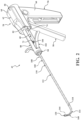
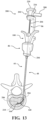
- FIG. 1 shows a system 40 for augmenting a vertebral body.
- An illustration of an axial section of a vertebra (V) is shown with certain structures and regions to be referenced throughout the present disclosure.
- the vertebra (V) includes pedicles (P) on opposing lateral sides of a spinal canal (SC) that provide a generally linear path from a posterior approach to an interior (I) region of the vertebral body (VB).
- the vertebral body (VB) includes a cortical rim (CR) formed from cortical bone that at least partially defines the interior (I) region.
- a volume of cancellous bone (CB) is within the interior (I) region.
- the anatomical directions may also be referenced in accordance with standard medical convention; i.e., medial (M) to the center of the body, lateral (L) to the sides of the body, anterior (A) to the front of the body, and posterior (P) to the rear of the body.
- medial (M) to the center of the body
- lateral (L) to the sides of the body
- anterior (A) to the front of the body
- posterior (P) to the rear of the body.
- the system 40 includes an introducer device 42 and an access cannula 44.
- the access cannula 44 includes a cannula hub 46, and a cannula shaft 48 extending from the cannula hub 46.
- the cannula shaft 48 includes a proximal end 50 coupled to the cannula hub 46, and a distal end 52 opposite the proximal end 50.
- the cannula shaft 48 may be straight and define a lumen (not identified) extending between the proximal and distal ends 50, 52 such that the cannula shaft 48 is tubular in shape.
- the cannula shaft 48 may be formed from biocompatible materials with sufficient mechanical properties to maintain integrity as the cannula shaft 48 is driven through the pedicle of the vertebra.
- the system 40 may include a trocar (not shown) removably positioned within the cannula shaft 48 during placement of the distal end 52 of the cannula shaft 48 into the vertebral body.
- the trocar may include a length slightly greater than a length of the cannula shaft 48 such that a sharp tip of the trocar pierces the cortical bone of the cortical rim, and the trocar prevents coring of tissue within the lumen of the cannula shaft 48.
- the access cannula 44 provides a working channel to within the interior region of the vertebral body along a longitudinal axis (LA) defined by the cannula shaft 48.
- the cannula hub 46 is exposed above the tissue overlying the vertebra, and configured to be engaged by the introducer device 42.
- the housing 56 also includes a frame 62 coupled to the handle 60.
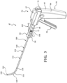
- Figures 1-3 show the frame 62 integrally formed with the handle 60 in a generally L-shaped arrangement.
- the housing 56 may be formed from mirrored housing shells 64, 66 joined together, which be manufactured from polymers, metals, composites, and combinations thereof.
- each of the housing shells 64, 66 may be injection molded so as to be low cost and disposable after a single use.
- the housing shells 64, 66 may at least partially define an interior of the housing 56 sized and shaped to accommodate several components of the actuator 54 to be described.
- the housing 56 may further include a barrel 68 extending distal to (or forward of) the frame 62.
- distal or distally refers to a direction away from the practitioner, and proximal or proximally refers to a direction towards the practitioner.
- the barrel 68 defines a bore in communication with the interior of the housing 56.
- a distal end 70 of the barrel 68 may define a distal end of the actuator 54, and a proximal end 72 of the barrel 68 may be defined by a transition surface 74 extending radially from the barrel 68.
- the engagement of the distal end 70 of the barrel 68 with the coupler 104 of the delivery cannula 100 prevents premature proximal movement of the delivery cannula 100 while the introducer device 42 is being placed within the vertebral body through the access cannula 44.
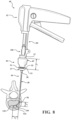
- the introducer device 42 includes a shaft 110 coupled to the actuator 54, and more particularly to the frame 62 of the handle 60.
- the shaft 110 includes a rigid proximal portion 112 and a flexible distal portion 114.
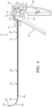
- Figures 4 and 5 show the proximal portion 112 of the shaft 110 extending through the bore of the barrel 68 to a position within the interior of the handle 60.
- the proximal portion 112 of the shaft 110 may be axially and rotationally fixed relative to the actuator 54.
- the proximal portion 112 may be defined between a proximal end 116 of the shaft 110, and an interface 118 between the proximal and distal portions 112, 114 of the shaft 110.
- the distal portion 114 may be defined between the interface 118 and a distal end 120 of the shaft 110 opposite the proximal end 116.
- a length of the shaft 110 may be defined between the proximal and distal ends 116, 120 with the length being sufficient for the shaft 110 to extend through and be operable beyond the distal end 52 of the access cannula 44 as shown in Figure 1 .
- the introducer device 42 is configured to be directed through the access cannula 44 to locations within the interior region of the vertebral body.
- the proximal portion 112 may include rigid material(s) with sufficient mechanical properties to avoid more than minimal flexure. Further, the proximal portion 112 may define a lumen 121 extending between the proximal end 116 of the shaft 110 and the interface 118 such that the proximal portion 112 is tubular in shape with the tubular geometry contributing to its relatively greater stiffness than the geometry of the distal portion 114.
- the distal portion 114 may include a proximal segment 122, a distal segment 124, and a flexing region 126 between the proximal and distal segments 122, 124.
- the proximal segment 122 includes a boss 128 disposed within a complementary bore 130 of the proximal portion 112 of the shaft 110.
- the engagement of the boss 128 and the bore 130 defines the interface 118 joining the proximal and distal portions 112, 114 of the shaft 110, and the joining may be facilitated through brazing, welding, adhesive, or other suitable joining process.
- the proximal segment 122 distal to the boss 128 may be tubular in shape with an outer diameter equal to that of the proximal portion 112 of the shaft 110 to provide a smooth transition across the interface 118.
- the distal segment 124 may also be tubular in shape with an outer diameter equal to that of the proximal segment 122.
- the distal segment 124 defines a channel 132 sized to receive a pulling element 150 of the introducer device 42 to be described.
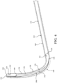
- the flexing region 126 includes a pre-set curve in an unconstrained state to define an inner curved surface 134 opposite an outer curved surface 136. More particularly, a taper 138, 140 at each of the opposing ends of the flexing region 126 define transitions from the flexing region 126 to the proximal and distal segments 122, 124.
- the tapers 138, 140 extend radially inward to form a cavity 142 in communication with the lumen 121 of the proximal portion 112.
- the cavity 142 may be considered an axial bifurcation of a curved segment of a tubular structure.
- the distal portion 114 may include a superelastic shape memory material such as a nickel titanium alloy (i.e., Nitinol).
- the superelastic shape memory material is formed to assume the pre-set curve such that, in the unconstrained state, the superelastic shape memory material moves the distal portion 114 of the shaft 110 upwardly away from the proximal portion 112 of the shaft 110.
- Figure 6 and 7 show the distal portion 114 oriented at an angle of approximately 90 degrees relative to the proximal portion 112.
- the pre-set curve may be designed within the range of approximately 50 to 150 degrees, and more particularly within the range of approximately 65 to 125 degrees, and even more particularly within the range of approximately 80 to 100 degrees. As to be described in greater detail, when the introducer device 42 is directed through the access cannula 44, the pre-set curve facilitates positioning the distal end 120 of the shaft 110 at a location within the vertebral body that is offset from the longitudinal axis.
- the introducer device 42 includes the pulling element 150 coupled to the actuator 54 and the shaft 110.
- the pulling element 150 is configured to be selectively tensioned to alter the extent of the pre-set curve.
- the pulling element 150 includes a proximal end 152 coupled to the actuator 54, and more particularly the control surface 58 of the actuator 54.
- the pulling element 150 may extend through an aperture (not identified) in the control surface 58 and secured proximal to the control surface 58 with an interference connector 78, for example a ferrule, nut, swaged sleeve, clamp, or other suitable connector.
- the connector 78 may be sized to movably ride within a slot defined by complementary pockets 76 in each of the housing shells 64, 66 (one identified in Figures 4 and 5 ).
- An input to the control surface 58 e.g., pulled towards the handle 60 urges the connector 78 proximally within the slot, thereby tensioning the pulling element 150.
- the pulling element 150 includes a distal end 154 opposite the proximal end 152 coupled at or near the distal end 120 of the shaft 110. As best shown in Figures 6 and 7 , the pulling element 150 extends through the lumen 121 of the proximal portion 112 of the shaft 110, along the outer curved surface 136 of the flexing region 126, and through the channel 132 of the distal segment 124.
- the distal end 154 may be coterminous with the distal end 120 of the shaft 110.
- the distal end 154 of the pulling element 150 may be joined at or near the distal end 120 of the shaft 110 through brazing, welding, adhesive, interference fit, or other suitable joining process.
- the pulling element 150 may be monolithic in construction and formed from a metal, polymer, composite, or combination thereof.
- the pulling element 150 may be a wire rope, a wire, a rod, and the like, of solid or hollow construction.
- the flexing region 126 includes the pre-set curve in the unconstrained state, which may include minimal or zero tension being exerted on the pulling element 150. It should be appreciated that some tension may be on the pulling element 150 in the unconstrained state.
- the distal portion 114 of the shaft 110 is oriented, curved, bent, or angled relative to the proximal portion 112 of the shaft 110, as shown in Figures 4 , 6 and 7 .
- the input to the control surface 58 increases the tension on the pulling element 150 to move the pre-set curve to a constrained state in which the distal portion 114, and more particularly the flexing region 126, at least partially straightens.
- the constrained state may include more tension being exerted on the pulling element 150 than the unconstrained state.
- Figure 5 shows the pre-set curve in one example of the constrained state. In a manner to be described, moving the pre-set curve to the constrained state may be indicated for directing the introducer device 42 through and/or removing the introducer device 42 from the access cannula 44.
- the superelastic shape memory material of the distal portion 114 stores potential energy.
- the potential energy stored by the superelastic shape memory material is sufficient to overcome the tension on the pulling element 150 no longer constrained by the input.
- releasing the input to the control surface 58 relaxes ( i.e., reduces the tension on) the pulling element 150, and the pre-set curve moves from the constrained state to the unconstrained state in which the distal portion 114 of the shaft 110 orients, curves, bends, or angles relative to the proximal portion 112 of the shaft 110 to a greater extent than the constrained state.
- the pre-set curve moving from the constrained state to the unconstrained state may displace cancellous bone within the vertebral body, and/or position the distal end 120 of the shaft 110 at a target site that is offset from the longitudinal axis, as shown in Figure 1 .
- a direction of the orientation, curve, bend, or angle may correlate to indicia 79 disposed on a proximal side of the actuator 54, and more particularly the frame 62, thereby visible to the practitioner.
- the actuator 54 may include a locking mechanism 59 operably coupling the housing 56 and the control surface 58 and configured to permit selective locking of the control surface 58 in one of a plurality of positions.
- Figures 4 and 5 show one possible implementation of the locking mechanism 59 as a ratchet including a rack 61 coupled to the control surface 58 configured to engage a pawl 63 coupled to the housing 56.
- the rack 61 is shown as a protrusion extending proximally from the control surface 58 with a plurality of teeth disposed along an arcuate surface.
- the pawl 63 may be a cross-member extending between the housing shells 64, 66 and including an edge configured to releasably engage one of the plurality of teeth of the rack 61.
- Each of the teeth may correspond to one of the plurality of positions in which the control surface 58 may be locked relative to the housing 56. Actuating the locking mechanism 59 to lock the control surface 58 maintains the tension on the pulling element 150, and consequently an extent of the constrained state of the pre-set curve in the plurality of positions. Other possible constructions of the locking mechanism are contemplated.
- the introducer device 42 includes the delivery cannula 100, and the delivery cannula 100 includes a delivery hub 102, the coupler 104 on the delivery hub 102, and a flexible sheath 160 extending from the delivery hub 102.
- the sheath 160 overlies the shaft 110 of the introducer device 42 and, in manners to be further described, performs several functions of the vertebral augmentation, for example, providing a pathway for positioning of a balloon 206 and/or for the delivery of the curable material.
- the sheath 160 includes a proximal end 162 (see Figure 15 ) coupled to the delivery hub 102, and a distal end 164 opposite the proximal end 162 and configured to be positioned at or near the distal end 120 of the shaft 110.
- the distal end 164 of the sheath 160 is slightly proximal to the distal end 120 of the shaft 110.
- the sheath 160 may be tubular in shape and define a lumen 166 sized to slidably and snugly receive the shaft 110 and the pulling element 150. Owing to the presence of the cavity 142 of the flexing region 126, a slight gap may exist within the lumen 166 between the sheath 160 and the outer curved surface 136 of the distal portion 114 of the shaft 110.
- a length of the sheath 160 defined between the proximal and distal ends 162, 164 may be sufficient for the sheath 160 to extend through and be operable beyond the distal end 52 of the access cannula 44, as shown in Figure 1 .
- the sheath 160 is flexible and configured to conform to the shaft 110, and more particularly to the distal portion 114 of the shaft 110.
- the sheath 160 may be formed from a flexible biocompatible polymer having sufficient hoop strength such that the lumen 166 remains patent upon removal of the introducer device 42 from the sheath 160.
- Suitable flexible polymers include polypropylene, polyether ether ketone (PEEK), and the like.
- the sheath 160 may be formed from a flexible biocompatible metal, composite, and combinations thereof, with or without reinforcing features such as filament windings or braids.
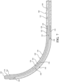
- At least a distal portion 168 of the sheath 160 is configured to conform to the distal portion 114 of the shaft 110 as the pre-set curve is in the constrained state for insertion of the distal portion 114 and the distal portion 168 of the sheath 160 through the lumen of the access cannula 44 to within the vertebral body, and further configured to conform to the distal portion 114 of the shaft 110 as the pre-set curve is moved from the constrained state to the unconstrained state.
- Figure 1 shows the pre-set curve in the unconstrained state with the distal portion 114 of the sheath 160 conforming to the distal portion 114 of the shaft 110.
- the introducer device 42 is removable from the sheath 160 with the distal end 164 of the sheath 160 remaining positioned at the target site offset from the longitudinal axis.
- the aforementioned pathway(s) are achievable to contralateral locations within the vertebral body.
- the pathway(s) facilitate the remaining steps of the vertebral augmentation procedure to be described.
- the vertebra augmentation procedure may include directing an electrode assembly through the sheath 160 with the distal portion 114 of the sheath 160 remaining curved.
- One exemplary electrode assembly that is sufficiently flexible for navigating the curved distal portion 114 is described in United States Patent Publication No. 2013/0006232, published January 3, 2013 .
- the electrode assembly may be bipolar or monopolar. It is contemplated that the electrode assembly may be irrigated such that a fluid is infused into the adjacent tissue prior to and/or during ablation. It is further contemplated that the electrode assembly may be cooled, for example, by circulating a fluid within pathways internal to the electrode assembly. With the electrode assembly being deployed contralaterally, procedures such as intraosseous tumor ablation, basivertebral denervation, and the like, are achievable through a unipedicular approach.
- the vertebra augmentation procedure may include deploying an implant through the sheath 160 with the distal portion 114 of the sheath 160 remaining curved.
- an implant is described in commonly-owned United States Patent No. 7,846,206, issued December 17, 2010 , and commonly-owned United States Patent No. 8,986,386, issued March 24, 2015 .
- the implant may include an intervertebral spacer (i.e., a cage), a mesh bag, or the like, to be deployed within the intervertebral disc space or another appropriate anatomical location, respectively.
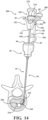
- a workflow of performing a vertebral augmentation with the system 40 will now be described with particular reference to Figure 8-11 , 13 , 14 and 20 .
- the vertebra with the offending vertebral body may be confirmed on fluoroscopic imaging. An incision may be made in the overlying paraspinal musculature lateral of midline generally in alignment with one of the pedicles of the vertebra.
- the distal end 52 of the access cannula 44, with the trocar disposed therein, is directed through the pedicle a position beyond the cortical rim and within the interior region of the vertebral body, and the trocar is removed.
- the access cannula 44 provides the working channel to within the interior region of the vertebral body along the longitudinal axis.
- the cannula hub 46 is exposed and configured to be engaged by the introducer device 42.
- the shaft 110 of the introducer device 42 has a length sufficient to extend through and be operable beyond the distal end 52 of the access cannula 44. Further, the length of the shaft 110 is fixed relative to the actuator 54. Thus, when the introducer device 42 is positioned in operable engagement with the cannula hub 46 of the access cannula 44, the shaft 110 having a fixed length extends beyond the distal end 52 of the cannula shaft 48, also having a fixed length, by a fixed distance. In other words, with the access cannula 44 secured to the vertebra, the cannula hub 46 may be at a fixed distance from the distal end 52 and serve as a datum for subsequently introduced instrumentation.
- the practitioner may be desirable for the practitioner to have the shaft 110 of the introducer device 42 extend beyond the distal end 52 of the access cannula 44 by a distance less than the fixed distance. To do so, the practitioner may manually retract the introducer device 42 proximally relative to the access cannula 44. The arrangement may require the practitioner to manually support and control the introducer device 42, perhaps for prolonged periods, which may be undesirable or unfeasible with deploying additional instrumentation.
- the system 40 of the present disclosure advantageously provides for the access cannula 44 being selectively adjustable such that the datum provided by the access cannula 44 may be selectively tuned.
- the practitioner may position the introducer device 42 in operable engagement with the cannula hub 46, as this is generally preferable, yet selectively control the distance of extension of the shaft 110 of the introducer device 42 from the distal end 52 of the access cannula 44.
- the access cannula 44 that is adjustable is an optional feature of the system 40, and more conventional access cannulas may also be utilized.
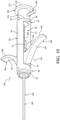
- the cannula hub 46 includes a shaft hub 47, a tuning hub 49, and complementary coupling features 51 movably coupling the tuning hub 49 to the shaft hub 47.
- the shaft hub 47 is rigidly coupled to the cannula shaft 48, and more particularly to the proximal end 50 of the cannula shaft 48.
- Each of the shaft hub 47 and the tuning hub 49 define bores (not identified) coaxially aligned with one another and with the lumen of the access cannula 44 for receiving an elongate member of instrumentation of the system 40, for example, the shaft 110 of the introducer device 42, the sheath 160 of the delivery cannula 100, and/or a balloon tube 204 of the expandable member assembly 200.
- the shaft hub 47 includes a proximally-directed surface 53, and owing to the cannula shaft 48 having a fixed length and being rigidly fixed to the cannula shaft 48, the proximally-directed surface 53 is at a fixed distance from the vertebral body when the distal end 52 of the cannula shaft 48 is positioned within the vertebral body. Thus, it may be considered that the proximally-directed surface 53 provides the datum previously mentioned.
- the tuning hub 49 is movably coupled to the shaft hub 47 with the coupling features 51. Figures 8 and 9 show the coupling features 51 including complementary threading.
- the tuning hub 49 may include a distally-directed surface 55, and an interference surface 57 opposite the distally-directed surface 55.
- the interference surface 57 in a broadest sense, is configured to be engaged by the instrumentation of the system 40, for example, the introducer device 42, the spacer hub 80, the delivery cannula 100, and/or the expandable member assembly 200.
- Figures 8 and 9 show the distal portion 84 of the spacer hub 80 engaging the interference surface 57.
- the interference surface 57 prevents distal movement of the instrument 42, 80, 100, 200 relative to the access cannula 44 while permitting proximal movement of the instrument 42, 80, 100, 200 relative to the access cannula 44.
- a distance from the interference surface 57 to the proximally-directed surface 53 providing the datum contributes to the distance by which the shaft 110 of the introducer device 42 extends from the distal end 52 of the access cannula 44.
- the tuning hub 49 is configured to be supported in a plurality of supported positions to facilitate selective adjustment of an axial position of the interference surface 57 of the tuning hub 49 relative to the datum.
- the tuning hub 49 may be in an initial position (not shown) in which the distally-directed surface 55 of the tuning hub 49 abuts the proximally-directed surface 53 of the shaft hub 47.
- the interference surface 57 of the tuning hub 49 is at a minimum distance from the datum in the initial position.
- the shaft 110 of the introducer device 42 extends from the distal end 52 of the access cannula 44 by an initial length, which may be resolved in an x-component along the longitudinal axis and a y-component perpendicular to the longitudinal axis.
- the initial distance may be a greatest length by which the shaft 110 of the introducer device 42 extends from the distal end 52 of the access cannula 44.
- the practitioner may selectively tune the access cannula 44 to selectively adjust the axial position of the interference surface 57 relative to the datum.
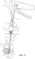
- the practitioner may proximally move the tuning hub 49 relative to the shaft hub 47 to a first position in which the interference surface 57 is at a first distance (d 1 ) from the datum provided by the shaft hub 47, as shown in Figure 8 .
- the selective adjustment of the interference surface 57 may be facilitated by the coupling features 51, for example the complementary threads, which move the tuning hub 49 relative to the shaft hub 47 upon receiving a twisting input from the practitioner.
- the shaft 110 of the introducer device 42 extends from the distal end 52 of the access cannula 44 by a first length, which may be resolved in the x-component (x 1 ) and the y-component (y 1 ).
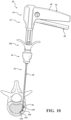
- the practitioner may proximally move the tuning hub 49 relative to the shaft hub 47 to a first supported position in which the interference surface 57 is at a second distance (d 2 ) from the datum provided by the shaft hub 47, as shown in Figure 9 .
- the shaft 110 of the introducer device 42 extends from the distal end 52 of the access cannula 44 by a second length, which may be resolved in the x-component (x 2 ) and the y-component (y 2 ). It is appreciated that that second length is less than the first length in each of the x- and y-components, as the second distance is greater than the first distance, which increases an overall length of the access cannula 44 defined between the interference surface 57 and the distal end 52.
- the instrument 42, 100, 200 may be the delivery cannula 100 including the delivery hub 102 and the sheath 160 extending from the delivery hub 102.
- Figures 8 and 9 show the delivery hub 102 abutting the distal portion 84 of the spacer hub 80, which is engaging the interference surface 57 of the tuning hub 49.
- the interference surface 57 may be selectively adjusted to move the distal end 164 of the sheath 160 relative to the distal end 52 of the access cannula 44.
- Figure 8 shows the distal end 164 of the sheath 160 at the first length, resolved in the x- and y-components (x 1 , y 1 ), with the interference surface 57 at the first distance (d 1 ) from the datum
- Figure 9 shows the distal end 164 of the sheath 160 at the second length, resolved in the x- and y-components (x 2 , y 2 ), with the interference surface 57 at the second distance (d 2 ) from the datum.
- the practitioner may enjoy the benefit of engaging the instrument 42, 100, 200 with the access cannula 44 (e.g., abutting, removably coupling, etc.), and achieving a desired length of extension of the instrument 42, 100, 200 from the distal end 52 of the access cannula 44 without needing to manually retract or support the instrument 42, 100, 200.
- the access cannula 44 e.g., abutting, removably coupling, etc.
- the introducer device 42 including the sheath 160, is directed through the access cannula 44 in the manner previously described.
- the introducer device 42 may be provided with the pre-set curve in the unconstrained state, and the distal portion 168 of the sheath 160 conforming to the pre-set curve.
- the superelastic shape memory material biases the distal portion 114 of the shaft 110, along with the distal portion 168 of the sheath 160, away from an axis of the proximal portion 112 of the shaft 110.
- the practitioner provides an input to the actuator 54, for example moving the control surface 58 towards the handle 60, to increase the tension the pulling element 150.
- the tensioning of the pulling element 150 moves the pre-set curved from the unconstrained state to the constrained state against the biasing force from the superelastic shape memory material.
- the pre-set curve at least partially straightens along with the distal portion 168 of the sheath 160. More particularly, the pre-set curve straightens to an extent that the distal portion 114 of the shaft 110 and the distal portion 168 of the sheath 160 may be directed through the lumen of the access cannula 44. It is understood that the distal portion 114 of the shaft 110 need not be entirely straight, as the access cannula 44 constrains the distal portion 114 as it is advanced therethrough.
- distal portion 114 of the shaft 110 should be straightened to an extent to permit ease with insertion of the shaft 110 and the sheath 160 along the lumen of the access cannula 44 as it is advanced therethrough.
- the pre-set curve may be selectively locked with the locking mechanism 59.
- the shaft 110 of the introducer device 42 and the sheath 160 of the delivery cannula 100 are directed through the access cannula 44 in the constrained state.
- Another input is provided to the actuator 54, which may be considered removal of the earlier input.
- the removal of the input may be performed quickly or in a controlled manner.
- the pulling element 150 is relaxed, and/or the tension on the pulling element 150 is reduced.
- the superelastic shape memory material releases the stored potential energy to move the pre-set curve from the constrained state to the unconstrained state.
- the removal of the input may be performed when the distal end 120 of the shaft 110 is at least substantially in registration with the distal end 52 of the access cannula 44.
- the pre-set curve may not be constrained from the pulling element 150 but otherwise constrained from the cannula shaft 48 of the access cannula 44.
- the introducer device 42 and the sheath 160 are advanced distally relative to the access cannula 44 to position the distal portion 114 of the shaft 110 and the distal portion 168 of the sheath 160 within the interior of the vertebral body.
- any number of subsequent inputs may be provided to the control surface 58 to selectively adjust the curvature of the distal portion 114 of the shaft 110 and the distal portion 168 of the sheath 160, and multiple inputs may be provided for creating a cavity of a desired shape within the interior region of the vertebral body.
- relative positions between the radiopaque markers 170 may be viewable on the x-ray imaging to determine a curvature of the distal portion 168 of the sheath 160.
- utilizing the lateral and A/P x-ray imaging in tandem in the aforementioned manner facilitates visually ascertaining and/or confirming intraoperatively the position and/or the curvature of the distal portion 168 of the sheath 160 within the interior region of the vertebral body, particularly in three-dimensions.
- the lateral x-ray images provide the practitioner with precise positional information in the cranial (CR) and anterior (A) directions, and additional deducible information in the lateral (L) direction ( i.e., based on practicioner experience assessing the relative positions between the radiopaque markers 170).
- the A/P x-ray images provide the practitioner with precise positional information in the cranial (CR) and lateral (L) directions, and additional deducible information in the anterior (A) direction.
- the practitioner is able to view the x-ray image set on the display 172 and readily ascertain the position and/or curvature of the distal portion 168 of the sheath 160 within the interior region of the vertebral body.
- the spacer hub 80 includes a distal portion 84 configured to engage the cannula hub 46, and more particularly the tuning hub 49, as shown in Figure 1 .
- the distal portion 84 may include a boss 85 sized to be seated within a complementary cavity in the cannula hub 46 (see Figures 18 and 19 ).
- Each of the distal portion 84 and the cannula hub 46 may include complementary coupling features (not shown), for example a releasable detent, configured to removably couple the spacer hub 80 to the access cannula 44.
- the spacer hub 80 further includes the proximal portion 82 configured to be engaged by the balloon hub 202, as best shown in Figures 13-15 .
- the syringe-style input may include one of the first control surfaces 107 is engaged by the index finger of the practitioner, the other one of the first control surfaces 107 being engaged by the middle finger of the practitioner, and the second control surface 220 being engaged by the thumb of the practitioner.
- the arrangement and ergonomics may be similar to the medical syringe, and thus the arrangement is intuitive to the practitioner.
- the syringe-style input may include the thumb maintaining the position of the expandable member assembly 200 while at least one finger actuates first the control surface 107 to draw the delivery hub 102 towards the balloon hub 202.
- Constraining the delivery hub 102 from rotation prevents the sheath 160 from correspondingly rotating within the vertebral body, which may prevent kinking of the sheath 160 and/or prevent the sheath 160 from deviating from its existing path or curvature. Further, the wings 106 remaining in a fixed rotational position may instill confidence to the practitioner that the curvature of the distal portion 168 of the sheath 160 is correspondingly fixed.
- the spacer hub 80 may be configured to pivot for exposing the coupler 104 of the delivery hub 102 for coupling of a cement delivery system 230 to be described.
- the spacer hub 80 may include a pivot 95 pivotably coupling the distal portion 84 to the proximal portion 82.
- Each of the proximal and distal portions 82, 84 may include a surface 94 a , 94 b collectively forming the side 94 of the spacer hub 80.
- the pivot 95 couples the surfaces 94 a, 94 b such that, when the spacer hub 80 is provided between a first position shown in Figure 17 and a second position shown in Figure 19 , the proximal portion 82 articulates in a direction away from the void space 86.
- the spacer hub 80 may be generally U-shaped when in the first position with the surfaces 94 a, 94 b generally aligned, for example coplanar.
- the proximal portion 82 may substantially inverted and the surfaces 94 a, 94 b are parallel.
- the cement delivery system 230 may include a housing 232, a first control surface 234 coupled to the housing, and a second control surface 236 coupled to the housing 232.
- the first and second control surfaces 234, 236 are configured to receive inputs from the practitioner. For example, a rotational input to the first control surface 234 with one hand of the practitioner may advance a piston (not shown) with a chamber 238 to urge the curable material through the system 230.
- An input to the second control surface 236 with the other hand of the practitioner may be required to permit advancement of the piston, and release of the input to the second control surface 236 may act as a "dead man's switch" for ceasing distal movement of the piston (and permitting proximal movement of the piston).
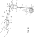
- the cement delivery system 230 may include an extension tube 240 is adapted to be coupled to the coupler 104 of the delivery cannula 100, as shown in Figure 20 .
- the extension tube 240 includes a proximal coupler 242 coupled to the chamber 238, and a distal coupler 244 coupled to the coupler 104.
- the arrangement establishes communication between the chamber 238 and the sheath 160 of the delivery cannula 100.
- One or both of the proximal and distal couplers 242, 244 may be pivotable, and additional segments of tubing may be provided. Further construction of the extension tube 240 is disclosed in the aforementioned United States Provisional Patent Application No. 62/656,033 .
- the spacer hub 80 is moved from the first position to the second position.
- the distal coupler 244 of the extension tube 240 may be coupled to the coupler 104 of the delivery cannula 100, and the cement delivery system 230 operated to direct the curable material (CM) from the chamber 238 through the delivery hub 102, through the sheath 160 including the distal portion 168 in the curve configuration, and into the cavity (CA) within the interior region of the vertebral body.
- the sheath 160 may be proximally retracting while the curable material is being delivered so as to move the distal end 164 of the sheath 160 and locate the entry point of the curable material as desired.
- the spacer hub 80 may be returned from the second position to the first position to facilitate the practitioner utilizing the syringe-style input previously described.
- the delivery cannula 100 is removed from the access cannula 44.
- the trocar may be reintroduced through the access cannula 44, and the access cannula 44 and trocar removed from the vertebral body.
- the overlying tissue may be sutured.
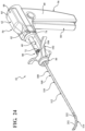
- FIG. 23 shows the introducer device 250 in a first or slack configuration
- Figure 24 shows the introducer device 250 in a second or tensioned configuration.
- the distal portion 114 of the shaft 110 includes a plurality of links 252 interconnected to one another and configured to articulate relative to one another.
- a system for augmenting a vertebral body includes an introducer device includes an actuator configured to receive an input from a user, a shaft including a rigid proximal portion coupled to the actuator and defining a proximal end of the shaft and a flexible distal portion including a pre-set curve in an unconstrained state, and a pulling element coupled to the actuator and to the shaft at or near the distal end with the pulling element extending along at least a portion of the pre-set curve, wherein tension on the pulling element is configured to be increased in response to the input to provided to the actuator to move the pre-set curve from the unconstrained state to a constrained state in which the flexible distal portion at least partially straightens, and wherein the tension on the pulling element is configured to be reduced to the unconstrained state to position the distal end of the shaft within the vertebral body at a target site that is offset from the longitudinal axis; a flexible sheath at least partially overlying the shaft with the flexible sheath having a distal end
- the system may include a biasing element operably coupled to the pulling element and the actuator with the biasing element configured to be at least initially in a stressed state to bias the pulling element to the constrained state, wherein the biasing element is further configured to relax in response to the input to provided to the actuator to facilitate altering the tension on the pulling element to permit the flexible distal portion to move to the unconstrained state.
- the biasing element may be, for example, a compression spring.
- the compression spring may be in the stressed state, for example, stretched relative to its natural length. The forces from the compression spring are sufficient to overcome the forces associated with the pre-set curve biased towards the unconstrained state such that the compression spring maintains the pre-set curve in the constrained state in which the flexible distal portion at least mostly straight.
- the compressing spring may be relaxed such that the tension on the pulling element is reduced, and the pre-set curve moves from the constrained state to the unconstrained state.
Landscapes
- Health & Medical Sciences (AREA)
- Surgery (AREA)
- Life Sciences & Earth Sciences (AREA)
- Orthopedic Medicine & Surgery (AREA)
- Heart & Thoracic Surgery (AREA)
- Veterinary Medicine (AREA)
- Engineering & Computer Science (AREA)
- Biomedical Technology (AREA)
- Nuclear Medicine, Radiotherapy & Molecular Imaging (AREA)
- Medical Informatics (AREA)
- Molecular Biology (AREA)
- Animal Behavior & Ethology (AREA)
- General Health & Medical Sciences (AREA)
- Public Health (AREA)
- Pathology (AREA)
- Dentistry (AREA)
- Oral & Maxillofacial Surgery (AREA)
- Surgical Instruments (AREA)
- Prostheses (AREA)
Description
- A common source of back pain is a vertebral compression fracture in which a weakened or injured vertebral body loses height or collapses. The weakening of the vertebral body may be due to acute injury or, more often, degenerative changes such as osteoporosis. The compression fractures often appear on lateral radiographs as wedge deformities with greater loss of height anteriorly.
- One treatment modality includes vertebral augmentation in which the height of the vertebral body is elevated or restored, and stabilized at the elevated or restored height. A vertebroplasty includes delivering curable material, for example a bone cement, within an interior of the vertebral body. The material interdigitates with cancellous bone and cures to stabilize the vertebral body. A kyphoplasty includes creating a cavity within the interior of the vertebral body by compressing the cancellous bone with an expandable member such as a balloon, and delivering the curable material into the cavity. The expandable member may facilitate elevating or restoring the height of the vertebral body.
- Accessing the interior of the vertebral body often includes percutaneously placing an access cannula through a pedicle of the vertebra. Owing to the structure of the vertebra, accessing a location on the contralateral side of the vertebral body is not especially feasible with straight instrumentation. As such, one existing kyphoplasty technique employs a bipedicular approach in which two access cannulas are placed, followed by two balloons each positioned ipsilaterally within the interior of the vertebral body. The bipedicular approach undesirably requires twice the trauma to tissue, and often requires twice the instrumentation.
- Of particular interest is a unipedicular approach in which the instrumentation is designed to access locations of the interior of the vertebral body offset from a longitudinal axis of the access cannula, including locations on the contralateral side of the vertebral body. One exemplary system utilizing the unipedicular approach is disclosed in commonly owned
United States Patent No. 8,894,658, issued November 25, 2014 , and sold under the tradename Avaflex by Stryker Corporation (Kalamazoo, Mich.). While the disclosure realizes the benefits of the unipedicular approach, there is further need in the art for systems and methods for off-axis vertebral augmentation. - Document
US 2011/0295262 A1 describes methods and devices that displace bone or other hard tissue to create a cavity in the tissue. Such methods and devices rely on a driving mechanism for providing moving of the device to from a profile that improves displacement of the tissue. These methods and devices also allow for creating a path or cavity in bone for insertion of bone cement or other filler to treat a fracture or other condition in the bone. The features relating to the methods and devices can be applied in any region of bone or hard tissue where the tissue or bone is displaced to define a bore or cavity instead of being extracted from the body such as during a drilling or ablation procedure. - Claim 1 is directed to a system for augmenting a vertebral body. The system includes an access cannula, and introducer device, and a flexible sheath. The access cannula includes a cannula hub, and a cannula shaft extending from the cannula hub. The cannula shaft includes a distal end positionable within the vertebral body and defining a lumen along a longitudinal axis. The introducer device includes an actuator configured to receive an input from a user, and a shaft. The shaft includes a rigid proximal portion coupled to the actuator and defining a proximal end of the shaft, and a flexible distal portion. A length of the shaft between the proximal end and a distal end is sufficient for the shaft to extend through and be operable beyond the distal end of the access cannula. The flexible distal portion includes a pre-set curve in an unconstrained state. The introducer device includes a pulling element coupled to the actuator and to the shaft at or near the distal end. The pulling element extends along at least a portion of the pre-set curve. A distal portion of said flexible sheath is configured to conform to said flexible distal portion as said pre-set curve is moved between said constrained state and said unconstrained state. According to claim 3, tension on the pulling element is configured to be increased in response to the input provided to the actuator to move the pre-set curve from the unconstrained state to a constrained state in which the flexible distal portion at least partially straightens. In further accordance with claim 3, the tension on the pulling element is configured to be reduced to facilitate the pre-set curve moving from the constrained state to the unconstrained state to position the distal end of the shaft within the vertebral body at a target site that is offset from the longitudinal axis. The flexible sheath of the system of claim 1 at least partially overlying the shaft with the flexible sheath including a distal end positionable near the distal end of the shaft such that the flexible sheath is configured to extend through and be operable beyond the distal end of the access cannula with a distal portion of the flexible sheath conforming to the flexible distal portion as the pre-set curve moves between the constrained state and the unconstrained state, wherein the introducer device is removable from the flexible sheath with the distal end of the flexible sheath remaining at the target site offset from the longitudinal axis.
- In some implementations of the system of claim 3, the pre-set curve defines an inner curved surface opposite an outer curved surface. The pulling element may extend along at least a portion of the outer curved surface. The introducer device may include a housing, and a locking mechanism operably coupling the housing and the actuator, wherein the locking mechanism is configured to permit selective locking of the actuator in one of a plurality of positions.
- In some implementations of the system of claim 3, the system includes an expandable member assembly including a balloon hub, a balloon tube extending from the balloon hub, and a balloon coupled to a distal end of the balloon tube. The balloon hub is adapted to be coupled to a fluid source. The balloon tube may be sized to be slidably inserted within the flexible sheath. The balloon may be configured to be inflated with fluid from the fluid source to displace cancellous bone within the vertebral body. The balloon tube has a length such that the balloon is positioned proximate the distal end of the flexible sheath when the balloon tube is slidably inserted within the flexible sheath.
- An exemplary aspect of the disclosure involves a method of operating the system according to the first example (the method is described herein to aid understanding the invention, but not claimed), and optionally, any of its corresponding implementations.
- An exemplary further aspect of the present disclosure is directed to a system for augmenting a vertebral body. The system includes an access cannula, a delivery cannula, an expandable member assembly, and a spacer hub. The access cannula includes a cannula hub, and a cannula shaft extending from the cannula hub. The cannula shaft includes a distal end positionable within the vertebral body. The delivery cannula includes a delivery hub, and a sheath extending from the delivery hub. The sheath includes a distal end opposite a proximal end collectively defining a length sufficient to extend through and be operable beyond the distal end of the access cannula. The delivery hub is movable relative to the cannula hub such that the sheath is slidably disposed within the cannula shaft. The expandable member assembly includes a balloon hub adapted to be coupled to a fluid source. A balloon tube extends from the balloon hub and is sized to be slidably inserted within the sheath. A balloon is coupled to a distal end of the balloon tube and configured to be inflated with fluid from the fluid source to displace cancellous bone within the vertebral body. The spacer hub is configured to facilitate proximal movement of the delivery cannula relative to the access cannula and the expandable member assembly. The sheath is retracted to expose the balloon within the vertebral body through a syringe-style input from a user. The spacer hub includes a distal portion engaging the cannula hub and a proximal portion for engaging the balloon hub. The distal and proximal portions include opposing stop surfaces defining a void space with the delivery hub configured to be movably disposed within the void space such that the opposing stop surfaces provide a terminus of movement of the delivery hub.
- In some implementations, the system includes a biasing element operably coupled to the pulling element and the actuator. The biasing element may be configured to be at least initially in a stressed state to bias the pulling element to the constrained state. The biasing element may be further configured to relax in response to the input to provided to the actuator to facilitate altering the tension on the pulling element to permit the flexible distal portion to move to the unconstrained state.
- An exemplary further aspect of the disclosure is directed to a system for augmenting a vertebral body. The system includes an access cannula, a delivery cannula, an expandable member assembly, and a spacer hub. The access cannula includes a cannula hub, and a cannula shaft extending from the cannula hub. The cannula shaft includes a distal end positionable within the vertebral body. The delivery cannula includes a delivery hub, and a sheath extending from the delivery hub. The sheath includes a distal end opposite a proximal end collectively defining a length sufficient to extend through and be operable beyond the distal end of the access cannula. The delivery hub is movable relative to the cannula hub such that the sheath is slidably disposed within the cannula shaft. The expandable member assembly includes a balloon hub adapted to be coupled to a fluid source. A balloon tube extends from the balloon hub and sized to be slidably inserted within the sheath. A balloon is coupled to a distal end of the balloon tube and configured to be inflated with fluid from the fluid source to displace cancellous bone within the vertebral body. The spacer hub is configured to facilitate proximal movement of the delivery cannula relative to the access cannula and the expandable member assembly. The sheath is retracted to expose the balloon within the vertebral body through a syringe-style input from a user. The spacer hub includes a distal portion engaging the cannula hub, a proximal portion configured to engage the balloon hub, and a pivot pivotably coupling the distal portion to the proximal portion.
- In some implementations, the balloon hub includes a body portion, a transition surface configured to engage the proximal portion of the spacer hub, and a control surface opposite the transition surface and sized to receive a thumb of the user to facilitate providing the syringe-style input. The delivery hub may define a lumen and each of the distal and proximal portions of the spacer hubs define coaxial apertures. At least a portion of the balloon tube may extend through the lumen and the coaxial apertures such that the delivery hub is slidable along the balloon tube between the distal and proximal portions of the spacer hub. At least one side may extend between the distal and proximal portions. The side(s) may be two sides defining opposed slots extending between the distal and proximal portions. The delivery hub comprises wings extending through the opposed slots and configured to receive the syringe-style input from the user.
- In some implementations, the spacer hub includes a pivot pivotably coupling the distal portion and the proximal portion. The delivery hub may include a coupler defining an opening in communication with the sheath, wherein pivoting the proximal portion relative to the distal portion exposes the coupler for removably coupling a cement delivery system with the coupler.
- In some implementations, the spacer hub is configured to be operable with the system according to the first aspect of the present disclosure, and optionally, any of its corresponding implementations.
- An exemplary further aspect of the disclosure involves a method of operating the system according to the third example (the method is described herein to aid understanding the invention, but not claimed), and optionally, any of its corresponding implementations.
- An exemplary further aspect of the disclosure is directed to a system for augmenting a vertebral body. The system includes an access cannula and an instrument. The access cannula includes a cannula shaft includes a distal end positionable within the vertebral body that defines a lumen along a longitudinal axis. A cannula hub includes a shaft hub rigidly coupled to the cannula shaft, and a tuning hub movably coupled to the shaft hub. The shaft hub is at a fixed distance from the vertebral body when the distal end of the cannula shaft is positioned within the vertebral body to provide a datum. The tuning hub includes an interference surface movable relative to the shaft hub between plurality of supported positions. The instrument includes an elongate member slidably disposed within the lumen of the cannula shaft and includes a length defined between proximal and distal ends being sufficient for the elongate member to extend through and be operable beyond the distal end of the access cannula. An instrument hub is coupled to the proximal end of the elongate member. The cannula hub is configured to be engaged by the instrument hub to prevent distal movement of the instrument relative to the access cannula while permitting proximal movement of the instrument relative to the access cannula. The movement of the tuning hub relative to the shaft hub to one of the plurality of supported positions facilitates selective adjustment of an axial position of the interference surface of the tuning hub relative to the datum.
- In some implementations, each of the shaft hub and the tuning hub may include complementary threading for permitting the selective adjustment of the interference surface through a twisting input from the user. Each of the shaft hub and the tuning hub may define apertures coaxially aligned with the lumen with at least one of the instrument hub and the elongate member extending through the coaxial apertures. The instrument may be one of an introducer device, a delivery cannula, and an expandable member assembly.
- In some implementations, the instrument hub is configured to be operable with the systems according to the first and third aspects of the present disclosure, and optionally, any of their corresponding implementations.
- An exemplary further aspect of the disclosure is directed to a method of operating the system according to the fifth example (the method is described herein to aid understanding the invention, but not claimed), and optionally, any of its corresponding implementations.
- In some implementations of claim 3, at least two radiopaque markers are disposed on the distal portion of the flexible sheath and spaced apart from one another. As the distal portion is curved within the vertebral body, relative positions between the at least two radiopaque markers are viewable on radiography to determine a curvature of the curve.
- In some implementations the radiopaque markers are exactly two radiopaque markers. The radiopaque markers may be one of dots, bands, rings, and lines.
- In some implementations, the radiopaque markers are configured to be operable with the systems according to the first, third, fifth and seventh aspects of the present disclosure, and optionally, any of their corresponding implementations.
- Another exemplary aspect of the disclosure is directed to a method of operating the system according to the seventh example (the method is described herein to aid understanding the invention, but not claimed), and optionally, any of its corresponding implementations.
- The present invention is defined in claim 1 while preferred embodiments are set forth in the dependent claims.
- Associated methods are also described herein to aid understanding the invention. Advantages of the present invention will be readily appreciated as the same becomes better understood by reference to the following detailed description when considered in connection with the accompanying drawings.
-
Figure 1 shows a system for augmenting a vertebral body. An access cannula is directed through a pedicle of the vertebra, and an introducer device and a flexible sheath extend through the access cannula. A pre-set curve of a shaft of the introducer device is in an unconstrained state within the vertebral body. -
Figure 2 is a front perspective view of the introducer device. The flexible sheath is shown in phantom. -
Figure 3 is a rear perspective view of the introducer device ofFigure 2 . -
Figure 4 is a sectional view of the introducer device ofFigure 2 with the pre-set curve of the shaft shown in an unconstrained state. -
Figure 5 is another sectional view of the introducer device with the pre-set curve of the shaft shown in a constrained state. -
Figure 6 is a perspective view of a portion of the shaft of the introducer device with a portion of the flexible sheath shown in phantom. -
Figure 7 is a sectional view of the portion of the shaft and the flexible sheath ofFigure 6 . -
Figure 8 shows the shaft and the flexible sheath of the introducer device extending through an access cannula adjustable to a first distance, and a distal end of the introducer device at a first position within the vertebral body based on the first distance of the adjustable access cannula. -
Figure 9 shows the shaft and the flexible sheath of the introducer device extending through the access cannula adjustable to a second distance, and a distal end of the introducer device at a second position off-axis within the vertebral body based on the second distance of the adjustable access cannula. -
Figure 10 shows the shaft and the flexible sheath of the introducer device extending through the access cannula with the actuator actuated and the pre-set curve of the shaft in the constrained state within the vertebral body. -
Figure 11 shows the shaft and the flexible sheath of the introducer device extending through the access cannula with the pre-set curve of the shaft in the unconstrained state within the vertebral body. -
Figure 12 is a schematic representation of five sets of lateral and anterior-posterior (A-P) x-ray images showing relative positions of the radiopaque markers of the flexible sheath in each of five configurations within the vertebral body. -
Figure 13 shows a flexible distal portion of the flexible sheath in a curved configuration with an expandable member assembly including a balloon removably positioned within the flexible distal portion. A spacer hub engaging the access cannula is in a first position, and a delivery hub coupled to the flexible sheath is spaced apart from a balloon hub of the expandable member assembly. -
Figure 14 shows the flexible distal portion of the flexible sheath in the curved configuration. The spacer hub engaging the access cannula is in the first position. The delivery hub is moved towards the balloon hub to retract the flexible sheath and expose the balloon within the vertebral body. -
Figure 15 is a detailed perspective view of the balloon hub and the delivery hub operably coupled to a spacer hub. -
Figure 16 is a perspective view of the spacer hub ofFigure 15 . -
Figure 17 is a perspective view of the spacer hub ofFigures 13 and14 . -
Figure 18 is an elevation view of the spacer hub ofFigure 17 in the first position. The access cannula and a delivery cannula including the flexible sheath are shown in phantom. -
Figure 19 is an elevation view of the spacer hub ofFigure 17 in a second position. The access cannula and a delivery cannula including the flexible sheath are shown in phantom. -
Figure 20 shows the spacer hub in the second position, and a cement delivery system operably coupled to the delivery hub of the delivery cannula delivers bone cement within the vertebral body. -
Figure 21 is a front perspective view of the balloon hub of the expandable member assembly. -
Figure 22 is a rear perspective view of the balloon hub of the expandable member assembly. -
Figure 23 is a front perspective view of the introducer device for a system for augmenting a vertebral body. The flexible sheath overlying the shaft is shown in phantom. -
Figure 24 is a front perspective view of the introducer device ofFigure 21 with the actuator actuated and the shaft and the flexible sheath in a curved configuration. -
Figure 1 shows asystem 40 for augmenting a vertebral body. An illustration of an axial section of a vertebra (V) is shown with certain structures and regions to be referenced throughout the present disclosure. The vertebra (V) includes pedicles (P) on opposing lateral sides of a spinal canal (SC) that provide a generally linear path from a posterior approach to an interior (I) region of the vertebral body (VB). The vertebral body (VB) includes a cortical rim (CR) formed from cortical bone that at least partially defines the interior (I) region. A volume of cancellous bone (CB) is within the interior (I) region. With reference to the compass rose ofFigure 1 , the anatomical directions may also be referenced in accordance with standard medical convention; i.e., medial (M) to the center of the body, lateral (L) to the sides of the body, anterior (A) to the front of the body, and posterior (P) to the rear of the body. - The
system 40 includes anintroducer device 42 and anaccess cannula 44. Theaccess cannula 44 includes acannula hub 46, and acannula shaft 48 extending from thecannula hub 46. Thecannula shaft 48 includes aproximal end 50 coupled to thecannula hub 46, and adistal end 52 opposite theproximal end 50. Thecannula shaft 48 may be straight and define a lumen (not identified) extending between the proximal and distal ends 50, 52 such that thecannula shaft 48 is tubular in shape. Thecannula shaft 48 may be formed from biocompatible materials with sufficient mechanical properties to maintain integrity as thecannula shaft 48 is driven through the pedicle of the vertebra. Thesystem 40 may include a trocar (not shown) removably positioned within thecannula shaft 48 during placement of thedistal end 52 of thecannula shaft 48 into the vertebral body. The trocar may include a length slightly greater than a length of thecannula shaft 48 such that a sharp tip of the trocar pierces the cortical bone of the cortical rim, and the trocar prevents coring of tissue within the lumen of thecannula shaft 48. Once thedistal end 52 of thecannula shaft 48 is positioned within the vertebral body, for example as shown inFigure 1 , the trocar is removed. Theaccess cannula 44 provides a working channel to within the interior region of the vertebral body along a longitudinal axis (LA) defined by thecannula shaft 48. Thecannula hub 46 is exposed above the tissue overlying the vertebra, and configured to be engaged by theintroducer device 42. - With further reference to
Figures 2 and3 , theintroducer device 42 includes anactuator 54. Theactuator 54 is configured to receive an input from a practitioner or user to actuate theintroducer device 42 in a manner to be further described. Theactuator 54 includes ahousing 56, and acontrol surface 58 movably coupled to thehousing 56.Figures 1-3 show thehousing 56 and thecontrol surface 58 in a "pistol-grip" arrangement in which ahandle 60 of thehousing 56 is configured to rest in a palm of a hand of the practitioner, and thecontrol surface 58 configured to be pulled towards or released away from thehandle 60 with one or more fingers of the hand of the practitioner. Other arrangements of theactuator 54 are contemplated, for example a rotary knob disclosed in commonly ownedUnited States Patent Publication No. 2016/0228131, filed April 13, 2016 . Thehousing 56 also includes aframe 62 coupled to thehandle 60.Figures 1-3 show theframe 62 integrally formed with thehandle 60 in a generally L-shaped arrangement. Thehousing 56 may be formed from mirroredhousing shells housing shells housing shells housing 56 sized and shaped to accommodate several components of theactuator 54 to be described. - The
housing 56 may further include abarrel 68 extending distal to (or forward of) theframe 62. As used herein, distal or distally refers to a direction away from the practitioner, and proximal or proximally refers to a direction towards the practitioner. Thebarrel 68 defines a bore in communication with the interior of thehousing 56. A distal end 70 of thebarrel 68 may define a distal end of theactuator 54, and aproximal end 72 of thebarrel 68 may be defined by atransition surface 74 extending radially from thebarrel 68.Figures 1 and2 show thebarrel 68 being cylindrical in shape between the proximal and distal ends 70, 72 and having an outer diameter sized to be slidably and removably inserted through aproximal portion 82 of aspacer hub 80 to be described. With thetransition surface 74 engaging theproximal portion 82 of thespacer hub 80, as best shown inFigure 2 , a length of thebarrel 68 defined between the proximal and distal ends 70, 72 may be sufficient to engage or abut acoupler 104 of adelivery cannula 100. The engagement of the distal end 70 of thebarrel 68 with thecoupler 104 of thedelivery cannula 100 prevents premature proximal movement of thedelivery cannula 100 while theintroducer device 42 is being placed within the vertebral body through theaccess cannula 44. - The
introducer device 42 includes ashaft 110 coupled to theactuator 54, and more particularly to theframe 62 of thehandle 60. Theshaft 110 includes a rigidproximal portion 112 and a flexibledistal portion 114.Figures 4 and5 show theproximal portion 112 of theshaft 110 extending through the bore of thebarrel 68 to a position within the interior of thehandle 60. Theproximal portion 112 of theshaft 110 may be axially and rotationally fixed relative to theactuator 54. Theproximal portion 112 may be defined between aproximal end 116 of theshaft 110, and aninterface 118 between the proximal anddistal portions shaft 110. Thedistal portion 114 may be defined between theinterface 118 and adistal end 120 of theshaft 110 opposite theproximal end 116. A length of theshaft 110 may be defined between the proximal anddistal ends shaft 110 to extend through and be operable beyond thedistal end 52 of theaccess cannula 44 as shown inFigure 1 . As such, theintroducer device 42 is configured to be directed through theaccess cannula 44 to locations within the interior region of the vertebral body. - The
proximal portion 112 may include rigid material(s) with sufficient mechanical properties to avoid more than minimal flexure. Further, theproximal portion 112 may define alumen 121 extending between theproximal end 116 of theshaft 110 and theinterface 118 such that theproximal portion 112 is tubular in shape with the tubular geometry contributing to its relatively greater stiffness than the geometry of thedistal portion 114. In particular and with further reference toFigures 6 and7 , thedistal portion 114 may include aproximal segment 122, adistal segment 124, and a flexingregion 126 between the proximal anddistal segments proximal segment 122 includes aboss 128 disposed within acomplementary bore 130 of theproximal portion 112 of theshaft 110. The engagement of theboss 128 and thebore 130 defines theinterface 118 joining the proximal anddistal portions shaft 110, and the joining may be facilitated through brazing, welding, adhesive, or other suitable joining process. Theproximal segment 122 distal to theboss 128 may be tubular in shape with an outer diameter equal to that of theproximal portion 112 of theshaft 110 to provide a smooth transition across theinterface 118. Thedistal segment 124 may also be tubular in shape with an outer diameter equal to that of theproximal segment 122. Thedistal segment 124 defines a channel 132 sized to receive a pullingelement 150 of theintroducer device 42 to be described. - The flexing
region 126 includes a pre-set curve in an unconstrained state to define an innercurved surface 134 opposite an outercurved surface 136. More particularly, ataper region 126 define transitions from the flexingregion 126 to the proximal anddistal segments tapers cavity 142 in communication with thelumen 121 of theproximal portion 112. In other words, thecavity 142 may be considered an axial bifurcation of a curved segment of a tubular structure. The outercurved surface 136 may define a portion of thecavity 142, and the innercurved surface 134 may appear as a smooth transition between the proximal anddistal segments curved surface 134 is somewhat convex-concave in geometry. Thecavity 142 results in the flexingregion 126 being thin in thickness along its length (relative to width), the flexingregion 126 is configured to flex or bend about its minor axis between, for example, the configurations shown inFigures 4 and5 . - The
distal portion 114, and more particularly at least the flexingregion 126, may include a superelastic shape memory material such as a nickel titanium alloy (i.e., Nitinol). The superelastic shape memory material is formed to assume the pre-set curve such that, in the unconstrained state, the superelastic shape memory material moves thedistal portion 114 of theshaft 110 upwardly away from theproximal portion 112 of theshaft 110. For example,Figure 6 and7 show thedistal portion 114 oriented at an angle of approximately 90 degrees relative to theproximal portion 112. It is contemplated that the pre-set curve may be designed within the range of approximately 50 to 150 degrees, and more particularly within the range of approximately 65 to 125 degrees, and even more particularly within the range of approximately 80 to 100 degrees. As to be described in greater detail, when theintroducer device 42 is directed through theaccess cannula 44, the pre-set curve facilitates positioning thedistal end 120 of theshaft 110 at a location within the vertebral body that is offset from the longitudinal axis. - The
introducer device 42 includes the pullingelement 150 coupled to theactuator 54 and theshaft 110. The pullingelement 150 is configured to be selectively tensioned to alter the extent of the pre-set curve. With continued reference toFigures 4-7 , the pullingelement 150 includes aproximal end 152 coupled to theactuator 54, and more particularly thecontrol surface 58 of theactuator 54. The pullingelement 150 may extend through an aperture (not identified) in thecontrol surface 58 and secured proximal to thecontrol surface 58 with an interference connector 78, for example a ferrule, nut, swaged sleeve, clamp, or other suitable connector. The connector 78 may be sized to movably ride within a slot defined bycomplementary pockets 76 in each of thehousing shells 64, 66 (one identified inFigures 4 and5 ). An input to the control surface 58 (e.g., pulled towards the handle 60) urges the connector 78 proximally within the slot, thereby tensioning the pullingelement 150. - The pulling
element 150 includes adistal end 154 opposite theproximal end 152 coupled at or near thedistal end 120 of theshaft 110. As best shown inFigures 6 and7 , the pullingelement 150 extends through thelumen 121 of theproximal portion 112 of theshaft 110, along the outercurved surface 136 of the flexingregion 126, and through the channel 132 of thedistal segment 124. Thedistal end 154 may be coterminous with thedistal end 120 of theshaft 110. Thedistal end 154 of the pullingelement 150 may be joined at or near thedistal end 120 of theshaft 110 through brazing, welding, adhesive, interference fit, or other suitable joining process. The pullingelement 150 may be monolithic in construction and formed from a metal, polymer, composite, or combination thereof. For example, the pullingelement 150 may be a wire rope, a wire, a rod, and the like, of solid or hollow construction. - The flexing
region 126 includes the pre-set curve in the unconstrained state, which may include minimal or zero tension being exerted on the pullingelement 150. It should be appreciated that some tension may be on the pullingelement 150 in the unconstrained state. In the unconstrained state, thedistal portion 114 of theshaft 110 is oriented, curved, bent, or angled relative to theproximal portion 112 of theshaft 110, as shown inFigures 4 ,6 and7 . As mentioned, the input to thecontrol surface 58 increases the tension on the pullingelement 150 to move the pre-set curve to a constrained state in which thedistal portion 114, and more particularly the flexingregion 126, at least partially straightens. The constrained state may include more tension being exerted on the pullingelement 150 than the unconstrained state.Figure 5 shows the pre-set curve in one example of the constrained state. In a manner to be described, moving the pre-set curve to the constrained state may be indicated for directing theintroducer device 42 through and/or removing theintroducer device 42 from theaccess cannula 44. - With the pre-set curve in the constrained state, the superelastic shape memory material of the
distal portion 114 stores potential energy. Upon releasing of the input to thecontrol surface 58, the potential energy stored by the superelastic shape memory material is sufficient to overcome the tension on the pullingelement 150 no longer constrained by the input. In other words, releasing the input to thecontrol surface 58 relaxes (i.e., reduces the tension on) the pullingelement 150, and the pre-set curve moves from the constrained state to the unconstrained state in which thedistal portion 114 of theshaft 110 orients, curves, bends, or angles relative to theproximal portion 112 of theshaft 110 to a greater extent than the constrained state. With thedistal portion 114 within the vertebral body, the pre-set curve moving from the constrained state to the unconstrained state may displace cancellous bone within the vertebral body, and/or position thedistal end 120 of theshaft 110 at a target site that is offset from the longitudinal axis, as shown inFigure 1 . A direction of the orientation, curve, bend, or angle may correlate toindicia 79 disposed on a proximal side of theactuator 54, and more particularly theframe 62, thereby visible to the practitioner. - The
actuator 54 may include alocking mechanism 59 operably coupling thehousing 56 and thecontrol surface 58 and configured to permit selective locking of thecontrol surface 58 in one of a plurality of positions.Figures 4 and5 show one possible implementation of thelocking mechanism 59 as a ratchet including arack 61 coupled to thecontrol surface 58 configured to engage apawl 63 coupled to thehousing 56. Therack 61 is shown as a protrusion extending proximally from thecontrol surface 58 with a plurality of teeth disposed along an arcuate surface. Thepawl 63 may be a cross-member extending between thehousing shells rack 61. Each of the teeth may correspond to one of the plurality of positions in which thecontrol surface 58 may be locked relative to thehousing 56. Actuating thelocking mechanism 59 to lock thecontrol surface 58 maintains the tension on the pullingelement 150, and consequently an extent of the constrained state of the pre-set curve in the plurality of positions. Other possible constructions of the locking mechanism are contemplated. - The
introducer device 42 includes thedelivery cannula 100, and thedelivery cannula 100 includes adelivery hub 102, thecoupler 104 on thedelivery hub 102, and aflexible sheath 160 extending from thedelivery hub 102. Thesheath 160 overlies theshaft 110 of theintroducer device 42 and, in manners to be further described, performs several functions of the vertebral augmentation, for example, providing a pathway for positioning of aballoon 206 and/or for the delivery of the curable material. Thesheath 160 includes a proximal end 162 (seeFigure 15 ) coupled to thedelivery hub 102, and adistal end 164 opposite theproximal end 162 and configured to be positioned at or near thedistal end 120 of theshaft 110. As best shown inFigures 6 and7 , thedistal end 164 of thesheath 160 is slightly proximal to thedistal end 120 of theshaft 110. Thesheath 160 may be tubular in shape and define alumen 166 sized to slidably and snugly receive theshaft 110 and the pullingelement 150. Owing to the presence of thecavity 142 of the flexingregion 126, a slight gap may exist within thelumen 166 between thesheath 160 and the outercurved surface 136 of thedistal portion 114 of theshaft 110. A length of thesheath 160 defined between the proximal anddistal ends sheath 160 to extend through and be operable beyond thedistal end 52 of theaccess cannula 44, as shown inFigure 1 . - The
sheath 160 is flexible and configured to conform to theshaft 110, and more particularly to thedistal portion 114 of theshaft 110. Thesheath 160 may be formed from a flexible biocompatible polymer having sufficient hoop strength such that thelumen 166 remains patent upon removal of theintroducer device 42 from thesheath 160. Suitable flexible polymers include polypropylene, polyether ether ketone (PEEK), and the like. Thesheath 160 may be formed from a flexible biocompatible metal, composite, and combinations thereof, with or without reinforcing features such as filament windings or braids. At least adistal portion 168 of thesheath 160 is configured to conform to thedistal portion 114 of theshaft 110 as the pre-set curve is in the constrained state for insertion of thedistal portion 114 and thedistal portion 168 of thesheath 160 through the lumen of theaccess cannula 44 to within the vertebral body, and further configured to conform to thedistal portion 114 of theshaft 110 as the pre-set curve is moved from the constrained state to the unconstrained state.Figure 1 shows the pre-set curve in the unconstrained state with thedistal portion 114 of thesheath 160 conforming to thedistal portion 114 of theshaft 110. - The
introducer device 42 is removable from thesheath 160 with thedistal end 164 of thesheath 160 remaining positioned at the target site offset from the longitudinal axis. As a result, the aforementioned pathway(s) are achievable to contralateral locations within the vertebral body. The pathway(s) facilitate the remaining steps of the vertebral augmentation procedure to be described. - Additionally or alternatively, the vertebra augmentation procedure may include directing an electrode assembly through the
sheath 160 with thedistal portion 114 of thesheath 160 remaining curved. One exemplary electrode assembly that is sufficiently flexible for navigating the curveddistal portion 114 is described inUnited States Patent Publication No. 2013/0006232, published January 3, 2013 . The electrode assembly may be bipolar or monopolar. It is contemplated that the electrode assembly may be irrigated such that a fluid is infused into the adjacent tissue prior to and/or during ablation. It is further contemplated that the electrode assembly may be cooled, for example, by circulating a fluid within pathways internal to the electrode assembly. With the electrode assembly being deployed contralaterally, procedures such as intraosseous tumor ablation, basivertebral denervation, and the like, are achievable through a unipedicular approach. - Additionally or alternatively, the vertebra augmentation procedure may include deploying an implant through the
sheath 160 with thedistal portion 114 of thesheath 160 remaining curved. One exemplary implant is described in commonly-ownedUnited States Patent No. 7,846,206, issued December 17, 2010 , and commonly-ownedUnited States Patent No. 8,986,386, issued March 24, 2015 . It is further contemplated that the implant may include an intervertebral spacer (i.e., a cage), a mesh bag, or the like, to be deployed within the intervertebral disc space or another appropriate anatomical location, respectively. - A workflow of performing a vertebral augmentation with the
system 40 will now be described with particular reference toFigure 8-11 ,13 ,14 and20 . The vertebra with the offending vertebral body may be confirmed on fluoroscopic imaging. An incision may be made in the overlying paraspinal musculature lateral of midline generally in alignment with one of the pedicles of the vertebra. Thedistal end 52 of theaccess cannula 44, with the trocar disposed therein, is directed through the pedicle a position beyond the cortical rim and within the interior region of the vertebral body, and the trocar is removed. Theaccess cannula 44 provides the working channel to within the interior region of the vertebral body along the longitudinal axis. Thecannula hub 46 is exposed and configured to be engaged by theintroducer device 42. - As previously mentioned, the
shaft 110 of theintroducer device 42 has a length sufficient to extend through and be operable beyond thedistal end 52 of theaccess cannula 44. Further, the length of theshaft 110 is fixed relative to theactuator 54. Thus, when theintroducer device 42 is positioned in operable engagement with thecannula hub 46 of theaccess cannula 44, theshaft 110 having a fixed length extends beyond thedistal end 52 of thecannula shaft 48, also having a fixed length, by a fixed distance. In other words, with theaccess cannula 44 secured to the vertebra, thecannula hub 46 may be at a fixed distance from thedistal end 52 and serve as a datum for subsequently introduced instrumentation. In certain instances, it may be desirable for the practitioner to have theshaft 110 of theintroducer device 42 extend beyond thedistal end 52 of theaccess cannula 44 by a distance less than the fixed distance. To do so, the practitioner may manually retract theintroducer device 42 proximally relative to theaccess cannula 44. The arrangement may require the practitioner to manually support and control theintroducer device 42, perhaps for prolonged periods, which may be undesirable or unfeasible with deploying additional instrumentation. - In some configurations, the
system 40 of the present disclosure advantageously provides for theaccess cannula 44 being selectively adjustable such that the datum provided by theaccess cannula 44 may be selectively tuned. As a result, the practitioner may position theintroducer device 42 in operable engagement with thecannula hub 46, as this is generally preferable, yet selectively control the distance of extension of theshaft 110 of theintroducer device 42 from thedistal end 52 of theaccess cannula 44. It is to be understood that theaccess cannula 44 that is adjustable is an optional feature of thesystem 40, and more conventional access cannulas may also be utilized. - Referring to
Figures 8 and9 , thecannula hub 46 includes ashaft hub 47, atuning hub 49, and complementary coupling features 51 movably coupling thetuning hub 49 to theshaft hub 47. Theshaft hub 47 is rigidly coupled to thecannula shaft 48, and more particularly to theproximal end 50 of thecannula shaft 48. Each of theshaft hub 47 and thetuning hub 49 define bores (not identified) coaxially aligned with one another and with the lumen of theaccess cannula 44 for receiving an elongate member of instrumentation of thesystem 40, for example, theshaft 110 of theintroducer device 42, thesheath 160 of thedelivery cannula 100, and/or aballoon tube 204 of theexpandable member assembly 200. Theshaft hub 47 includes a proximally-directedsurface 53, and owing to thecannula shaft 48 having a fixed length and being rigidly fixed to thecannula shaft 48, the proximally-directedsurface 53 is at a fixed distance from the vertebral body when thedistal end 52 of thecannula shaft 48 is positioned within the vertebral body. Thus, it may be considered that the proximally-directedsurface 53 provides the datum previously mentioned. The tuninghub 49 is movably coupled to theshaft hub 47 with the coupling features 51.Figures 8 and9 show the coupling features 51 including complementary threading. The tuninghub 49 may include a distally-directedsurface 55, and aninterference surface 57 opposite the distally-directedsurface 55. Theinterference surface 57, in a broadest sense, is configured to be engaged by the instrumentation of thesystem 40, for example, theintroducer device 42, thespacer hub 80, thedelivery cannula 100, and/or theexpandable member assembly 200. For example,Figures 8 and9 show thedistal portion 84 of thespacer hub 80 engaging theinterference surface 57. Theinterference surface 57 prevents distal movement of theinstrument access cannula 44 while permitting proximal movement of theinstrument access cannula 44. In other words, a distance from theinterference surface 57 to the proximally-directedsurface 53 providing the datum contributes to the distance by which theshaft 110 of theintroducer device 42 extends from thedistal end 52 of theaccess cannula 44. - With continued reference to
Figures 8 and9 , the tuninghub 49 is configured to be supported in a plurality of supported positions to facilitate selective adjustment of an axial position of theinterference surface 57 of thetuning hub 49 relative to the datum. For example, the tuninghub 49 may be in an initial position (not shown) in which the distally-directedsurface 55 of thetuning hub 49 abuts the proximally-directedsurface 53 of theshaft hub 47. Theinterference surface 57 of thetuning hub 49 is at a minimum distance from the datum in the initial position. With thetuning hub 49 supported in the initial position, theshaft 110 of theintroducer device 42 extends from thedistal end 52 of theaccess cannula 44 by an initial length, which may be resolved in an x-component along the longitudinal axis and a y-component perpendicular to the longitudinal axis. With abutment ofsurfaces tuning hub 49 relative to theshaft hub 47, the initial distance may be a greatest length by which theshaft 110 of theintroducer device 42 extends from thedistal end 52 of theaccess cannula 44. - Prior to or after deploying the
introducer device 42, the practitioner may selectively tune theaccess cannula 44 to selectively adjust the axial position of theinterference surface 57 relative to the datum. The practitioner may proximally move thetuning hub 49 relative to theshaft hub 47 to a first position in which theinterference surface 57 is at a first distance (d1) from the datum provided by theshaft hub 47, as shown inFigure 8 . The selective adjustment of theinterference surface 57 may be facilitated by the coupling features 51, for example the complementary threads, which move thetuning hub 49 relative to theshaft hub 47 upon receiving a twisting input from the practitioner. - With the instrument the
introducer device 42 positioned in operable engagement with the cannula hub 46 (i.e., engaging thespacer hub 80 that is engaging the tuning hub 49) while thetuning hub 49 supported in the first position, theshaft 110 of theintroducer device 42 extends from thedistal end 52 of theaccess cannula 44 by a first length, which may be resolved in the x-component (x1) and the y-component (y1). The practitioner may proximally move thetuning hub 49 relative to theshaft hub 47 to a first supported position in which theinterference surface 57 is at a second distance (d2) from the datum provided by theshaft hub 47, as shown inFigure 9 . With the instrument theintroducer device 42 positioned in operable engagement with thecannula hub 46 while thetuning hub 49 supported in the second supported position, theshaft 110 of theintroducer device 42 extends from thedistal end 52 of theaccess cannula 44 by a second length, which may be resolved in the x-component (x2) and the y-component (y2). It is appreciated that that second length is less than the first length in each of the x- and y-components, as the second distance is greater than the first distance, which increases an overall length of theaccess cannula 44 defined between theinterference surface 57 and thedistal end 52. - As mentioned, the
instrument delivery cannula 100 including thedelivery hub 102 and thesheath 160 extending from thedelivery hub 102.Figures 8 and9 show thedelivery hub 102 abutting thedistal portion 84 of thespacer hub 80, which is engaging theinterference surface 57 of thetuning hub 49. Theinterference surface 57 may be selectively adjusted to move thedistal end 164 of thesheath 160 relative to thedistal end 52 of theaccess cannula 44.Figure 8 shows thedistal end 164 of thesheath 160 at the first length, resolved in the x- and y-components (x1, y1), with theinterference surface 57 at the first distance (d1) from the datum, andFigure 9 shows thedistal end 164 of thesheath 160 at the second length, resolved in the x- and y-components (x2, y2), with theinterference surface 57 at the second distance (d2) from the datum. Thus, with the tuninghub 49 in a desired one of the supported positions, the practitioner may enjoy the benefit of engaging theinstrument instrument distal end 52 of theaccess cannula 44 without needing to manually retract or support theinstrument - Referring now to
Figure 10 , theintroducer device 42, including thesheath 160, is directed through theaccess cannula 44 in the manner previously described. In particular, theintroducer device 42 may be provided with the pre-set curve in the unconstrained state, and thedistal portion 168 of thesheath 160 conforming to the pre-set curve. The superelastic shape memory material biases thedistal portion 114 of theshaft 110, along with thedistal portion 168 of thesheath 160, away from an axis of theproximal portion 112 of theshaft 110. The practitioner provides an input to theactuator 54, for example moving thecontrol surface 58 towards thehandle 60, to increase the tension the pullingelement 150. The tensioning of the pullingelement 150 moves the pre-set curved from the unconstrained state to the constrained state against the biasing force from the superelastic shape memory material. In the constrained state, the pre-set curve at least partially straightens along with thedistal portion 168 of thesheath 160. More particularly, the pre-set curve straightens to an extent that thedistal portion 114 of theshaft 110 and thedistal portion 168 of thesheath 160 may be directed through the lumen of theaccess cannula 44. It is understood that thedistal portion 114 of theshaft 110 need not be entirely straight, as theaccess cannula 44 constrains thedistal portion 114 as it is advanced therethrough. Yet thedistal portion 114 of theshaft 110 should be straightened to an extent to permit ease with insertion of theshaft 110 and thesheath 160 along the lumen of theaccess cannula 44 as it is advanced therethrough. The pre-set curve may be selectively locked with thelocking mechanism 59. - The
shaft 110 of theintroducer device 42 and thesheath 160 of thedelivery cannula 100 are directed through theaccess cannula 44 in the constrained state. Another input is provided to theactuator 54, which may be considered removal of the earlier input. The removal of the input may be performed quickly or in a controlled manner. The pullingelement 150 is relaxed, and/or the tension on the pullingelement 150 is reduced. The superelastic shape memory material releases the stored potential energy to move the pre-set curve from the constrained state to the unconstrained state. The removal of the input may be performed when thedistal end 120 of theshaft 110 is at least substantially in registration with thedistal end 52 of theaccess cannula 44. At least momentarily, the pre-set curve may not be constrained from the pullingelement 150 but otherwise constrained from thecannula shaft 48 of theaccess cannula 44. Theintroducer device 42 and thesheath 160 are advanced distally relative to theaccess cannula 44 to position thedistal portion 114 of theshaft 110 and thedistal portion 168 of thesheath 160 within the interior of the vertebral body. As theintroducer device 42 and thesheath 160 are being advanced, the pre-set curve, in the unconstrained state, displaces cancellous bone within the vertebral body, and/or positions thedistal end 120 of the shaft 110 (as well as thedistal end 164 of the sheath 160) at the target site that is offset from the longitudinal axis, as shown inFigure 11 . Additionally or alternatively, removal of the input may be performed while thedistal portion 114 of theshaft 110 and thedistal portion 168 of thesheath 160 are being advanced beyond thedistal end 52 of theaccess cannula 44. The removal of the input while advancing may facilitate achieving a desired curvature (e.g., steeper or shallower) different than the curvature of the pre-set curve. The desired curvature may be facilitated by selectively locking theintroducer device 42 with thelocking mechanism 59 prior to advancement. Additionally or alternatively, removal of the input may be performed when thedistal portion 114 of theshaft 110 and thedistal portion 168 of thesheath 160 are positioned beyond thedistal end 52 of theaccess cannula 44. The removal of the input after advancing may result in a sweeping motion within the vertebral body and displace cancellous bone accordingly, as generally shown inFigure 1 . Theshaft 110 of theintroducer device 42 may be removed from thesheath 160 with thesheath 160 remaining positioned at the target site offset from the longitudinal axis. - The
system 40 advantageously facilitates repositioning of thesheath 160, and in particular without requiring thesheath 160 be removed from theaccess cannula 44 to be redeployed. Existing systems requiring removal of thesheath 160 may undesirably increase the likelihood of material degradation of thesheath 160. For example, in cases where a sheath is formed from a polymer such as PEEK, there may be pronounced frictional forces on thesheath 160 from thedistal end 52 of theaccess cannula 44 as it is being removed. With thesystem 40 including theintroducer device 42, the practitioner may provide another input to theactuator 54 to increase the tension the pullingelement 150 while thedistal portion 114 of theshaft 110 and thedistal portion 168 of thesheath 160 are within the interior region of the vertebral body. The practitioner may manipulate thehandle 60 as desired, then actuate the actuator to reduce the tension on the pullingelement 150 to move the pre-set curve from the constrained state to the unconstrained state to position thedistal portion 114 of theshaft 110 and thedistal portion 168 of thesheath 160 at a second target site that is offset from the longitudinal axis. It is understood that any number of subsequent inputs may be provided to thecontrol surface 58 to selectively adjust the curvature of thedistal portion 114 of theshaft 110 and thedistal portion 168 of thesheath 160, and multiple inputs may be provided for creating a cavity of a desired shape within the interior region of the vertebral body. - In certain implementations, it may be desirable to reposition the
sheath 160 after removal of theintroducer device 42 from thesheath 160, for example, after ascertaining positioning of thesheath 160 within the vertebral body as described below. Theintroducer device 42 may be directed through thesheath 160 in a manner similar to that previously described for theaccess cannula 44. In particular, theintroducer device 42 may be actuated to approximate the curvature of thedistal portion 168 of thesheath 160 as it is being directed therethrough. Once theintroducer device 42 is deployed, the input(s) may be provided to and removed from thecontrol surface 58 of theactuator 54 to reposition thesheath 160 at the second or subsequent target site without requiring removal of thesheath 160. Theshaft 110 of theintroducer device 42 may again be removed from thesheath 160 with thesheath 160 remaining positioned at the second or subsequent target site offset from the longitudinal axis. - Often, it is desirable to ascertain and/or confirm positioning of the instrumentation within the vertebral body. An existing manner by which this may be accomplished is a single radiopaque marking on a shaft detectable by fluoroscopy. The ascertaining and/or confirming positioning of the
introducer device 42, given its selective adjustment of curvature, is associated with challenges not adequately addressed by existing devices. For example, a lateral x-ray image of the single radiopaque marking may not provide sufficient precision as to the extent of curvature in the mediolateral directions. Likewise, an anterior-posterior (A/P) image of the single radiopaque marking may not provide sufficient precision as to the position of the shaft in the anterior and posterior directions. Moreover, disposing the radiopaque marking(s) on the shaft does not adequately account for systems, such as thesystem 40 of the present disclosure, in which theshaft 110 is removed from within thesheath 160 and thesheath 160 remains movably positioned within the vertebral body. Theshaft 110 may be formed from a polymer that is not meaningfully visible on x-ray imaging. - The
system 40 of the present disclosure advantageously provides features and methods for more accurately ascertaining and/or confirming intraoperatively, through fluoroscopic imaging, the position and/or the curvature of thedistal portion 168 of thesheath 160 within the interior region of the vertebral body. Thedelivery cannula 100 of thesystem 40 includes at least tworadiopaque markers 170 on thedistal portion 168 of the sheath 160 (i.e., not on theshaft 110 of the introducer device 42) with theradiopaque markers 170 spaced apart from one another by a fixed spacing along thedistal portion 168. The at least tworadiopaque markers 170 may be exactly tworadiopaque markers 170, however, three, four, or five or greater radiopaque markers may be used. Theradiopaque markers 170 are detectable by fluoroscopy or other x-ray imaging device, and the x-ray images from the fluoroscopy are configured to be displayed on adisplay 172, referenced generally inFigure 12 . For example, theradiopaque markers 170 may be one of dots, bands, rings, and lines.Figure 12 shows five sets of x-ray images with each set including a lateral x-ray image and a corresponding A/P x-ray image (labeled (A)-(E)). Thecannula shaft 48 including itsdistal end 52 is shown positioned within a schematic representation of the vertebral body. Theintroducer device 42 is not shown inFigure 12 (i.e., theshaft 110 has been removed from thesheath 160 or theshaft 110 is not meaningfully visible on fluoroscopy). It is to be understood that theradiopaque markers 170 are an optional feature of thesystem 40, and more conventional methods may also be utilized. - Referring first to Set A, the
display 172 shows the lateral x-ray image in which theradiopaque markers 170 are spaced apart from one another at a first lateral distance in a first configuration, for example a first curved configuration. Thedisplay 172 shows the A/P x-ray image in which theradiopaque markers 170 are spaced apart from one another at a first A/P distance in the first configuration. The first lateral distance is greater than the first A/P distance, and Set A may be representative of at least one of (a) the pre-set curve of theshaft 110 being in the constrained state, and (b) thedistal portion 168 of thesheath 160 being just beyond thedistal end 52 of theaccess cannula 44. The latter includes thesheath 160 is exposed minimally from theaccess cannula 44, and thus thesheath 160 is unable to curve more than minimally. Given the posterior approach of theaccess cannula 44, theradiopaque markers 170 appear adjacent one another in the first A/P image. In the first lateral x-ray image, however, the relatively minimal curvature results in theradiopaque markers 170 appearing at or nearly at the fixed spacing along thedistal portion 168, because the pre-set curve of theshaft 110 is substantially straight. - Set B shows a second configuration, for example a second curved configuration, which may be representative of at least one of (a) the pre-set curve of the
shaft 110 being in a slightly less constrained state than the first configuration shown in Set A, and (b) thedistal portion 168 of thesheath 160 being positioned beyond the position of thedistal portion 168 shown in Set A. Thedisplay 172 shows the lateral x-ray image in which theradiopaque markers 170 are spaced apart from one another at a second lateral distance in the second configuration, and the A/P x-ray image in which theradiopaque markers 170 are spaced apart from one another at a second A/P distance in the second configuration. The second lateral and A/P distances are different than the first lateral and A/P distances. Further, the second lateral distance is less than the first lateral distance, and the second A/P distance is greater than the first A/P distance. In other words, as thesheath 160 is curved into the paper of the left column of lateral x-ray images ofFigure 13 , the distance between the tworadiopaque markers 170 will appear to decrease. Likewise, the corresponding curving of thesheath 160 of the right column of A/P x-ray images is to the right, and the distance between the tworadiopaque markers 170 will appear to increase. - Set C shows a third configuration, for example a third curved configuration, which may be representative of at least one of (a) the pre-set curve of the
shaft 110 being in a slightly less constrained state than the second configuration shown in Set B, and (b) thedistal portion 168 of thesheath 160 being positioned beyond the position of thedistal portion 168 shown in Set B. Thedisplay 172 shows the lateral x-ray image in which theradiopaque markers 170 are spaced apart from one another at a third lateral distance in the third configuration, and the A/P x-ray image in which theradiopaque markers 170 are spaced apart from one another at a third A/P distance in the third configuration. The third lateral distance is less than the second lateral distance, and the third A/P distance is greater than the second A/P distance. Set D shows a fourth configuration, for example a fourth curved configuration, which may be representative of at least one of (a) the pre-set curve of theshaft 110 being in a slightly less constrained state than the third configuration shown in Set C, and (b) thedistal portion 168 of thesheath 160 being positioned beyond the position of thedistal portion 168 shown in Set C. Thedisplay 172 shows the lateral x-ray image in which theradiopaque markers 170 are spaced apart from one another at a fourth lateral distance in the fourth configuration, and the A/P x-ray image in which theradiopaque markers 170 are spaced apart from one another at a fourth A/P distance in the fourth configuration. The fourth lateral distance is less than the third lateral distance, and the fourth A/P distance is greater than the third A/P distance. Finally, Set E shows a fifth configuration, for example a fifth curved configuration, which may be representative of at least one of (a) the pre-set curve of theshaft 110 being in the unconstrained state, and (b) thedistal portion 168 of thesheath 160 being fully extended from theaccess cannula 44. Thedisplay 172 shows the lateral x-ray image in which theradiopaque markers 170 are spaced apart from one another at a fifth lateral distance in the fifth configuration, and the A/P x-ray image in which theradiopaque markers 170 are spaced apart from one another at a fifth A/P distance in the fifth configuration. The fifth lateral distance is less than the fourth lateral distance, and the fifth A/P distance is greater than the fourth A/P distance. - With the at least two
radiopaque markers 170 on thesheath 160, relative positions between theradiopaque markers 170 may be viewable on the x-ray imaging to determine a curvature of thedistal portion 168 of thesheath 160. Further, utilizing the lateral and A/P x-ray imaging in tandem in the aforementioned manner facilitates visually ascertaining and/or confirming intraoperatively the position and/or the curvature of thedistal portion 168 of thesheath 160 within the interior region of the vertebral body, particularly in three-dimensions. The lateral x-ray images provide the practitioner with precise positional information in the cranial (CR) and anterior (A) directions, and additional deducible information in the lateral (L) direction (i.e., based on practicioner experience assessing the relative positions between the radiopaque markers 170). The A/P x-ray images provide the practitioner with precise positional information in the cranial (CR) and lateral (L) directions, and additional deducible information in the anterior (A) direction. Collectively, the practitioner is able to view the x-ray image set on thedisplay 172 and readily ascertain the position and/or curvature of thedistal portion 168 of thesheath 160 within the interior region of the vertebral body. Still further, with theshaft 110 of theintroducer device 42 removed from thesheath 160, thesheath 160 may be moved as desired with the ability to quickly confirm an updated position and/or curvature of thedistal portion 168 of thesheath 160. It is contemplated that the at least tworadiopaque markers 170 on thesheath 160 may utilized with the system disclosed in the aforementionedUnited States Patent No. 8,894,658 . - With the
introducer device 42 removed from thedelivery cannula 100 with thedistal end 164 of thesheath 160 remaining positioned at the target site offset from the longitudinal axis, theexpandable member assembly 200 may be deployed. Referring toFigures 13-15 , the expandable member assembly includes aballoon hub 202, theballoon tube 204, and aballoon 206. Theballoon tube 204 extends from theballoon hub 202, and theballoon 206 is disposed at a distal end of theballoon tube 204. Theballoon hub 202 includes a fitting 208 adapted to be coupled with a fluid line in communication with a source of incompressible fluid (not shown), for example, air. Theballoon 206 is configured to receive fluid from the source of fluid through theballoon hub 202 and theballoon tube 204 to be moved between a deflated state and an inflated state having a volume greater than the deflated state. In the deflated state, theballoon 206 and theballoon tube 204 are sized to be slidably inserted or directed through thelumen 166 of thesheath 160. Theballoon tube 204 may include a length sufficient for theballoon 206 to extend beyond thedistal end 164 of thesheath 160 and within the interior region of the vertebral body. Theballoon 206 is moved to the inflated state to compress or otherwise displace cancellous bone within the vertebral body at the target site. Returning theballoon 206 to the deflated state may result in a cavity being formed within the cancellous bone for delivery of the curable material (seeFigure 20 ). - The
balloon tube 204 and/or theballoon 206 are sufficiently flexible to follow the pathway defined by thelumen 166 of thesheath 160, including thedistal portion 168 in the curved configuration. In other words, directing theballoon 206 through thesheath 160 should not alter the curvature of thedistal portion 168 of thesheath 160. Owing to the flexibility of theballoon tube 204 and/or theballoon 206, theexpandable member assembly 200 may lack sufficient columnar strength to be advanced beyond thedistal end 164 of thesheath 160 to penetrate the cancellous bone of the interior region. Additionally or alternatively, urging theexpandable member assembly 200 to penetrate the cancellous bone may result in the trabeculae of the cancellous bone causing theballoon 206 to deviate from the desired path previously created by theintroducer device 42 and/or the target site previously accessed by theintroducer device 42. Thesystem 40 of the present disclosure advantageously provides for moving thesheath 160 relative to theexpandable member assembly 200 to unsheathe and sheathe theballoon 206. Moreover, the unsheathing and sheathing theballoon 206 may be performed with a syringe-style input to be further explained that is both intuitive to the practitioner and provides the practitioner with improved feel. - The
spacer hub 80 previously introduced, in cooperation with theballoon hub 204, facilitates the syringe-style input. Referring toFigures 1-3 ,8-11 and13-20 , thespacer hub 80, in a broadest sense, is configured to facilitate proximal and distal movement of thedelivery cannula 100 relative to theaccess cannula 44 while maintaining a position of theexpandable member assembly 200 relative to theaccess cannula 44. The result includes proximal and distal movement of thedelivery cannula 100 including thesheath 160 relative to theexpandable member assembly 200 including theballoon 206, hence unsheathing and sheathing theballoon 206, respectively. It is to be understood that thespacer hub 80 is an optional feature of thesystem 40, and more conventional methods may also be utilized. - The
spacer hub 80 includes adistal portion 84 configured to engage thecannula hub 46, and more particularly thetuning hub 49, as shown inFigure 1 . Thedistal portion 84 may include aboss 85 sized to be seated within a complementary cavity in the cannula hub 46 (seeFigures 18 and 19 ). Each of thedistal portion 84 and thecannula hub 46 may include complementary coupling features (not shown), for example a releasable detent, configured to removably couple thespacer hub 80 to theaccess cannula 44. Thespacer hub 80 further includes theproximal portion 82 configured to be engaged by theballoon hub 202, as best shown inFigures 13-15 . The proximal anddistal portions void space 86 within which thedelivery hub 102 of thedelivery cannula 100 is configured to be movably disposed. The spacer hub ofFigure 16 shows the proximal anddistal portions spacer hub 80 ofFigure 17 show the proximal anddistal portions - Each of the proximal and
distal portions stop surface void space 86 with the stop surfaces 87, 88 providing a terminus of movement of thedelivery hub 102 in a manner to be explained. Thedelivery hub 102 abuts or engages thestop surface 87 of thedistal portion 84 in a first position, and theballoon hub 202 engages asurface 89 of theproximal portion 82 opposite thestop surface 88. The resulting arrangement is shown inFigures 13 and15 . The proximal anddistal portions aperture 90, 91 coaxially aligned with one another and with a bore extending through thecannula hub 46 that is further aligned and in communication with the lumen of thecannula shaft 48. The aperture or opening 90 on thedistal portion 84 is at least sized to receive theballoon tube 204, and theaperture 91 or opening of theproximal portion 82 is at least sized to receive anose 212 of the balloon hub 202 (seeFigures 21 and 22 ) to facilitate engagement of theballoon hub 202 with thespacer hub 80. Theaperture 91 may also be at least sized to receive thebarrel 68 of theactuator 54 with thebarrel 68 extending through theproximal portion 82, as previously mentioned. As it is now understood that thedelivery hub 102 may move proximally within thevoid space 86, thebarrel 68 of theactuator 54 extends through theaperture 91 to within thevoid space 86 and into abutment with thedelivery hub 102 to prevent premature proximal movement of thedelivery cannula 100 while theintroducer device 42 is being placed within the vertebral body through the access cannula 44 (seeFigures 1-3 ). In other words, friction between the cancellous bone and the distally-advancingsheath 160 may result in proximal forces on thedelivery cannula 100, and thebarrel 68 of theactuator 54 abutting thedelivery hub 102 maintains thedelivery cannula 100 in a static position until theintroducer device 42 is removed from thedelivery cannula 100. - With the
balloon hub 202 engaging thespacer hub 80 and thedelivery hub 102 in the first position, theballoon tube 204 may extend through, in sequence, theaperture 92 of theproximal portion 82, thevoid space 86, theaperture 91 of thedistal portion 84, a bore of thedelivery hub 102, and thesheath 160 extending through the bore of thecannula hub 46 and the lumen of thecannula shaft 48. With thedelivery hub 102 in the first position, adistal end 210 of theballoon 206 is near or in registration with thedistal end 164 of thesheath 160, as shown inFigure 13 . Theballoon 206 is in the deflated state and sheathed within thedistal portion 168 of thesheath 160 in the curved configuration. - The
balloon 206 may be unsheathed by moving thedelivery cannula 100 proximally, and more particularly providing an input to move thedelivery hub 102 proximally within thevoid space 86 of thespacer hub 80. Thedelivery hub 102 includeswings 106 extending laterally and definingfirst control surfaces 107 for receiving the input from the practitioner.Figure 15 best shows thewings 106 being arcuate in shape and mirrored relative to one another with each of thewings 106 configured to ergonomically be engaged by one or more fingers of the practitioner. In one example, one of thewings 106 is engaged by the index finger of the practitioner, and the other one of thewings 106 is engaged by the middle finger of the practitioner. In at least some respects the ergonomics are similar to the flanges of a barrel of a medical syringe. The practitioner provides the input to thefirst control surfaces 107, and thedelivery hub 102 moves proximally within thevoid space 86, for example into engagement with thestop surface 89 of theproximal portion 82 of thespacer hub 80, as shown inFigure 14 . Thedelivery hub 102 may be moved a desired distance, and/or a set distance until contacting thestop surface 89. The set distance may correspond to at least the distance required to unsheathe theballoon 206 based on its length. With continued reference toFigure 14 , the proximal movement of thedelivery hub 102 results in proximal movement of thesheath 160 coupled to thedelivery hub 102 with such movement being relative to theexpandable member assembly 200 remaining in a static position. Theballoon 206 is unsheathed and exposed within the interior region of the vertebral body in the deflated state, after which theballoon 206 may be moved to the inflated state to displace the cancellous bone. - The
expandable member assembly 200 may remain in the static position through a complementary input to theballoon hub 202 as the input is provided to the first control surfaces 107.Figures 21 and 22 show theballoon hub 202 including abody portion 213, thenose 212 extending distally from thebody portion 213, and aflange portion 214 extending proximally from thebody portion 213. Thenose 212 may be cylindrical in shape and sized to be positioned within theaperture 91 of theproximal portion 82 of thespacer hub 80. One ormore rails 215 may extend radially from thenose 212 to further facilitate the engagement of theballoon hub 202 with thespacer hub 80. Thebody portion 213 may be relatively cylindrical in shape with an outer dimension greater than the outer diameter of thenose 212. Atransition surface 216 may demarcate the transition from thenose 212 to thebody portion 213. Thetransition surface 216 may contact thestop surface 89 when theballoon hub 202 engages thespacer hub 80, for example, as shown inFigures 14 and15 . Theflange portion 214 may be cylindrical in shape with an outer dimension greater than the outer diameter of thebody portion 213. Alumen 217 extends through thenose 212 and thebody portion 213 and is in communication with a borehole 218 extending radially from thebody portion 213. Theborehole 218 is configured to be coupled with the fitting 208 (seeFigure 13 ), which is adapted to be in placed in communication with the fluid line. - A proximal side of the
flanged portion 214 may define acontrol surface 220 configured to receive an input from the practitioner, also referred to as a second control surface. Theflanged portion 214 may be circular in shape and include grippingfeatures 219, for example the ridges shown inFigure 22 . With the borehole 218 positioned distal to theflanged portion 214 and further extending from thebody portion 213 oriented transverse to thelumen 217 extending through thenose 212 and thebody portion 213, an entirety of thecontrol surface 220 is unobstructed, exposed, or otherwise available to the practitioner for the practitioner to provide the syringe-style input. In other words, thecontrol surface 220 may be the proximal-most surface of thesystem 40 and sized to be engaged by a thumb of the practitioner. - The practitioner provides the input to the
first control surfaces 107 while simultaneously providing an input to thesecond control surface 220. More particularly, the syringe-style input may include one of thefirst control surfaces 107 is engaged by the index finger of the practitioner, the other one of thefirst control surfaces 107 being engaged by the middle finger of the practitioner, and thesecond control surface 220 being engaged by the thumb of the practitioner. The arrangement and ergonomics may be similar to the medical syringe, and thus the arrangement is intuitive to the practitioner. The syringe-style input may include the thumb maintaining the position of theexpandable member assembly 200 while at least one finger actuates first thecontrol surface 107 to draw thedelivery hub 102 towards theballoon hub 202. - With the
balloon 206 in the inflated state, theballoon 206 is returned to the deflated state to form the cavity within the cancellous bone for delivery of the curable material (seeFigure 20 ). Moving theballoon 206 into and through thesheath 160 may be associated with undesirable interference at thedistal end 164 of thesheath 160. The retraction of theballoon 206 into the aperture at thedistal end 164 may result in component compromise and/or the forces on thedistal end 164 of thesheath 160 may cause thesheath 160 deviate from its existing path or curvature. The subsequent delivery of the curable material may not be properly located with the formed cavity. As a result, thepresent system 40 advantageously provides for sheathing theballoon 206 prior to withdrawal. Thewings 106 definesecond control surfaces 108 generally opposite the first control surfaces 107. Thesecond control surfaces 108 are configured to receive another input from the practitioner. The practitioner provides the input to thesecond control surfaces 108, and thedelivery hub 102 moves distally within thevoid space 86, for example into engagement with thestop surface 88 of thedistal portion 84 of thespacer hub 80, as shown inFigures 14 and16 . Thedelivery hub 102 moves the set distance corresponding to at least the distance required to sheathe theballoon 206 based on its length. Any resistance may be felt by the practitioner, which can be gradually addressed through further deflation of theballoon 206 and urging of thedelivery hub 102 distally. The distal movement of thedelivery hub 102 results in distal movement of thesheath 160 coupled to thedelivery hub 102 with such movement being relative to theexpandable member assembly 200 remaining in a static position. Theballoon 206 is sheathed within thedistal portion 168 of thesheath 160, after which it can be confidently removed from theaccess cannula 44 and thedelivery cannula 100, for example, through a pulling input to theballoon hub 204. - As the
delivery hub 102 moves between the first and second positions, thedelivery hub 102 may be radially constrained by theballoon tube 204 extending from theballoon hub 202. In other words, thedelivery hub 102 may "ride" on theballoon tube 204. Further, thespacer hub 80 ofFigures 15 and17 may rotationally constrain thedelivery hub 102. Thespacer hub 80 ofFigures 15 and17 includes opposingsides 94 definingopposed slots 93 between the opposing sides 94. Theslots 93 are sized to receive thewings 106 of thecannula hub 46, as best shown inFigure 15 . Constraining thedelivery hub 102 from rotation prevents thesheath 160 from correspondingly rotating within the vertebral body, which may prevent kinking of thesheath 160 and/or prevent thesheath 160 from deviating from its existing path or curvature. Further, thewings 106 remaining in a fixed rotational position may instill confidence to the practitioner that the curvature of thedistal portion 168 of thesheath 160 is correspondingly fixed. - The
spacer hub 80 may be configured to pivot for exposing thecoupler 104 of thedelivery hub 102 for coupling of acement delivery system 230 to be described. Referring toFigures 13 ,14 and17-20 , thespacer hub 80 may include apivot 95 pivotably coupling thedistal portion 84 to theproximal portion 82. Each of the proximal anddistal portions surface side 94 of thespacer hub 80. Thepivot 95 couples thesurfaces spacer hub 80 is provided between a first position shown inFigure 17 and a second position shown inFigure 19 , theproximal portion 82 articulates in a direction away from thevoid space 86. In other words, in certain configurations, thespacer hub 80 may be generally U-shaped when in the first position with thesurfaces proximal portion 82 may substantially inverted and thesurfaces - Moving the
spacer hub 80 from the first position to the second position may provide better access to thedelivery hub 102, and more particularly thecoupler 104, for coupling of thecement delivery system 230.Figures 18 and 19 show thedelivery hub 102 in phantom and positioned in the first position in engagement with thedistal portion 84 of thespacer hub 80. While a portion of thevoid space 86 above thedelivery hub 102 may provide some lateral access to thecoupler 104, it may be desirable to move thespacer hub 80 from the first position to the second position in the manner previously described to render thecoupler 104 of thedelivery hub 102 the proximal-most component of thesystem 40. - Referring now to
Figure 20 , thecement delivery system 230 may include ahousing 232, afirst control surface 234 coupled to the housing, and asecond control surface 236 coupled to thehousing 232. The first andsecond control surfaces first control surface 234 with one hand of the practitioner may advance a piston (not shown) with achamber 238 to urge the curable material through thesystem 230. An input to thesecond control surface 236 with the other hand of the practitioner may be required to permit advancement of the piston, and release of the input to thesecond control surface 236 may act as a "dead man's switch" for ceasing distal movement of the piston (and permitting proximal movement of the piston). Operation of thecement delivery system 230 is further disclosed in commonly ownedUnited States Patent Application No. 62/656,033, filed April 11, 2018 United States Patent No. 6,547,432, issued April 15, 2003 , and sold under the tradename PCD System by Stryker Corporation (Kalamazoo, Mich.). Still another suitable cement delivery system is disclosed in commonly ownedUnited States Patent No. 7,658,537, issued February 9, 2010 , and sold under the tradename AutoPlex by Stryker Corporation (Kalamazoo, Mich.). - The
cement delivery system 230 may include anextension tube 240 is adapted to be coupled to thecoupler 104 of thedelivery cannula 100, as shown inFigure 20 . Theextension tube 240 includes aproximal coupler 242 coupled to thechamber 238, and adistal coupler 244 coupled to thecoupler 104. The arrangement establishes communication between thechamber 238 and thesheath 160 of thedelivery cannula 100. One or both of the proximal anddistal couplers extension tube 240 is disclosed in the aforementionedUnited States Provisional Patent Application No. 62/656,033 extension tube 240 advantageously provides the physician with improved maneuverability about the patient and the surgical site without placing undue stress on the surgical instrument rigidly secured within the patient. Further, in procedures where fluoroscopy is utilized, the practitioner may deliver the curable material to within the interior region the vertebral body while avoiding unnecessary exposure to radiation. - With continued reference to
Figure 20 , thespacer hub 80 is moved from the first position to the second position. Thedistal coupler 244 of theextension tube 240 may be coupled to thecoupler 104 of thedelivery cannula 100, and thecement delivery system 230 operated to direct the curable material (CM) from thechamber 238 through thedelivery hub 102, through thesheath 160 including thedistal portion 168 in the curve configuration, and into the cavity (CA) within the interior region of the vertebral body. It is contemplated that thesheath 160 may be proximally retracting while the curable material is being delivered so as to move thedistal end 164 of thesheath 160 and locate the entry point of the curable material as desired. For example, thespacer hub 80 may be returned from the second position to the first position to facilitate the practitioner utilizing the syringe-style input previously described. Thedelivery cannula 100 is removed from theaccess cannula 44. The trocar may be reintroduced through theaccess cannula 44, and theaccess cannula 44 and trocar removed from the vertebral body. The overlying tissue may be sutured. - Referring now to
Figures 23 and24 , another introducer device 250 is shown with the introducer device 250 configured to be directed through theaccess cannula 44 to locations within the interior of the vertebral body that are offset from the longitudinal axis. In at least some respects of the introducer device 250 ofFigures 23 and24 is similar to theintroducer device 42 previously described with like numbers indicating like components. Disclosure common to theintroducer devices 42, 250 is omitted in the interest of brevity.Figure 23 shows the introducer device 250 in a first or slack configuration, andFigure 24 shows the introducer device 250 in a second or tensioned configuration. Thedistal portion 114 of theshaft 110 includes a plurality oflinks 252 interconnected to one another and configured to articulate relative to one another. The pulling element (not shown) may extend through theshaft 110 with the pulling element coupled to theactuator 54. An input to thecontrol surface 58 of theactuator 54 facilitates thelinks 252 articulating relative to one another to move the introducer device 250 between the first configuration and the second configuration. The introducer device 250 and theflexible sheath 160 overlying theshaft 110 moving to the second configuration within the interior region of the vertebral body locates thedistal end 120 of theshaft 110 and thedistal end 164 of thesheath 160 to a location offset from the longitudinal axis. Further operation of the introducer device 250 may be described in commonly ownedUnited States Patent No. 9,839,443, issued December 12, 2017 access cannula 44, thespacer hub 80,delivery cannula 100, theexpandable member assembly 200, and/or thecement delivery system 230. - According to one variant, a system for augmenting a vertebral body includes an introducer device includes an actuator configured to receive an input from a user, a shaft including a rigid proximal portion coupled to the actuator and defining a proximal end of the shaft and a flexible distal portion including a pre-set curve in an unconstrained state, and a pulling element coupled to the actuator and to the shaft at or near the distal end with the pulling element extending along at least a portion of the pre-set curve, wherein tension on the pulling element is configured to be increased in response to the input to provided to the actuator to move the pre-set curve from the unconstrained state to a constrained state in which the flexible distal portion at least partially straightens, and wherein the tension on the pulling element is configured to be reduced to the unconstrained state to position the distal end of the shaft within the vertebral body at a target site that is offset from the longitudinal axis; a flexible sheath at least partially overlying the shaft with the flexible sheath having a distal end positionable near the distal end of the shaft with a distal portion of the flexible sheath conforming to the flexible distal portion as the pre-set curve moves between the constrained state and the unconstrained state, wherein the introducer device is removable from the flexible sheath with the distal end of the flexible sheath remaining at the target site offset from the longitudinal axis.
- According to one variant, a system for augmenting a vertebral body includes an access cannula comprising a cannula hub, and a cannula shaft extending from the cannula hub with the cannula shaft comprising a distal end positionable within the vertebral body and defining a lumen along a longitudinal axis; an introducer device including an actuator configured to receive an input from a user; a shaft comprising a rigid proximal portion coupled to the actuator and defining a proximal end of the shaft, and a flexible distal portion, wherein a length of the shaft between the proximal end and a distal end is sufficient for the shaft to extend through and be operable beyond the distal end of the access cannula, wherein the flexible distal portion comprises a pre-set curve in an unconstrained state; a pulling element coupled to the actuator and to the shaft at or near the distal end with the pulling element extending along at least a portion of the pre-set curve, wherein altering tension on the pulling element in response to the input to provided to the actuator is configured to move the pre-set curve between the unconstrained state and a constrained state in which the flexible distal portion at least partially straightens; and a flexible sheath at least partially overlying the shaft with the flexible sheath comprising a distal end positionable near the distal end of the shaft such that the flexible sheath is configured to extend through and be operable beyond the distal end of the access cannula with a distal portion of the flexible sheath conforming to the flexible distal portion as the pre-set curve moves between the constrained state and the unconstrained state, wherein the introducer device is removable from the flexible sheath with the distal end of the flexible sheath remaining at the target site offset from the longitudinal axis. The system may include a biasing element operably coupled to the pulling element and the actuator with the biasing element configured to be at least initially in a stressed state to bias the pulling element to the constrained state, wherein the biasing element is further configured to relax in response to the input to provided to the actuator to facilitate altering the tension on the pulling element to permit the flexible distal portion to move to the unconstrained state. The biasing element may be, for example, a compression spring. The compression spring may be in the stressed state, for example, stretched relative to its natural length. The forces from the compression spring are sufficient to overcome the forces associated with the pre-set curve biased towards the unconstrained state such that the compression spring maintains the pre-set curve in the constrained state in which the flexible distal portion at least mostly straight. Upon actuating the actuator, the compressing spring may be relaxed such that the tension on the pulling element is reduced, and the pre-set curve moves from the constrained state to the unconstrained state. As a result, the above arrangement provides an introducer device that is at least mostly straight in a default configuration and curved in an actuated configuration, which may be more intuitive and/or familiar to practitioners.
- The foregoing disclosure is not intended to be exhaustive or limit the invention to any particular form. The terminology which has been used is intended to be in the nature of words of description rather than of limitation.
Claims (10)
- A system (40) for augmenting a vertebral body, said system (40) comprising:an access cannula (44) comprising a cannula hub (46), and a cannula shaft (48)extending from said cannula hub (46) with said cannula shaft (48) comprising a distal end (52) positionable within the vertebral body and defining a lumen along a longitudinal axis (LA);an introducer device (42) comprising:an actuator (54) configured to receive an input from a user;a shaft (110) comprising a rigid proximal portion (112) coupled to said actuator (54) and defining a proximal end (116) of said shaft (110), and a flexible distal portion (114), wherein said shaft comprises a distal end (120) and a length of said shaft (110) between said proximal end (116) and said distal end (120) is sufficient for said shaft (110) to extend through and be operable beyond said distal end (52) of said access cannula (44); anda pulling element (150) coupled to said actuator (54) and to said shaft (110) at or near said distal end (120); anda flexible sheath (160) at least partially overlying said shaft (110) with said flexible sheath (160) comprising a distal end (614) positionable near said distal end (120) of said shaft (110) such that said flexible sheath (160) is configured to extend through and be operable beyond said distal end (52) of said access cannula (44), characterized in thatsaid flexible distal portion (114) of said shaft (110) comprises a pre-set curve in an unconstrained state,said pulling element (150) extends along at least a portion of said pre-set curve, wherein said actuator (54) is configured to alter tension on said pulling element (150) in response to a user input and, in response to tension on said pulling element (150) being altered, said pulling element (150) is configured to move said pre-set curve between said unconstrained state and a constrained state in which said flexible distal portion (114) at least partially straightens, andwherein a distal portion (168) of said flexible sheath (160) is configured to conform to said flexible distal portion (114) as said pre-set curve is moved between said constrained state and said unconstrained state, and wherein said introducer device (42) is removable from said flexible sheath (160) with said distal end (164) of said flexible sheath (160) configured to remain at the target site offset from said longitudinal axis (LA).
- The system (40) of claim 1, further comprising a biasing element operably coupled to said pulling element (150) and said actuator (54) with said biasing element configured to be at least initially in a stressed state to bias said pulling element (150) to said constrained state, wherein said biasing element is further configured to relax in response to the input provided to said actuator to facilitate altering the tension on said pulling element (150) to permit said flexible distal portion (114) to move to said unconstrained state.
- The system (40) of claim 1, wherein said actuator (54) is configured to increase tension on said pulling element (150) in response to a user input and, in response to tension on said pulling element (150) being increased, said pulling element (150) is configured to move said pre-set curve from said unconstrained state to a constrained state in which said flexible distal portion (114) at least partially straightens, and wherein said actuator (54) is configured to reduce the tension on said pulling element (150) to facilitate movement of said pre-set curve from said constrained state to said unconstrained state to position said distal end (120) of said shaft (110) within the vertebral body at a target site that is offset from said longitudinal axis (LA).
- The system (40) of claim 3, wherein said pre-set curve defines an inner curved surface (134) opposite an outer curved surface (136), wherein said pulling element (150) extending along at least a portion of said outer curved surface (136).
- The system (40) of any one of claims 3 and 4, further comprising an expandable member assembly (200) comprising a balloon hub (202) adapted to be coupled to a fluid source, a balloon tube (204) extending from said balloon hub (202) and sized to be slidably inserted within said flexible sheath (160), and a balloon (206) coupled to a distal end of said balloon tube (204) and configured to be inflated with fluid from the fluid source to displace cancellous bone within the vertebral body, wherein said tube (204) comprises a length such that said balloon (206) is positioned proximate said distal end (164) of said flexible sheath (160) when said balloon tube (204) is slidably inserted within said flexible sheath (160).
- The system (40) of claim 5, further comprising a spacer hub (80) configured to facilitate proximal movement of said flexible sheath (160) relative to said access cannula (44) and said expandable member assembly (200) to expose said balloon (206) within the vertebral body through a syringe-style input from a user, said spacer hub (80) comprising a distal portion (84) engaging said cannula hub (46) and a proximal portion (82) spaced apart from said distal portion (84) and engaging said balloon hub (204) with a delivery hub (102) of a delivery cannula (100) of the introducer device (42) configured to be movably disposed between said distal and proximal portions (84, 82).
- The system (40) of any one of claims 3-6, wherein said cannula hub (46) further comprises a shaft hub (47) rigidly coupled to said cannula shaft (48) for providing a datum, and a tuning hub (49) movably coupled to said shaft hub (47) and comprising an interference surface (57), wherein movement of said tuning hub (49) relative to said shaft hub (47) is configured to facilitate selective adjustment of the axial position of said interference surface (57) relative to the datum.
- The system (40) of claim 7, wherein each of said shaft hub (47) and said tuning hub (49) comprises complementary threading for permitting selective adjustment of said interference surface (57) through a twisting input from the user.
- The system (40) of any one of claims 3-8, further comprising at least two radiopaque markers (170) disposed on said distal portion (168) of said flexible sheath (160) and spaced apart from one another such that, as said distal portion (168) is curved within the vertebral body, relative positions between said at least two radiopaque markers (170) are viewable on radiography to determine an extent of the curve.
- The system (40) of any one of claims 3-9, wherein said introducer device (42) further comprises a housing (56), and a locking mechanism (59) operably coupling said housing (56) and said actuator (54), wherein said locking mechanism (59) is configured to permit selective locking of said actuator (54) in one of a plurality of positions.
Priority Applications (1)
| Application Number | Priority Date | Filing Date | Title |
|---|---|---|---|
| EP25162483.9A EP4545014A3 (en) | 2019-04-24 | 2020-04-20 | Systems for off-axis augmentation of a vertebral body |
Applications Claiming Priority (2)
| Application Number | Priority Date | Filing Date | Title |
|---|---|---|---|
| US201962837930P | 2019-04-24 | 2019-04-24 | |
| PCT/US2020/028989 WO2020219392A2 (en) | 2019-04-24 | 2020-04-20 | Systems and methods for off-axis augmentation of a vertebral body |
Related Child Applications (1)
| Application Number | Title | Priority Date | Filing Date |
|---|---|---|---|
| EP25162483.9A Division EP4545014A3 (en) | 2019-04-24 | 2020-04-20 | Systems for off-axis augmentation of a vertebral body |
Publications (2)
| Publication Number | Publication Date |
|---|---|
| EP3958752A2 EP3958752A2 (en) | 2022-03-02 |
| EP3958752B1 true EP3958752B1 (en) | 2025-03-12 |
Family
ID=70614655
Family Applications (2)
| Application Number | Title | Priority Date | Filing Date |
|---|---|---|---|
| EP20724685.1A Active EP3958752B1 (en) | 2019-04-24 | 2020-04-20 | Systems for off-axis augmentation of a vertebral body |
| EP25162483.9A Pending EP4545014A3 (en) | 2019-04-24 | 2020-04-20 | Systems for off-axis augmentation of a vertebral body |
Family Applications After (1)
| Application Number | Title | Priority Date | Filing Date |
|---|---|---|---|
| EP25162483.9A Pending EP4545014A3 (en) | 2019-04-24 | 2020-04-20 | Systems for off-axis augmentation of a vertebral body |
Country Status (3)
| Country | Link |
|---|---|
| US (3) | US11849986B2 (en) |
| EP (2) | EP3958752B1 (en) |
| WO (1) | WO2020219392A2 (en) |
Families Citing this family (14)
| Publication number | Priority date | Publication date | Assignee | Title |
|---|---|---|---|---|
| US10390877B2 (en) | 2011-12-30 | 2019-08-27 | Relievant Medsystems, Inc. | Systems and methods for treating back pain |
| CA3093398C (en) | 2012-11-05 | 2022-05-24 | Relievant Medsystems, Inc. | Systems and methods for creating curved paths through bone and modulating nerves within the bone |
| DE102019105438A1 (en) * | 2019-03-04 | 2020-09-10 | Jürgen Kress | Endoscope with quick-change tubing |
| EP3958752B1 (en) | 2019-04-24 | 2025-03-12 | Stryker Corporation | Systems for off-axis augmentation of a vertebral body |
| WO2020243386A1 (en) * | 2019-05-30 | 2020-12-03 | Devicor Medical Products, Inc. | Shape memory marker deployment device |
| EP4501263A3 (en) | 2019-09-12 | 2025-03-19 | Relievant Medsystems, Inc. | Systems and methods for tissue modulation |
| US11291500B2 (en) * | 2019-11-05 | 2022-04-05 | Sirona Medical Technologies, Inc. | Multi-modal catheter for improved electrical mapping and ablation |
| AU2021306313A1 (en) | 2020-07-10 | 2023-03-02 | Relievant Medsystems, Inc. | Vertebral denervation in conjunction with vertebral fusion |
| US12082876B1 (en) | 2020-09-28 | 2024-09-10 | Relievant Medsystems, Inc. | Introducer drill |
| WO2022140712A1 (en) | 2020-12-22 | 2022-06-30 | Relievant Medsystems, Inc. | Prediction of candidates for spinal neuromodulation |
| US12433668B1 (en) | 2021-11-08 | 2025-10-07 | Relievant Medsystems, Inc. | Impedance stoppage mitigation during radiofrequency tissue ablation procedures |
| USD1065528S1 (en) * | 2022-03-21 | 2025-03-04 | MFr Technologies, Inc. | Orthopedic surgical instrument |
| USD1104262S1 (en) * | 2022-03-23 | 2025-12-02 | Stryker Corporation | Surgical introducer |
| US20260026858A1 (en) * | 2024-07-26 | 2026-01-29 | Relievant Medsystems, Inc. | Steerable assembly for treating a vertebral body |
Family Cites Families (252)
| Publication number | Priority date | Publication date | Assignee | Title |
|---|---|---|---|---|
| US3320957A (en) | 1964-05-21 | 1967-05-23 | Sokolik Edward | Surgical instrument |
| US4326530A (en) | 1980-03-05 | 1982-04-27 | Fleury Jr George J | Surgical snare |
| US4607626A (en) | 1984-06-18 | 1986-08-26 | German Borodulin | Expandable urethral bougie comprising bendable rods with reciprocating driver |
| US4748969A (en) * | 1987-05-07 | 1988-06-07 | Circon Corporation | Multi-lumen core deflecting endoscope |
| DE8814941U1 (en) | 1988-12-01 | 1989-02-02 | Lieke, Michael, Dipl.-Ing. Dr., 7835 Teningen | Special milling cutters for use in implant technology |
| US4947827A (en) * | 1988-12-30 | 1990-08-14 | Opielab, Inc. | Flexible endoscope |
| US4969888A (en) | 1989-02-09 | 1990-11-13 | Arie Scholten | Surgical protocol for fixation of osteoporotic bone using inflatable device |
| CA2007210C (en) | 1989-05-10 | 1996-07-09 | Stephen D. Kuslich | Intervertebral reamer |
| US5295980A (en) | 1989-10-30 | 1994-03-22 | Ersek Robert A | Multi-use cannula system |
| US5891088A (en) | 1990-02-02 | 1999-04-06 | Ep Technologies, Inc. | Catheter steering assembly providing asymmetric left and right curve configurations |
| US5209749A (en) | 1990-05-11 | 1993-05-11 | Applied Urology Inc. | Fluoroscopically alignable cutter assembly and method of using the same |
| US5292330A (en) | 1990-05-31 | 1994-03-08 | Linvatec Corporation | Retractable surgical instrument with curved operative element |
| US5269785A (en) | 1990-06-28 | 1993-12-14 | Bonutti Peter M | Apparatus and method for tissue removal |
| US5242461A (en) | 1991-07-22 | 1993-09-07 | Dow Corning Wright | Variable diameter rotating recanalization catheter and surgical method |
| CA2075241A1 (en) | 1991-10-03 | 1993-04-04 | Stephen W. Gerry | Handle for manipulating a laparoscopic tool |
| US5387215A (en) | 1992-02-12 | 1995-02-07 | Sierra Surgical Inc. | Surgical instrument for cutting hard tissue and method of use |
| WO1993019679A1 (en) | 1992-04-07 | 1993-10-14 | The Johns Hopkins University | A percutaneous mechanical fragmentation catheter system |
| EP0582194B1 (en) | 1992-08-03 | 1998-05-06 | TARGOR GmbH | Process for the preparation of polymers using metallocenes with specifically substituted indenyl ligands |
| US5224488A (en) | 1992-08-31 | 1993-07-06 | Neuffer Francis H | Biopsy needle with extendable cutting means |
| US5306272A (en) | 1992-11-02 | 1994-04-26 | Neuro Navigational Corporation | Advancer for surgical instrument |
| US5282821A (en) | 1993-01-26 | 1994-02-01 | Donahue John R | Adjustable surgical instrument |
| US5476495A (en) | 1993-03-16 | 1995-12-19 | Ep Technologies, Inc. | Cardiac mapping and ablation systems |
| US5327906A (en) | 1993-04-28 | 1994-07-12 | Medtronic, Inc. | Steerable stylet handle |
| US5501654A (en) | 1993-07-15 | 1996-03-26 | Ethicon, Inc. | Endoscopic instrument having articulating element |
| US5575810A (en) | 1993-10-15 | 1996-11-19 | Ep Technologies, Inc. | Composite structures and methods for ablating tissue to form complex lesion patterns in the treatment of cardiac conditions and the like |
| US6248110B1 (en) | 1994-01-26 | 2001-06-19 | Kyphon, Inc. | Systems and methods for treating fractured or diseased bone using expandable bodies |
| US5885299A (en) | 1994-09-15 | 1999-03-23 | Surgical Dynamics, Inc. | Apparatus and method for implant insertion |
| US5591170A (en) | 1994-10-14 | 1997-01-07 | Genesis Orthopedics | Intramedullary bone cutting saw |
| US5814044A (en) | 1995-02-10 | 1998-09-29 | Enable Medical Corporation | Apparatus and method for morselating and removing tissue from a patient |
| US5860995A (en) | 1995-09-22 | 1999-01-19 | Misener Medical Co. Inc. | Laparoscopic endoscopic surgical instrument |
| US5709697A (en) | 1995-11-22 | 1998-01-20 | United States Surgical Corporation | Apparatus and method for removing tissue |
| US5826576A (en) | 1996-08-08 | 1998-10-27 | Medtronic, Inc. | Electrophysiology catheter with multifunction wire and method for making |
| US5695515A (en) | 1996-12-26 | 1997-12-09 | Orejola; Wilmo C. | Mitral valve dilator |
| WO1998034673A1 (en) | 1997-02-12 | 1998-08-13 | Prolifix Medical, Inc. | Apparatus for removal of material from stents |
| US5843103A (en) | 1997-03-06 | 1998-12-01 | Scimed Life Systems, Inc. | Shaped wire rotational atherectomy device |
| US20060271061A1 (en) | 2001-07-25 | 2006-11-30 | Disc-O-Tech, Ltd. | Deformable tools and implants |
| US5944690A (en) | 1997-03-17 | 1999-08-31 | C.R. Bard, Inc. | Slidable control mechanism for steerable catheter |
| US5873817A (en) * | 1997-05-12 | 1999-02-23 | Circon Corporation | Endoscope with resilient deflectable section |
| US5899914A (en) * | 1997-06-11 | 1999-05-04 | Endius Incorporated | Surgical instrument |
| US6626903B2 (en) | 1997-07-24 | 2003-09-30 | Rex Medical, L.P. | Surgical biopsy device |
| AU8507398A (en) | 1997-07-24 | 1999-02-16 | James F. Mcguckin Jr. | Breast surgery method and apparatus |
| US6056743A (en) | 1997-11-04 | 2000-05-02 | Scimed Life Systems, Inc. | Percutaneous myocardial revascularization device and method |
| US6036682A (en) | 1997-12-02 | 2000-03-14 | Scimed Life Systems, Inc. | Catheter having a plurality of integral radiopaque bands |
| US6468279B1 (en) | 1998-01-27 | 2002-10-22 | Kyphon Inc. | Slip-fit handle for hand-held instruments that access interior body regions |
| US6659105B2 (en) | 1998-02-26 | 2003-12-09 | Senorx, Inc. | Tissue specimen isolating and damaging device and method |
| US6344026B1 (en) | 1998-04-08 | 2002-02-05 | Senorx, Inc. | Tissue specimen encapsulation device and method thereof |
| US6540693B2 (en) | 1998-03-03 | 2003-04-01 | Senorx, Inc. | Methods and apparatus for securing medical instruments to desired locations in a patients body |
| US6331166B1 (en) | 1998-03-03 | 2001-12-18 | Senorx, Inc. | Breast biopsy system and method |
| US6454727B1 (en) | 1998-03-03 | 2002-09-24 | Senorx, Inc. | Tissue acquisition system and method of use |
| US5928239A (en) | 1998-03-16 | 1999-07-27 | University Of Washington | Percutaneous surgical cavitation device and method |
| US6440138B1 (en) | 1998-04-06 | 2002-08-27 | Kyphon Inc. | Structures and methods for creating cavities in interior body regions |
| US6059739A (en) | 1998-05-29 | 2000-05-09 | Medtronic, Inc. | Method and apparatus for deflecting a catheter or lead |
| US6027462A (en) | 1998-07-30 | 2000-02-22 | Medtronic, Inc. | Method and apparatus for deflecting a screw-in-lead |
| US6022362A (en) | 1998-09-03 | 2000-02-08 | Rubicor Medical, Inc. | Excisional biopsy devices and methods |
| US6440147B1 (en) | 1998-09-03 | 2002-08-27 | Rubicor Medical, Inc. | Excisional biopsy devices and methods |
| US6036698A (en) | 1998-10-30 | 2000-03-14 | Vivant Medical, Inc. | Expandable ring percutaneous tissue removal device |
| WO2000033909A1 (en) * | 1998-12-09 | 2000-06-15 | Cook Incorporated | Hollow, curved, superelastic medical needle |
| US6224604B1 (en) | 1999-07-30 | 2001-05-01 | Loubert Suddaby | Expandable orthopedic drill for vertebral interbody fusion techniques |
| US6821276B2 (en) | 1999-08-18 | 2004-11-23 | Intrinsic Therapeutics, Inc. | Intervertebral diagnostic and manipulation device |
| US6425919B1 (en) | 1999-08-18 | 2002-07-30 | Intrinsic Orthopedics, Inc. | Devices and methods of vertebral disc augmentation |
| US6440062B1 (en) | 1999-11-10 | 2002-08-27 | Asahi Kogaku Kogyo Kabushiki Kaisha | Control wire driving mechanism for use in endoscope |
| US6319257B1 (en) | 1999-12-20 | 2001-11-20 | Kinamed, Inc. | Inserter assembly |
| US6383188B2 (en) | 2000-02-15 | 2002-05-07 | The Spineology Group Llc | Expandable reamer |
| US20030191474A1 (en) | 2000-02-16 | 2003-10-09 | Cragg Andrew H. | Apparatus for performing a discectomy through a trans-sacral axial bore within the vertebrae of the spine |
| US7014633B2 (en) | 2000-02-16 | 2006-03-21 | Trans1, Inc. | Methods of performing procedures in the spine |
| US6899716B2 (en) | 2000-02-16 | 2005-05-31 | Trans1, Inc. | Method and apparatus for spinal augmentation |
| US6790210B1 (en) | 2000-02-16 | 2004-09-14 | Trans1, Inc. | Methods and apparatus for forming curved axial bores through spinal vertebrae |
| US6558390B2 (en) | 2000-02-16 | 2003-05-06 | Axiamed, Inc. | Methods and apparatus for performing therapeutic procedures in the spine |
| US6575979B1 (en) | 2000-02-16 | 2003-06-10 | Axiamed, Inc. | Method and apparatus for providing posterior or anterior trans-sacral access to spinal vertebrae |
| US20070260270A1 (en) | 2000-02-16 | 2007-11-08 | Trans1 Inc. | Cutter for preparing intervertebral disc space |
| US6673071B2 (en) | 2000-02-24 | 2004-01-06 | Vandusseldorp Gregg A. | Partial ablation procedure and device therefor |
| US6358251B1 (en) | 2000-03-21 | 2002-03-19 | University Of Washington | Method and apparatus for forming a cavity in soft tissue or bone |
| US20010031981A1 (en) | 2000-03-31 | 2001-10-18 | Evans Michael A. | Method and device for locating guidewire and treating chronic total occlusions |
| CN1427700B (en) | 2000-04-05 | 2010-04-21 | 科丰有限公司 | Method and apparatus for treating fractured and/or diseased bone |
| US6491681B1 (en) | 2000-04-06 | 2002-12-10 | Scimed Life Systems, Inc. | Handle for use with steerable device for introducing diagnostic and therapeutic elements into the body |
| US6663602B2 (en) | 2000-06-16 | 2003-12-16 | Novo Nordisk A/S | Injection device |
| ES2341641T3 (en) | 2000-07-21 | 2010-06-24 | The Spineology Group, Llc | AN EXPANSIBLE POROUS MESH BAG DEVICE AND ITS USE FOR OSEA SURGERY. |
| US6676665B2 (en) | 2000-08-11 | 2004-01-13 | Sdgi Holdings, Inc. | Surgical instrumentation and method for treatment of the spine |
| US7114501B2 (en) | 2000-08-14 | 2006-10-03 | Spine Wave, Inc. | Transverse cavity device and method |
| US6679886B2 (en) | 2000-09-01 | 2004-01-20 | Synthes (Usa) | Tools and methods for creating cavities in bone |
| US6805675B1 (en) | 2000-09-12 | 2004-10-19 | Medtronic, Inc. | Method and apparatus for deflecting a screw-in lead |
| AU2583702A (en) * | 2000-10-25 | 2002-05-06 | Kyphon Inc | Systems and methods for reducing fractured bone using a fracture reduction cannula |
| US6663588B2 (en) | 2000-11-29 | 2003-12-16 | C.R. Bard, Inc. | Active counterforce handle for use in bidirectional deflectable tip instruments |
| JP4588906B2 (en) | 2001-03-13 | 2010-12-01 | オリンパス株式会社 | Endoscope collection tool |
| US6575978B2 (en) | 2001-04-05 | 2003-06-10 | Spineology, Inc. | Circumferential resecting reamer tool |
| US6647281B2 (en) | 2001-04-06 | 2003-11-11 | Scimed Life Systems, Inc. | Expandable diagnostic or therapeutic apparatus and system for introducing the same into the body |
| WO2002087455A1 (en) | 2001-04-27 | 2002-11-07 | C.R. Bard, Inc. | Handle design for a medical catheter |
| US6746451B2 (en) | 2001-06-01 | 2004-06-08 | Lance M. Middleton | Tissue cavitation device and method |
| US6814734B2 (en) | 2001-06-18 | 2004-11-09 | Sdgi Holdings, Inc, | Surgical instrumentation and method for forming a passage in bone having an enlarged cross-sectional portion |
| US6547432B2 (en) | 2001-07-16 | 2003-04-15 | Stryker Instruments | Bone cement mixing and delivery device for injection and method thereof |
| US6632231B2 (en) | 2001-08-23 | 2003-10-14 | Scimed Life Systems, Inc. | Segmented balloon catheter blade |
| US7736336B2 (en) * | 2001-09-13 | 2010-06-15 | Allegiance Corporation | Paracentesis device having multiple detachable components |
| US6585734B2 (en) | 2001-09-17 | 2003-07-01 | Melvin Levinson | Tissue cutting and retrieval device and method |
| US6939352B2 (en) | 2001-10-12 | 2005-09-06 | Cordis Corporation | Handle deployment mechanism for medical device and method |
| US6866669B2 (en) | 2001-10-12 | 2005-03-15 | Cordis Corporation | Locking handle deployment mechanism for medical device and method |
| WO2003033064A2 (en) | 2001-10-19 | 2003-04-24 | C.R. Bard, Inc. | Handle thumb wheel mechanism which maintains holding forces when sterilized and when engaged |
| US9320503B2 (en) | 2001-11-28 | 2016-04-26 | Medtronic Vascular, Inc. | Devices, system, and methods for guiding an operative tool into an interior body region |
| US6676668B2 (en) | 2001-12-12 | 2004-01-13 | C.R. Baed | Articulating stone basket |
| US6913594B2 (en) | 2001-12-31 | 2005-07-05 | Biosense Webster, Inc. | Dual-function catheter handle |
| US7699849B2 (en) | 2002-01-17 | 2010-04-20 | Concept Matrix, Llc | Diskectomy instrument with disposable blade head |
| US6726690B2 (en) | 2002-01-17 | 2004-04-27 | Concept Matrix, Llc | Diskectomy instrument and method |
| GB0203177D0 (en) | 2002-02-11 | 2002-03-27 | Anson Medical Ltd | An improved control mechanism for medical catheters |
| US6796989B2 (en) | 2002-05-06 | 2004-09-28 | Renan Uflacker | Intraluminal cutter for vascular, biliary and other applications |
| US6840944B2 (en) | 2002-05-21 | 2005-01-11 | Loubert Suddaby | Vertebral body end plate cutter |
| US7153315B2 (en) | 2002-06-11 | 2006-12-26 | Boston Scientific Scimed, Inc. | Catheter balloon with ultrasonic microscalpel blades |
| US7004947B2 (en) | 2002-06-24 | 2006-02-28 | Endius Incorporated | Surgical instrument for moving vertebrae |
| US8361067B2 (en) | 2002-09-30 | 2013-01-29 | Relievant Medsystems, Inc. | Methods of therapeutically heating a vertebral body to treat back pain |
| US7575571B2 (en) | 2002-10-29 | 2009-08-18 | Medtronic, Inc. | Indexing cell delivery catheter |
| US7828804B2 (en) | 2002-11-08 | 2010-11-09 | Warsaw Orthopedic, Inc. | Transpedicular intervertebral disk access methods and devices |
| CN100518672C (en) | 2002-11-08 | 2009-07-29 | 维特林克股份有限公司 | Transpedicular approach to intervertebral discs |
| US7329267B2 (en) | 2002-12-23 | 2008-02-12 | Boston Scientific Scimed, Inc. | Medical cutting devices and methods of use |
| AU2003300302A1 (en) | 2002-12-27 | 2004-07-29 | The Cleveland Clinic Foundation | Articulatable apparatus for cutting bone |
| US6849084B2 (en) | 2002-12-31 | 2005-02-01 | Intek Technology L.L.C. | Stent delivery system |
| EP2329778A3 (en) | 2003-01-31 | 2012-06-20 | Spinalmotion, Inc. | Spinal midline indicator |
| US6875219B2 (en) | 2003-02-14 | 2005-04-05 | Yves P. Arramon | Bone access system |
| US7131981B2 (en) | 2003-03-25 | 2006-11-07 | Angiodynamics, Inc. | Device and method for converting a balloon catheter into a cutting balloon catheter |
| EP1622499A2 (en) | 2003-04-17 | 2006-02-08 | Secant Medical, LLC | Tool with deployable cutting blade |
| CA2533020A1 (en) * | 2003-07-18 | 2005-03-03 | Ev3 Santa Rosa, Inc. | Remotely activated mitral annuloplasty system and methods |
| US7226451B2 (en) | 2003-08-26 | 2007-06-05 | Shluzas Alan E | Minimally invasive access device and method |
| CN1845709B (en) | 2003-09-03 | 2012-06-20 | 科丰有限公司 | A device used to create cavities in internal areas of the body |
| US7758625B2 (en) | 2003-09-12 | 2010-07-20 | Abbott Vascular Solutions Inc. | Delivery system for medical devices |
| US7993384B2 (en) | 2003-09-12 | 2011-08-09 | Abbott Cardiovascular Systems Inc. | Delivery system for medical devices |
| DE202004021953U1 (en) | 2003-09-12 | 2013-06-19 | Vessix Vascular, Inc. | Selectable eccentric remodeling and / or ablation of atherosclerotic material |
| US7967829B2 (en) | 2003-10-09 | 2011-06-28 | Boston Scientific Scimed, Inc. | Medical device delivery system |
| EP2305155A3 (en) | 2003-10-23 | 2015-01-14 | TRANS1, Inc. | Tools and tool kits for performing minimally invasive procedures on the spine |
| US7682358B2 (en) | 2003-10-30 | 2010-03-23 | Medtronic, Inc. | Steerable catheter |
| US20050113836A1 (en) | 2003-11-25 | 2005-05-26 | Lozier Antony J. | Expandable reamer |
| US7641664B2 (en) | 2004-02-12 | 2010-01-05 | Warsaw Orthopedic, Inc. | Surgical instrumentation and method for treatment of a spinal structure |
| US8784421B2 (en) | 2004-03-03 | 2014-07-22 | Boston Scientific Scimed, Inc. | Apparatus and methods for removing vertebral bone and disc tissue |
| US20050197661A1 (en) | 2004-03-03 | 2005-09-08 | Scimed Life Systems, Inc. | Tissue removal probe with sliding burr in cutting window |
| US7959634B2 (en) | 2004-03-29 | 2011-06-14 | Soteira Inc. | Orthopedic surgery access devices |
| WO2005110259A1 (en) | 2004-05-19 | 2005-11-24 | Sintea Biotech S.P.A. | Intravertebral widening device, injection device, and kit and method for kyphoplasty |
| US20050261692A1 (en) | 2004-05-21 | 2005-11-24 | Scimed Life Systems, Inc. | Articulating tissue removal probe and methods of using the same |
| FR2871366A1 (en) | 2004-06-09 | 2005-12-16 | Ceravic Soc Par Actions Simpli | PROSTHETIC EXPANSIBLE BONE IMPLANT |
| AU2005258328A1 (en) | 2004-06-16 | 2006-01-05 | Warsaw Orthopedic, Inc. | Surgical instrumentation for the repair of vertebral bodies |
| CN100518482C (en) | 2004-07-26 | 2009-07-22 | 株式会社日立制作所 | Parts tracking management device, management method and management program |
| US20060085005A1 (en) | 2004-10-01 | 2006-04-20 | Kenealy James N Iii | Bone drill system with highly visible depth markings |
| US7682378B2 (en) | 2004-11-10 | 2010-03-23 | Dfine, Inc. | Bone treatment systems and methods for introducing an abrading structure to abrade bone |
| US8562607B2 (en) | 2004-11-19 | 2013-10-22 | Dfine, Inc. | Bone treatment systems and methods |
| US8858495B2 (en) | 2004-12-28 | 2014-10-14 | St. Jude Medical, Atrial Fibrillation Division, Inc. | Five degree of freedom ultrasound catheter and catheter control handle |
| US8628534B2 (en) | 2005-02-02 | 2014-01-14 | DePuy Synthes Products, LLC | Ultrasonic cutting device |
| US20060184192A1 (en) | 2005-02-11 | 2006-08-17 | Markworth Aaron D | Systems and methods for providing cavities in interior body regions |
| KR101121387B1 (en) | 2005-03-07 | 2012-03-09 | 헥터 오. 파체코 | System and methods for improved access to vertebral bodies for kyphoplasty, vertebroplasty, vertebral body biopsy or screw placement |
| EP1907042B1 (en) | 2005-07-06 | 2009-03-11 | Vascular Pathways Inc. | Intravenous catheter insertion device and method of use |
| US20070010844A1 (en) * | 2005-07-08 | 2007-01-11 | Gorman Gong | Radiopaque expandable body and methods |
| US20070149990A1 (en) | 2005-07-11 | 2007-06-28 | Palmer Erika I | Apparatus and methods of tissue removal within a spine |
| US8021365B2 (en) | 2005-07-11 | 2011-09-20 | Kyphon Sarl | Surgical device having interchangeable components and methods of use |
| US20070006692A1 (en) | 2005-07-11 | 2007-01-11 | Phan Christopher U | Torque limiting device |
| CA2614012A1 (en) | 2005-07-11 | 2007-01-18 | Kyphon Inc. | Curette system |
| US20070021835A1 (en) | 2005-07-11 | 2007-01-25 | Edidin Avram A | Systems and methods for providing prostheses |
| EP2705809B1 (en) | 2005-08-16 | 2016-03-23 | Benvenue Medical, Inc. | Spinal tissue distraction devices |
| US20070055259A1 (en) | 2005-08-17 | 2007-03-08 | Norton Britt K | Apparatus and methods for removal of intervertebral disc tissues |
| US7935141B2 (en) | 2005-08-17 | 2011-05-03 | C. R. Bard, Inc. | Variable speed stent delivery system |
| US20070067034A1 (en) | 2005-08-31 | 2007-03-22 | Chirico Paul E | Implantable devices and methods for treating micro-architecture deterioration of bone tissue |
| US20070162043A1 (en) | 2005-09-01 | 2007-07-12 | Csaba Truckai | Methods for sensing retrograde flows of bone fill material |
| US20070123889A1 (en) | 2005-10-14 | 2007-05-31 | Malandain Hugues F | Mechanical cavity-creation surgical device and methods and kits for using such devices |
| US7713273B2 (en) | 2005-11-18 | 2010-05-11 | Carefusion 2200, Inc. | Device, system and method for delivering a curable material into bone |
| US8690884B2 (en) | 2005-11-18 | 2014-04-08 | Carefusion 2200, Inc. | Multistate-curvature device and method for delivering a curable material into bone |
| US7799035B2 (en) | 2005-11-18 | 2010-09-21 | Carefusion 2200, Inc. | Device, system and method for delivering a curable material into bone |
| US10702285B2 (en) | 2005-12-20 | 2020-07-07 | Quantum Medical Innovations, LLC | Method and apparatus for performing minimally invasive arthroscopic procedures |
| US20070270863A1 (en) | 2006-04-20 | 2007-11-22 | Sdgi Holdings, Inc. | Devices and methods for contouring an intervertebral space between vertebral members |
| US7615044B2 (en) | 2006-05-03 | 2009-11-10 | Greatbatch Ltd. | Deflectable sheath handle assembly and method therefor |
| US7959642B2 (en) | 2006-05-16 | 2011-06-14 | Ethicon Endo-Surgery, Inc. | Medical instrument having a needle knife |
| US8480673B2 (en) | 2006-06-01 | 2013-07-09 | Osteo Innovations Llc | Cavity creation device and methods of use |
| US8465491B2 (en) | 2006-06-01 | 2013-06-18 | Osteo Innovations Llc | Bone drill |
| US20070293947A1 (en) | 2006-06-19 | 2007-12-20 | Mansmann Kevin A | Multi-part implants for combined repair of hyaline and meniscal cartilage in joints |
| US20080009876A1 (en) | 2006-07-07 | 2008-01-10 | Meera Sankaran | Medical device with expansion mechanism |
| US7686809B2 (en) | 2006-09-25 | 2010-03-30 | Stryker Spine | Rod inserter and rod with reduced diameter end |
| EP2066432B1 (en) | 2006-10-06 | 2015-02-11 | Stryker Corporation | Bone cement mixing and delivery system with automated bone cement transfer between mixer and delivery device |
| US7879041B2 (en) * | 2006-11-10 | 2011-02-01 | Illuminoss Medical, Inc. | Systems and methods for internal bone fixation |
| US20080114364A1 (en) | 2006-11-15 | 2008-05-15 | Aoi Medical, Inc. | Tissue cavitation device and method |
| EP1923083A1 (en) | 2006-11-17 | 2008-05-21 | Sanofi-Aventis Deutschland GmbH | Drive mechanisms for use in drug delivery devices |
| US20070276392A1 (en) | 2007-01-09 | 2007-11-29 | Disc-O-Tech Medical Technologies Ltd | Soft Tissue to Bone Fixation |
| WO2008103832A2 (en) | 2007-02-21 | 2008-08-28 | Benvenue Medical, Inc. | Devices for treating the spine |
| KR20090125778A (en) | 2007-02-22 | 2009-12-07 | 스파인 뷰 인코포레이티드 | Extended Rotator and Tissue Aspiration Method |
| WO2008144709A2 (en) | 2007-05-21 | 2008-11-27 | Aoi Medical Inc. | Articulating cavitation device |
| US7935082B2 (en) | 2007-09-27 | 2011-05-03 | Biosense Webster, Inc. | Control handle with device advancing mechanism |
| US8142441B2 (en) | 2008-10-16 | 2012-03-27 | Aesculap Implant Systems, Llc | Surgical instrument and method of use for inserting an implant between two bones |
| US20090131867A1 (en) | 2007-11-16 | 2009-05-21 | Liu Y King | Steerable vertebroplasty system with cavity creation element |
| US20090299282A1 (en) | 2007-11-16 | 2009-12-03 | Osseon Therapeutics, Inc. | Steerable vertebroplasty system with a plurality of cavity creation elements |
| US20090131886A1 (en) | 2007-11-16 | 2009-05-21 | Liu Y King | Steerable vertebroplasty system |
| US7842040B2 (en) * | 2008-01-18 | 2010-11-30 | Illuminoss Medical, Inc. | Internal bone fixation system with integrated mixer |
| JP5105605B2 (en) | 2008-01-22 | 2012-12-26 | 富士フイルム株式会社 | Endoscope |
| US20090198272A1 (en) | 2008-02-06 | 2009-08-06 | Lawrence Kerver | Method and apparatus for articulating the wrist of a laparoscopic grasping instrument |
| US20090210046A1 (en) | 2008-02-20 | 2009-08-20 | Abbott Laboratories | Handle assembly for a delivery system |
| US20090270893A1 (en) | 2008-04-25 | 2009-10-29 | Greg Arcenio | Medical device for tissue disruption with serrated expandable portion |
| US20090270892A1 (en) | 2008-04-25 | 2009-10-29 | Greg Arcenio | Steerable medical device for tissue disruption |
| US20090270862A1 (en) | 2008-04-25 | 2009-10-29 | Greg Arcenio | Medical device with one-way rotary drive mechanism |
| US20090287236A1 (en) | 2008-05-16 | 2009-11-19 | Ethicon Endo-Surgery, Inc. | Endoscopic rotary access needle |
| WO2009155319A1 (en) | 2008-06-17 | 2009-12-23 | Soteira, Inc. | Devices and methods for fracture reduction |
| US8246627B2 (en) | 2008-08-07 | 2012-08-21 | Stryker Corporation | Cement delivery device for introducing cement into tissue, the device having a cavity creator |
| US8758349B2 (en) | 2008-10-13 | 2014-06-24 | Dfine, Inc. | Systems for treating a vertebral body |
| US8663226B2 (en) | 2008-09-30 | 2014-03-04 | Dfine, Inc. | System for use in treatment of vertebral fractures |
| US8083687B2 (en) | 2008-12-18 | 2011-12-27 | Devicor Medical Products, Inc. | Tissue biopsy device with rotatably linked thumbwheel and tissue sample holder |
| US20100160819A1 (en) | 2008-12-18 | 2010-06-24 | Parihar Shailendra K | Biopsy Device with Central Thumbwheel |
| US20100160921A1 (en) | 2008-12-19 | 2010-06-24 | Arthrocare Corporation | Cancellous bone displacement system and methods of use |
| KR101657732B1 (en) | 2009-03-12 | 2016-09-19 | 벡심 | Apparatus for bone restoration of the spine and methods of use |
| US9254123B2 (en) | 2009-04-29 | 2016-02-09 | Hansen Medical, Inc. | Flexible and steerable elongate instruments with shape control and support elements |
| US20100298832A1 (en) * | 2009-05-20 | 2010-11-25 | Osseon Therapeutics, Inc. | Steerable curvable vertebroplasty drill |
| US8372082B2 (en) | 2009-07-30 | 2013-02-12 | Kyphon Sarl | Surgical apparatus with force limiting clutch |
| US9005209B2 (en) | 2009-07-30 | 2015-04-14 | Kyphon Sarl | High pressure surgical system |
| US20110098759A1 (en) | 2009-10-28 | 2011-04-28 | Kyphon Sarl | Expandable device for bone manipulation |
| US8894658B2 (en) | 2009-11-10 | 2014-11-25 | Carefusion 2200, Inc. | Apparatus and method for stylet-guided vertebral augmentation |
| EP2501297B1 (en) | 2009-11-17 | 2021-04-07 | Cook Medical Technologies LLC | Deflectable biopsy device |
| US20110184447A1 (en) | 2010-01-26 | 2011-07-28 | Warsaw Orthopedic, Inc. | Surgical cutting tool and method |
| US8292889B2 (en) | 2010-02-26 | 2012-10-23 | Tyco Healthcare Group Lp | Drive mechanism for articulation of a surgical instrument |
| US10058336B2 (en) | 2010-04-08 | 2018-08-28 | Dfine, Inc. | System for use in treatment of vertebral fractures |
| EP2563232A4 (en) | 2010-04-29 | 2014-07-16 | Dfine Inc | SYSTEM FOR USE IN THE TREATMENT OF VERTEBRAL FRACTURES |
| US9125671B2 (en) * | 2010-04-29 | 2015-09-08 | Dfine, Inc. | System for use in treatment of vertebral fractures |
| US20150011830A1 (en) | 2010-08-27 | 2015-01-08 | Massachusetts Institute Of Technology | Tip actuated disposable endoscope |
| EP2438954B1 (en) | 2010-10-08 | 2016-12-28 | Greatbatch Ltd. | Bi-directional catheter steering handle |
| US9308013B2 (en) | 2010-11-03 | 2016-04-12 | Gyrus Ent, L.L.C. | Surgical tool with sheath |
| EP2640288A4 (en) | 2010-11-15 | 2014-08-27 | Spine View Inc | Tissue removal system with retention mechanism |
| US9649116B2 (en) | 2010-11-22 | 2017-05-16 | Dfine, Inc. | System for use in treatment of vertebral fractures |
| EP2663357A4 (en) * | 2011-01-10 | 2017-12-06 | Spotlight Technology Partners LLC | Apparatus and methods for accessing and treating a body cavity, lumen, or ostium |
| AU2012229213B2 (en) | 2011-03-11 | 2016-04-14 | Smith & Nephew, Inc. | Cutting instrument |
| US9308001B2 (en) | 2011-03-18 | 2016-04-12 | Carlos Andres Rodriguez | Vertebral cavitation surgical tool |
| WO2012178018A2 (en) | 2011-06-24 | 2012-12-27 | Benvenue Medical, Inc. | Devices and methods for treating bone tissue |
| US20130012958A1 (en) | 2011-07-08 | 2013-01-10 | Stanislaw Marczyk | Surgical Device with Articulation and Wrist Rotation |
| US9351751B2 (en) | 2011-07-08 | 2016-05-31 | Covidien Lp | Swinging bars with axial wheels to drive articulating cables |
| US9119639B2 (en) | 2011-08-09 | 2015-09-01 | DePuy Synthes Products, Inc. | Articulated cavity creator |
| US9345511B2 (en) | 2011-10-13 | 2016-05-24 | Atheromed, Inc. | Atherectomy apparatus, systems and methods |
| US20130150831A1 (en) | 2011-12-13 | 2013-06-13 | Symmetry Medical New Bedford, Inc | System and method for an articulating distal end of an endoscopic medical device |
| CA3201083A1 (en) * | 2012-06-20 | 2013-12-27 | Stryker Corporation | Systems and methods for off-axis tissue manipulation |
| EP2892437A4 (en) | 2012-09-07 | 2016-06-15 | Basel S Hassoun | Improved surgical instrument |
| US10588691B2 (en) | 2012-09-12 | 2020-03-17 | Relievant Medsystems, Inc. | Radiofrequency ablation of tissue within a vertebral body |
| US9687281B2 (en) * | 2012-12-20 | 2017-06-27 | Illuminoss Medical, Inc. | Distal tip for bone fixation devices |
| FR3000700B1 (en) | 2013-01-10 | 2015-02-27 | Herakles | ANTI-FOUDRE COATING |
| US9504479B2 (en) | 2013-03-11 | 2016-11-29 | Eca Medical Instruments | Co-axial hot swappable system for minimally invasive medical procedures |
| WO2014162441A1 (en) | 2013-04-01 | 2014-10-09 | テルモ株式会社 | Actuating member, and medical device |
| WO2014189876A1 (en) | 2013-05-20 | 2014-11-27 | Medrobotics Corporation | Articulating surgical instruments and method of deploying the same |
| CA2921677A1 (en) | 2013-09-09 | 2015-03-12 | Lenkbar, Llc | Surgical navigation instrument |
| EP3057517B1 (en) | 2013-10-15 | 2020-04-08 | Stryker Corporation | Device for creating a void space in a living tissue, the device including a handle with a control knob that can be set regardless of the orientation of the handle |
| JP6276961B2 (en) | 2013-10-18 | 2018-02-07 | テルモ株式会社 | Medical treatment tool |
| JP6372734B2 (en) | 2013-10-24 | 2018-08-15 | Tdk株式会社 | Biosensor inspection apparatus and inspection method |
| ITFI20130277A1 (en) | 2013-11-19 | 2015-05-20 | Fiab S P A | MANIPULATOR FOR CATHETERS OR CANNULA FOR MEDICAL USE. |
| CN103690228B (en) | 2013-12-12 | 2015-11-25 | 宁波华科润生物科技有限公司 | Centrum expansion ball bag system |
| US9649415B2 (en) | 2014-06-27 | 2017-05-16 | Harrison M. Lazarus | Surgical kits for body cavity drainage and related methods |
| US9821097B2 (en) | 2014-06-27 | 2017-11-21 | Merit Medical Systems, Inc. | Body cavity drainage devices including drainage tubes having inline portions and related methods |
| US9730707B2 (en) | 2014-08-20 | 2017-08-15 | Kyphon SÀRL | Surgical instrument with graduated markings correlating to angulation |
| US10426546B2 (en) | 2014-09-18 | 2019-10-01 | Omniguide, Inc. | Laparoscopic handpiece for waveguides |
| US10820923B2 (en) | 2016-05-16 | 2020-11-03 | Biosense Webster (Israel) Ltd. | Insertion tube with deflectable tip |
| WO2017212321A1 (en) | 2016-06-10 | 2017-12-14 | Gyrus Acmi, Inc. | Control mechanism for medical device |
| US10932845B2 (en) | 2017-04-27 | 2021-03-02 | Ethicon Llc | Detent feature for articulation control in surgical instrument |
| WO2018218084A2 (en) * | 2017-05-26 | 2018-11-29 | Pan Medical Us Corporation | Kyphoplasty device and method |
| US10842448B2 (en) | 2017-06-30 | 2020-11-24 | Surgentec Llc | Device and method for determining proper screw or implant size during orthopedic surgery |
| WO2019030848A1 (en) | 2017-08-09 | 2019-02-14 | オリンパス株式会社 | Treatment tool |
| EP3773287B1 (en) | 2018-04-11 | 2023-06-07 | Stryker Corporation | Curable material dispensing system |
| EP3958752B1 (en) | 2019-04-24 | 2025-03-12 | Stryker Corporation | Systems for off-axis augmentation of a vertebral body |
| US11191575B2 (en) * | 2019-06-07 | 2021-12-07 | Stryker Corporation | Systems and methods for off-axis augmentation of a vertebral body |
| US12178390B2 (en) | 2020-02-03 | 2024-12-31 | Boston Scientific Scimed, Inc. | Steerable rotational hemostasis clip |
| WO2022009094A1 (en) | 2020-07-08 | 2022-01-13 | Baylis Medical Company Inc. | Steerable medical device, handle for a medical device, and method for operating a medical device |
-
2020
- 2020-04-20 EP EP20724685.1A patent/EP3958752B1/en active Active
- 2020-04-20 US US17/603,148 patent/US11849986B2/en active Active
- 2020-04-20 WO PCT/US2020/028989 patent/WO2020219392A2/en not_active Ceased
- 2020-04-20 EP EP25162483.9A patent/EP4545014A3/en active Pending
-
2023
- 2023-11-16 US US18/511,157 patent/US12279799B2/en active Active
-
2025
- 2025-03-19 US US19/084,095 patent/US20250213284A1/en active Pending
Also Published As
| Publication number | Publication date |
|---|---|
| US20240081883A1 (en) | 2024-03-14 |
| EP4545014A3 (en) | 2025-06-25 |
| EP3958752A2 (en) | 2022-03-02 |
| EP4545014A2 (en) | 2025-04-30 |
| US20250213284A1 (en) | 2025-07-03 |
| US20220192722A1 (en) | 2022-06-23 |
| WO2020219392A3 (en) | 2020-12-10 |
| US11849986B2 (en) | 2023-12-26 |
| WO2020219392A2 (en) | 2020-10-29 |
| US12279799B2 (en) | 2025-04-22 |
Similar Documents
| Publication | Publication Date | Title |
|---|---|---|
| US12279799B2 (en) | Systems and methods for off-axis treatment of a vertebral body | |
| US12465400B2 (en) | Systems for off-axis treatment of a vertebral body | |
| US11723697B2 (en) | Patient-mounted surgical support | |
| EP4275616B1 (en) | Systems for off-axis augmentation of a vertebral body | |
| US20250387145A1 (en) | Patient-mounted surgical support | |
| EP4497402B1 (en) | Systems for augmentation of a vertebral body | |
| US10292716B2 (en) | Devices and methods for vertebrostenting |
Legal Events
| Date | Code | Title | Description |
|---|---|---|---|
| STAA | Information on the status of an ep patent application or granted ep patent |
Free format text: STATUS: UNKNOWN |
|
| STAA | Information on the status of an ep patent application or granted ep patent |
Free format text: STATUS: THE INTERNATIONAL PUBLICATION HAS BEEN MADE |
|
| PUAI | Public reference made under article 153(3) epc to a published international application that has entered the european phase |
Free format text: ORIGINAL CODE: 0009012 |
|
| STAA | Information on the status of an ep patent application or granted ep patent |
Free format text: STATUS: REQUEST FOR EXAMINATION WAS MADE |
|
| 17P | Request for examination filed |
Effective date: 20211007 |
|
| AK | Designated contracting states |
Kind code of ref document: A2 Designated state(s): AL AT BE BG CH CY CZ DE DK EE ES FI FR GB GR HR HU IE IS IT LI LT LU LV MC MK MT NL NO PL PT RO RS SE SI SK SM TR |
|
| DAV | Request for validation of the european patent (deleted) | ||
| DAX | Request for extension of the european patent (deleted) | ||
| GRAP | Despatch of communication of intention to grant a patent |
Free format text: ORIGINAL CODE: EPIDOSNIGR1 |
|
| STAA | Information on the status of an ep patent application or granted ep patent |
Free format text: STATUS: GRANT OF PATENT IS INTENDED |
|
| INTG | Intention to grant announced |
Effective date: 20241010 |
|
| RAP3 | Party data changed (applicant data changed or rights of an application transferred) |
Owner name: STRYKER CORPORATION |
|
| GRAS | Grant fee paid |
Free format text: ORIGINAL CODE: EPIDOSNIGR3 |
|
| GRAA | (expected) grant |
Free format text: ORIGINAL CODE: 0009210 |
|
| STAA | Information on the status of an ep patent application or granted ep patent |
Free format text: STATUS: THE PATENT HAS BEEN GRANTED |
|
| AK | Designated contracting states |
Kind code of ref document: B1 Designated state(s): AL AT BE BG CH CY CZ DE DK EE ES FI FR GB GR HR HU IE IS IT LI LT LU LV MC MK MT NL NO PL PT RO RS SE SI SK SM TR |
|
| P01 | Opt-out of the competence of the unified patent court (upc) registered |
Free format text: CASE NUMBER: APP_5015/2025 Effective date: 20250130 |
|
| REG | Reference to a national code |
Ref country code: GB Ref legal event code: FG4D |
|
| REG | Reference to a national code |
Ref country code: CH Ref legal event code: EP |
|
| REG | Reference to a national code |
Ref country code: DE Ref legal event code: R096 Ref document number: 602020047573 Country of ref document: DE |
|
| REG | Reference to a national code |
Ref country code: IE Ref legal event code: FG4D |
|
| REG | Reference to a national code |
Ref country code: NL Ref legal event code: FP |
|
| PGFP | Annual fee paid to national office [announced via postgrant information from national office to epo] |
Ref country code: GB Payment date: 20250327 Year of fee payment: 6 |
|
| PGFP | Annual fee paid to national office [announced via postgrant information from national office to epo] |
Ref country code: NL Payment date: 20250409 Year of fee payment: 6 |
|
| PG25 | Lapsed in a contracting state [announced via postgrant information from national office to epo] |
Ref country code: RS Free format text: LAPSE BECAUSE OF FAILURE TO SUBMIT A TRANSLATION OF THE DESCRIPTION OR TO PAY THE FEE WITHIN THE PRESCRIBED TIME-LIMIT Effective date: 20250612 |
|
| PG25 | Lapsed in a contracting state [announced via postgrant information from national office to epo] |
Ref country code: FI Free format text: LAPSE BECAUSE OF FAILURE TO SUBMIT A TRANSLATION OF THE DESCRIPTION OR TO PAY THE FEE WITHIN THE PRESCRIBED TIME-LIMIT Effective date: 20250312 |
|
| PGFP | Annual fee paid to national office [announced via postgrant information from national office to epo] |
Ref country code: DE Payment date: 20250325 Year of fee payment: 6 |
|
| PG25 | Lapsed in a contracting state [announced via postgrant information from national office to epo] |
Ref country code: ES Free format text: LAPSE BECAUSE OF FAILURE TO SUBMIT A TRANSLATION OF THE DESCRIPTION OR TO PAY THE FEE WITHIN THE PRESCRIBED TIME-LIMIT Effective date: 20250312 |
|
| REG | Reference to a national code |
Ref country code: LT Ref legal event code: MG9D |
|
| PG25 | Lapsed in a contracting state [announced via postgrant information from national office to epo] |
Ref country code: NO Free format text: LAPSE BECAUSE OF FAILURE TO SUBMIT A TRANSLATION OF THE DESCRIPTION OR TO PAY THE FEE WITHIN THE PRESCRIBED TIME-LIMIT Effective date: 20250612 |
|
| PG25 | Lapsed in a contracting state [announced via postgrant information from national office to epo] |
Ref country code: HR Free format text: LAPSE BECAUSE OF FAILURE TO SUBMIT A TRANSLATION OF THE DESCRIPTION OR TO PAY THE FEE WITHIN THE PRESCRIBED TIME-LIMIT Effective date: 20250312 |
|
| PG25 | Lapsed in a contracting state [announced via postgrant information from national office to epo] |
Ref country code: LV Free format text: LAPSE BECAUSE OF FAILURE TO SUBMIT A TRANSLATION OF THE DESCRIPTION OR TO PAY THE FEE WITHIN THE PRESCRIBED TIME-LIMIT Effective date: 20250312 |
|
| PGFP | Annual fee paid to national office [announced via postgrant information from national office to epo] |
Ref country code: FR Payment date: 20250401 Year of fee payment: 6 |
|
| PG25 | Lapsed in a contracting state [announced via postgrant information from national office to epo] |
Ref country code: GR Free format text: LAPSE BECAUSE OF FAILURE TO SUBMIT A TRANSLATION OF THE DESCRIPTION OR TO PAY THE FEE WITHIN THE PRESCRIBED TIME-LIMIT Effective date: 20250613 Ref country code: BG Free format text: LAPSE BECAUSE OF FAILURE TO SUBMIT A TRANSLATION OF THE DESCRIPTION OR TO PAY THE FEE WITHIN THE PRESCRIBED TIME-LIMIT Effective date: 20250312 |
|
| PGFP | Annual fee paid to national office [announced via postgrant information from national office to epo] |
Ref country code: IE Payment date: 20250402 Year of fee payment: 6 |
|
| REG | Reference to a national code |
Ref country code: AT Ref legal event code: MK05 Ref document number: 1774352 Country of ref document: AT Kind code of ref document: T Effective date: 20250312 |
|
| PG25 | Lapsed in a contracting state [announced via postgrant information from national office to epo] |
Ref country code: SE Free format text: LAPSE BECAUSE OF FAILURE TO SUBMIT A TRANSLATION OF THE DESCRIPTION OR TO PAY THE FEE WITHIN THE PRESCRIBED TIME-LIMIT Effective date: 20250312 |
|
| PG25 | Lapsed in a contracting state [announced via postgrant information from national office to epo] |
Ref country code: SM Free format text: LAPSE BECAUSE OF FAILURE TO SUBMIT A TRANSLATION OF THE DESCRIPTION OR TO PAY THE FEE WITHIN THE PRESCRIBED TIME-LIMIT Effective date: 20250312 |
|
| PG25 | Lapsed in a contracting state [announced via postgrant information from national office to epo] |
Ref country code: PT Free format text: LAPSE BECAUSE OF FAILURE TO SUBMIT A TRANSLATION OF THE DESCRIPTION OR TO PAY THE FEE WITHIN THE PRESCRIBED TIME-LIMIT Effective date: 20250714 |
|
| PG25 | Lapsed in a contracting state [announced via postgrant information from national office to epo] |
Ref country code: IT Free format text: LAPSE BECAUSE OF FAILURE TO SUBMIT A TRANSLATION OF THE DESCRIPTION OR TO PAY THE FEE WITHIN THE PRESCRIBED TIME-LIMIT Effective date: 20250312 Ref country code: PL Free format text: LAPSE BECAUSE OF FAILURE TO SUBMIT A TRANSLATION OF THE DESCRIPTION OR TO PAY THE FEE WITHIN THE PRESCRIBED TIME-LIMIT Effective date: 20250312 |
|
| PG25 | Lapsed in a contracting state [announced via postgrant information from national office to epo] |
Ref country code: AT Free format text: LAPSE BECAUSE OF FAILURE TO SUBMIT A TRANSLATION OF THE DESCRIPTION OR TO PAY THE FEE WITHIN THE PRESCRIBED TIME-LIMIT Effective date: 20250312 |
|
| PG25 | Lapsed in a contracting state [announced via postgrant information from national office to epo] |
Ref country code: EE Free format text: LAPSE BECAUSE OF FAILURE TO SUBMIT A TRANSLATION OF THE DESCRIPTION OR TO PAY THE FEE WITHIN THE PRESCRIBED TIME-LIMIT Effective date: 20250312 Ref country code: CZ Free format text: LAPSE BECAUSE OF FAILURE TO SUBMIT A TRANSLATION OF THE DESCRIPTION OR TO PAY THE FEE WITHIN THE PRESCRIBED TIME-LIMIT Effective date: 20250312 |
|
| PG25 | Lapsed in a contracting state [announced via postgrant information from national office to epo] |
Ref country code: RO Free format text: LAPSE BECAUSE OF FAILURE TO SUBMIT A TRANSLATION OF THE DESCRIPTION OR TO PAY THE FEE WITHIN THE PRESCRIBED TIME-LIMIT Effective date: 20250312 |
|
| PG25 | Lapsed in a contracting state [announced via postgrant information from national office to epo] |
Ref country code: SK Free format text: LAPSE BECAUSE OF FAILURE TO SUBMIT A TRANSLATION OF THE DESCRIPTION OR TO PAY THE FEE WITHIN THE PRESCRIBED TIME-LIMIT Effective date: 20250312 |
|
| PG25 | Lapsed in a contracting state [announced via postgrant information from national office to epo] |
Ref country code: IS Free format text: LAPSE BECAUSE OF FAILURE TO SUBMIT A TRANSLATION OF THE DESCRIPTION OR TO PAY THE FEE WITHIN THE PRESCRIBED TIME-LIMIT Effective date: 20250712 |
|
| REG | Reference to a national code |
Ref country code: CH Ref legal event code: H13 Free format text: ST27 STATUS EVENT CODE: U-0-0-H10-H13 (AS PROVIDED BY THE NATIONAL OFFICE) Effective date: 20251125 |
|
| PG25 | Lapsed in a contracting state [announced via postgrant information from national office to epo] |
Ref country code: LU Free format text: LAPSE BECAUSE OF NON-PAYMENT OF DUE FEES Effective date: 20250420 |
|
| REG | Reference to a national code |
Ref country code: DE Ref legal event code: R097 Ref document number: 602020047573 Country of ref document: DE |
|
| PG25 | Lapsed in a contracting state [announced via postgrant information from national office to epo] |
Ref country code: MC Free format text: LAPSE BECAUSE OF FAILURE TO SUBMIT A TRANSLATION OF THE DESCRIPTION OR TO PAY THE FEE WITHIN THE PRESCRIBED TIME-LIMIT Effective date: 20250312 |
|
| REG | Reference to a national code |
Ref country code: BE Ref legal event code: MM Effective date: 20250430 |
|
| PG25 | Lapsed in a contracting state [announced via postgrant information from national office to epo] |
Ref country code: DK Free format text: LAPSE BECAUSE OF FAILURE TO SUBMIT A TRANSLATION OF THE DESCRIPTION OR TO PAY THE FEE WITHIN THE PRESCRIBED TIME-LIMIT Effective date: 20250312 |
|
| PG25 | Lapsed in a contracting state [announced via postgrant information from national office to epo] |
Ref country code: BE Free format text: LAPSE BECAUSE OF NON-PAYMENT OF DUE FEES Effective date: 20250430 |
|
| PLBE | No opposition filed within time limit |
Free format text: ORIGINAL CODE: 0009261 |
|
| STAA | Information on the status of an ep patent application or granted ep patent |
Free format text: STATUS: NO OPPOSITION FILED WITHIN TIME LIMIT |
|
| PG25 | Lapsed in a contracting state [announced via postgrant information from national office to epo] |
Ref country code: CH Free format text: LAPSE BECAUSE OF NON-PAYMENT OF DUE FEES Effective date: 20250430 |
|
| REG | Reference to a national code |
Ref country code: CH Ref legal event code: L10 Free format text: ST27 STATUS EVENT CODE: U-0-0-L10-L00 (AS PROVIDED BY THE NATIONAL OFFICE) Effective date: 20260121 |
|
| 26N | No opposition filed |
Effective date: 20251215 |