EP3959159B1 - Förderband und modul mit verschleisskissen - Google Patents
Förderband und modul mit verschleisskissen Download PDFInfo
- Publication number
- EP3959159B1 EP3959159B1 EP20796002.2A EP20796002A EP3959159B1 EP 3959159 B1 EP3959159 B1 EP 3959159B1 EP 20796002 A EP20796002 A EP 20796002A EP 3959159 B1 EP3959159 B1 EP 3959159B1
- Authority
- EP
- European Patent Office
- Prior art keywords
- wear
- conveyor belt
- module
- hinge
- pads
- Prior art date
- Legal status (The legal status is an assumption and is not a legal conclusion. Google has not performed a legal analysis and makes no representation as to the accuracy of the status listed.)
- Active
Links
Images



Classifications
-
- B—PERFORMING OPERATIONS; TRANSPORTING
- B65—CONVEYING; PACKING; STORING; HANDLING THIN OR FILAMENTARY MATERIAL
- B65G—TRANSPORT OR STORAGE DEVICES, e.g. CONVEYORS FOR LOADING OR TIPPING, SHOP CONVEYOR SYSTEMS OR PNEUMATIC TUBE CONVEYORS
- B65G17/00—Conveyors having an endless traction element, e.g. a chain, transmitting movement to a continuous or substantially-continuous load-carrying surface or to a series of individual load-carriers; Endless-chain conveyors in which the chains form the load-carrying surface
- B65G17/30—Details; Auxiliary devices
-
- B—PERFORMING OPERATIONS; TRANSPORTING
- B65—CONVEYING; PACKING; STORING; HANDLING THIN OR FILAMENTARY MATERIAL
- B65G—TRANSPORT OR STORAGE DEVICES, e.g. CONVEYORS FOR LOADING OR TIPPING, SHOP CONVEYOR SYSTEMS OR PNEUMATIC TUBE CONVEYORS
- B65G17/00—Conveyors having an endless traction element, e.g. a chain, transmitting movement to a continuous or substantially-continuous load-carrying surface or to a series of individual load-carriers; Endless-chain conveyors in which the chains form the load-carrying surface
- B65G17/06—Conveyors having an endless traction element, e.g. a chain, transmitting movement to a continuous or substantially-continuous load-carrying surface or to a series of individual load-carriers; Endless-chain conveyors in which the chains form the load-carrying surface having a load-carrying surface formed by a series of interconnected, e.g. longitudinal, links, plates, or platforms
- B65G17/08—Conveyors having an endless traction element, e.g. a chain, transmitting movement to a continuous or substantially-continuous load-carrying surface or to a series of individual load-carriers; Endless-chain conveyors in which the chains form the load-carrying surface having a load-carrying surface formed by a series of interconnected, e.g. longitudinal, links, plates, or platforms the surface being formed by the traction element
-
- B—PERFORMING OPERATIONS; TRANSPORTING
- B65—CONVEYING; PACKING; STORING; HANDLING THIN OR FILAMENTARY MATERIAL
- B65G—TRANSPORT OR STORAGE DEVICES, e.g. CONVEYORS FOR LOADING OR TIPPING, SHOP CONVEYOR SYSTEMS OR PNEUMATIC TUBE CONVEYORS
- B65G43/00—Control devices, e.g. for safety, warning or fault-correcting
- B65G43/02—Control devices, e.g. for safety, warning or fault-correcting detecting dangerous physical condition of load carriers, e.g. for interrupting the drive in the event of overheating
-
- B—PERFORMING OPERATIONS; TRANSPORTING
- B65—CONVEYING; PACKING; STORING; HANDLING THIN OR FILAMENTARY MATERIAL
- B65G—TRANSPORT OR STORAGE DEVICES, e.g. CONVEYORS FOR LOADING OR TIPPING, SHOP CONVEYOR SYSTEMS OR PNEUMATIC TUBE CONVEYORS
- B65G17/00—Conveyors having an endless traction element, e.g. a chain, transmitting movement to a continuous or substantially-continuous load-carrying surface or to a series of individual load-carriers; Endless-chain conveyors in which the chains form the load-carrying surface
- B65G17/30—Details; Auxiliary devices
- B65G17/38—Chains or like traction elements; Connections between traction elements and load-carriers
- B65G17/40—Chains acting as load-carriers
-
- B—PERFORMING OPERATIONS; TRANSPORTING
- B65—CONVEYING; PACKING; STORING; HANDLING THIN OR FILAMENTARY MATERIAL
- B65G—TRANSPORT OR STORAGE DEVICES, e.g. CONVEYORS FOR LOADING OR TIPPING, SHOP CONVEYOR SYSTEMS OR PNEUMATIC TUBE CONVEYORS
- B65G2207/00—Indexing codes relating to constructional details, configuration and additional features of a handling device, e.g. Conveyors
- B65G2207/12—Chain pin retainers
-
- B—PERFORMING OPERATIONS; TRANSPORTING
- B65—CONVEYING; PACKING; STORING; HANDLING THIN OR FILAMENTARY MATERIAL
- B65G—TRANSPORT OR STORAGE DEVICES, e.g. CONVEYORS FOR LOADING OR TIPPING, SHOP CONVEYOR SYSTEMS OR PNEUMATIC TUBE CONVEYORS
- B65G2207/00—Indexing codes relating to constructional details, configuration and additional features of a handling device, e.g. Conveyors
- B65G2207/30—Modular constructions
-
- B—PERFORMING OPERATIONS; TRANSPORTING
- B65—CONVEYING; PACKING; STORING; HANDLING THIN OR FILAMENTARY MATERIAL
- B65G—TRANSPORT OR STORAGE DEVICES, e.g. CONVEYORS FOR LOADING OR TIPPING, SHOP CONVEYOR SYSTEMS OR PNEUMATIC TUBE CONVEYORS
- B65G2207/00—Indexing codes relating to constructional details, configuration and additional features of a handling device, e.g. Conveyors
- B65G2207/48—Wear protection or indication features
Definitions
- the invention relates generally to power-driven conveyors and in particular to modular plastic conveyor belts.
- Modular plastic conveyor belts constructed of rows of plastic belt modules joined together end to end at hinge joints are used to convey products in many industrial applications.
- the belts are supported in product carryways by wearstrips, typically made of UHMW.
- wearstrips typically made of UHMW.
- sliding friction between the undersides of the belts and the wearstrips causes the belts to wear. Excessive wear weakens the belt and shortens its effective life.
- DE 100 27 229 Al discloses a conveyor chain comprising elements which are made of at least two different materials, and incorporate a guide section provided with inner and/or outer side surfaces. At least one of these side surfaces is made - either entirely or in part - of a material whose coefficient of friction is lower than the coefficient of friction of the rest of the chain element material.
- EP 0 631 950 A1 discloses an apparatus and method associated with conveyors for moving items where the conveyor has an endless loop belt, a wear strip for supporting the belt and means for moving the belt.
- One version of a conveyor belt module embodying features of the invention comprises the features of claim 1.
- a conveyor embodying features of the invention comprises the features of claim 10.
- FIGS. 1 and 2 are top and bottom views of a conveyor belt module embodying features of the invention.
- the module 20 is a plastic belt module molded out of a thermoplastic polymer, such as polyethylene, polypropylene, acetal, or a composite polymer.
- the module body extends in length from a first end 22 to a second end 23, in width from a first side 24 to a second side 25, and in thickness from a top side 26 to a bottom side 27.
- the top side 26 has a conveying surface 21, and the bottom side 27 is the drive side.
- a plurality of first hinge elements 28 are spaced apart laterally across the width of the module body 20 aligned along the first end 22.
- a plurality of second hinge elements 29 are spaced apart laterally aligned along the second end 23 of the module body 20.
- first and second hinge elements are the same width. But their widths could differ.
- the first hinge elements 28 are laterally offset from the second hinge elements 29 to facilitate the construction of a conveyor belt from the modules 20.
- the belt module 20 shown in FIGS. 1 and 2 has three wear pads: two outside wear pads 30 and an interior wear pad 32.
- a module could have more than one interior wear pad, such as in the case of a wider belt module.
- a small module such as an edge module, could have only a single wear pad.
- the wear pads 30, 32 have a wear surface 34 at the bottom side 27 of the module body 20.
- the wear surface 34 is a flat closed surface.
- the wear surface 34 could be interrupted by holes, slits, or other openings that extend through the thickness of the wear pads to provide passages for airflow or drainage, for example.
- the interior wear pad 32 includes a pad hinge element 36 at the first end 22 of the module 20.
- the pad hinge element 36 is aligned with the first hinge elements 28 but is distinguished from the first hinge elements by providing a continuation of the wear pad's wear surface 34 at the module's bottom side 27 and of the conveying surface 21 at the module's top side 26.
- the lateral extent and the area of the wear surface 34 of each of the wear pads 30, 32 are greater than the lateral extent and the bottom area of any of the first and second hinge elements 28, 29 and of any other individual structural elements on the bottom side 27 of the module body 20, other than the pad hinge element 36.
- the lateral extent of the pad hinge element 36 is at least as wide as the wear surface 34.
- Drive bars 38 are laterally elongated along the bottom side 27 of the module body 20.
- the drive bars 38 form drive faces 40, 41 on one or both sides that can receive a drive force from a drive sprocket.
- the drive bars 38 are centrally located midway between the first and second ends 22, 23 of the module body 20. But they could be located closer to one of the ends than to the other. Or, instead of being formed on drive bars, the drive faces could be formed on the leading or training walls of drive pockets at the bottom side of the module.
- the drive bars 38 shown in FIG. 2 which extend laterally from one of the wear pads 30 to another 32, are laterally offset from the wear pads 30, 32.
- the drive bars 38 extend downward to the same level as the wear surfaces 34 of the wear pads 30, 32 in this version, in which that level is the bottom-most level of the module. But the drive bars 38 could terminate inward of the wear surfaces 34. Recessed regions 42 at the bottom side 27 between the drive bars 38 and the hinge elements 28, 29 permit access to drive-sprocket teeth to engage the drive faces 40, 41 of the drive bars. End walls 43 of the recessed regions 42 formed by the wear pads 30, 32 limit the lateral wander of a conveyor belt constructed of the modules 20 by confining an axially fixed sprocket to the recessed region to provide belt tracking.
- Consecutive conveyor belt modules 20 are connected end to end as shown in FIG. 3 to form a conveyor belt.
- the first hinge elements 28 and the pad hinge elements 36 interleave with the second hinge elements 29 of a consecutive module 20.
- the interleaved hinge elements 28, 29, 36 have aligned openings 44 that receive a hinge rod to form a hinge joint 46 connecting consecutive rows of modules.
- Spaces 48 between consecutive hinge elements 28, 29, 36 are slightly wider than the hinge elements to receive the hinge elements of the connected row of belt modules.
- the wear pads 30, 32 are arranged in laterally spaced columns 50 that extend along the length of the belt.
- the columns of wear pads 30, 32 align with and ride on linear wearstrips 52 that extend along the length of the upper conveyor carryway.
- the wearstrips 52 support the belt in the carryway and provide a sliding surface along which the wear surfaces of the wear pads ride as the belt is driven in a direction of belt travel 54.
- the wear pads 30, 32 are the only part of the belt in contact with the wearstrips 52.
- An endless conveyor belt loop constructed of linked conveyor belt modules as in FIGS. 1-4 is shown in a conveyor 55 in FIG. 5 .
- the belt 56 is trained around drive and idle sprockets 58, 59. Teeth on the sprockets engage the drive faces of the modules to drive the belt 56 in the direction of belt travel 54.
- the belt 56 is shown supported by wearstrips 52 on the upper carryway 50.
- the belt 56 returns from the drive sprockets 58 to the idle sprockets 59 along a lower returnway 61.
- Each belt row 62 may include one or more belt modules 20 as in FIGS. 1-4 , including laterally shortened versions of those modules in a bricklaid belt pattern.
- FIG. 6 shows a wear pad 64 whose bottom wear surface 66 is made of a wear-resistant material, such as nylon, acetal, PEEK, and UHMW, permanently fastened to the module body 68 by overmolding, co-molding, ultrasonic welding, gluing, or mechanical attachment, for example.
- the wear-resistant material may be chosen for its durability or its low-friction properties and may allow the wearstrips to be made of stainless steel.
- the rest of the module body 68 is made of a different thermoplastic material such as polyethylene, polypropylene, acetal, or other polymeric materials conventionally used to make plastic conveyor belt modules.
- a detachable wear surface 70 is shown in FIG. 7 .
- the wear surface 70 has attachment elements in the form of expandable tabs 72 that mate with attachment elements in the form of receptacles 74. In this example the tabs 72 snap into place in the receptacles 74. But any sort of mating attachment elements that releasably fasten in any way may be used to allow for easy replacement of a worn wear surface 70.
- the wear surface 70 may be made of a wear-resistant material.
- the module body 76 has a recess 78 at the bottom in which the wear surface 70 resides.
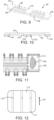
- FIG. 8 shows another version of a wear pad.
- the wear pad 80 has depending guides 82 at each side flanking a wear surface 84 riding along a wearstrip 86.
- the guides 82 limit lateral wander of the conveyor belt to the width of the slot 88 formed between the two depending guides 82.
- the guides 82 provide belt tracking.
- FIG. 9 Another version of a conveyor belt module is shown in FIG. 9 .
- the belt module 90 has outer wear pads 92 and an inner wear pad 93 whose wear surfaces 94 are at a different level from the bottoms of the drive bar 96 and the hinge elements 98, which define the bottom-most level of the module. Otherwise the module 90 is like the belt module 20 of FIGS. 1 and 2 . Because the wear surfaces 94 of the wear pads 92, 93 are indented upward from the bottom-most level 100 of the module 90 as shown in FIG. 10 , a conveyor belt constructed of the modules 90 forms a longitudinal slot 102 in which wear strips 104 are received. The downward extension of the drive bars 96 and the hinge elements 98' bounding the wear pads 92, 93 past their indented wear surfaces 94 limits lateral wander of the conveyor belt by contact with the sides of the wear strips 104.
- FIGS. 11 and 12 show two examples of wear indicators built into wear pads.
- a wear pad 106 has an internal layer 108 of a different color than the original outer wear surface 110.
- the internal layer of a different color becomes visible to indicate wear of the wear pad 106.
- a wear surface 112 is interrupted by grooves 114 that are elongated in the direction of belt travel 54. Slightly raised portions 116 of the base of the grooves serve as wear indicators like those in tire treads.
- the wear surface 112 wears, the distance from the top of the wear indicators 116 to the worn wear surface decreases so that wear can be identified, and corrective action taken.
- FIGS. 13A and 13B Another version of a belt module with a different outside edge is shown in FIGS. 13A and 13B .
- the module 120 is shown as an edge module with a wear pad 122 at an outer side 124 and suitable for constructing a bricklaid conveyor belt. But a wider module with a similar outer side at the other side, with or without interior wear pads, could be made for constructing non-bricklaid belts having a single module forming each belt row.
- the module 120 has first and second hinge elements 28, 29 and a drive bar 38 like the module of FIG. 2 .
- the wear pad 122 has a slot 128 extending at an angle from the wear pad's wear surface 126 along an inner wall 129 of the wear pad for a rod-removal tool, such as a screwdriver, to access the end of a hinge rod and bend it away from a stop formed by the inner wall and toward the level of the wear surface so that the rod can be removed from the hinge elements.
- a rod-removal tool such as a screwdriver
- a belt module 130 with another version of a wear pad 132 at an outer side 134 is shown in FIGS. 14A and 14B .
- the wear pad's wear surface at the bottom of the module 130 has a lateral extent and an area greater than those of first and second hinge elements 28, 29.
- the wear pad 132 tapers away from the wear surface 136 along a ramp 138 in line with and facing the aligned first hinge elements 28.
- the ramp 138 is shown as concavely curved, but could also be flat.
- the ramp 138 provides a slide surface along which the end of a hinge rod can slide when the rod is pushed out through the hinge elements during manual removal.
- the belt module 130 can be a narrow edge module as shown or it can be a wider module with similar wear pads 132 at both outer sides.
Landscapes
- Engineering & Computer Science (AREA)
- Mechanical Engineering (AREA)
- Chain Conveyers (AREA)
- Belt Conveyors (AREA)
Claims (13)
- Förderbandmodul (20; 90; 120; 130), das Folgendes umfasst:einen Modulkörper (20; 68; 76), der sich in der Länge von einem ersten Ende (22) zu einem zweiten Ende (23), in der Breite von einer ersten Seite (24) zu einer zweiten Seite (25) und in der Dicke von einer Oberseite (26) zu einer Unterseite (27) erstreckt;mehrere erste Scharnierelemente (28), die seitlich entlang des ersten Endes (22) des Modulkörpers (20; 68; 76) voneinander beabstandet sind;mehrere zweite Scharnierelemente (29), die seitlich entlang des zweiten Endes (23) des Modulkörpers (20; 68; 76) voneinander beabstandet sind;Antriebsflächen (40, 41), die sich seitlich entlang der Unterseite (27) des Modulkörpers (20; 68; 76) erstrecken; und wobei das Modul (20; 68; 76) Folgendes umfasst:a) einen oder mehrere Verschleißblöcke (30, 32; 64; 80; 92, 93; 106; 122; 132) auf der Unterseite (27) des Modulkörpers (20; 68; 76), die seitlich von den Antriebsflächen (40, 41) und von den ersten und zweiten Scharnierelementen (28, 29) versetzt sind; undwobei die Verschleißblöcke (30, 32; 64; 80; 92, 93; 106; 122; 132) jeweils eine Verschleißfläche (34; 66; 70; 84; 94; 110; 112; 126; 136) an der Unterseite (27) aufweisen;wobei der Flächeninhalt der Verschleißfläche (34; 66; 70; 84; 94; 110; 112; 126; 136) jedes der Verschleißblöcke (30, 32; 64; 80; 92, 93; 106; 122; 132) größer ist als der Flächeninhalt der ersten und zweiten Scharnierelemente (28, 29) an der Unterseite (27); undwobei mindestens einer der Verschleißblöcke (32) ein Blockscharnierelement (36) umfasst, das mit den ersten Scharnierelementen (28) am ersten Ende (22) des Modulkörpers (20; 68; 76) ausgerichtet ist, das eine Fortsetzung der Verschleißfläche (33; 66; 70; 84; 94; 110; 112; 126; 136) des Verschleißblocks (30, 32; 64; 80 ; 92, 93; 106; 122; 132) bildet und dessen seitliche Ausdehnung mindestens so breit ist wie die seitliche Ausdehnung des Verschleißblocks (30, 32; 64; 80; 92, 93; 106; 122; 132); oderb) wobei das Modul mehrere Verschleißblöcke (64) auf der Unterseite des Modulkörpers umfasst, die seitlich von den Antriebsflächen und von den ersten und zweiten Scharnierelementen versetzt sind;wobei die Verschleißblöcke (64) jeweils eine Verschleißfläche auf der Unterseite aufweisen, die aus einem anderen Material besteht als der Rest des Modulkörpers (68); undwobei mindestens einer der Verschleißblöcke (64) ein Blockscharnierelement umfasst, das mit den ersten Scharnierelementen am ersten Ende des Modulkörpers ausgerichtet ist, das eine Fortsetzung der Verschleißfläche des Verschleißblocks bildet und dessen seitliche Ausdehnung mindestens so breit ist wie die seitliche Ausdehnung des Verschleißblocks (64).
- Förderbandmodul nach Anspruch 1, wobei die ein oder mehreren Verschleißblöcke einen ersten festen Verschleißblock an der ersten Seite des Modulkörpers und einen zweiten festen Verschleißblock an der zweiten Seite des Modulkörpers umfassen, oder wobei die ein oder mehreren Verschleißblöcke vom Modulkörper (76) abnehmbar sind.
- Förderbandmodul nach Anspruch 1, wobei die Antriebsflächen an seitlich verlängerten Antriebsstäben (38) ausgebildet sind, die sich bis zur Höhe der Verschleißflächen (34) an der Unterseite des Modulkörpers erstrecken; oder wobei die Antriebsflächen an verlängerten Antriebsstäben (38) ausgebildet sind, die sich seitlich von einem der Verschleißblöcke (30) zu einem anderen der Verschleißblöcke (32) erstrecken.
- Förderbandmodul nach Anspruch 1, wobei ein Teil der Verschleißblöcke (106), der die Verschleißfläche (110; 112) aufweist, einen Verschleißanzeiger umfasst, der den Verschleiß der Verschleißfläche anzeigt.
- Förderbandmodul nach Anspruch 4, wobei die Verschleißfläche (112) eine oder mehrere Nuten (114) aufweist und der Verschleißanzeiger einen erhabenen Teil (116) der Basis der Nuten (114) umfasst; oder wobei der Verschleißanzeiger eine Schicht (108) des Verschleißblockinneren der Verschleißfläche (110) umfasst, die sich in der Farbe von der unverschlissenen Verschleißfläche (110) unterscheidet.
- Förderbandmodul nach Anspruch 1, wobeia) die Verschleißfläche (34) der Verschleißblöcke (30, 32) eine geschlossene Fläche ist; oderb) die Verschleißflächen (34) der Verschleißblöcke die unterste Ebene der Unterseite des Modulkörpers definieren; oderc) wobei die Verschleißflächen (94) der Verschleißblöcke von der untersten Ebene (100) der Unterseite des Modulkörpers nach oben eingedrückt sind.
- Förderbandmodul nach Anspruch 1, wobei einer der Verschleißblöcke die erste Seite des Förderbandmoduls bildet, und wobei a) der die erste Seite des Förderbandmoduls bildende Verschleißblock (122) eine Innenwand (129) aufweist, die einen Anschlag in einer Linie mit den ersten Scharnierelementen (28) und diesen zugewandt bildet; oder b) wobei der die erste Seite des Förderbandmoduls bildende Verschleißblock (132) eine Rampe (138) in einer Linie mit den ersten Scharnierelementen (28) und diesen zugewandt bildet, die sich zur Verschleißfläche des Verschleißblocks erstreckt.
- Förderbandmodul nach Anspruch 1, wobei die seitliche Ausdehnung der Verschleißfläche jedes der Verschleißblöcke (122) größer ist als die seitliche Ausdehnung eines der ersten und zweiten Scharnierelemente (28, 29) an der Unterseite.
- Modulares Förderband (56), das mehrere Förderbandmodule (20) wie in Anspruch 1 beansprucht umfasst, die in einer Serie von Reihen von einem oder mehreren der Förderbandmodule angeordnet sind, wobei die Reihen an den ineinandergreifenden ersten und zweiten Scharnierelementen (28, 29) der Förderbandmodule (20) aufeinanderfolgender Reihen zu einer Endlosschleife miteinander verbunden sind.
- Förderer (55), der Folgendes umfasst:ein modulares Förderband (56), das eine Serie von Reihen aus einem oder mehreren Bandmodulen (20) umfasst, die an Scharnierverbindungen (46) zwischen aufeinanderfolgenden Reihen gelenkig Ende an Ende verbunden sind;wobei mindestens einige der Reihen Folgendes beinhalten:erste Scharnierelemente (28), die entlang erster Enden der Reihe beabstandet sind, und zweite Scharnierelemente (29), die entlang gegenüberliegender zweiter Enden der Reihe beabstandet sind;Scharnierstäbe, die sich durch die ineinandergreifenden ersten und zweiten Scharnierelemente (28, 29) aufeinanderfolgender Reihen erstrecken, um aufeinanderfolgende Reihen an den Scharniergelenken (46) miteinander zu verbinden;Antriebsflächen (40, 41), die sich seitlich entlang einer Unterseite des modularen Förderbandes (56) erstrecken;mehrere Verschleißblöcke (30, 32) auf der Unterseite des modularen Förderbandes (56), die seitlich von den Antriebsflächen (40, 41) und von den ersten und zweiten Scharnierelementen (28, 29) versetzt sind;wobei die Verschleißblöcke (30, 32) jeweils eine Verschleißfläche (34) auf der Unterseite des modularen Förderbandes (56) aufweisen;wobei mindestens einer der Verschleißblöcke (32) ein Blockscharnierelement (36) umfasst, das mit den ersten Scharnierelementen (28) am ersten Ende des Modulkörpers ausgerichtet ist, das eine Fortsetzung der Verschleißfläche des Verschleißblocks (32) bildet und dessen seitliche Ausdehnung mindestens so breit ist wie die seitliche Ausdehnung des Verschleißblocks;einen oberen Transportweg (50) mit mehreren Verschleißstreifen (52), die über die Breite des Transportwegs (50) verteilt sind und sich linear entlang der Länge des Transportwegs (50) erstrecken, um das modulare Förderband (56) zu tragen;ein Antriebselement, das mit den Antriebsflächen (40, 41) in Eingriff steht, um das modulare Förderband (56) in einer Bandlaufrichtung (54) entlang des Transportwegs (50) anzutreiben;wobei die Verschleißblöcke (32) auf der Unterseite des modularen Förderbandes (56) in Spalten angeordnet sind, die mit den Verschleißstreifen (52) ausgerichtet sind, so dass die Verschleißflächen (34) auf den Verschleißstreifen (52) laufen, wenn das modulare Förderband (56) in der Bandlaufrichtung (54) angetrieben wird.
- Förderband nach Anspruch 10, wobei mindestens einige der Reihen auf der Unterseite neben den Antriebsflächen (40, 41) vertiefte Regionen (42) zum Aufnehmen der Zähne von Kettenrädern (58, 59) aufweisen, wobei die vertieften Regionen (42) durch Endwände (43) an den Seiten der Verschleißblöcke begrenzt sind, um ein seitliches Wandern des modularen Förderbandes relativ zu einem axial fixierten Kettenrad zu begrenzen.
- Förderer nach Anspruch 10, wobei jede Reihe von Bandmodulen Verschleißblöcke aufweist, die Außenseiten des Förderbandes bilden.
- Förderbandmodul nach Anspruch 12, wobeia) die Verschleißblöcke, die die Außenseiten des Förderbandes bilden, jeweils eine Rampe (138) in einer Linie mit den ineinandergreifenden ersten und zweiten Scharnierelementen und diesen zugewandt aufweisen, die sich bis zur Verschleißfläche des Verschleißblocks erstreckt, um eine Gleitfläche bereitzustellen, entlang derer der Scharnierstab während des Entfernens aus dem Scharniergelenk verschoben werden kann; oderb) die Verschleißblöcke, die die Außenseiten des Förderbandes bilden, jeweils eine Innenwand (129) aufweisen, die einen Anschlag in einer Linie mit und gegenüber den ineinandergreifenden ersten und zweiten Scharnierelementen bildet, um zu verhindern, dass sich der Scharnierstab, der die ineinandergreifenden ersten und zweiten Scharnierelemente verbindet, während des Betriebs des Förderers aus dem Scharniergelenk herausarbeitet; oderc) die Verschleißblöcke, die die Außenseiten des Förderbandes bilden, jeweils eine Innenwand (129) aufweisen, die einen Anschlag in einer Linie mit und gegenüber den ineinandergreifenden ersten und zweiten Scharnierelementen bildet, um zu verhindern, dass sich der Scharnierstab, der die ineinandergreifenden ersten und zweiten Scharnierelemente verbindet, während des Betriebs des Förderers aus dem Scharniergelenk herausarbeitet, undwobei die die Außenseiten des Förderbandes bildenden Verschleißblöcke jeweils einen Schlitz (128) aufweisen, der sich von der Verschleißfläche des Verschleißblocks entlang der Innenwand erstreckt, damit ein Entfernungswerkzeug auf den Scharnierstab zugreifen kann.
Applications Claiming Priority (2)
| Application Number | Priority Date | Filing Date | Title |
|---|---|---|---|
| US201962837819P | 2019-04-24 | 2019-04-24 | |
| PCT/US2020/026674 WO2020219254A1 (en) | 2019-04-24 | 2020-04-03 | Conveyor belt and module with wear pads |
Publications (3)
| Publication Number | Publication Date |
|---|---|
| EP3959159A1 EP3959159A1 (de) | 2022-03-02 |
| EP3959159A4 EP3959159A4 (de) | 2023-01-25 |
| EP3959159B1 true EP3959159B1 (de) | 2025-06-04 |
Family
ID=72941299
Family Applications (1)
| Application Number | Title | Priority Date | Filing Date |
|---|---|---|---|
| EP20796002.2A Active EP3959159B1 (de) | 2019-04-24 | 2020-04-03 | Förderband und modul mit verschleisskissen |
Country Status (5)
| Country | Link |
|---|---|
| US (3) | US11807461B2 (de) |
| EP (1) | EP3959159B1 (de) |
| CN (1) | CN113646244B (de) |
| DK (1) | DK3959159T3 (de) |
| WO (1) | WO2020219254A1 (de) |
Families Citing this family (2)
| Publication number | Priority date | Publication date | Assignee | Title |
|---|---|---|---|---|
| BR112022013142A2 (pt) | 2020-01-06 | 2022-09-06 | Laitram Llc | Montagem de acesso exclusivo para uma correia transportadora |
| WO2025265080A1 (en) * | 2024-06-20 | 2025-12-26 | Safari Belting Systems, Inc. | Conveyor module with elevatable outside edge |
Family Cites Families (32)
| Publication number | Priority date | Publication date | Assignee | Title |
|---|---|---|---|---|
| US4832187A (en) | 1980-08-19 | 1989-05-23 | The Laitram Corporation | Modular center drive conveyor belt |
| US4974724A (en) | 1987-10-06 | 1990-12-04 | The Laitram Corporation | Conveyor belt with a connecting member drive |
| US4971191A (en) | 1987-10-06 | 1990-11-20 | The Laitram Corporation | Accurate tracking center driven open area belt |
| US4925016A (en) | 1987-10-06 | 1990-05-15 | The Laitram Corporation | Heavy duty modular conveyor belt and sprocket with unique tracking |
| US4934517A (en) | 1988-11-14 | 1990-06-19 | The Laitram Corporation | Horizontal flexing conveyor belt |
| US4949838A (en) | 1988-11-14 | 1990-08-21 | The Laitram Corporation | Apparatus and methods to allow non-destructive removal of pivot rods in modular plastic conveyor belts |
| US4953693A (en) | 1989-01-23 | 1990-09-04 | Span Tech Corporation | Modular link conveyor system |
| US5105938A (en) | 1991-06-14 | 1992-04-21 | The Laitram Corporation | Pivot rod retention structure in modular conveyor belts |
| US5377819A (en) * | 1993-07-02 | 1995-01-03 | The Laitram Corporation | Conveyor apparatus and method |
| US5361893A (en) | 1993-11-18 | 1994-11-08 | The Laitram Corporation | High friction plastic conveyor belts having modular links formed by two integrated plastic materials |
| US5372248A (en) | 1994-01-18 | 1994-12-13 | The Laitram Corporation | Radius conveyor belt |
| US5850902A (en) | 1995-10-06 | 1998-12-22 | The Laitram Corporation | Transferring articles from a moving belt edge onto a normally disposed moving conveyor belt |
| US5921379A (en) | 1996-01-23 | 1999-07-13 | The Laitram Corporation | Modular conveyor belt suitable for following straight or curved paths |
| US6345715B2 (en) | 1998-11-03 | 2002-02-12 | Kvp Falcon Plastic Belting, Inc. | Rod retention system for modular plastic conveyor belt |
| EP1126477A3 (de) | 2000-02-14 | 2003-06-18 | Leica Microsystems Lithography GmbH | Verfahren zur Untersuchung von Strukturen auf einem Halbleiter-Substrat |
| DE10027229A1 (de) * | 2000-05-31 | 2001-12-06 | Flexon Systemplast Gmbh | Förderkette mit Kettengliedern aus mindestens zwei unterschiedlichen Materialien |
| US6644466B2 (en) | 2002-01-31 | 2003-11-11 | The Laitram Corporation | Platform-top radius belt and modules |
| US6814223B1 (en) | 2003-09-25 | 2004-11-09 | Laitram, L.L.C. | Self-closing hinge rod retention in modular plastic conveyor belts |
| US7073662B2 (en) | 2004-02-20 | 2006-07-11 | Ashworth Bros., Inc. | Conveyor belt and method of assembly |
| JP5184099B2 (ja) | 2005-02-24 | 2013-04-17 | レイトラム リミテッド ライアビリティー カンパニー | ベルトモジュール |
| US7980385B2 (en) | 2005-06-14 | 2011-07-19 | Laitram, L.L.C. | Plastic conveyor belts and modules with lateral channels |
| US8464862B2 (en) | 2006-01-31 | 2013-06-18 | Thermodrive, Llc | Conveyor with troughed low friction, positive drive belt |
| PL1981784T3 (pl) | 2006-02-08 | 2014-09-30 | Thermodrive Llc | Przenośnik krzywoliniowy z prowadnicą do zapobiegania promieniowemu przemieszczaniu się taśmy |
| EP2222578B1 (de) * | 2007-12-27 | 2016-08-17 | Laitram, LLC | Modul für ein modulares förderband |
| US8579104B2 (en) | 2010-05-13 | 2013-11-12 | Laitram, L.L.C. | Conveyor belt and module accommodating rod growth |
| CH704134A1 (de) | 2010-11-26 | 2012-05-31 | Ferag Ag | Fördersystem, förderelement und führungskanal. |
| US8863944B2 (en) * | 2012-02-20 | 2014-10-21 | Laitram, L.L.C. | Abrasion resistant conveyor belt |
| MX2015004619A (es) * | 2012-10-25 | 2016-01-12 | Solus Ind Innovations Llc | Dispositivos y metodos de indicación de desgaste del sistema de banda transportadora. |
| US20160200520A1 (en) * | 2013-08-27 | 2016-07-14 | Rexnord Flattop Europe B.V. | Conveyor module, conveyor mat or chain, method for monitoring wear of a conveyor element, and conveyor system |
| US9254964B2 (en) | 2014-04-16 | 2016-02-09 | Laitram, L.L.C. | Textured-top conveyor belt module |
| US9663298B2 (en) * | 2014-12-18 | 2017-05-30 | Laitram, L.L.C. | Conveyor belt module with shaped bottom surface |
| EP3341309A4 (de) | 2015-10-08 | 2019-04-17 | Laitram, L.L.C. | Förderband mit längsschienen |
-
2020
- 2020-04-03 WO PCT/US2020/026674 patent/WO2020219254A1/en not_active Ceased
- 2020-04-03 CN CN202080023046.9A patent/CN113646244B/zh active Active
- 2020-04-03 US US17/601,895 patent/US11807461B2/en active Active
- 2020-04-03 DK DK20796002.2T patent/DK3959159T3/da active
- 2020-04-03 US US17/601,893 patent/US11772897B2/en active Active
- 2020-04-03 EP EP20796002.2A patent/EP3959159B1/de active Active
-
2023
- 2023-09-26 US US18/373,084 patent/US12145804B2/en active Active
Also Published As
| Publication number | Publication date |
|---|---|
| CN113646244B (zh) | 2023-08-29 |
| US11772897B2 (en) | 2023-10-03 |
| US20220212874A1 (en) | 2022-07-07 |
| US20240025652A1 (en) | 2024-01-25 |
| CN113646244A (zh) | 2021-11-12 |
| US11807461B2 (en) | 2023-11-07 |
| WO2020219254A1 (en) | 2020-10-29 |
| DK3959159T3 (da) | 2025-06-16 |
| EP3959159A1 (de) | 2022-03-02 |
| US20220204276A1 (en) | 2022-06-30 |
| EP3959159A4 (de) | 2023-01-25 |
| US12145804B2 (en) | 2024-11-19 |
Similar Documents
| Publication | Publication Date | Title |
|---|---|---|
| EP0631950B1 (de) | Fördervorrichtung | |
| JP5744948B2 (ja) | トラフ形の低摩擦ポジティブドライブベルトを備えるコンベヤ | |
| US4865183A (en) | Wide chain conveyor sprocket drive | |
| US7810637B2 (en) | Positively driven, tracking flat belt and conveyor | |
| EP1585692B1 (de) | Flexibles mitnehmermodul für modulare kunststoff-förderbänder | |
| US12145804B2 (en) | Conveyor belt module with wear pads | |
| CA2340288C (en) | Radius conveyor belt | |
| EP1687221B1 (de) | Kunststoffförderbandmodule mit seitenschutz | |
| CA2140419C (en) | Radius conveyor belt | |
| EP0459691A1 (de) | Modulfördergurt | |
| US6644466B2 (en) | Platform-top radius belt and modules | |
| US4351429A (en) | Conveyor with slip cleats | |
| US6079543A (en) | Lane-divided plastic conveyor belt | |
| US7097030B2 (en) | Long, flexible conveyor belt modules in modular plastic conveyor belts | |
| WO2004054900A2 (en) | Flexible conveyor belt with easily replaceable and adjustable flight and lane dividers | |
| EP0333309A1 (de) | Breiter Kettenförderer | |
| EP1174371B1 (de) | Förderband mit modularem Radius | |
| EP1890950B1 (de) | Kunststoffförderbänder und module mit seitenkanälen | |
| US10273088B2 (en) | Conveyor belt with longitudinal rails |
Legal Events
| Date | Code | Title | Description |
|---|---|---|---|
| STAA | Information on the status of an ep patent application or granted ep patent |
Free format text: STATUS: THE INTERNATIONAL PUBLICATION HAS BEEN MADE |
|
| PUAI | Public reference made under article 153(3) epc to a published international application that has entered the european phase |
Free format text: ORIGINAL CODE: 0009012 |
|
| STAA | Information on the status of an ep patent application or granted ep patent |
Free format text: STATUS: REQUEST FOR EXAMINATION WAS MADE |
|
| 17P | Request for examination filed |
Effective date: 20210929 |
|
| AK | Designated contracting states |
Kind code of ref document: A1 Designated state(s): AL AT BE BG CH CY CZ DE DK EE ES FI FR GB GR HR HU IE IS IT LI LT LU LV MC MK MT NL NO PL PT RO RS SE SI SK SM TR |
|
| DAV | Request for validation of the european patent (deleted) | ||
| DAX | Request for extension of the european patent (deleted) | ||
| A4 | Supplementary search report drawn up and despatched |
Effective date: 20221223 |
|
| RIC1 | Information provided on ipc code assigned before grant |
Ipc: B65G 17/08 20060101ALI20221219BHEP Ipc: B65G 17/40 20060101AFI20221219BHEP |
|
| GRAP | Despatch of communication of intention to grant a patent |
Free format text: ORIGINAL CODE: EPIDOSNIGR1 |
|
| STAA | Information on the status of an ep patent application or granted ep patent |
Free format text: STATUS: GRANT OF PATENT IS INTENDED |
|
| INTG | Intention to grant announced |
Effective date: 20250115 |
|
| P01 | Opt-out of the competence of the unified patent court (upc) registered |
Free format text: CASE NUMBER: APP_13669/2025 Effective date: 20250319 |
|
| GRAS | Grant fee paid |
Free format text: ORIGINAL CODE: EPIDOSNIGR3 |
|
| GRAA | (expected) grant |
Free format text: ORIGINAL CODE: 0009210 |
|
| STAA | Information on the status of an ep patent application or granted ep patent |
Free format text: STATUS: THE PATENT HAS BEEN GRANTED |
|
| AK | Designated contracting states |
Kind code of ref document: B1 Designated state(s): AL AT BE BG CH CY CZ DE DK EE ES FI FR GB GR HR HU IE IS IT LI LT LU LV MC MK MT NL NO PL PT RO RS SE SI SK SM TR |
|
| REG | Reference to a national code |
Ref country code: GB Ref legal event code: FG4D |
|
| RIN1 | Information on inventor provided before grant (corrected) |
Inventor name: BISHOP, CATHERINE M. Inventor name: BOGLE, DAVID W. Inventor name: GUERNSEY, KEVIN W. |
|
| REG | Reference to a national code |
Ref country code: CH Ref legal event code: EP |
|
| REG | Reference to a national code |
Ref country code: DK Ref legal event code: T3 Effective date: 20250613 |
|
| REG | Reference to a national code |
Ref country code: DE Ref legal event code: R096 Ref document number: 602020052362 Country of ref document: DE |
|
| REG | Reference to a national code |
Ref country code: NL Ref legal event code: FP Ref country code: IE Ref legal event code: FG4D |
|
| PG25 | Lapsed in a contracting state [announced via postgrant information from national office to epo] |
Ref country code: FI Free format text: LAPSE BECAUSE OF FAILURE TO SUBMIT A TRANSLATION OF THE DESCRIPTION OR TO PAY THE FEE WITHIN THE PRESCRIBED TIME-LIMIT Effective date: 20250604 Ref country code: ES Free format text: LAPSE BECAUSE OF FAILURE TO SUBMIT A TRANSLATION OF THE DESCRIPTION OR TO PAY THE FEE WITHIN THE PRESCRIBED TIME-LIMIT Effective date: 20250604 |
|
| REG | Reference to a national code |
Ref country code: LT Ref legal event code: MG9D |
|
| PG25 | Lapsed in a contracting state [announced via postgrant information from national office to epo] |
Ref country code: NO Free format text: LAPSE BECAUSE OF FAILURE TO SUBMIT A TRANSLATION OF THE DESCRIPTION OR TO PAY THE FEE WITHIN THE PRESCRIBED TIME-LIMIT Effective date: 20250904 Ref country code: GR Free format text: LAPSE BECAUSE OF FAILURE TO SUBMIT A TRANSLATION OF THE DESCRIPTION OR TO PAY THE FEE WITHIN THE PRESCRIBED TIME-LIMIT Effective date: 20250905 |
|
| PG25 | Lapsed in a contracting state [announced via postgrant information from national office to epo] |
Ref country code: PL Free format text: LAPSE BECAUSE OF FAILURE TO SUBMIT A TRANSLATION OF THE DESCRIPTION OR TO PAY THE FEE WITHIN THE PRESCRIBED TIME-LIMIT Effective date: 20250604 |
|
| PG25 | Lapsed in a contracting state [announced via postgrant information from national office to epo] |
Ref country code: BG Free format text: LAPSE BECAUSE OF FAILURE TO SUBMIT A TRANSLATION OF THE DESCRIPTION OR TO PAY THE FEE WITHIN THE PRESCRIBED TIME-LIMIT Effective date: 20250604 |
|
| PG25 | Lapsed in a contracting state [announced via postgrant information from national office to epo] |
Ref country code: HR Free format text: LAPSE BECAUSE OF FAILURE TO SUBMIT A TRANSLATION OF THE DESCRIPTION OR TO PAY THE FEE WITHIN THE PRESCRIBED TIME-LIMIT Effective date: 20250604 |
|
| PG25 | Lapsed in a contracting state [announced via postgrant information from national office to epo] |
Ref country code: RS Free format text: LAPSE BECAUSE OF FAILURE TO SUBMIT A TRANSLATION OF THE DESCRIPTION OR TO PAY THE FEE WITHIN THE PRESCRIBED TIME-LIMIT Effective date: 20250904 |
|
| PG25 | Lapsed in a contracting state [announced via postgrant information from national office to epo] |
Ref country code: LV Free format text: LAPSE BECAUSE OF FAILURE TO SUBMIT A TRANSLATION OF THE DESCRIPTION OR TO PAY THE FEE WITHIN THE PRESCRIBED TIME-LIMIT Effective date: 20250604 |
|
| PG25 | Lapsed in a contracting state [announced via postgrant information from national office to epo] |
Ref country code: PT Free format text: LAPSE BECAUSE OF FAILURE TO SUBMIT A TRANSLATION OF THE DESCRIPTION OR TO PAY THE FEE WITHIN THE PRESCRIBED TIME-LIMIT Effective date: 20251006 |
|
| REG | Reference to a national code |
Ref country code: AT Ref legal event code: MK05 Ref document number: 1800186 Country of ref document: AT Kind code of ref document: T Effective date: 20250604 |
|
| PG25 | Lapsed in a contracting state [announced via postgrant information from national office to epo] |
Ref country code: IS Free format text: LAPSE BECAUSE OF FAILURE TO SUBMIT A TRANSLATION OF THE DESCRIPTION OR TO PAY THE FEE WITHIN THE PRESCRIBED TIME-LIMIT Effective date: 20251004 |
|
| PG25 | Lapsed in a contracting state [announced via postgrant information from national office to epo] |
Ref country code: AT Free format text: LAPSE BECAUSE OF FAILURE TO SUBMIT A TRANSLATION OF THE DESCRIPTION OR TO PAY THE FEE WITHIN THE PRESCRIBED TIME-LIMIT Effective date: 20250604 Ref country code: SM Free format text: LAPSE BECAUSE OF FAILURE TO SUBMIT A TRANSLATION OF THE DESCRIPTION OR TO PAY THE FEE WITHIN THE PRESCRIBED TIME-LIMIT Effective date: 20250604 |
|
| PG25 | Lapsed in a contracting state [announced via postgrant information from national office to epo] |
Ref country code: CZ Free format text: LAPSE BECAUSE OF FAILURE TO SUBMIT A TRANSLATION OF THE DESCRIPTION OR TO PAY THE FEE WITHIN THE PRESCRIBED TIME-LIMIT Effective date: 20250604 |
|
| PG25 | Lapsed in a contracting state [announced via postgrant information from national office to epo] |
Ref country code: EE Free format text: LAPSE BECAUSE OF FAILURE TO SUBMIT A TRANSLATION OF THE DESCRIPTION OR TO PAY THE FEE WITHIN THE PRESCRIBED TIME-LIMIT Effective date: 20250604 |
|
| PG25 | Lapsed in a contracting state [announced via postgrant information from national office to epo] |
Ref country code: SK Free format text: LAPSE BECAUSE OF FAILURE TO SUBMIT A TRANSLATION OF THE DESCRIPTION OR TO PAY THE FEE WITHIN THE PRESCRIBED TIME-LIMIT Effective date: 20250604 Ref country code: RO Free format text: LAPSE BECAUSE OF FAILURE TO SUBMIT A TRANSLATION OF THE DESCRIPTION OR TO PAY THE FEE WITHIN THE PRESCRIBED TIME-LIMIT Effective date: 20250604 |
|
| PG25 | Lapsed in a contracting state [announced via postgrant information from national office to epo] |
Ref country code: IT Free format text: LAPSE BECAUSE OF FAILURE TO SUBMIT A TRANSLATION OF THE DESCRIPTION OR TO PAY THE FEE WITHIN THE PRESCRIBED TIME-LIMIT Effective date: 20250604 |
|
| REG | Reference to a national code |
Ref country code: DE Ref legal event code: R097 Ref document number: 602020052362 Country of ref document: DE |
|
| PLBE | No opposition filed within time limit |
Free format text: ORIGINAL CODE: 0009261 |
|
| STAA | Information on the status of an ep patent application or granted ep patent |
Free format text: STATUS: NO OPPOSITION FILED WITHIN TIME LIMIT |
|
| PGFP | Annual fee paid to national office [announced via postgrant information from national office to epo] |
Ref country code: DK Payment date: 20260330 Year of fee payment: 7 |
|
| PGFP | Annual fee paid to national office [announced via postgrant information from national office to epo] |
Ref country code: NL Payment date: 20260323 Year of fee payment: 7 |
|
| REG | Reference to a national code |
Ref country code: CH Ref legal event code: L10 Free format text: ST27 STATUS EVENT CODE: U-0-0-L10-L00 (AS PROVIDED BY THE NATIONAL OFFICE) Effective date: 20260416 |