EP3960027A2 - Dispositif d'accoudoir - Google Patents
Dispositif d'accoudoir Download PDFInfo
- Publication number
- EP3960027A2 EP3960027A2 EP20793988.5A EP20793988A EP3960027A2 EP 3960027 A2 EP3960027 A2 EP 3960027A2 EP 20793988 A EP20793988 A EP 20793988A EP 3960027 A2 EP3960027 A2 EP 3960027A2
- Authority
- EP
- European Patent Office
- Prior art keywords
- link
- rotary shaft
- arm
- fixed
- arm rest
- Prior art date
- Legal status (The legal status is an assumption and is not a legal conclusion. Google has not performed a legal analysis and makes no representation as to the accuracy of the status listed.)
- Pending
Links
Images




Classifications
-
- A—HUMAN NECESSITIES
- A47—FURNITURE; DOMESTIC ARTICLES OR APPLIANCES; COFFEE MILLS; SPICE MILLS; SUCTION CLEANERS IN GENERAL
- A47B—TABLES; DESKS; OFFICE FURNITURE; CABINETS; DRAWERS; GENERAL DETAILS OF FURNITURE
- A47B21/00—Tables or desks for office equipment, e.g. typewriters, keyboards
- A47B21/03—Tables or desks for office equipment, e.g. typewriters, keyboards with substantially horizontally extensible or adjustable parts other than drawers, e.g. leaves
- A47B21/0371—Platforms for supporting wrists
-
- A—HUMAN NECESSITIES
- A47—FURNITURE; DOMESTIC ARTICLES OR APPLIANCES; COFFEE MILLS; SPICE MILLS; SUCTION CLEANERS IN GENERAL
- A47C—CHAIRS; SOFAS; BEDS
- A47C16/00—Stand-alone rests or supports for feet, legs, arms, back or head
-
- A—HUMAN NECESSITIES
- A47—FURNITURE; DOMESTIC ARTICLES OR APPLIANCES; COFFEE MILLS; SPICE MILLS; SUCTION CLEANERS IN GENERAL
- A47C—CHAIRS; SOFAS; BEDS
- A47C20/00—Head-, foot- or like rests for beds, sofas or the like
- A47C20/02—Head-, foot- or like rests for beds, sofas or the like of detachable type
- A47C20/023—Arm supports
-
- A—HUMAN NECESSITIES
- A47—FURNITURE; DOMESTIC ARTICLES OR APPLIANCES; COFFEE MILLS; SPICE MILLS; SUCTION CLEANERS IN GENERAL
- A47C—CHAIRS; SOFAS; BEDS
- A47C7/00—Parts, details, or accessories of chairs or stools
- A47C7/54—Supports for the arms
- A47C7/541—Supports for the arms of adjustable type
-
- A—HUMAN NECESSITIES
- A47—FURNITURE; DOMESTIC ARTICLES OR APPLIANCES; COFFEE MILLS; SPICE MILLS; SUCTION CLEANERS IN GENERAL
- A47C—CHAIRS; SOFAS; BEDS
- A47C7/00—Parts, details, or accessories of chairs or stools
- A47C7/54—Supports for the arms
- A47C7/546—Supports for the arms of detachable type
-
- A—HUMAN NECESSITIES
- A61—MEDICAL OR VETERINARY SCIENCE; HYGIENE
- A61B—DIAGNOSIS; SURGERY; IDENTIFICATION
- A61B90/00—Instruments, implements or accessories specially adapted for surgery or diagnosis and not covered by any of the groups A61B1/00 - A61B50/00, e.g. for luxation treatment or for protecting wound edges
- A61B90/60—Supports for surgeons, e.g. chairs or hand supports
-
- B—PERFORMING OPERATIONS; TRANSPORTING
- B25—HAND TOOLS; PORTABLE POWER-DRIVEN TOOLS; MANIPULATORS
- B25J—MANIPULATORS; CHAMBERS PROVIDED WITH MANIPULATION DEVICES
- B25J13/00—Controls for manipulators
- B25J13/02—Hand grip control means
-
- B—PERFORMING OPERATIONS; TRANSPORTING
- B25—HAND TOOLS; PORTABLE POWER-DRIVEN TOOLS; MANIPULATORS
- B25J—MANIPULATORS; CHAMBERS PROVIDED WITH MANIPULATION DEVICES
- B25J17/00—Joints
- B25J17/02—Wrist joints
- B25J17/0258—Two-dimensional joints
- B25J17/0266—Two-dimensional joints comprising more than two actuating or connecting rods
-
- B—PERFORMING OPERATIONS; TRANSPORTING
- B25—HAND TOOLS; PORTABLE POWER-DRIVEN TOOLS; MANIPULATORS
- B25J—MANIPULATORS; CHAMBERS PROVIDED WITH MANIPULATION DEVICES
- B25J9/00—Program-controlled manipulators
- B25J9/0006—Exoskeletons, i.e. resembling a human figure
-
- B—PERFORMING OPERATIONS; TRANSPORTING
- B25—HAND TOOLS; PORTABLE POWER-DRIVEN TOOLS; MANIPULATORS
- B25J—MANIPULATORS; CHAMBERS PROVIDED WITH MANIPULATION DEVICES
- B25J9/00—Program-controlled manipulators
- B25J9/10—Program-controlled manipulators characterised by positioning means for manipulator elements
- B25J9/106—Program-controlled manipulators characterised by positioning means for manipulator elements with articulated links
- B25J9/1065—Program-controlled manipulators characterised by positioning means for manipulator elements with articulated links with parallelograms
-
- B—PERFORMING OPERATIONS; TRANSPORTING
- B25—HAND TOOLS; PORTABLE POWER-DRIVEN TOOLS; MANIPULATORS
- B25J—MANIPULATORS; CHAMBERS PROVIDED WITH MANIPULATION DEVICES
- B25J9/00—Program-controlled manipulators
- B25J9/10—Program-controlled manipulators characterised by positioning means for manipulator elements
- B25J9/109—Program-controlled manipulators characterised by positioning means for manipulator elements comprising mechanical programming means, e.g. cams
-
- B—PERFORMING OPERATIONS; TRANSPORTING
- B25—HAND TOOLS; PORTABLE POWER-DRIVEN TOOLS; MANIPULATORS
- B25J—MANIPULATORS; CHAMBERS PROVIDED WITH MANIPULATION DEVICES
- B25J9/00—Program-controlled manipulators
- B25J9/16—Program controls
-
- A—HUMAN NECESSITIES
- A47—FURNITURE; DOMESTIC ARTICLES OR APPLIANCES; COFFEE MILLS; SPICE MILLS; SUCTION CLEANERS IN GENERAL
- A47B—TABLES; DESKS; OFFICE FURNITURE; CABINETS; DRAWERS; GENERAL DETAILS OF FURNITURE
- A47B21/00—Tables or desks for office equipment, e.g. typewriters, keyboards
- A47B21/03—Tables or desks for office equipment, e.g. typewriters, keyboards with substantially horizontally extensible or adjustable parts other than drawers, e.g. leaves
- A47B21/0371—Platforms for supporting wrists
- A47B2021/0392—Platforms for supporting wrists height adjustable
Definitions
- the present invention relates to an arm rest apparatus.
- An arm rest supports parts of the arm and the hand of a user so as to improve the precision in movement of the arm, to improve arm shaking, and to reduce the degree of fatigue in movement of the arm.
- an arm rest apparatus which can guide movement of the arm accurately through an ergonomic movement according to changes in the user's arm movements or arm poses and can effectively relieve the user's manipulation fatigue.
- the present invention has been made in an effort to solve the above-mentioned problems occurring in the prior arts, and it is an object of the present invention to provide an arm rest apparatus.
- an arm rest apparatus including: a fixed part fixed to an external object; a horizontal movement module having one end rotatably connected to the fixed part and the other end having two-translational-degree-of-freedom movement with respect to the fixed part; and an arm support module installed to have two-translational-degree-of-freedom movement with respect to the other end of the horizontal movement module.
- the horizontal movement module includes: a central connection part which is rotatably connected to the fixed part through a plurality of links; and a rotational end part which is rotatably connected to the central connection part through a plurality of the links, and, on which the arm support module is rotatably mounted.
- the horizontal movement module includes: a first driving frame having a first link of which one end is connected to the fixed part to be rotatable around a first rotary shaft and the other end is connected to the central connection part to be rotatable around a second rotary shaft parallel with the first rotary shaft; and a second driving frame having a driving link connected to the fixed part to be rotatable around the first rotary shaft, a second link connected to the driving link to be rotatable around a third rotary shaft parallel with the first rotary shaft, and a third link of which one end is connected to the second link to be rotatable around a fourth rotary shaft spaced apart from the third rotary shaft in parallel with the third rotary shaft and of which the other end is connected to the central connection part to be rotatable around the second rotary shaft.
- the first driving frame and the second driving frame keep a parallelogram shape.
- the horizontal movement module further includes a fourth link of which one end is connected to the central connection part to be rotatable around the second rotary shaft and the other end is connected to the rotational end part to be rotatable around a fifth rotary shaft parallel with the first rotary shaft, and the fourth link is fixed to the third link so as to rotate around the second rotary shaft together.
- the arm rest apparatus further includes a damping part which forms a resistance against the rotational motion of the first driving frame around the first rotary shaft, and forms a resistance against the rotational motion of the second driving frame around the first rotary shaft.
- the first driving frame further comprises a first protrusion member which is fixed to the first link to rotate around the first rotary shaft and has an edge radially protruding around the first rotary shaft. At least a portion of the driving link has an edge radially protruding around the first rotary shaft.
- the damping part includes a first damping member getting in contact with the first protrusion member and a second damping member getting in contact with the edge of the driving link.
- the resistance formed by the damping part is adjustable.
- the horizontal movement module further includes a fifth link of which one end is connected to the fixed part to be rotatable around the sixth rotary shaft spaced apart from the first rotary shaft in parallel with the first rotary shaft and the other end is connected to the central connection part to be rotatable around a seventh rotary shaft spaced apart from the second rotary shaft in parallel with the second rotary shaft.
- the fifth link and the first link are parallel with each other, and the fifth link has the same length as the first link.
- the horizontal movement module further includes a sixth link of which one end is connected to the central connection part to be rotatable around an eighth rotary shaft spaced apart from the second rotary shaft in parallel with the second rotary shaft, and the other end is connected to the rotational end part to be rotatable around a ninth rotary shaft spaced apart from the fifth rotary shaft in parallel with the fifth rotary shaft, and the sixth link and the fourth link are parallel with each other, and the sixth link has the same length as the fourth link.
- the arm support module includes: a first support part connected to be rotatable around an arm rotary shaft formed at the rotational end part; a rotary link mounted to be rotatable around an inclination adjustment shaft formed at the first support part; and a gravity compensation part for providing elastic restoring force which increases as the rotary link gets further from the vertical direction to the ground.
- the gravity compensation part includes: an elastic body of which the length is changed according to a change in angle of the rotary link and which is arranged in parallel with the longitudinal direction of the rotary link; and a wire of which one end is fixed to the other end of the elastic body and the other end is connected to the first support part above the inclination adjustment shaft.
- the rotary link includes a guide pulley for guiding the wire so that tensile force transferred to the elastic body from the wire is parallel with the longitudinal direction of the rotary link.
- the present invention provides an arm rest apparatus including: a first four-bar link structure having a fixed link fixed to an external link; a second four-bar link structure sharing any one link among links of the first four-bar link structure; a third four-bar link structure sharing the other link of the first four-bar link structure and having a link fixed to any one link of the second four-bar link structure; and an arm support module mounted on the second four-bar link structure to support a user's arm.
- the fixed link, the any one link, and the other link of the first four-bar link structure are all different from one another.
- Each of the three four-bar link structures has a parallelogram shape.
- the first four-bar link structure includes a fixed link, a central connection part spaced apart from the fixed link, and a pair of first links for connecting the fixed link and the central connection part with each other.
- the second four-bar link structure includes the central connection part, a rotational end part spaced apart from the central connection part and connected with the arm support module, and a pair of second links for connecting the central connection part and the rotational end part with each other.
- the other link is any one among a pair of the first links, and the fixed link is fixed to any one among a pair of the second links.
- Any one link among the links of the third four-bar link structure rotates on the same axis as any one link of the first four-bar link structure.
- the arm rest apparatus can support the user's arm movements of all poses on a work space so as to reduce the degree of fatigue according to the user's arm movements.
- the arm rest apparatus allows the user to move the arm accurately since allowing horizontal movement to which fixing and damping are applied.
- a constituent element having the same function as another constituent element included in an embodiment is described as the same name in another embodiment. Unless explicitly described otherwise, description of any one embodiment can be applied to another embodiment, and a detailed description which is repeated will be omitted.
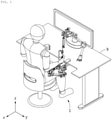
- FIG. 1 is a perspective view illustrating the usage of an arm rest apparatus according to an embodiment of the present invention
- FIG. 2 is a perspective view of the arm rest apparatus according to the embodiment of the present invention.
- the arm rest apparatus 1 can support movement of a user's arm on a work space.
- the arm rest apparatus 1 is fixed on an external object 9 like a desk in order to support the user's arm movements in all poses on the work space.
- the arm rest apparatus 1 can relieve the degree of fatigue according to the user's arm movements and promote a horizontal movement to which fixing and damping are applied, so that the user can move the arm accurately.
- the arm rest apparatus 1 includes a fixed part 11, a horizontal movement module 13, a damping part 12, and an arm support module 14.
- the fixed part 11 is fixed on an external object 9 to provide a driving standard location of the arm rest apparatus 1.
- the fixed part 11 includes: a fixing base 112 capable of being fixed to an external object; and a support base 111 connected to the fixing base 112 to support the horizontal movement module 13 and the arm support module 14 to be able to drive.
- the fixing base 112 can be fixed onto the external object 9, such as a desk, a shelf, and a table.
- the support base 111 is fixed from the fixing base 112 to provide a relative rotation or a movement standard point of the horizontal movement module 13.
- the horizontal movement module 13 can show the two-degree-of-freedom movement in the horizontal direction with respect to the fixed part 11. For instance, an end of the horizontal movement module 13 is rotatably connected around the support base 111, and the other end of the horizontal movement module 13 moves in the horizontal direction of the fixed part 11 and rotatably supports the arm support module 14.
- the damping part 12 is connected to the horizontal movement module 13 so as to form resistance against the movement of the horizontal movement module 13.
- the resistance formed by the damping part 12 is controllable, so that the horizontal movement module 13 does not move completely and can change the movement speed even though the user applies uniform power.
- the arm support module 14 is movably supported by the horizontal movement module 13 to support the user's arm.
- the arm support module 14 includes two arm supporters 143 and 147 which are reciprocally rotatable around rotary shafts respectively parallel with the horizontal direction where the horizontal movement module 13 moves.
- the horizontal direction based on the fixed part 11 is a direction on the plane parallel with the ground (the x-axis and y-axis in the drawing), and the vertical direction is a direction vertical to the ground (the z-axis in the drawing), but the horizontal direction and the vertical direction may be different from the coordinate axis of the ground according to the fixed position of the fixed part 11.
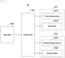
- FIG. 3 is a block diagram of the arm rest apparatus according to the embodiment of the present invention
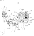
- FIG. 4 is a perspective view of a horizontal movement module according to the embodiment of the present invention
- FIG. 5 is a plan view briefly illustrating an operational structure of the horizontal movement module according to the embodiment of the present invention.
- the horizontal movement module 13 includes a first driving frame 131, a second driving frame 132, a central connection part 133, a rotational end part 134, and a plurality of links 135, 136 and 137.
- the first driving frame 131 can rotate around a first rotary shaft (A) on the fixed part 11.
- a first driving frame 13 can be connected onto the support base 111 to be rotatable around the first rotary shaft (A)
- the other end of the first driving frame 13 can be connected onto the central connection part 133 to be rotatable around a second rotary shaft (B) parallel with the first rotary shaft (A).
- the first driving frame 131 includes a first link 1311 connected between the first rotary shaft (A) and the second rotary shaft (B), and a first protrusion member 1312 fixed from the first link 1311 to rotate around the first rotary shaft (A).
- At least a portion of the first protrusion member 1312 may have an arc-shaped edge protruding radially around the first rotary shaft (A) from the first link 1311.
- the first protrusion member 1312 is connected with a first damping part 121 which will be described later in order to form a resistance against the rotational motion of the first link 1311.
- the first protrusion member 1312 includes a first contact surface 13121 which gets in contact with a first damping member 1213 of the first damping part 121 along the arc-shaped edge.
- the second driving frame 132 may have a three-joint link structure including three-point links 1322, 1321 and 1323 rotatably connected between the first rotary shaft (A) of the fixed part 11 and the second rotary shaft (B) of the central connection part 133.
- the second driving frame 132 includes: a driving link 1322 connected to the fixed part to be rotatable around the first rotary shaft (A); a second link 1321 connected to the driving link 1322 to be rotatable around a third rotary shaft (G) parallel with the first rotary shaft (A); and a third link 1323 of which an end is connected to the second link 1321 to be rotatable around a fourth rotary shaft (H) spaced apart from the third rotary shaft (G) in parallel and of which the other end is connected to the central connection part 133 to be rotatable around the second rotary shaft (B).
- the driving link 1322 is rotatably connected to the first rotary shaft (A) so that at least a portion has an arc-shaped edge protruding radially.
- the driving link 1322 may be called a second protrusion member 1322.
- the second protrusion member 1322 includes a second contact surface 13221 which gets in contact with the second damping member 1223 of the second damping part 122 along the arc-shaped edge.
- the first driving frame 131 and the second driving frame 132 may have a four-joint link structure, and the second link 1321 has the same length as a first link 1311 and the driving link 1322 has the same length as the third link 1323.
- the links 1311, 1321, 1322 and 1323 may form a parallelogram to keep the facing links in parallel.
- Such a parallelogram structure can secure uniform stiffness even though a relatively light material is used, since having stiffness higher than other power transmission structures.
- some of the links 1311, 1321, 1322 and 1323 can be manufactured as a carbon fiber pipe which is five to ten times superior in stiffness to aluminum or steel pipe. So, the links can provide a lighter and stronger structure.
- the central connection part 133 is connected from the first driving frame 131 and the second driving frame 132 and can move from the fixed part 11 in the horizontal direction to the fixed part 11.
- the rotational end part 134 can be connected to the central connection part 133 through a plurality of the links 135 and 137 to be rotatable and movable, and includes an arm rotary shaft (C) on which the arm support module 14 will be mounted to be rotatable.
- the arm rotary shaft (C) is parallel with the first rotary shaft (A).
- the damping part for forming resistance against relative rotational motion between the members connected onto the arm rotary shaft (C) is mounted on the arm rotary shaft (C).
- the damping part provides a damping function to the movement of the arm rest apparatus 1 on the plane.
- a plurality of the links 135, 136 and 137 are a fourth link 135, a fifth link 136, and a sixth link 137.
- the fourth link 135 has an end which is connected to the central connection part 133 to be rotatable around the second rotary shaft (B) and the other end which is connected to the rotational end part 134 to be rotatable around the fifth rotary shaft (F) parallel with the first rotary shaft (A).
- the fourth link 135 can be fixed to the third link 1323. So, when the third link 1323 rotates around the second rotary shaft (B), the fourth link 135 can rotate at the same time. In other words, the fourth link 135 and the third link 1323 can do a rigid body motion. From such a standpoint, it can be understood that the fourth link 135 and the third link 1323 may respectively designate different parts of one link.
- the fifth link 136 has an end which is connected to the fixed part 11 to be rotatable around the sixth rotary shaft (D) spaced apart from the first rotary shaft (A) and being parallel with the first rotary shaft (A) and the other end which is connected to the central connection part 133 to be rotatable around a seventh rotary shaft (E) spaced apart from the second rotary shaft (B) and being parallel with the second rotary shaft (B).
- the fifth link 136 has the same length as the first link 1311. That is, the distance and direction that the sixth rotary shaft (D) is spaced apart from the first rotary shaft (A) on the fixed part 11 are equal to the distance and direction that the seventh rotary shaft (E) is spaced apart from the second rotary shaft (B) on the central connection part 133.
- the first link 1311 and the fifth link 136 can always keep a parallel state so that the first link 1311 and the fifth link 136 between the fixed part 11 and the central connection part 133 provides a parallelogram joint structure to connect the first rotary shaft (A), the second rotary shaft (B), the seventh rotary shaft (E), and the sixth rotary shaft (D).
- At least one of the links 1311 and 136 which form the parallelogram can be manufactured as a carbon fiber pipe.
- the sixth link 137 has an end which is connected to the central connection part 133 to be rotatable around an eighth rotary shaft (I) spaced apart from the second rotary shaft (B) in parallel, and the other end which is connected to the rotational end part 134 to be rotatable around a ninth rotary shaft (J) spaced apart from the fifth rotary shaft (F) in parallel.
- the sixth link 137 has the same length as the fourth link 135. That is, the distance and direction that the eighth rotary shaft (I) is spaced apart from the second rotary shaft (B) on the central connection part 133 are equal to the distance and direction that the ninth rotary shaft (J) is spaced apart from the fifth rotary shaft (F) on the rotational end part 134.
- the fourth link 135 and the sixth link 137 can always keep a parallel state so that the fourth link 135 and the sixth link 137 between the central connection part 133 and the rotational end part 134 provides a parallelogram joint structure to connect the second rotary shaft (B), the fifth rotary shaft (F), the eighth rotary shaft (I), and the ninth rotary shaft (J).
- At least one of the links 135 and 137 which form the parallelogram can be manufactured as a carbon fiber pipe.
- the arm rotary shaft (C) on the rotational end part 134 is formed at a point that is spaced apart from the fifth rotary shaft (F) and the ninth rotary shaft (J) in parallel, and the arm support module 14 is mounted to be rotatable around the arm rotary shaft (C) on the rotational end part 134.
- the support base 111, the central connection part 133, and the rotational end part 134 may be also called as “links".
- the support base 111 may be called a "fixed link” in that it is not moved relatively against the external object 9.
- the rotational end part 134 on which the arm support module 14 is mounted can show the two-degree-of-freedom movement in the horizontal direction with respect to the fixed part 11.
- the arm rest apparatus 1 includes (i) a first four-bar link structure, (ii) a second four-bar link structure which shares any one link with the first four-bar link, and (iii) a third four-bar link structure which shares another link with the first four-bar link and has a link fixed to any one link of the second four-bar link structure.
- any one among four links of the first four-bar link structure is the support base 111 which is fixed to the external object 9 to serve as a standard frame.
- the first four-bar link structure includes the support base 111, the central connection part 133 spaced apart from the support base 111, and a pair of the links 1311 and 136 for connecting the support base 111 and the central connection part 133 with each other.
- the central connection part 133 shows the one-degree-of-freedom movement with respect to the support base 111.
- each of the links 1311 and 136 is longer than the maximum distance between the links 1311 and 136. Therefore, a movement radius of the central connection part 133 with respect to the support base 111 can be secured sufficiently.
- the one link of the first four-bar link structure which is shared with the second four-bar link structure, may be the central connection part 133 which is not directly connected to the support base 111.
- the second four-bar link structure includes the central connection part, the rotational end part 134 spaced apart from the central connection part 133, and a pair of the links 135 and 137 for connecting the central connection part 133 and the rotational end part 134 with each other.
- the rotational end part 134 shows one-degree-of-freedom movement with respect to the central connection part 133
- the rotational end part 134 shows two-degree-of-freedom movement with respect to the support base 111.
- each of the links 135 and 137 is longer than the maximum distance between the links 135 and 137. Therefore, a work space of the rotational end part 134 with respect to the support base 111 can be secured sufficiently.
- such a four-bar link structure is greater in stiffness than the linear mechanism, but is narrower in work space than the linear mechanism.
- the arm rest apparatus 1 using the two four-bar link structures that share one link with each other like the present invention can overcome the problem of the conventional four-bar link structure, and provide high stiffness in a wide work space.
- One link of the first four-bar link structure which is shared with the third four-bar link structure may be any one link 1311 among a pair of the links 1311 and 136 which is directly connected to the support base 111.
- one link of the second four-bar link structure which is fixed to any one link of the third four-bar link structure to be moved integrally with the link of the third four-bar link structure may be any one link 135 among a pair of the links 135 and 137 directly connected to the central connection part 133.
- the third four-bar link structure includes the first link 1311, the second link 1321 spaced apart from the first link 1311, and a pair of the links 1322 and 1323 for connecting the first link 1311 and the second link 1321 with each other.
- any one link 1323 among the links 1322 and 1323 is fixed to any one link 135 among the links 135 and 137 of the second four-bar link structure to be moved integrally with the link of the second four-bar link structure.
- the present invention can provide a more stable structure.
- the damping part for forming resistance against the movement of the second four-bar link structure can be arranged at a position adjacent to the fixed part 11, for instance, a specific position on the fixed part 11 or a specific position on the external object 9, it can prevent that the inertia moment of the arm rest apparatus 1 is increased.
- each of the three four-bar link structures has the parallelogram structure.
- Such a design can prevent generation of singularity during movement of the four-bar link structure so as to reduce the problem that the work space of the rotational end part 134 is limited.
- the present invention is not limited to the above, and some or all of the three four-bar link structures may not be the parallelogram structure.
- the arm rest apparatus 1 can enhance durability and movement stability since having the structure that can effectively disperse the user's arm weight and a vertical load of the arm support module 14 since a plurality of the links guide and support mutual movement and rotation.
- a plurality of the links may be empty hollow members.
- the damping part 12 includes the first damping part 121, the second damping part 122, a control part 123, and an input part 124. At least a portion of the damping part 12 is mounted at a portion of the arm rest apparatus 1 that there is no movement, namely, at the fixed part 11, so as to prevent that the inertia moment of the arm rest apparatus 1 is increased. In another example, at least a portion of the damping part 12 may be mounted on the external object 9.
- the first damping part 121 may form resistance against the rotational motion of the first driving frame 131.
- the first damping part 121 includes: a first damping member 1213 connected to the first protrusion member 1312 to transfer a resistance according to a rotational motion of the first driving frame 131; a first driving source 1211 connected to the first damping member 1213 to form a resistance and to adjust intensity of the resistance; and a first brake 1212 which firmly fixes the first damping member 1213 to prevent rotation of the first driving frame 131.
- the first damping member 1213 gets in contact with the first contact surface 13121, which is rounded, of the first protrusion member 1312.
- the connection between the first damping member 1213 and the first contact surface 13121 may be formed through various rotation transmission elements, such as gear coupling, screw coupling, friction material joining, and so on.
- the first driving source 1211 can form a rotational resistance to the first damping member 1213 connected to the first contact surface 13121 and adjust intensity of the resistance. Additionally, the first driving source 1211 may be a driving source, such as a motor or a cylinder which can form rotary power with electric energy, pneumatic energy or hydraulic energy.
- the first brake 1212 fixes the first damping member 1213, which is connected to the first contact surface 13121, not to rotate so that the first driving frame 131 is not rotated around the first rotary shaft (A).
- the first brake 1212 may be an electromagnetic brake which is operated by an electromagnetic method to press the first damping member 1213 powerfully.
- the second damping part 122 can form a resistance against the rotational motion of the second driving frame 132.
- the second damping part 122 includes: a second damping member 1223 connected to the second protrusion member 1322 to transfer a resistance according to a rotational motion of the second driving frame 132; a second driving source 1221 connected to the second damping member 1223 to form a resistance and to adjust intensity of the resistance; and a second brake 1222 which firmly fixes the second damping member 1223 to prevent rotation of the second driving frame 132.
- the second driving source 1221 can form a rotational resistance to the second damping member 1223 connected to the second contact surface 13221 and adjust intensity of the resistance. Additionally, the second driving source 1221 may be a driving source, such as a motor or a cylinder which can form rotary power with electric energy, pneumatic energy or hydraulic energy.
- the second brake 1222 fixes the second damping member 1223, which is connected to the second contact surface 13221, not to rotate so that the second driving frame 132 is not rotated around the first rotary shaft (A).
- the second brake 1222 may be an electromagnetic brake which is operated by an electromagnetic method to press the second damping member 1223 powerfully.
- the present invention can form a resistance according to the two-rotational-degree-of-freedom movement of the arm support module 14.
- the first damping part 121 forms a resistance with respect to the movement with a first rotational degree of freedom ( ⁇ 1 ) that the first driving frame 131 rotates around the first rotary shaft (A), so as to suppress the tendency that the central connection part 133 rotates with respect to the fixed part 11.
- the second damping part 122 forms a resistance with respect to the movement with a second rotational degree of freedom ( ⁇ 2 ) that the second driving frame 132, namely, the driving link 1322, rotates around the first rotary shaft (A), so as to suppress the tendency that the rotational end part 134 rotates with respect to the central connection part 133.
- the damping part 12 forms damping power to resist against power applied to the rotational end part 134 according to changes in the user's arm movements and poses, so that the user can guide to move the arm accurately and slowly.
- the user can adjust intensity of the resistance formed by the first damping part 121 or the second damping part 122 so as to provide appropriate damping control according to kinds of work, accuracy, or the user's taste.
- the first brake 1212 or the second brake 1222 is operated to suppress rotation of the first driving frame 131 or the second driving frame 132 in order to prevent the horizontal movement of the rotational end part 134. Therefore, the user's arm supported by the arm support module 14 can be fixed in horizontal position or pose. So, the arm rest apparatus according to the present invention is effective in performing work requiring accurate movements utilizing tiny muscles below the wrist.
- the arm rest apparatus 1 can selectively induce arm movements according to kinds of work or arm movement races.
- the control part 123 operates the first damping part 121 or the second damping part 122 so that the first driving frame 131 or the second driving frame 132 can form a resistance against the rotational motion performed around the first rotary shaft (A), and adjusts intensity of the resistance.
- the control part 123 operates the first brake 1212 or the second brake 1222 so that the first driving frame 131 or the second driving frame 132 can suppress the rotational motion performed around the first rotary shaft (A).
- the input part 124 includes an interface which receives an input signal from the user in order to control the first damping part 121 or the second damping part 122.
- first damping part 121 and the second damping part 122 respectively and individually form resistances against the rotational motions of the driving frames 131 and 132.
- first protrusion member 1312 of the first driving frame 131 and the driving link 1322 of the second driving frame 132 rotate around the same rotary shaft (A)
- the first damping member 1213 getting in contact with the first protrusion member 1312 and the second damping member 1223 getting in contact with the second protrusion member 1322 are respectively parts of the same component.
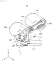
- FIG. 6 is a perspective view of an arm support module according to the embodiment of the present invention
- FIGS. 7 and 8 are side views of the arm support module according to the embodiment of the present invention.
- the arm support module 14 includes a connection part 141, a first support part 144, a first arm supporter 143, a rotary link 145, a second support part 146, a second arm supporter 147, and a weight compensation part 148.
- connection part 141 is mounted on the rotational end part 134 to be rotatable around the arm rotary shaft (C).
- the first support part 144 is fixed to the connection part 141 to support the first arm supporter 143. Moreover, the first support part 144 is formed integrally with the connection part 141 to be rotated around the arm rotary shaft (C) .
- the first arm supporter 143 can support the user's arm.
- the first arm supporter 143 can support the user's arm, namely, a part near to the elbow.
- the surface of the first arm supporter 143 has a shape of which both edge portions are curved upwards so that the user's arm is put on the first arm supporter stably to be supported.
- the first arm supporter 143 is overlapped with the arm rotary shaft (C) in order to stably guide the rotational motion of the forearm part based on the elbow joint.
- the rotary link 145 may be a link that one side is rotatably connected to the first support part 144 and the other side is connected to the second support part 146.
- the rotary link 145 can rotate around an inclination adjustment shaft (K) with respect to the first support part 144, and the inclination adjustment shaft (K) is vertical to the arm rotary shaft (C).
- the damping part which forms the resistance against the relative rotational motion of the members connected to the inclination adjustment shaft (K) is mounted on the inclination adjustment shaft (K). Such a damping part provides damping force to the movements of the arm rest apparatus 1.
- the second support part 146 is connected to the rotary link 145 to support the second arm supporter 147.
- the second arm supporter 147 can support the user's arm.
- the second arm supporter 147 can support the user's arm, namely, a part near to the elbow.
- the surface of the second arm supporter 147 has a shape of which both edge portions are curved upwards so that the user's arm is put on the first arm supporter stably to be supported.
- the weight compensation part 148 can compensate influences of the weight of the user's arm and the weight of the arm support module 14.
- the weight compensation part 148 includes an elastic body 1481 mounted on the rotary link 145, and a wire 1482 connected between the elastic body 1481 and the first support part 144.
- the elastic body 1481 has an end fixed to the rotary link 145 and the other end connected to the wire 1482. As illustrated in FIGS. 6 to 8 , the elastic body 1481 may be a spring mounted to be expandable in the longitudinal direction of the rotary link 145.
- the wire 1482 applies tensile force to the elastic body 1481 between the elastic body 1481 and the first support part 144. Due to the structure of the wire 1482, intensity of the tensile force applied to the elastic body 1481 can be adjusted according to a rotational angle formed with respect to the inclination adjustment shaft (K).
- a part where the wire 1482 is connected to the first support part 144 is formed above a part where the inclination adjustment shaft is located at the first support part 144 in the vertical direction.
- the part where the wire 1482 is fixed to the first support part 144 may be called a wire fixing part 1441.
- a distance between the wire fixing part 1441 and an end portion of the elastic body 1481 gets further as the rotary link 145 gets further from the ground in the vertical direction (z-axis direction).
- the restoring force of the elastic body 1481 can form power to upwardly move the second arm supporter 147 relative to the first arm supporter 143, while the user's forearm pose is changed to be inclined upwards, influences of weight of the user's arm and weight of the arm support module 14 can be reduced or compensated.
- the rotary link 145 includes a guide pulley 1451 for guiding a connection direction of the wire 1482 between the first support part 144 and the elastic body 1481 in order to keep the direction of tensile force transferred to the elastic body 1481 from the wire 1482 in parallel with the direction of the rotary link 145.
- the tensile force applied to the elastic body 1481 can be adjusted approximately linearly according to the rotational angle of the rotary link 145.
- the rotary link 145 includes an interference part 1452, which is interfered by the first support part 144, in order not to be rotated beyond a set angle with respect to the first support part 144.
- the interference part 1452 is interfered by the first support part 144 so that the rotary link 145 is not rotated in a downwardly inclined direction from the inclined adjustment shaft.
- the arm rest apparatus 1 can stably guide the two-degree-of-freedom movement in the horizontal direction in the state where the user's arm is supported, and at the same time, the arm support module 14 can stably compensate weight of the arm in various poses by applying a gravity compensation mechanism according to a vertical inclination of the arm.
- the arm rest apparatus 1 can ergonomically support the user's arm in all poses and minimize the user's fatigue according to movements.
- the arm rest apparatus 1 according to the embodiment of the present invention can show accurate and exact movement according to characteristics of work since the damping part 12 can control damping according to the horizontal movement of the arm.
- the arm rest apparatus 1 can filter unintended fast and big movement of the arm so as to prevent an unexpected injury formed on the patient's lesion.
- the arm rest apparatus 1 is very effective for accurate work utilizing tiny muscles below the wrist since the brakes 1212 and 1222 can fix the horizontal position of the arm support module 14.
Landscapes
- Engineering & Computer Science (AREA)
- Mechanical Engineering (AREA)
- Robotics (AREA)
- Health & Medical Sciences (AREA)
- General Health & Medical Sciences (AREA)
- Nursing (AREA)
- Surgery (AREA)
- Life Sciences & Earth Sciences (AREA)
- Medical Informatics (AREA)
- Veterinary Medicine (AREA)
- Biomedical Technology (AREA)
- Molecular Biology (AREA)
- Animal Behavior & Ethology (AREA)
- Pathology (AREA)
- Public Health (AREA)
- Heart & Thoracic Surgery (AREA)
- Oral & Maxillofacial Surgery (AREA)
- Nuclear Medicine, Radiotherapy & Molecular Imaging (AREA)
- Dentistry (AREA)
- Manipulator (AREA)
- Transmission Devices (AREA)
- Mechanical Control Devices (AREA)
Applications Claiming Priority (2)
| Application Number | Priority Date | Filing Date | Title |
|---|---|---|---|
| KR1020190047445A KR102218798B1 (ko) | 2019-04-23 | 2019-04-23 | 암 레스트 장치 |
| PCT/KR2020/004534 WO2020218752A2 (fr) | 2019-04-23 | 2020-04-02 | Dispositif d'accoudoir |
Publications (2)
| Publication Number | Publication Date |
|---|---|
| EP3960027A2 true EP3960027A2 (fr) | 2022-03-02 |
| EP3960027A4 EP3960027A4 (fr) | 2023-01-18 |
Family
ID=72941098
Family Applications (1)
| Application Number | Title | Priority Date | Filing Date |
|---|---|---|---|
| EP20793988.5A Pending EP3960027A4 (fr) | 2019-04-23 | 2020-04-02 | Dispositif d'accoudoir |
Country Status (5)
| Country | Link |
|---|---|
| US (2) | US12245688B2 (fr) |
| EP (1) | EP3960027A4 (fr) |
| KR (1) | KR102218798B1 (fr) |
| CN (1) | CN113710429B (fr) |
| WO (1) | WO2020218752A2 (fr) |
Families Citing this family (5)
| Publication number | Priority date | Publication date | Assignee | Title |
|---|---|---|---|---|
| KR102502444B1 (ko) * | 2020-11-13 | 2023-02-23 | 주식회사 로엔서지컬 | 수술용 이중 패러렐로그램 장치 |
| CN115054477B (zh) * | 2022-05-07 | 2023-07-07 | 浙江豪中豪健康产品有限公司 | 一种带锁扣的四连杆阻尼槽扶手开合机构 |
| CN115429434B (zh) * | 2022-09-20 | 2024-07-23 | 上海神玑医疗科技有限公司 | 阻尼关节、机械臂及手术机器人 |
| US20240115050A1 (en) * | 2022-10-05 | 2024-04-11 | MillerKnoll, Inc. | Arm support |
| KR20260001348A (ko) * | 2024-06-27 | 2026-01-05 | 현대모비스 주식회사 | 매니퓰레이터 로봇 |
Family Cites Families (35)
| Publication number | Priority date | Publication date | Assignee | Title |
|---|---|---|---|---|
| US3124328A (en) * | 1964-03-10 | kortsch | ||
| US1266367A (en) * | 1915-05-08 | 1918-05-14 | Ira H Wilson | Adjustable support or rest. |
| US1516795A (en) * | 1922-07-14 | 1924-11-25 | Schwarting Louise | Limb support for operating tables |
| US2119325A (en) * | 1936-12-31 | 1938-05-31 | Jacob A Goodhart | Surgical splint |
| US2614558A (en) * | 1950-04-01 | 1952-10-21 | Lovell Edgar Sherburne | Fracture supporting device |
| US4592526A (en) * | 1981-08-24 | 1986-06-03 | Jacob Kobelt | Adjustable holding device |
| JPS61121880A (ja) * | 1984-11-19 | 1986-06-09 | 松下電器産業株式会社 | 直接駆動方式ロボツト |
| US5884974A (en) * | 1991-09-05 | 1999-03-23 | Industrial Ergonomics | Ergonomic arm support and bracket |
| SE505551C2 (sv) * | 1993-04-20 | 1997-09-15 | Ergonomiprodukter I Bodafors A | Armstödsanordning för en stol |
| US5655814A (en) * | 1996-03-07 | 1997-08-12 | Shin Yeh Enterprise Co., Ltd. | Adjustable chair-armrest assembly |
| US6042064A (en) * | 1997-08-28 | 2000-03-28 | Hong; Kwang Y. | Wrist support |
| US6663055B2 (en) * | 2000-03-15 | 2003-12-16 | The Or Group, Inc. | Armboard assembly |
| US6704959B2 (en) * | 2001-08-13 | 2004-03-16 | Peter Schuerch | Adjustable position limb support for surgical tables |
| KR200280389Y1 (ko) * | 2002-03-11 | 2002-07-04 | 길종진 | 컴퓨터 작업용 암레스트 장치 |
| US7222826B1 (en) * | 2002-11-23 | 2007-05-29 | Andrew Berglund | Adaptive arm support |
| EP1486178B1 (fr) * | 2003-06-12 | 2006-10-04 | University of Dundee | Dispositif pour soutient d'au moins un bras d'une personne pratiquant une operation chirurgicale |
| US6786461B1 (en) * | 2003-07-30 | 2004-09-07 | Horng Sheng Lih Enterprise Co., Ltd. | Computer armrest |
| JP3783011B2 (ja) * | 2003-10-02 | 2006-06-07 | 株式会社日立製作所 | 操作入力装置および遠隔操作システムおよび遠隔操作方法 |
| EP1669038B1 (fr) * | 2004-12-09 | 2008-02-20 | The University of Dundee | Repose-bras pour chirurgicien ou dentiste |
| DE102006004126B4 (de) * | 2006-01-25 | 2007-11-29 | Karl Storz Gmbh & Co. Kg | Chirurgische Armstütze |
| CA2697600C (fr) * | 2007-08-30 | 2017-03-14 | Garrett W. Brown | Support de bras humain articule |
| US8006850B2 (en) * | 2009-01-30 | 2011-08-30 | Randy Rotheisler | Articulated jib |
| US10792183B2 (en) * | 2011-10-06 | 2020-10-06 | Saebo, Inc. | Mobile arm support |
| JP5545337B2 (ja) * | 2012-09-28 | 2014-07-09 | 株式会社安川電機 | ロボットアームおよびロボット |
| KR101434870B1 (ko) * | 2013-02-19 | 2014-09-02 | 한양대학교 에리카산학협력단 | 의료 광학 기구용 스탠드 |
| KR102237597B1 (ko) * | 2014-02-18 | 2021-04-07 | 삼성전자주식회사 | 수술 로봇용 마스터 장치 및 그 제어 방법 |
| CN203790256U (zh) * | 2014-03-12 | 2014-08-27 | 武汉理工大学 | 上肢康复训练装置 |
| KR101603162B1 (ko) * | 2014-11-24 | 2016-03-17 | 대한민국 | 모터에 의하여 하중을 보상하는 상지 보조 장치 |
| KR101539910B1 (ko) * | 2015-03-16 | 2015-07-29 | 주식회사 케디엠 | 부품 조립용 인간협업 양팔 보조장치 |
| KR101731910B1 (ko) * | 2015-11-25 | 2017-05-04 | (주)아리테크 | 암레스트 |
| US10058994B2 (en) * | 2015-12-22 | 2018-08-28 | Ekso Bionics, Inc. | Exoskeleton and method of providing an assistive torque to an arm of a wearer |
| US10569413B2 (en) * | 2015-12-22 | 2020-02-25 | Ekso Bionics, Inc. | Exoskeleton and method of providing an assistive torque to an arm of a wearer |
| KR101839946B1 (ko) * | 2016-09-13 | 2018-03-22 | 주식회사 고영테크놀러지 | 의료용 스탠드 |
| KR101903904B1 (ko) * | 2017-02-23 | 2018-11-13 | 고려대학교 산학협력단 | 중력보상에 기반한 수동식 자세유지장치 |
| KR102053397B1 (ko) * | 2017-06-30 | 2019-12-06 | 주식회사 네오펙트 | 상지 재활 로봇 |
-
2019
- 2019-04-23 KR KR1020190047445A patent/KR102218798B1/ko active Active
-
2020
- 2020-04-02 WO PCT/KR2020/004534 patent/WO2020218752A2/fr not_active Ceased
- 2020-04-02 EP EP20793988.5A patent/EP3960027A4/fr active Pending
- 2020-04-02 CN CN202080029731.2A patent/CN113710429B/zh active Active
-
2021
- 2021-10-18 US US17/503,858 patent/US12245688B2/en active Active
-
2025
- 2025-01-17 US US19/026,558 patent/US20250151894A1/en active Pending
Also Published As
| Publication number | Publication date |
|---|---|
| CN113710429B (zh) | 2024-12-17 |
| WO2020218752A2 (fr) | 2020-10-29 |
| CN113710429A (zh) | 2021-11-26 |
| US12245688B2 (en) | 2025-03-11 |
| EP3960027A4 (fr) | 2023-01-18 |
| KR102218798B1 (ko) | 2021-02-24 |
| WO2020218752A3 (fr) | 2020-12-24 |
| US20250151894A1 (en) | 2025-05-15 |
| US20220031065A1 (en) | 2022-02-03 |
| KR20200124056A (ko) | 2020-11-02 |
Similar Documents
| Publication | Publication Date | Title |
|---|---|---|
| US12245688B2 (en) | Arm rest apparatus | |
| AU2008293511B2 (en) | Articulated human arm support | |
| JP7544918B2 (ja) | マルチアクティブ軸の非外骨格リハビリテーション装置 | |
| JP7443029B2 (ja) | ウェアラブル筋力補助装置の上腕モジュール及びこれを含むウェアラブル筋力補助装置 | |
| KR101603162B1 (ko) | 모터에 의하여 하중을 보상하는 상지 보조 장치 | |
| KR102284387B1 (ko) | 수술 시스템 | |
| JP2017512666A (ja) | 重量用腕サポートシステム | |
| US12257167B2 (en) | Movement assistance apparatus, e.g., for feeding, writing | |
| CN112894765B (zh) | 可穿戴式肌肉力量辅助装置 | |
| US10837597B2 (en) | Counterbalancing apparatus for gimbal joints and/or a method for counterbalancing a load on a gimbal joint | |
| KR101500200B1 (ko) | 로봇의 하중 지지 장치 | |
| KR102283670B1 (ko) | 슬레이브 장치를 제어하기 위한 수술용 마스터 장치 | |
| WO2021021679A1 (fr) | Système de support de corps inférieur pour faciliter l'exécution d'une tâche de niveau de sol par des êtres humains | |
| KR102663601B1 (ko) | 착용식 근력 보조 장치의 상완 모듈 및 이를 포함한 착용식 근력 보조 장치 | |
| KR20200097154A (ko) | 플라이휠을 이용한 상지운동기구 | |
| KR102334392B1 (ko) | 다자유도 움직임이 가능한 착용형 중력 보상 장치 | |
| JP7775775B2 (ja) | アシストデバイス | |
| KR102285586B1 (ko) | 수술용 마스터 장치에 사용되는 그리퍼 | |
| CN222032590U (zh) | 操作主手、医生控制台以及腹腔内窥镜手术机器人 | |
| KR102628161B1 (ko) | 어깨 재활 장치 | |
| WO2012027433A1 (fr) | Système de support combiné | |
| CN120038723A (zh) | 一种宽自由的无级调节自适应外骨骼 | |
| WO2025085045A2 (fr) | Mécanisme de déplacement pour exosquelettes | |
| CN119454410A (zh) | 一种3自由度穿戴式上肢康复外骨骼机构 | |
| CN115778755A (zh) | 一种手腕康复装置及上肢康复机器人 |
Legal Events
| Date | Code | Title | Description |
|---|---|---|---|
| STAA | Information on the status of an ep patent application or granted ep patent |
Free format text: STATUS: THE INTERNATIONAL PUBLICATION HAS BEEN MADE |
|
| PUAI | Public reference made under article 153(3) epc to a published international application that has entered the european phase |
Free format text: ORIGINAL CODE: 0009012 |
|
| STAA | Information on the status of an ep patent application or granted ep patent |
Free format text: STATUS: REQUEST FOR EXAMINATION WAS MADE |
|
| 17P | Request for examination filed |
Effective date: 20211101 |
|
| AK | Designated contracting states |
Kind code of ref document: A2 Designated state(s): AL AT BE BG CH CY CZ DE DK EE ES FI FR GB GR HR HU IE IS IT LI LT LU LV MC MK MT NL NO PL PT RO RS SE SI SK SM TR |
|
| DAV | Request for validation of the european patent (deleted) | ||
| DAX | Request for extension of the european patent (deleted) | ||
| A4 | Supplementary search report drawn up and despatched |
Effective date: 20221221 |
|
| RIC1 | Information provided on ipc code assigned before grant |
Ipc: A47C 16/00 20060101ALI20221215BHEP Ipc: B25J 13/02 20060101ALI20221215BHEP Ipc: B25J 9/10 20060101ALI20221215BHEP Ipc: A61B 90/60 20160101ALI20221215BHEP Ipc: A47C 7/54 20060101ALI20221215BHEP Ipc: A47B 21/03 20060101AFI20221215BHEP |
|
| RAP3 | Party data changed (applicant data changed or rights of an application transferred) |
Owner name: ROEN SURGICAL, INC. Owner name: KOREA ADVANCED INSTITUTE OF SCIENCE AND TECHNOLOGY |
|
| GRAP | Despatch of communication of intention to grant a patent |
Free format text: ORIGINAL CODE: EPIDOSNIGR1 |
|
| STAA | Information on the status of an ep patent application or granted ep patent |
Free format text: STATUS: GRANT OF PATENT IS INTENDED |
|
| RIC1 | Information provided on ipc code assigned before grant |
Ipc: A47B 21/03 20060101AFI20251014BHEP Ipc: A47C 7/54 20060101ALI20251014BHEP Ipc: A61B 90/60 20160101ALI20251014BHEP Ipc: B25J 9/10 20060101ALI20251014BHEP Ipc: B25J 13/02 20060101ALI20251014BHEP Ipc: A47C 16/00 20060101ALI20251014BHEP |
|
| INTG | Intention to grant announced |
Effective date: 20251103 |
|
| GRAS | Grant fee paid |
Free format text: ORIGINAL CODE: EPIDOSNIGR3 |
|
| GRAA | (expected) grant |
Free format text: ORIGINAL CODE: 0009210 |
|
| STAA | Information on the status of an ep patent application or granted ep patent |
Free format text: STATUS: THE PATENT HAS BEEN GRANTED |