EP3960044B1 - Capsule pour l'infusion de boisson - Google Patents
Capsule pour l'infusion de boisson Download PDFInfo
- Publication number
- EP3960044B1 EP3960044B1 EP20795117.9A EP20795117A EP3960044B1 EP 3960044 B1 EP3960044 B1 EP 3960044B1 EP 20795117 A EP20795117 A EP 20795117A EP 3960044 B1 EP3960044 B1 EP 3960044B1
- Authority
- EP
- European Patent Office
- Prior art keywords
- filter
- maze
- capsule
- beverage
- laminar membrane
- Prior art date
- Legal status (The legal status is an assumption and is not a legal conclusion. Google has not performed a legal analysis and makes no representation as to the accuracy of the status listed.)
- Active
Links
Images


Classifications
-
- B—PERFORMING OPERATIONS; TRANSPORTING
- B65—CONVEYING; PACKING; STORING; HANDLING THIN OR FILAMENTARY MATERIAL
- B65D—CONTAINERS FOR STORAGE OR TRANSPORT OF ARTICLES OR MATERIALS, e.g. BAGS, BARRELS, BOTTLES, BOXES, CANS, CARTONS, CRATES, DRUMS, JARS, TANKS, HOPPERS, FORWARDING CONTAINERS; ACCESSORIES, CLOSURES, OR FITTINGS THEREFOR; PACKAGING ELEMENTS; PACKAGES
- B65D85/00—Containers, packaging elements or packages, specially adapted for particular articles or materials
- B65D85/70—Containers, packaging elements or packages, specially adapted for particular articles or materials for materials not otherwise provided for
- B65D85/804—Disposable containers or packages with contents which are mixed, infused or dissolved in situ, i.e. without having been previously removed from the package
- B65D85/8043—Packages adapted to allow liquid to pass through the contents
- B65D85/8055—Means for influencing the liquid flow inside the package
-
- A—HUMAN NECESSITIES
- A47—FURNITURE; DOMESTIC ARTICLES OR APPLIANCES; COFFEE MILLS; SPICE MILLS; SUCTION CLEANERS IN GENERAL
- A47J—KITCHEN EQUIPMENT; COFFEE MILLS; SPICE MILLS; APPARATUS FOR MAKING BEVERAGES
- A47J31/00—Apparatus for making beverages
- A47J31/44—Parts or details or accessories of beverage-making apparatus
- A47J31/46—Dispensing spouts, pumps, drain valves or like liquid transporting devices
-
- B—PERFORMING OPERATIONS; TRANSPORTING
- B65—CONVEYING; PACKING; STORING; HANDLING THIN OR FILAMENTARY MATERIAL
- B65D—CONTAINERS FOR STORAGE OR TRANSPORT OF ARTICLES OR MATERIALS, e.g. BAGS, BARRELS, BOTTLES, BOXES, CANS, CARTONS, CRATES, DRUMS, JARS, TANKS, HOPPERS, FORWARDING CONTAINERS; ACCESSORIES, CLOSURES, OR FITTINGS THEREFOR; PACKAGING ELEMENTS; PACKAGES
- B65D85/00—Containers, packaging elements or packages, specially adapted for particular articles or materials
- B65D85/70—Containers, packaging elements or packages, specially adapted for particular articles or materials for materials not otherwise provided for
- B65D85/804—Disposable containers or packages with contents which are mixed, infused or dissolved in situ, i.e. without having been previously removed from the package
- B65D85/8043—Packages adapted to allow liquid to pass through the contents
- B65D85/8061—Filters
Definitions
- the capsule for infusing a beverage is configured to be able to be inserted into a machine prepared to inject water into the capsule, flooding the interior space of said capsule, in order to finally obtain a liquid mixture formed by the infusion and the water which will come out through a lower outlet mouth.
- an objective of the invention is to achieve an extraction of the beverage that is progressive and gradual, without the water hammer effect, which results in a smooth extraction, without gushing out or splashing.
- the capsule of the invention prevents the generation of irregular opening areas from which parts of the material can be detached from parts of the capsule.
- beverage preparation capsules wherein, after mixing a liquid with a food product such as teas and coffee, said mixture is filtered inside the capsule through a filtering surface.
- Capsules for producing beverages which comprise a filter with a filtering surface in the interior space thereof, through which the mixture passes before being extracted to the outside through a lower mouth of the capsule.
- the filter Due to the pressure reached inside the food beverage preparation capsule when a liquid is injected therein, the filter tends to destabilise and move internally due to the stresses to which said filter is subjected, which causes abnormal operation inside the capsule.
- Another problem that occurs in known capsules is the formation of a crater in the volume of the food product housed inside the capsule when the liquid is injected inside the capsule, such that the formation of said crater creates a channel through which part of the liquid is evacuated directly to the outlet mouth of the capsule with a poor mixture of the tea or coffee; the formation of said crater even being able to cause part of the food product to not be soaked by the liquid injected into the capsule.
- an upper chamber which contains the food product and a lower chamber which may or may not house a filter, such that in some cases both chambers are initially isolated from each other by means of a laminar membrane.
- a laminar membrane In this situation, when water is introduced into the upper chamber, it soaks the food product and at the same time the pressure increases progressively, reaching a moment when the membrane breaks and then the liquid mixture of water and food product reaches the lower chamber, which communicates with an outlet hole through which the mixture is extracted for consumption thereof.
- the breaking of the membrane is carried out by means of physical contact between the membrane and a sharp element, such as in ES 2260626 T3 , such that with the increase in pressure within the upper chamber of the capsule, the membrane moves and comes into contact with the sharp element.
- ES 2555631 B2 describes a capsule for preparing a nutritional beverage with a controlled outlet system, wherein a laminar membrane is attached in a first annular area to a perimeter step of a cup structure and in a central second area the laminar membrane is attached to a central plateau. This second central area is concentric with the first annular area; wherein the passage of fluid is through slits of the laminar membrane which open under the effect of the pressure inside the capsule.
- the laminar membrane breaks due to the increase in pressure inside the upper chamber of the capsule without requiring a sharp element that penetrates the laminar membrane. To do so, the laminar membrane includes specific incisions or notches which constitute weakened areas, and it is through where the membrane finally breaks when the pressure increases sufficiently.
- ES 2359284 T3 refers to a capsule of ingredients for beverages which comprises a cup structure including an upper chamber and a lower chamber which are separated by a filter, such that when the pressure increases inside the upper chamber wherein the food substance is located, the liquid mixture (beverage) of water and the food substance passes into the lower chamber through a perimeter gap which is released as a consequence of the increase in pressure in the upper chamber, such that said perimeter gap is delimited between an internal side face of the cup structure and a perimeter part of the filter adjacent to said internal side face.
- the filter includes direct capillary holes which communicate directly between the upper chamber and the lower chamber.
- Document ES 2709667 T3 discloses a cartridge containing a food substance adapted to interact with water injected in the cartridge to produce a food liquid. It comprises a cup having a chamber for holding the food substance and a lid, a puncturable delivery wall that holds the substance in the chamber, a puncturing structure to puncture at least one opening in the delivery wall as a response of water filling the chamber and a collecting area for collecting the liquid passing through the delivery wall in a substantially axial direction placed downstream the puncturable delivery wall and at least one liquid outlet in the collecting area for allowing the liquid to leave the collecting area.
- the cartridge comprises a support structure comprising at least one support surface configured to support at least one portion of the delivery wall to maintain a flow gap between the puncture structure and the at least one outlet.
- WO 2014033341 A1 discloses a capsule for a beverage maker, comprising a container housing a first chamber into which a pressurised fluid is injected.
- Said first chamber includes holes through which the fluid can pass to a second chamber that contains a product, the fluid being mixed with the edible product.
- the second chamber comprises perforations through which the fluid can pass to a third chamber that opens into an outlet channel that releases the edible product mixed with the fluid.
- a frustoconical support defines the base and forms the first chamber, as well as comprising the above-mentioned holes which are covered with an annular body.
- a plate forms the base of the second chamber and is provided with perforations, said plate, together with the base, forming the third chamber.
- the invention proposes a capsule according to any of claims 1-9.
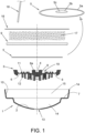
- the capsule for infusing a beverage comprises a cup structure 1 with a perimeter step 7, a cover 16, a filter paper 9, a filter 3 and a laminar membrane 5.
- the cover 16 is attached by means of sealing on an upper perimeter rim 1a which delimits an opening of the cup structure 1.
- the filter 3 is supported on a bottom 2 of the cup structure 1 below the perimeter step 7; wherein said bottom 2 includes an outlet hole 13.
- the laminar membrane 5 is attached to the cup structure 1 by means of a first continuous welded attachment which corresponds with an annular area 5a of the laminar membrane 5 welded to the perimeter step 7 of the cup structure 1.
- the filter paper 9 is attached on a laminar membrane face 5 which is welded to a part of an internal side face 10 of the cup structure 1.
- the laminar membrane 5 together with the filter paper 9 separate a lower chamber 14 and an upper chamber 15 of the cup structure 1; wherein the filter 3 is housed in the lower chamber 14, and wherein the upper chamber 15 is configured to house a food substance 17 which will be in contact with the laminar membrane 5 or with the filter paper 9 when the latter element 9 is incorporated.
- the laminar membrane 5 is also attached to the filter 3 by means of a second annular welded attachment, which is continuous and central, corresponding to a first internal part 5c by way of a central disc of the laminar membrane 5; wherein an area of said first internal part 5c is welded to a raised central plateau 8 that forms part of the filter 3; and wherein said plateau 8 includes a concentric gap 4.
- the laminar membrane 5 includes a continuous circumferential pre-cut 5b which has a diameter greater than the dimension of the contour of the central plateau 8 of the filter 3. Said continuous circumferential pre-cut 5b delimits the area of the first internal part 5c; wherein said continuous circumferential pre-cut 5b is located in a part delimited between the two continuous welded attachments; and wherein the continuous circumferential pre-cut 5b separates the first internal part 5c from a second external part 5d of the laminar membrane 5 including the annular area 5a.
- the filter 3 comprises an upper maze 11 and a lower maze 12 opposing one another which are communicated through at least one communicating hole 6 close to the perimeter edge of the filter 5, although in practice it includes a succession of holes 6 located in a circumferential contour.
- said communicating holes 6 are circular in shape and comprise a measurement delimited between 0.4 mm and 0.8 mm, without ruling out other measurements.
- the lower chamber 14 of the capsule wherein the filter 5 is housed constitutes a discharge and filtration chamber, wherein the water mixed with the food substance 17 flows through the spaces and clearance between the upper maze 11 and the lower maze 12, the water with the food substance being filtered and homogenised as it travels from the periphery of the bottom 2 of the capsule to the central part of said bottom 2 wherein the outlet hole 13 is located and through which the liquid mixture (beverage) of water with the food substance 17 will flow out.
- a cannula 18 of the machine After introducing the capsule of the invention into a machine for infusing a beverage, and operating said machine, one end of a cannula 18 of the machine pierces the cover 16 of the capsule and is inserted into a hollow space existing in the upper part of the capsule, above the food substance 17 housed in the upper chamber 15; all this in order to flood said upper chamber 15 with water in a liquid state.
- the food substance 17 occupies a filling space which is complemented with the hollow space wherein the end of the cannula 18 opens, such that the upper chamber 15 comprises the hollow space and the space occupied by the food substance.
- the cannula 18 introduces hot water into the upper chamber 15 of the capsule, flooding the interior space of said upper chamber 15; wherein during this operation the hot water is mixed with the food substance 17. As the hot water is being introduced, the pressure inside the upper chamber 15 of the capsule progressively increases.
- the controlled breaking of the laminar membrane 5 begins in an area of the continuous circumferential pre-cut 5b thereof, and then along the entire closed path of the continuous circumferential pre-cut 5b; whereby communicating the upper chamber 15 and the lower chamber 14 wherein the filter 3 is located.
- the breaking of the laminar membrane 5 is progressive along the entire path of the continuous circumferential pre-cut, with a continuous annular opening being generated around the central plateau 8. So, with the increase in pressure inside the capsule, the laminar membrane 5 initially breaks at the weakest point of the continuous circumferential pre-cut 5b (laser marked) and then the breaking is progressively completed along the entire path of said continuous circumferential pre-cut 5b.
- the mixture of water and food substance 17 reaches the lower chamber 14, inside of which said mixture first goes through the upper maze 11 of the filter 3 from a central area around the plateau 8 to a perimeter area of the filter where the holes 6 are located.
- the mixture of water and food substance 17 flows through said holes 6 until it reaches the lower maze 12; wherein the mixture will travel from an exterior perimeter area to a central area of said lower maze 12 until it reaches the centred outlet hole 13 of the bottom 2 wherein the mixture of water and food substance 17 will finally flow out.
- a main advantage of the invention is the fact that by means of the continuous circumferential pre-cut 5b of the laminar membrane 5, the shape of the breaking of said laminar membrane 5 is completely controlled as it has a contour with a path closed only by the increase in pressure of the injected water fluid; whereby the laminar membrane 5 is prevented from generating irregular opening areas from which parts of the material of said laminar membrane 5 may become detached or deficient liquid fluid passage areas.
- the laminar membrane 5 comprises a first aluminium layer and a second polyester layer; wherein the first layer is the one which is welded to the perimeter step 7 of the cup structure 1 and to the central plateau 8 of the filter 3.
- the double welding in order to attach the laminar membrane 5 forms contour conditions which prevent any movement other than the deformation of the laminar membrane 5 itself.
- the laminar membrane 5 is deformed with the pressure exerted by the liquid fluid inside the upper chamber 15, and said laminar membrane 5 being able to be divided into two separate parts, without participating in physical contact with other elements of the capsule through the break area.
- a section of the second polyester layer is removed (evaporated) by means of a laser; wherein said section corresponds to the continuous circumferential pre-cut 5b wherein only the aluminium material of the first layer remains.
- Removing the polyester material from a specific area reduces the mechanical capabilities of the laminar membrane 5 in a precise manner which is designed to break along the area etched with the laser.
- the laminar membrane 5 accommodates and adapts to the surfaces of the filter 3; wherein said surfaces correspond with contact areas of elements of the upper maze 11 and with contact areas of the side contour of plateau 8 of the filter 3.
- the adaptation of the laminar membrane 5 on the aforementioned elements of the filter 3 causes sectors with different deformations to be differentiated, such that in this situation the laminar membrane 5 is subjected to a tension in the entirety of the extension thereof, which having reached the moment of maximum deformation and tension, the laminar membrane 5 will break at the weakest part thereof, which is precisely the area wherein the continuous circumferential pre-cut 5b has been previously made, wherein only the aluminium material of the first layer remains.
- the breaking thereof occurs in coincidence with the weakened portion of the continuous circumferential pre-cut 5b, such that the weakened properties of the aluminium material of the first layer produce a controlled break at a specific pressure of the liquid fluid within the upper chamber 15 without mechanical contact.
- the continuous circumferential pre-cut 5b has been designed in the laminar membrane 5.
- the continuous circumferential pre-cut 5b does not have a beginning or an end.
- other conventional linear slits have a final segment which is susceptible and sensitive to the concentration of stresses, the appearance of uncontrolled cracks possible due to the deformation of the laminar membrane including said linear slits.
- the continuous circumferential pre-cut 5b is a geometry without a beginning or an end, wherein, once the break of the laminar membrane 5 has started, it extends through the area weakened by the laser, producing the total breaking of the first aluminium layer into two sections.
- This effect includes a self-conclusive effect, without the possibility of the weakened areas of the aluminium layer being in contact with other parts of the capsule before breaking.
- the aluminium layer is designed to break without mechanical contact or coupling with other areas of the capsule, but only participating in the deformation and tensile stress due exclusively to the pressure generated by the liquid fluid inside the upper chamber 15 of the cup structure 1.
- the filter 3 includes an annular valley 19 around the central plateau 8 on the base 8a of which the first interior part 5c of the laminar membrane 5 is welded; wherein said annular valley 19 is facing an annular portion 26 of the laminar membrane 5 wherein the continuous circumferential pre-cut 5b is located.
- the annular valley 19 is delimited by two collateral support areas of the filter 3 which will act as support for the first aluminium layer of the laminar membrane 5, but without an attachment between the filter 3 and the first aluminium layer in said support areas.
- the annular valley 19 limits and defines the span over which the elongation (stretching) of the first aluminium layer will be carried out; wherein the continuous circumferential pre-cut 5b of the laminar membrane 5 is facing said span of the annular valley 19.
- the annular valley 19 is the empty space over which the first aluminium layer of the laminar membrane 5 is deformed to the breaking point thereof along the continuous circumferential pre-cut 5b of said laminar membrane 5.
- the filter 3 has a geometry which limits the excess deformation of the laminar membrane 5 and maintains open surfaces through which the beverage can flow through the upper maze 11, such that once the first aluminium layer has been opened due to the breaking thereof, always in a foreseen delimited area (annular portion 26 of the laminar membrane 5), the beverage can flow through the upper maze 11, as previously referred to.
- the annular valley 19 of the filter 3 is delimited by a continuous side face 19a, side areas of a succession of projections 19b parallel to the continuous side face 19a and a stepped bottom 19c; wherein said continuous side face 19a forms part of the central plateau 8 of the filter.
- the stepped bottom 19c is formed by a succession of recesses separated by radial partitions.
- the upper maze 11 further includes a succession of additional projections 20 with a circumferential path having a greater diameter than the circumferential path of the other succession of projections 19b. Said upper maze 11 also includes a continuous perimeter projection 21 with a circumferential path having a greater diameter than the circumferential path of the additional projections 20. Between the additional projections 20 there are separation gaps corresponding to intermediate areas wherein the holes 6 communicating the upper maze 11 and the lower maze 12 are located.
- the first interior part 5c and the second exterior part 5d of said laminar membrane 5 are physically separated, such that the adjacent portions of both parts 5c, 5d bend towards the interior space of the annular valley 19 until they make contact with the continuous side face 19a thereof, with the side areas thereof of the succession of projections 19b and also with a part of the stepped bottom 19c thereof.
- a grated surface of the upper maze 11 of the filter 3 makes contact with the first aluminium layer of the laminar membrane 5 separated into two parts once it has already been broken by the continuous circumferential pre-cut 5b; wherein said upper maze 11 does not participate in the opening, but in controlling the extraction of the beverage.
- One of the problems associated with the manageability of capsules for the infusion of beverages is the initial impact of the front of the liquid flow when leaving the capsule, caused by the high pressure at which the infused beverage is formed.
- the filter 3 has been designed, which is divided into sections with different utilities, such that the upper maze 11 is responsible for expanding the beverage from the annular valley 19 to the area wherein the holes 6 communicating the upper maze 11 and the lower maze 12 are located, while the lower maze 12 is responsible for concentrating the beverage, reducing and smoothing the speed and/or pressure thereof, and centralising the extraction through the outlet hole.
- the lower maze 12 includes an exterior channel 22 wherein the holes 6 communicating the upper maze 11 and the lower maze 12 open; wherein said holes 6 are located between the additional projections 20 of the upper maze 11; and wherein said exterior channel 22 is an unobstructed space connecting all the communicating holes of both mazes 11, 12.
- the exterior annular flow cross-section of said exterior channel 22 of the lower maze 12 distributes the liquid beverage along the entire annular path of the exterior channel 22, homogenising the flow of the liquid beverage before proceeding to the next step.
- An intermediate radial flow cross-section of the lower maze 12 is delimited by a succession of intermediate crenellated barriers 23 which form passages with sudden changes in direction. These passages in different directions force the liquid beverage to reduce the speed and pressure thereof as it flows into the outlet hole 13.
- Said intermediate barriers 23 comprise a set of radial partitions 23a in combination with arched partitions 23b arranged in opposition which follow a circumferential path; wherein said arched partitions 23b are attached by one of the ends thereof to both sides of the radial partitions 23a.
- An interior flow cross-section of the lower maze 12 is delimited by an internal barrier formed by projections 24 which follow a circumferential path, and which in turn surround a centred chamber 25 facing the outlet hole 13.
- the interior flow cross-section is also configured to reduce the speed of the liquid, distribute the beverage homogeneously in the outlet hole 13 and limit the size of the bubbles.
- the liquid At the outlet of the lower maze 12, the liquid has a vector which does not point towards the outlet of the capsule, but rather forces the beverage to be distributed throughout the inside of the centred chamber 25. This movement can generate an outlet of the capsule with a helical path of the liquid beverage.
- the intermediate barriers 23 are properly oriented at the outlet of the lower maze 12, such that the different streams of liquid fluid running through the passages of the intermediate barriers 23, before reaching the centred chamber 25, said currents collide with the projections 24 of the internal barrier.
- the internal barrier limits the quality of the cream, preventing the generation of large bubbles.
- the laminar membrane 5 is progressively and slowly torn until the entire path of said continuous circumferential pre-cut 5b is completed. From the moment when the laminar membrane 3 starts to break, the mixture of water with the food substance 17 reaches the annular valley 19 of the upper maze 11 of the filter 3, and then travels expanding (below the laminar membrane 5) in radial directions in the upper maze 11 through the gaps between the projections 19b and the gaps between the additional projections 20, until it reaches the holes 6 communicating the upper maze 11 and the lower maze 12, wherein said holes 6 open into the channel 22 of said lower maze 12.
- the liquid mixture will travel through the lower maze 12 concentrating towards the centre thereof through the intermediate radial flow cross-section and interior cross-section thereof until it reaches the centred chamber 25 and from here the liquid mixture will run through the outlet hole 13 located in the bottom 2 of the cup structure 1.
Landscapes
- Engineering & Computer Science (AREA)
- Mechanical Engineering (AREA)
- Food Science & Technology (AREA)
- Apparatus For Making Beverages (AREA)
Claims (9)
- Capsule pour infuser une boisson comprenant :une structure de coupelle (1) comprenant une ouverture fermée au moyen d'un couvercle (16) ;un filtre (3) reposant sur un fond (2) de la structure de coupelle (1) sous un gradin périmétral (7) de la structure de coupelle (1) ; dans laquelle ledit fond (2) comprend un trou de sortie (13) de la boisson ;une membrane laminaire (5) séparant une chambre inférieure (14) d'une chambre supérieure (15) de la structure de coupelle (1) ; dans laquelle le filtre (3) est dans la chambre inférieure (14), et dans laquelle la chambre supérieure (15) est configurée pour loger une substance alimentaire (17) ;dans laquelle la membrane laminaire (5) est fixée à la structure de coupelle (1) au moyen d'une première fixation étanche coïncidant avec une zone annulaire (5a) de la membrane annulaire (5) soudée au gradin périmétral (7) de la structure de coupelle (1) ; et dans laquelle le filtre (3) comprend un labyrinthe supérieur (11) et un labyrinthe inférieur (12) agencés en opposition et communiquant entre eux par des trous (6) à proximité du contour extérieur du filtre (3) ; dans laquelle le labyrinthe supérieur (11) est en contact avec la membrane laminaire (5) et le labyrinthe inférieur (12) est en contact avec le fond (2) de la structure de coupelle (1) ;caractérisée en ce que :la membrane laminaire (5) est fixée au filtre (3) au moyen d'une deuxième fixation étanche centrale coïncidant avec une première partie interne (5c) de la membrane laminaire (5) qui est soudée à une zone d'un plateau central (8) qui fait partie du filtre (3) ; dans laquelle la membrane laminaire (5) comprend une pré-coupe circonférentielle continue (5b) qui a un diamètre supérieur à la dimension du contour du plateau central (8) du filtre (3) ;la pré-coupe circonférentielle continue (5b) est positionnée dans une partie annulaire (26) de la membrane laminaire (5) faisant face à un creux annulaire (19) situé dans le labyrinthe supérieur (11) du filtre (3) et formant une trajectoire fermée afin de générer une ouverture annulaire continue autour du plateau central (8) ; dans laquelle le creux annulaire (19) a une envergure et ladite partie annulaire (26) est située dans l'envergure du creux annulaire (19) ; et dans laquelle ladite partie annulaire (26) repose sur deux zones collatérales parallèles sur des supports qui délimitent l'ouverture du creux annulaire (19) ;dans laquelle une fois que la membrane laminaire (5) se casse le long de sa pré-coupe circonférentielle continue (5b), la boisson s'écoule en se dilatant dans le labyrinthe supérieur (11) à partir du creux annulaire (19) jusqu'aux trous (6) et en se concentrant dans le labyrinthe inférieur (12) vers le trou de sortie (13).
- Capsule pour infuser une boisson selon la revendication 1, caractérisée en ce que la pré-coupe circonférentielle continue (5b) délimite la zone de la première partie interne (5c) de la membrane laminaire (5).
- Capsule pour infuser une boisson selon l'une quelconque des revendications précédentes, caractérisée en ce que le creux annulaire (19) du filtre (3) est délimité par une face latérale continue (19a), des zones latérales d'une succession de saillies (19b) parallèles à la face latérale continue (19a) et à un fond étagé (19c) ; dans laquelle ladite face latérale continue (19a) fait partie du plateau central (8) du filtre (3) ; et dans laquelle les supports de la partie annulaire (26) de la membrane laminaire (5) sont positionnés dans le plateau central (8) et dans la succession de saillies (19b).
- Capsule pour infuser une boisson selon la revendication 3, caractérisée en ce que le fond étagé (19c) du creux annulaire (19) est formé par une succession d'évidements séparés par des séparations radiales.
- Capsule pour infuser une boisson selon l'une quelconque des revendications 3 ou 4, caractérisée en ce que :le labyrinthe supérieur (11) du filtre (3) comprend la succession de saillies (19b) réparties dans une trajectoire circonférentielle autour du plateau central (8) ; une succession de saillies supplémentaires (20) avec une trajectoire circonférentielle ayant un plus grand diamètre que la trajectoire circonférentielle de l'autre succession de saillies (19b) ; et une saillie périmétrale continue (21) ayant une trajectoire circonférentielle supérieure à la trajectoire circonférentielle des saillies supplémentaires (20) ;le labyrinthe inférieur (12) du filtre (3) comprend une section transversale d'écoulement radiale intermédiaire qui est délimitée par une succession de barrières crénelées intermédiaires (23) qui forment des passages avec des changements brusques de direction ; une section transversale d'écoulement intérieure qui est délimitée par une barrière interne formée par des saillies (24) qui suivent une trajectoire circonférentielle et qui entourent, à leur tour, une chambre centrée (25) faisant face au trou de sortie (13) du fond (2) de la structure de coupelle (1).
- Capsule pour infuser une boisson selon la revendication 5, caractérisée en ce que le labyrinthe inférieur (12) comprend un canal extérieur (22), dans laquelle les trous (6) faisant communiquer le labyrinthe supérieur (11) et le labyrinthe inférieur (12) s'ouvrent ; dans laquelle lesdits trous (6) sont positionnés entre les saillies supplémentaires (20) du labyrinthe supérieur (11) ; et dans laquelle ledit canal extérieur (22) est dans un espace non obstrué raccordant tous les trous de communication (6) aux deux labyrinthes (11, 12).
- Capsule pour infuser une boisson selon l'une quelconque des revendications 5 ou 6, caractérisée en ce que les barrières crénelées intermédiaires (23) du labyrinthe inférieur (12) comprennent des séparations radiales (23a) en combinaison avec des séparations arquées (23b) opposées qui suivent une trajectoire circonférentielle parallèle à la trajectoire circonférentielle du bord extérieur du filtre (3) ; dans laquelle lesdites séparations arquées (23b) sont fixées par l'une de leurs extrémités aux côtés des séparations radiales (23a).
- Capsule pour infuser une boisson selon l'une quelconque des revendications précédentes, caractérisée en ce que la membrane laminaire (5) comprend une première couche d'aluminium et une deuxième couche de polyester fixées de manière solidaire ensemble par deux de leurs faces ; dans laquelle la pré-coupe circonférentielle continue (5b) de la membrane laminaire (5) est incluse dans la deuxième couche de polyester avec l'interruption de toute son épaisseur ; et dans laquelle la membrane laminaire (5) est fixée au filtre (3) et à la structure de coupelle au moyen de la première couche d'aluminium.
- Capsule pour infuser une boisson selon l'une quelconque des revendications précédentes, caractérisée en ce qu'elle comprend un papier filtre (9) qui est soudée à une partie d'une face latérale interne (10) de la structure de coupelle (1) ; dans laquelle ledit papier filtre (9) est en contact avec la membrane laminaire (5).
Applications Claiming Priority (2)
| Application Number | Priority Date | Filing Date | Title |
|---|---|---|---|
| ES201930359A ES2788799B2 (es) | 2019-04-22 | 2019-04-22 | Capsula para infusion de bebida |
| PCT/ES2020/070158 WO2020216972A1 (fr) | 2019-04-22 | 2020-03-04 | Capsule pour l'infusion de boisson |
Publications (3)
| Publication Number | Publication Date |
|---|---|
| EP3960044A1 EP3960044A1 (fr) | 2022-03-02 |
| EP3960044A4 EP3960044A4 (fr) | 2022-06-22 |
| EP3960044B1 true EP3960044B1 (fr) | 2025-05-14 |
Family
ID=72843538
Family Applications (1)
| Application Number | Title | Priority Date | Filing Date |
|---|---|---|---|
| EP20795117.9A Active EP3960044B1 (fr) | 2019-04-22 | 2020-03-04 | Capsule pour l'infusion de boisson |
Country Status (4)
| Country | Link |
|---|---|
| EP (1) | EP3960044B1 (fr) |
| ES (2) | ES2788799B2 (fr) |
| PT (1) | PT3960044T (fr) |
| WO (1) | WO2020216972A1 (fr) |
Families Citing this family (2)
| Publication number | Priority date | Publication date | Assignee | Title |
|---|---|---|---|---|
| ES1235376Y (es) * | 2019-07-09 | 2019-12-18 | Cocatech S L U | Capsula para infusion de bebida |
| PT118166B (pt) * | 2022-08-19 | 2024-05-03 | Bicafe Torrefaccao E Comercio De Cafe Lda | Cápsula para preparação de uma bebida |
Citations (2)
| Publication number | Priority date | Publication date | Assignee | Title |
|---|---|---|---|---|
| WO2009115475A1 (fr) * | 2008-03-18 | 2009-09-24 | Nestec S.A. | Cartouche pour la préparation d'un liquide comprenant une paroi de délivrance perforable |
| ES2555631A1 (es) * | 2015-06-26 | 2016-01-05 | Cocatech, S.L.U. | Cápsula de preparación de bebida alimenticia con sistema de salida controlado |
Family Cites Families (5)
| Publication number | Priority date | Publication date | Assignee | Title |
|---|---|---|---|---|
| MXPA04006848A (es) | 2002-01-16 | 2004-12-08 | Nestle Sa | Capsula cerrada con medio de abertura. |
| ATE496849T1 (de) * | 2007-03-23 | 2011-02-15 | Nestec Sa | Getränkeinhaltstoffkapsel |
| ES2398278B2 (es) * | 2012-08-28 | 2013-12-18 | Unión Tostadora, S.A. | Cápsula para máquina de preparación de bebida |
| CN105286641B (zh) * | 2015-12-03 | 2019-01-01 | 海口万客食品有限公司 | 一种制备饮料的胶囊 |
| CN207084700U (zh) * | 2017-03-24 | 2018-03-13 | 深圳鼎加弘思饮品科技有限公司 | 一种双针饮品冲泡系统 |
-
2019
- 2019-04-22 ES ES201930359A patent/ES2788799B2/es active Active
-
2020
- 2020-03-04 PT PT207951179T patent/PT3960044T/pt unknown
- 2020-03-04 ES ES20795117T patent/ES3031162T3/es active Active
- 2020-03-04 EP EP20795117.9A patent/EP3960044B1/fr active Active
- 2020-03-04 WO PCT/ES2020/070158 patent/WO2020216972A1/fr not_active Ceased
Patent Citations (3)
| Publication number | Priority date | Publication date | Assignee | Title |
|---|---|---|---|---|
| WO2009115475A1 (fr) * | 2008-03-18 | 2009-09-24 | Nestec S.A. | Cartouche pour la préparation d'un liquide comprenant une paroi de délivrance perforable |
| ES2555631A1 (es) * | 2015-06-26 | 2016-01-05 | Cocatech, S.L.U. | Cápsula de preparación de bebida alimenticia con sistema de salida controlado |
| WO2016207456A1 (fr) * | 2015-06-26 | 2016-12-29 | Cocatech, S.L.U. | Capsule de préparation de boisson alimentaire avec système de sortie contrôlée |
Also Published As
| Publication number | Publication date |
|---|---|
| PT3960044T (pt) | 2025-06-04 |
| ES3031162T3 (en) | 2025-07-04 |
| ES2788799A1 (es) | 2020-10-22 |
| ES2788799B2 (es) | 2022-05-12 |
| EP3960044A1 (fr) | 2022-03-02 |
| WO2020216972A1 (fr) | 2020-10-29 |
| EP3960044A4 (fr) | 2022-06-22 |
Similar Documents
| Publication | Publication Date | Title |
|---|---|---|
| CN101862122B (zh) | 在输出壁处具有层离或可破裂的密封的制备饮料用胶囊 | |
| AU2017236695B2 (en) | Capsule for infusion products, in particular coffee | |
| EP2177460B1 (fr) | Membrane de formation de crème pour installation en aval d'une chambre contenant une substance sous forme de poudre pour l'extraction d'une boisson, par exemple du café | |
| JP6062555B2 (ja) | 飲料製造機械用のカプセル | |
| ITUB20159471A1 (it) | Capsula monouso per macchine di erogazione di bevande in forma di infuso | |
| EP3960044B1 (fr) | Capsule pour l'infusion de boisson | |
| US10988307B2 (en) | Disposable capsule for dispensing machines of infused beverages | |
| KR0140239B1 (ko) | 개선된 노즐을 갖는 음료 팩키지 | |
| EP3980352B1 (fr) | Capsule dotée d'une ouverture controlée destinée à la préparation de boissons | |
| JP2016522028A (ja) | 飲料を調製するためのカプセル構造体 | |
| EP3998221B1 (fr) | Capsule pour infusion de boisson | |
| IT201800001713A1 (it) | Capsula monodose per macchine di erogazione di bevande in forma di infuso | |
| WO2021005458A1 (fr) | Capsule monodose pour machines de préparation de boissons infusées | |
| IT202100021695A1 (it) | Capsula per prodotti da infusione | |
| IT202100021704A1 (it) | Capsula per prodotti da infusione | |
| IT202100021692A1 (it) | Capsula per prodotti da infusione | |
| IT201600127714A1 (it) | Capsula per il contenimento di una sostanza alimentare atta a interagire con un fluido in pressione iniettato all’interno di detta capsula per l’ottenimento di una bevanda in uscita da detta capsula. | |
| HK1142577B (en) | Crema forming septum for installation downstream of a chamber containing a substance in powder form for extracting a beverage, such as ground coffee | |
| CN103228187A (zh) | 用于从容纳在可互换包囊中的泡制产品制备饮料的系统 |
Legal Events
| Date | Code | Title | Description |
|---|---|---|---|
| STAA | Information on the status of an ep patent application or granted ep patent |
Free format text: STATUS: THE INTERNATIONAL PUBLICATION HAS BEEN MADE |
|
| PUAI | Public reference made under article 153(3) epc to a published international application that has entered the european phase |
Free format text: ORIGINAL CODE: 0009012 |
|
| STAA | Information on the status of an ep patent application or granted ep patent |
Free format text: STATUS: REQUEST FOR EXAMINATION WAS MADE |
|
| 17P | Request for examination filed |
Effective date: 20211112 |
|
| AK | Designated contracting states |
Kind code of ref document: A1 Designated state(s): AL AT BE BG CH CY CZ DE DK EE ES FI FR GB GR HR HU IE IS IT LI LT LU LV MC MK MT NL NO PL PT RO RS SE SI SK SM TR |
|
| A4 | Supplementary search report drawn up and despatched |
Effective date: 20220525 |
|
| RIC1 | Information provided on ipc code assigned before grant |
Ipc: B65D 85/804 20060101ALI20220519BHEP Ipc: A47J 31/46 20060101AFI20220519BHEP |
|
| DAV | Request for validation of the european patent (deleted) | ||
| DAX | Request for extension of the european patent (deleted) | ||
| STAA | Information on the status of an ep patent application or granted ep patent |
Free format text: STATUS: EXAMINATION IS IN PROGRESS |
|
| 17Q | First examination report despatched |
Effective date: 20220930 |
|
| GRAP | Despatch of communication of intention to grant a patent |
Free format text: ORIGINAL CODE: EPIDOSNIGR1 |
|
| STAA | Information on the status of an ep patent application or granted ep patent |
Free format text: STATUS: GRANT OF PATENT IS INTENDED |
|
| INTG | Intention to grant announced |
Effective date: 20241213 |
|
| GRAS | Grant fee paid |
Free format text: ORIGINAL CODE: EPIDOSNIGR3 |
|
| GRAA | (expected) grant |
Free format text: ORIGINAL CODE: 0009210 |
|
| STAA | Information on the status of an ep patent application or granted ep patent |
Free format text: STATUS: THE PATENT HAS BEEN GRANTED |
|
| AK | Designated contracting states |
Kind code of ref document: B1 Designated state(s): AL AT BE BG CH CY CZ DE DK EE ES FI FR GB GR HR HU IE IS IT LI LT LU LV MC MK MT NL NO PL PT RO RS SE SI SK SM TR |
|
| REG | Reference to a national code |
Ref country code: GB Ref legal event code: FG4D |
|
| REG | Reference to a national code |
Ref country code: CH Ref legal event code: EP |
|
| REG | Reference to a national code |
Ref country code: DE Ref legal event code: R096 Ref document number: 602020051324 Country of ref document: DE |
|
| REG | Reference to a national code |
Ref country code: PT Ref legal event code: SC4A Ref document number: 3960044 Country of ref document: PT Date of ref document: 20250604 Kind code of ref document: T Free format text: AVAILABILITY OF NATIONAL TRANSLATION Effective date: 20250529 Ref country code: IE Ref legal event code: FG4D |
|
| REG | Reference to a national code |
Ref country code: ES Ref legal event code: FG2A Ref document number: 3031162 Country of ref document: ES Kind code of ref document: T3 Effective date: 20250704 |
|
| REG | Reference to a national code |
Ref country code: NL Ref legal event code: MP Effective date: 20250514 |
|
| PG25 | Lapsed in a contracting state [announced via postgrant information from national office to epo] |
Ref country code: FI Free format text: LAPSE BECAUSE OF FAILURE TO SUBMIT A TRANSLATION OF THE DESCRIPTION OR TO PAY THE FEE WITHIN THE PRESCRIBED TIME-LIMIT Effective date: 20250514 |
|
| REG | Reference to a national code |
Ref country code: LT Ref legal event code: MG9D |
|
| PG25 | Lapsed in a contracting state [announced via postgrant information from national office to epo] |
Ref country code: NO Free format text: LAPSE BECAUSE OF FAILURE TO SUBMIT A TRANSLATION OF THE DESCRIPTION OR TO PAY THE FEE WITHIN THE PRESCRIBED TIME-LIMIT Effective date: 20250814 Ref country code: GR Free format text: LAPSE BECAUSE OF FAILURE TO SUBMIT A TRANSLATION OF THE DESCRIPTION OR TO PAY THE FEE WITHIN THE PRESCRIBED TIME-LIMIT Effective date: 20250815 |
|
| PG25 | Lapsed in a contracting state [announced via postgrant information from national office to epo] |
Ref country code: NL Free format text: LAPSE BECAUSE OF FAILURE TO SUBMIT A TRANSLATION OF THE DESCRIPTION OR TO PAY THE FEE WITHIN THE PRESCRIBED TIME-LIMIT Effective date: 20250514 Ref country code: PL Free format text: LAPSE BECAUSE OF FAILURE TO SUBMIT A TRANSLATION OF THE DESCRIPTION OR TO PAY THE FEE WITHIN THE PRESCRIBED TIME-LIMIT Effective date: 20250514 |
|
| REG | Reference to a national code |
Ref country code: AT Ref legal event code: MK05 Ref document number: 1794066 Country of ref document: AT Kind code of ref document: T Effective date: 20250514 |
|
| PG25 | Lapsed in a contracting state [announced via postgrant information from national office to epo] |
Ref country code: BG Free format text: LAPSE BECAUSE OF FAILURE TO SUBMIT A TRANSLATION OF THE DESCRIPTION OR TO PAY THE FEE WITHIN THE PRESCRIBED TIME-LIMIT Effective date: 20250514 |
|
| PG25 | Lapsed in a contracting state [announced via postgrant information from national office to epo] |
Ref country code: HR Free format text: LAPSE BECAUSE OF FAILURE TO SUBMIT A TRANSLATION OF THE DESCRIPTION OR TO PAY THE FEE WITHIN THE PRESCRIBED TIME-LIMIT Effective date: 20250514 |
|
| PG25 | Lapsed in a contracting state [announced via postgrant information from national office to epo] |
Ref country code: AT Free format text: LAPSE BECAUSE OF FAILURE TO SUBMIT A TRANSLATION OF THE DESCRIPTION OR TO PAY THE FEE WITHIN THE PRESCRIBED TIME-LIMIT Effective date: 20250514 |
|
| PG25 | Lapsed in a contracting state [announced via postgrant information from national office to epo] |
Ref country code: RS Free format text: LAPSE BECAUSE OF FAILURE TO SUBMIT A TRANSLATION OF THE DESCRIPTION OR TO PAY THE FEE WITHIN THE PRESCRIBED TIME-LIMIT Effective date: 20250814 |
|
| PG25 | Lapsed in a contracting state [announced via postgrant information from national office to epo] |
Ref country code: IS Free format text: LAPSE BECAUSE OF FAILURE TO SUBMIT A TRANSLATION OF THE DESCRIPTION OR TO PAY THE FEE WITHIN THE PRESCRIBED TIME-LIMIT Effective date: 20250914 |
|
| PG25 | Lapsed in a contracting state [announced via postgrant information from national office to epo] |
Ref country code: LV Free format text: LAPSE BECAUSE OF FAILURE TO SUBMIT A TRANSLATION OF THE DESCRIPTION OR TO PAY THE FEE WITHIN THE PRESCRIBED TIME-LIMIT Effective date: 20250514 |
|
| PG25 | Lapsed in a contracting state [announced via postgrant information from national office to epo] |
Ref country code: SM Free format text: LAPSE BECAUSE OF FAILURE TO SUBMIT A TRANSLATION OF THE DESCRIPTION OR TO PAY THE FEE WITHIN THE PRESCRIBED TIME-LIMIT Effective date: 20250514 Ref country code: DK Free format text: LAPSE BECAUSE OF FAILURE TO SUBMIT A TRANSLATION OF THE DESCRIPTION OR TO PAY THE FEE WITHIN THE PRESCRIBED TIME-LIMIT Effective date: 20250514 |
|
| PG25 | Lapsed in a contracting state [announced via postgrant information from national office to epo] |
Ref country code: CZ Free format text: LAPSE BECAUSE OF FAILURE TO SUBMIT A TRANSLATION OF THE DESCRIPTION OR TO PAY THE FEE WITHIN THE PRESCRIBED TIME-LIMIT Effective date: 20250514 |
|
| PG25 | Lapsed in a contracting state [announced via postgrant information from national office to epo] |
Ref country code: EE Free format text: LAPSE BECAUSE OF FAILURE TO SUBMIT A TRANSLATION OF THE DESCRIPTION OR TO PAY THE FEE WITHIN THE PRESCRIBED TIME-LIMIT Effective date: 20250514 |
|
| PG25 | Lapsed in a contracting state [announced via postgrant information from national office to epo] |
Ref country code: SK Free format text: LAPSE BECAUSE OF FAILURE TO SUBMIT A TRANSLATION OF THE DESCRIPTION OR TO PAY THE FEE WITHIN THE PRESCRIBED TIME-LIMIT Effective date: 20250514 Ref country code: RO Free format text: LAPSE BECAUSE OF FAILURE TO SUBMIT A TRANSLATION OF THE DESCRIPTION OR TO PAY THE FEE WITHIN THE PRESCRIBED TIME-LIMIT Effective date: 20250514 |
|
| PG25 | Lapsed in a contracting state [announced via postgrant information from national office to epo] |
Ref country code: IT Free format text: LAPSE BECAUSE OF FAILURE TO SUBMIT A TRANSLATION OF THE DESCRIPTION OR TO PAY THE FEE WITHIN THE PRESCRIBED TIME-LIMIT Effective date: 20250514 |
|
| REG | Reference to a national code |
Ref country code: DE Ref legal event code: R097 Ref document number: 602020051324 Country of ref document: DE |
|
| PLBE | No opposition filed within time limit |
Free format text: ORIGINAL CODE: 0009261 |
|
| STAA | Information on the status of an ep patent application or granted ep patent |
Free format text: STATUS: NO OPPOSITION FILED WITHIN TIME LIMIT |
|
| REG | Reference to a national code |
Ref country code: CH Ref legal event code: L10 Free format text: ST27 STATUS EVENT CODE: U-0-0-L10-L00 (AS PROVIDED BY THE NATIONAL OFFICE) Effective date: 20260325 |
|
| 26N | No opposition filed |
Effective date: 20260217 |
|
| PGFP | Annual fee paid to national office [announced via postgrant information from national office to epo] |
Ref country code: PT Payment date: 20260218 Year of fee payment: 7 |