EP3960049A1 - Dispositif de distribution d'un fluide, en particulier d'un fluide de nettoyage, d'entretien ou de désinfectant pour les mains, ainsi que système de surveillance d'un tel dispositif - Google Patents
Dispositif de distribution d'un fluide, en particulier d'un fluide de nettoyage, d'entretien ou de désinfectant pour les mains, ainsi que système de surveillance d'un tel dispositif Download PDFInfo
- Publication number
- EP3960049A1 EP3960049A1 EP21191561.6A EP21191561A EP3960049A1 EP 3960049 A1 EP3960049 A1 EP 3960049A1 EP 21191561 A EP21191561 A EP 21191561A EP 3960049 A1 EP3960049 A1 EP 3960049A1
- Authority
- EP
- European Patent Office
- Prior art keywords
- fluid
- unit
- user
- housing
- sensor
- Prior art date
- Legal status (The legal status is an assumption and is not a legal conclusion. Google has not performed a legal analysis and makes no representation as to the accuracy of the status listed.)
- Pending
Links
Images




Classifications
-
- A—HUMAN NECESSITIES
- A61—MEDICAL OR VETERINARY SCIENCE; HYGIENE
- A61L—METHODS OR APPARATUS FOR STERILISING MATERIALS OR OBJECTS IN GENERAL; DISINFECTION, STERILISATION OR DEODORISATION OF AIR; CHEMICAL ASPECTS OF BANDAGES, DRESSINGS, ABSORBENT PADS OR SURGICAL ARTICLES; MATERIALS FOR BANDAGES, DRESSINGS, ABSORBENT PADS OR SURGICAL ARTICLES
- A61L2/00—Disinfection or sterilisation of materials or objects, in general; Accessories therefor
- A61L2/16—Disinfection or sterilisation of materials or objects, in general; Accessories therefor using chemical substances
- A61L2/18—Liquid substances
-
- A—HUMAN NECESSITIES
- A47—FURNITURE; DOMESTIC ARTICLES OR APPLIANCES; COFFEE MILLS; SPICE MILLS; SUCTION CLEANERS IN GENERAL
- A47K—SANITARY EQUIPMENT; ACCESSORIES THEREFOR, e.g. TOILET ACCESSORIES
- A47K5/00—Holders or dispensers for soap, toothpaste or the like
- A47K5/06—Dispensers for soap
- A47K5/12—Dispensers for soap for liquid or pasty soap
- A47K5/1202—Dispensers for soap for liquid or pasty soap dispensing dosed volume
-
- A—HUMAN NECESSITIES
- A47—FURNITURE; DOMESTIC ARTICLES OR APPLIANCES; COFFEE MILLS; SPICE MILLS; SUCTION CLEANERS IN GENERAL
- A47K—SANITARY EQUIPMENT; ACCESSORIES THEREFOR, e.g. TOILET ACCESSORIES
- A47K5/00—Holders or dispensers for soap, toothpaste or the like
- A47K5/06—Dispensers for soap
- A47K5/12—Dispensers for soap for liquid or pasty soap
- A47K5/1202—Dispensers for soap for liquid or pasty soap dispensing dosed volume
- A47K5/1204—Dispensers for soap for liquid or pasty soap dispensing dosed volume by means of a rigid dispensing chamber and pistons
- A47K5/1205—Dispensing from the top of the dispenser with a vertical piston
-
- A—HUMAN NECESSITIES
- A47—FURNITURE; DOMESTIC ARTICLES OR APPLIANCES; COFFEE MILLS; SPICE MILLS; SUCTION CLEANERS IN GENERAL
- A47K—SANITARY EQUIPMENT; ACCESSORIES THEREFOR, e.g. TOILET ACCESSORIES
- A47K5/00—Holders or dispensers for soap, toothpaste or the like
- A47K5/06—Dispensers for soap
- A47K5/12—Dispensers for soap for liquid or pasty soap
- A47K5/1217—Electrical control means for the dispensing mechanism
-
- A—HUMAN NECESSITIES
- A61—MEDICAL OR VETERINARY SCIENCE; HYGIENE
- A61L—METHODS OR APPARATUS FOR STERILISING MATERIALS OR OBJECTS IN GENERAL; DISINFECTION, STERILISATION OR DEODORISATION OF AIR; CHEMICAL ASPECTS OF BANDAGES, DRESSINGS, ABSORBENT PADS OR SURGICAL ARTICLES; MATERIALS FOR BANDAGES, DRESSINGS, ABSORBENT PADS OR SURGICAL ARTICLES
- A61L2/00—Disinfection or sterilisation of materials or objects, in general; Accessories therefor
- A61L2/26—Accessories
-
- A—HUMAN NECESSITIES
- A47—FURNITURE; DOMESTIC ARTICLES OR APPLIANCES; COFFEE MILLS; SPICE MILLS; SUCTION CLEANERS IN GENERAL
- A47K—SANITARY EQUIPMENT; ACCESSORIES THEREFOR, e.g. TOILET ACCESSORIES
- A47K5/00—Holders or dispensers for soap, toothpaste or the like
- A47K5/14—Foam or lather making devices
-
- A—HUMAN NECESSITIES
- A61—MEDICAL OR VETERINARY SCIENCE; HYGIENE
- A61L—METHODS OR APPARATUS FOR STERILISING MATERIALS OR OBJECTS IN GENERAL; DISINFECTION, STERILISATION OR DEODORISATION OF AIR; CHEMICAL ASPECTS OF BANDAGES, DRESSINGS, ABSORBENT PADS OR SURGICAL ARTICLES; MATERIALS FOR BANDAGES, DRESSINGS, ABSORBENT PADS OR SURGICAL ARTICLES
- A61L2103/00—Materials or objects being the target of disinfection or sterilisation
- A61L2103/05—Living organisms or biological materials
-
- A—HUMAN NECESSITIES
- A61—MEDICAL OR VETERINARY SCIENCE; HYGIENE
- A61L—METHODS OR APPARATUS FOR STERILISING MATERIALS OR OBJECTS IN GENERAL; DISINFECTION, STERILISATION OR DEODORISATION OF AIR; CHEMICAL ASPECTS OF BANDAGES, DRESSINGS, ABSORBENT PADS OR SURGICAL ARTICLES; MATERIALS FOR BANDAGES, DRESSINGS, ABSORBENT PADS OR SURGICAL ARTICLES
- A61L2202/00—Aspects relating to methods or apparatus for disinfecting or sterilising materials or objects
- A61L2202/10—Apparatus features
- A61L2202/14—Means for controlling sterilisation processes, data processing, presentation and storage means, e.g. sensors, controllers, programs
-
- A—HUMAN NECESSITIES
- A61—MEDICAL OR VETERINARY SCIENCE; HYGIENE
- A61L—METHODS OR APPARATUS FOR STERILISING MATERIALS OR OBJECTS IN GENERAL; DISINFECTION, STERILISATION OR DEODORISATION OF AIR; CHEMICAL ASPECTS OF BANDAGES, DRESSINGS, ABSORBENT PADS OR SURGICAL ARTICLES; MATERIALS FOR BANDAGES, DRESSINGS, ABSORBENT PADS OR SURGICAL ARTICLES
- A61L2202/00—Aspects relating to methods or apparatus for disinfecting or sterilising materials or objects
- A61L2202/10—Apparatus features
- A61L2202/15—Biocide distribution means, e.g. nozzles, pumps, manifolds, fans, baffles, sprayers
-
- G—PHYSICS
- G08—SIGNALLING
- G08B—SIGNALLING SYSTEMS, e.g. PERSONAL CALLING SYSTEMS; ORDER TELEGRAPHS; ALARM SYSTEMS
- G08B17/00—Fire alarms; Alarms responsive to explosion
- G08B17/06—Electric actuation of the alarm, e.g. using a thermally-operated switch
-
- G—PHYSICS
- G08—SIGNALLING
- G08B—SIGNALLING SYSTEMS, e.g. PERSONAL CALLING SYSTEMS; ORDER TELEGRAPHS; ALARM SYSTEMS
- G08B21/00—Alarms responsive to a single specified undesired or abnormal condition and not otherwise provided for
- G08B21/18—Status alarms
- G08B21/24—Reminder alarms, e.g. anti-loss alarms
- G08B21/245—Reminder of hygiene compliance policies, e.g. of washing hands
Definitions
- the present invention relates to a device for dispensing a fluid, in particular a cleaning, care or disinfecting fluid for hands. Furthermore, the invention relates to a system for monitoring such a device.
- Such devices are, for example, from EP 3 650 128 A1 and the DE 10 58 272 A1 known and used in many ways.
- devices of this type are used to dispense a cleaning fluid, in particular soap, in order to be able to clean the hands.
- a cleaning fluid in particular soap
- devices of this type are also used to dispense care products, for example in the form of hand cream. This can prevent skin diseases.
- the use of such care products may even be mandatory for certain companies.
- the devices are used to dispense disinfectant fluids to reduce the spread of pathogens such as bacteria and viruses.
- Devices of this type have a pumping and dosing unit, which in many cases has to be operated with one hand. With the other hand, the discharged fluid is collected, then with both hands in the skin in the area to massage hands.
- the pumping and dosing unit can be driven by means of a drive unit that can be triggered without contact, so that contact with the device is no longer necessary. This significantly reduces the risk of passing on pathogens.
- such devices cannot guarantee that the persons who are required by guidelines to disinfect their hands also disinfect their hands as prescribed. In addition, no documentation of the hand disinfection carried out is possible.
- the object of one embodiment of the present invention is to specify a device for dispensing a fluid, in particular a cleaning, care or disinfecting fluid for hands, which is able to document the disinfection processes that have been carried out.
- an embodiment of the invention is based on the object of creating a system into which the device for data exchange can be integrated.
- the monitoring unit controls or regulates all processes which the device carries out.
- the monitoring unit can be used, for example, to record when fluid has been dispensed from the device. This information is an example of device related data.
- user-related data can be entered by means of the display, which can be assigned to a delivery process. In this way, the dispensing process can be assigned to a specific user of the device. This assignment can be stored in the monitoring unit and read out via an appropriate interface for documentation purposes. This makes it possible to provide evidence of whether a specific person has actually carried out the prescribed hand disinfection, for example.
- the device can be equipped with a drive unit which interacts with the monitoring unit and with which the pumping and dosing unit can be driven. In this case, the discharge of the fluid can be performed without manually operating an operating lever.
- the monitoring unit can specify and log the amount of fluid to be dispensed.
- At least one ultrasonic sensor can be arranged on the outer surface of the housing.
- the ultrasonic sensor can be arranged on the housing surface in such a way that the ultrasonic waves emitted by it can reach a user's hands in a position that is comfortable for the user.
- the ultrasonic sensor can detect whether the user has jewelry or other metallic objects on his hands that could interfere with hand disinfection and therefore, according to many regulations, may not be worn for certain activities.
- the device can output a warning signal, for example in visual form, which is shown on the display. The actual dispensing process of the fluid is only released when the ultrasonic sensor does not detect any metal objects and there is an OK message as a result. In this way, proper hand disinfection can be ensured.
- a number of light sources which emit ultraviolet radiation can be arranged on the outer surface of the housing.
- fluorescent additives can be added to the fluid, which become visible to the user in interaction with the ultraviolet radiation.
- the user keeps his hands under the light sources, the user can determine whether the entire hand surface has been wetted by the fluid dispensed from the device or whether there are spots that the fluid has not reached. In the latter case, the user can request additional fluid from the device and apply the additional fluid to the areas not yet wetted. This increases the quality of hand disinfection and reduces the risk of spreading pathogens.
- the device can comprise at least one UV sensor for registering the ultraviolet rays reflected from the hands of a user. While in the event that the device does not have a UV sensor (sensor for detecting ultraviolet radiation), the control of whether or not the fluid discharged from the device has wet the entire surface of the hand is up to the user concerned be automated by means of the UV sensor, for which purpose a corresponding evaluation software is stored on the monitoring unit. This increases the quality of hand disinfection. In addition, it can be automatically determined whether the relevant regulations have been complied with or not.
- At least one first camera can be arranged on the outer surface of the housing.
- the first camera can be used as an alternative or in addition to the UV sensor.
- the first camera can also be used to check whether the surface of the hand has been completely wetted by the fluid.
- Appropriate image processing software is stored on the monitoring unit for this purpose.
- the camera can be used as an alternative or in addition to the ultrasonic sensor will.
- the image processing software can be set in such a way that it is able to recognize jewelry or artificial nails, for example, and generate corresponding warning signals. This increases the quality of hand disinfection. In addition, it can be automatically determined whether the relevant regulations have been complied with or not.
- a further developed embodiment can be characterized in that the device has a user identification device with which the identity of the user of the device can be determined.
- a user identification device with which the identity of the user of the device can be determined.
- the user identification device can have a readout unit for reading out an RFID transponder.
- RFID transponders are very handy and can be carried on a key ring or wristband, for example.
- RFID transponders are often used for access control, so that the employees of a hospital, for example, carry such RFID transponders with them anyway. You only have to use the RFID transponder against the Keep reading unit to determine the identity of the user, which is a very quick and easy to perform process.
- the user identification device may include a second camera.
- the second camera checks a user's biometric features, such as facial features or the grain of the iris. While RFID transponders can be exchanged between several users and thus manipulation of the user's identity is possible, manipulation when using biometric features is at least significantly more difficult.
- the readout unit and/or the second camera can be arranged in the display.
- the installation effort of the device can be reduced, since in particular the wiring is simplified compared to an embodiment in which the readout unit and the second camera are arranged outside of the display. Since the user will orientate himself intuitively on the display, a long search for the readout unit or the second camera is avoided, which also reduces the time spent at the device for users who use the device for the first time or only very rarely, for example visitors.
- a number of key fields can be arranged in the display, each key field being assigned to a specific activity associated with a disinfection process.
- the regulations in force there may prescribe different standards for hand disinfection.
- hygienic hand disinfection is to be carried out differently than surgical hand disinfection.
- hygienic hand disinfection can be prescribed for one activity, for example changing a catheter, and surgical hand disinfection for another activity, for example an operation.
- the amount of fluid released by the device can differ from a hygienic hand disinfection.
- a user wishing to perform a particular activity can select a keypad associated with that activity and then perform hand sanitization.
- the amount of fluid delivered by the device may vary depending on the activity.
- the monitoring unit can be configured accordingly. This ensures that the right amount of fluid is dispensed for the hand disinfection in question, thereby avoiding overdosing and underdosing. At the same time, it can be traced which activity was carried out by which person with the appropriate hand disinfection and when. This makes it particularly easy to meet and document compliance regulations.
- the device can include a transmitting and receiving unit for data exchange with external units.
- device-related and/or user-related data can be stored with the monitoring unit.
- the monitoring unit must be read out.
- a correspondingly set up readout device can be used, which must be connected to the device.
- the device comprises a transmitting and receiving unit, with which the stored data can be transmitted wirelessly, for example via Bluetooth or WLAN, to an external unit.
- the data exchange can take place at regular intervals or quasi-continuously. In the latter case, the state of the device can be determined almost in real time. Extraordinary events that require certain measures can thus be initiated promptly, which prevents the device from being idle for a longer period of time.
- the determination of the fill level makes it possible to generate a corresponding signal when the fill level falls below a certain level. As a result, the container can be replaced by a full container in good time, so that the container is prevented from being empty and the device cannot be used as intended.
- the fluid in the container has approximately the same temperature as the area surrounding the device. However, if the temperature of the fluid increases, this can indicate contamination of the fluid, as a result of which the fluid can no longer fulfill its intended purpose and must be replaced. In this respect, a significant contribution can be made to avoiding the spread of pathogens.
- the temperature sensor can also be used to detect fire sources to detect and determine their position. The increase in the temperature of the fluid as a result of contamination is significantly slower than a temperature increase as a result of a fire, and the temperature increase in the event of a fire is significantly more pronounced than as a result of contamination. A distinction between a fire and contamination is therefore possible with sufficient certainty.
- the drive unit can be activated with a motion sensor that can be triggered without contact, and the motion sensor can be designed as an ultrasonic sensor or as a proximity sensor.
- Motion sensors which are usually used for devices of the present type, are designed in the manner of light barriers. However, it is possible that the drive unit can no longer be operated reliably under unfavorable lighting conditions. The use of an ultrasonic sensor increases the reliability of the activation of the drive unit.
- the proximity sensors can also be designed in such a way that they trigger reliably under unfavorable light conditions, in particular when they are designed as inductive or capacitive proximity sensors.
- the outer surface of the housing may be designed as an antibacterial surface and/or as a superhydrophobic surface and/or as a superamphiphobic surface.
- the growth of microorganisms such as bacteria and fungal cultures poses a hygiene risk. Many of the microorganisms are pathogens.
- An antibacterial surface prevents the growth of microorganisms.
- An antibacterial surface can be provided, for example, with a coating applied to the housing surface.
- this coating additives may be included which are highly effective against microorganisms but harmless to the human organism. However, these additives do not necessarily have to be contained in a coating applied to the housing surface, but can alternatively be added to the material from which the housing is made. It is also possible to manufacture the entire housing from an antibacterial material.
- the superhydrophobic surface prevents the adhesion of microorganisms, in particular pathogens, which significantly reduces the risk of pathogens spreading when using the proposed device.
- the property that pathogens and other particles are prevented from adhering to the superhydrophobic surfaces is often referred to as the lotus effect.
- the superhydrophobic surface can be provided with a coating applied to the housing surface. This coating can also contain the antibacterial additives already mentioned.
- a super-amphiphobic finish is both water and oil repellent and can also be applied as a coating to the case surface.
- the system can also be operated in such a way that access, for example to an operating room, is only released if a person who is generally authorized to have access has disinfected their hands in accordance with regulations.
- the system can interact with a door opener, which is activated in the event of a prescribed hand disinfection and opens the door in question.
- the second transmitting and receiving unit is set up in such a way that data can be exchanged with a third external unit.
- the second external unit can be a server of a hospital, a doctor's office or a company, for example.
- the third external entity can be a parent server where data from many second external entities converge. This allows chains of infection to be traced and the users concerned to be informed accordingly. If, for example, it has been established that a person has become infected with a specific pathogen and this person has used one of the proposed devices, a corresponding warning can be sent to the people who used the device shortly thereafter. These people can then take appropriate countermeasures such as quarantine or the like.
- the device in question can be subjected to thorough disinfection, for example by autoclaving or cleaning in a dishwasher.
- the plastics used have sufficient resistance to the conditions prevailing when cleaning in a dishwasher or autoclaving. This can also be used to counteract the spread of pathogens.
- FIG 1 shows a perspective view of a first embodiment of a proposed device 10 1 for dispensing a fluid, in particular a cleaning, care or disinfecting fluid for hands.
- the device 10 1 comprises a Housing 12, which encloses a cavity 14 (see Figure 3A ).
- the housing 12 defines an opening 16 through which the cavity 14 is accessible.
- a container 18 in which a fluid, for example a cleaning fluid, a care fluid or a disinfecting fluid can be stored can be introduced into the cavity 14 and connected to a pumping and dosing unit 20, which will be described in more detail below , For example by means of a thread or a bayonet lock (not shown).
- an actuating lever 22 of the pump and dosing unit 20 can be seen, which is rotatably attached to the housing 12 .
- FIG 2 is the in figure 1 shown device 10 1 based on a side view. Both out figure 1 as well as off figure 2 one recognizes that the opening 16 is closed by means of a closure body 24, which is why the container 18 in the figures 1 and 2 is no longer recognizable. However, it can be stipulated that the container 18 is visible from the outside.
- the closure body 24 can be made of a transparent material.
- the closure body 24 can be latched to the housing 12 by means of a plug-in connection. To detach from the housing 12, the closure body 24 must be slightly compressed by a user.
- the closure body 24 is attached to the housing 12 so that it can move between a closed position and an open position.
- the housing 12 can have a receiving opening 26, with details of the fastening not being shown for reasons of illustration.
- Housing 12 defines an exterior housing surface 28 (see FIG figure 2 ). Accordingly, the pump and dosing unit forms 20 a pumping and dosing unit outer surface 30 and the closure body 24 has a closure body outer surface 32.
- the pumping and dosing unit outer surface 30 is formed by the aforementioned actuating lever 22 of the pumping and dosing unit 20.
- the housing outer surface 28, the pumping and dosing unit outer surface 30 and the closure body outer surface 32 are each designed as an antibacterial surface 33 and as a superhydrophobic surface 34, which in figure 2 are shown symbolically and enlarged.
- the antibacterial surface 33 prevents the growth of microorganisms and the superhydrophobic surface 34 prevents the adhesion of particles, especially pathogens, which can counteract the spread of pathogens and the diseases they cause.
- the actuating lever 22 can be made of stainless steel without having a coating.
- the closure body outer surface 32 terminates with the housing outer surface 28 without offset when the closure body 24 is connected to the housing 12 . This avoids the formation of dead spaces in which pathogens could accumulate and multiply.
- Figure 3A shows a perspective sectional view through in the figures 1 and 2 device 10 1 shown. To clarify the structure of the pump and metering unit 20, this is shown separately in a slightly different embodiment Figure 3B shown, the functions described below being the same for both embodiments.
- the pumping and dosing unit 20 has a pump plunger 36 which can be pressed into the cavity 14 of the housing 12 with the actuating lever 22 , the pump plunger 36 being pretensioned with a first spring 38 .
- the pump plunger 36 includes a channel 40 which forms a discharge opening 42 at its free end, which can be designed as a foam nozzle. At its closed end, the channel 40 opens into a suction tube 44 which protrudes into the container 18 when the container 18 is connected to the pumping and dosing unit 20 .
- An extension hose can be connected to the suction tube 44 and extends to the bottom of the container 18 .
- the channel 40 in the Figure 3A shown embodiment formed by a flexible hose 45 so that relative movements between the pump plunger 36 and the discharge opening 42 can be compensated.
- the pumping and dosing unit 20 is provided with a check valve 46 which, with the first spring 38, is in a closed position, as in FIGS Figures 3A and 3B shown is biased.
- the pump plunger 36 When a user presses the actuating lever 22, the pump plunger 36 is displaced into the cavity 14 of the housing 12, compressing the first spring 38.
- the check valve 46 remains in the closed position. Due to the reduction in volume between the discharge opening 42 and the check valve 46, the fluid exits through the discharge opening 42 if the channel 40 between the check valve 46 and the discharge opening 42 is completely filled with fluid.
- the pump plunger 36, together with the actuating lever 22, is released from the first spring 38 placed back into the starting position. Due to the increase in the volume between the check valve 46 and the dispensing opening 42, the check valve 46 is opened and the fluid is sucked out of the container 18 into the suction pipe 44.
- a non-return valve function is integrated in the discharge opening 42 in order to prevent fluid or air that has already been discharged from the environment from being sucked back into the channel 40 through the discharge opening 42 .
- the pump and dosing unit 30 is detachably connected to the housing 12 by means of a fastening device 49 .
- the fastening device 49 has groove-shaped sections into which the pumping and dosing unit 30 moves perpendicularly to the sectional plane of the Figure 3A inserted and removed from it again.
- the pumping and dosing unit 30 has an adapter unit 51 which, in the present embodiment, comprises a first tubular section 53 1 and a second tubular section 53 2 which engage in one another and are fastened to one another by means of a thread (see in particular Figure 3B ).
- the second tubular section 53 2 can be inserted more or less far into the first tubular section 53 1 , as a result of which the second tubular section 53 2 protrudes more or less far out of the first tubular section 53 1 .
- a sealing body 55 is mounted in the second tubular section 53 2 so that it can move axially, with the sealing body 55 having a second spring 47 in the in Figure 3B shown position is biased.
- the second tubular section 53 2 can be moved further out of or into the first tubular section 53 1 by rotating it.
- the aim here is for the free end of the second tubular section 53 2 to come into contact with the container 18 in order to protect the opening 57 of the container 18 from the ingress of dirt.
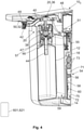
- FIG. 4 a second embodiment of the device 10 2 is shown using a perspective sectional view, which is based on the representation of FIG figure 3 leans against The device 10 2 is in a first configuration.
- FIG. 1 shows the second embodiment of the device 10 2 also based on a perspective sectional view, the device 10 2 being in a second configuration. Both configurations will be discussed later.
- the end figure 4 it can be seen that the device 10 2 is equipped with a drive unit 48 with which the pump plunger 36 can be moved independently into the cavity 14 and which can be designed, for example, as an electric motor. In this case, it is not necessary for the user to press the operating lever 22 with his hand. Consequently, the device 10 2 according to the second embodiment does not have an operating lever 22 .
- the device 10 2 To activate the drive unit 48, the device 10 2 includes a motion sensor 50, which is designed as an ultrasonic sensor 52 or a proximity sensor 52 in the present embodiment.
- the proximity sensor 50 is in the figure 4 only shown in principle and is arranged on a sensor circuit board, not shown in detail here, which is arranged in the cavity above the proximity sensor 50 of the device 10 2 .
- the user must place their hand within the detection range of the motion sensor 50, but without having to touch the device 10 2 .
- a signal is generated by the movement sensor 50 and forwarded to the drive unit 48 .
- the drive unit is activated and a certain quantity of fluid is dispensed via the dispensing opening 42 .
- the mode of operation of the pumping and dosing unit 20 corresponds to that which has been described for the first embodiment of the device 10 1 with the essential difference that the movement of the pump plunger 36 is caused by the drive unit 48 and not as a result of the movement of the actuating lever 22.
- the device 10 2 can be activated without contact according to the second embodiment, there is a risk that particles, in particular pathogens, which have accumulated on the pumping and dosing unit outer surface 30, on the Attach hand of the user and can thereby get into the body of the user.
- the device 10 2 is equipped with a monitoring unit 54 with which device-related and/or user-related data can be recorded and stored.
- the monitoring unit 54 includes a circuit board 71 which is arranged in a further cavity 72 enclosed by the housing 12 .
- the device 102 has a fill level sensor 56 arranged on the circuit board 71, with which the fill level of the fluid in the container 18 can be determined.
- the device 10 2 is equipped with a temperature sensor 58 which is also arranged on the circuit board 71 and with which the temperature in the vicinity of the temperature sensor 58 can be determined.
- the temperature sensor 58 is arranged in such a way that it essentially determines the temperature of the fluid in the container 18 . However, if the temperature in the vicinity of the device 101 falls or rises significantly, as may be the case with a fire, for example, the temperature sensor 58 will also detect this temperature change.
- Both the filling level sensor 56 and the temperature sensor 58 interact with the monitoring unit 54 and supply at least some of the device-related data already mentioned.
- the device 10 2 also has a transmitting and receiving unit 60 which is also arranged on the circuit board 71 .
- This transmission and reception unit 60 data which is on the monitoring unit 54 are stored, are exchanged with external units 62.
- a first external unit 621 is in figure 4 shown, which can be embodied, for example, as a smartphone, as a transponder, as a barcode or the like.
- a user using the device 10 2 can thereby be identified. It is thus possible, for example, to only be able to activate the drive unit 48 when a user has previously been able to be recognized as an authorized user.
- the device 10 2 includes two batteries 73, with which the supply of the drive unit 48 and the electronic components such as the temperature sensor 58 can be guaranteed with electrical energy.
- the device 10 2 has a transmitting and receiving unit 60 with which data can be exchanged wirelessly with external units 621 .
- the device 10 2 also has an Ethernet connection 75 with which the device 10 2 can be connected to a LAN by wire. If the LAN is configured accordingly, the electronic components can also be supplied with electrical energy via the LAN (Power over Ethernet).
- the proximity sensor 50 is on its own, in the figures 4 and 5 mounted sensor board not shown.
- the provision of the sensor circuit board that is spatially separate from the circuit board 71 makes it possible in a simple manner to provide an embodiment of the device 10 2 that can be activated without contact using the proximity sensor 50 on the one hand, but not via the circuit board 71 and consequently the sensors mounted thereon, for example the temperature sensor 58.
- Such an embodiment of the device 10 2 can be useful if documentation is not necessary.
- the figure 5 the device 10 2 in a second configuration. If you compare them figures 4 and 5 , it will be noted that in the second configuration, the pumping and dosing unit 20 has been removed from the housing 12 and another container 18 has been inserted into the cavity 14. This container 18 has its own pumping and dosing unit 66, which in this case is permanently connected to the container. This pumping and dosing unit 66 also includes its own dispensing opening 68.
- the container 18, which in figure 5 is inserted into the cavity 14 also has a significantly lower height than the container that is in figure 4 has been inserted into the cavity.
- a support body 70 is placed on the bearing surface 59 which the container 18 is supported. Alternatively, the supporting body can also be hung in the housing 12 . As a result, the lower height of the container 18 is compensated.
- FIG. 6 a system 64 for monitoring the in the figures 4 and 5 shown device 10 2 is shown based on a basic representation.
- the system 64 comprises the device 10 2 , the already mentioned first external unit 621, a second external unit 622 and a third external unit 623, the third external unit 623 having to be present only optionally.
- the number of devices 10 2 , first external units 621, of the second external units 622 and the third external units 623 can be selected arbitrarily.
- the first external unit 621 can be embodied as a barcode that can be read by the transmitting and receiving unit 60 of the device 10 1 . Consequently, it is not absolutely necessary for the first external unit 621 to have a first transmitting and receiving unit 601, which is the case, for example, when the first external unit 621 is designed as a smartphone or as a transponder.
- the second external unit 622 can be a server of a hospital, a doctor's office or a factory, for example, which can communicate with the device 10 2 for example via a WLAN network and consequently has a second transmitting and receiving unit 602 .
- the second external unit 622 can exchange data with the third external unit 623 , which can also be configured as a server that communicates with a multiplicity of second external units 622 using a third transmission and reception unit 603 .
- the third external unit 633 can also communicate with the first external unit 621 .
- the system 64 can be operated, for example, in the following ways: As mentioned, the level of the fluid in the container 18 can be monitored using the level sensor 56 and the temperature of the fluid in the container 18 and the temperature in the immediate vicinity of the device 10 1 can be monitored using the temperature sensor 58 will. In the event that the liquid level of the fluid in the container 18 falls below a specific value, a corresponding signal can be generated by the second external unit 622 and transmitted to a specific person. This person can, for example, be the owner of the first external unit 621, which is designed as a smartphone. This person can now initiate the replacement of the container, so that it is avoided that the container 18 located in the device 10 2 is completely emptied and thus the device 10 2 cannot be used as intended.
- the second external unit 622 If the temperature detected by the temperature sensor 58 rises to a specific value over a specific period of time, this can be an indication of contamination of the fluid. In turn, the second external unit 622 generates a corresponding signal and sends it to the first external unit 621, so that the person responsible can also arrange for the container located in the device 10 2 to be exchanged. If the temperature measured by the temperature sensor 58 rises to an unusually high value within a very short time, this can be interpreted as an indication of a fire. The second external unit 622 can now trigger a fire alarm. Since the location of the device 10 2 , whose temperature sensor 58 has registered the temperature increase, is known, the source of the fire can be localized.
- this information is stored in the third external unit 623 . If the person used the device 10 2 before the time at which the infection was detected, a corresponding signal can be generated which indicates the need to disinfect the device 10 2 as quickly as possible, for example by autoclaving. Furthermore, other people who used the device 10 2 shortly after the infected person can be informed in order to be able to initiate appropriate countermeasures.
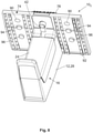
- FIGS figures 7 and 8th a third embodiment of the proposed device 10 3 is shown using perspective illustrations.
- the device 10 3 according to the third embodiment includes all the features of the second embodiment of the device 10 2 and thus builds on this.
- the device 10 3 according to the third embodiment shown in FIGS figures 7 and 8th not visible drive unit 48 on. Only the additional features are referred to below.
- the device 10 3 has a cover plate 74 which is connected to the housing 12, for example by means of a snap-in connection.
- the cover plate 74 can also be manufactured as an integral part of the housing 12 . In figure 7 you look at them Upper side of the cover plate 74.
- the cover plate 74 protrudes beyond the housing 12 to the left and to the right.
- a display 76 is fastened to the cover plate 74, with which user-related data and device-related data or other data can be displayed.
- the display 76 has a display section 78 for this purpose.
- a user identification device 80 is arranged in the display 76, which comprises a readout unit 82 for reading out an RFID transponder 84, which is only shown in principle here.
- the user identification device 80 includes a second camera 86 which is also arranged in the display 76 .
- the display 76 also includes a number of keypads 88, in this case twelve keypads 88, each of the keypads 88 being associated with a specific activity associated with a disinfection process. This will be discussed in more detail later.
- figure 8 shows the device 10 3 according to the third embodiment based on a second perspective view, in which one can look at the underside of the cover plate 74 .
- Two ultrasound sensors 90 are arranged on the underside of the cover plate 74, which can emit ultrasound and detect reflected ultrasound.
- a multiplicity of light sources 92 are arranged in the form of a strip on the underside of the cover plate 74 and can emit ultraviolet radiation.
- these light sources 92 are in the form of LED strips which extend from the front edge to the rear edge of the cover plate 74 .
- UV sensors 94 are provided, which are also attached to the underside of the cover plate 74 and can detect reflected UV rays.
- first cameras 96 are arranged on the underside of the cover plate 74 . Both the ultrasonic sensors 90 and the light sources 92, the UV sensors 94 and the first two cameras 96 interact with the monitoring unit 54, which is not visible here.
- the device 10 3 according to the third embodiment can be operated in the following manner.
- a user for example a hospital employee, who wants to disinfect his hands, holds an assigned RFID transponder 84 in front of the readout unit 82.
- the second camera 86 can instead capture the facial features of the employee, for example.
- the readout unit 82 and the second camera 86 can also be operated in parallel with one another in order to create redundancy. The aim is to identify the employee. If the employee has been successfully identified, corresponding information can be output on the display section 78 of the display 76 . If the identification is unsuccessful, a corresponding error message can be issued.
- the employee can now select one of the key fields 88, which is assigned to the activity that the employee wants to carry out, for example a catheter change. Then the employee holds his hands under the first Camera 96 and/or under the ultrasonic sensor 90. The device 10 3 now checks whether the employee is wearing jewelry such as a ring or has artificial nails. If this is the case, a corresponding message is issued, according to which the applicable regulations have been violated. If the employee does not have artificial nails and does not wear any jewelry, a corresponding OK message is issued and the employee can now move his hands under the delivery opening 42 .
- This movement is from the in figure 8 motion sensor 50, not shown, is registered (see, for example, figures 4 and 5 ), as a result of which the drive unit 48 is activated and a certain quantity of the fluid is dispensed.
- the amount of fluid dispensed can depend on the chosen activity.
- a fluorescent additive is added to the fluid, which becomes visible in interaction with the UV rays emitted by the light sources 92 .
- the employee After the employee has massaged the fluid into the surfaces of his hands, he can already see for himself whether the entire surface of the hand has been wetted by the fluid or whether areas are missing. For this purpose, the user holds his hands under the light sources 92, which have been switched on at the same time as or shortly after the activation of the drive unit 48.
- the device 10 3 can be used to check whether the entire surface of the hand has been wetted by the fluid or whether areas are missing. If the entire surface of the hand is wetted by the fluid, another OK message is issued, which means that hand disinfection has been successfully completed. If areas are missing, the fluid must be massaged in again or additional fluid requested.
- All data logged by the monitoring unit 54 of the device 10 3 during the hand disinfection are transmitted by the transmitting and receiving unit 60 (cf. figures 4 and 5 ) transmitted to the external units 62.
- the external units 62 document that the employee in question has carried out the activity in question after he has disinfected his hands in accordance with regulations.
- the information that the hand disinfection has been successfully completed can also be used to grant the relevant employee access to the patient.
- the external units 62 can interact with a door opener, which only opens the door to the room in which the patient is located after hand disinfection has been successfully completed.
- the steps for hand disinfection described above can also be carried out in a different order.
- additional steps can be provided or steps can be omitted.
Landscapes
- Health & Medical Sciences (AREA)
- Public Health (AREA)
- Epidemiology (AREA)
- Life Sciences & Earth Sciences (AREA)
- Animal Behavior & Ethology (AREA)
- General Health & Medical Sciences (AREA)
- Veterinary Medicine (AREA)
- Chemical & Material Sciences (AREA)
- Chemical Kinetics & Catalysis (AREA)
- General Chemical & Material Sciences (AREA)
- Apparatus For Disinfection Or Sterilisation (AREA)
Applications Claiming Priority (1)
| Application Number | Priority Date | Filing Date | Title |
|---|---|---|---|
| DE102020122427 | 2020-08-27 |
Publications (1)
| Publication Number | Publication Date |
|---|---|
| EP3960049A1 true EP3960049A1 (fr) | 2022-03-02 |
Family
ID=77640328
Family Applications (1)
| Application Number | Title | Priority Date | Filing Date |
|---|---|---|---|
| EP21191561.6A Pending EP3960049A1 (fr) | 2020-08-27 | 2021-08-16 | Dispositif de distribution d'un fluide, en particulier d'un fluide de nettoyage, d'entretien ou de désinfectant pour les mains, ainsi que système de surveillance d'un tel dispositif |
Country Status (3)
| Country | Link |
|---|---|
| US (1) | US11730837B2 (fr) |
| EP (1) | EP3960049A1 (fr) |
| DE (1) | DE102021121250A1 (fr) |
Families Citing this family (8)
| Publication number | Priority date | Publication date | Assignee | Title |
|---|---|---|---|---|
| USD975469S1 (en) * | 2021-02-10 | 2023-01-17 | Huonker Gmbh | Disinfectant dispenser |
| US20220384017A1 (en) * | 2021-05-28 | 2022-12-01 | Cilag Gmbh International | Aggregated network of surgical hubs for efficiency analysis |
| DE102021124969A1 (de) | 2021-09-27 | 2023-03-30 | Schülke & Mayr GmbH | Adaptersystem zum Anordnen eines Fluidbehälters mit verkürztem Auslass in einem herkömmlichen Fluidspender |
| CN114558160B (zh) * | 2022-03-16 | 2023-07-07 | 江苏环亚医用科技集团股份有限公司 | 一种消毒机器人消毒仓用快拆装置 |
| DE202022102408U1 (de) | 2022-05-03 | 2022-05-09 | Huonker Gmbh | Vorrichtung zum Abgeben eines Fluids, insbesondere eines Reinigungs-, Pflege- oder Desinfektionsfluids für Hände |
| USD1052320S1 (en) * | 2022-08-05 | 2024-11-26 | Tradeline B.V. | Water purifier |
| DE102023102885A1 (de) * | 2023-02-07 | 2024-08-08 | Huonker Gmbh | Vorrichtung zum Abgeben eines Fluids, insbesondere eines Reinigungs-, Pflege- oder Desinfektionsfluids für Hände sowie System zum Überwachen einer derartigen Vorrichtung und Verfahren zum Betrieb einer solchen Vorrichtung innerhalb eines derartigen Systems |
| JP1777156S (ja) * | 2024-03-05 | 2024-08-06 | オートディスペンサー |
Citations (7)
| Publication number | Priority date | Publication date | Assignee | Title |
|---|---|---|---|---|
| DE1058272B (de) | 1955-08-27 | 1959-05-27 | Teepack Spezialmaschinen G M B | Balkenwaage zum kontinuierlichen Abwiegen gleicher Schuettgutmengen |
| US5695091A (en) * | 1995-10-25 | 1997-12-09 | The Path-X Corporation | Automated dispenser for disinfectant with proximity sensor |
| US20150199883A1 (en) * | 2014-01-15 | 2015-07-16 | Kaylin Wayne Hartley | Hand Sanitation Dispensing and Tracking Systems and Methods |
| US9700181B1 (en) * | 2016-08-31 | 2017-07-11 | Vi-Jon, Inc. | Dispenser assembly including enclosure with handle |
| US20180364672A1 (en) * | 2017-06-16 | 2018-12-20 | Rajaram Govindarajan KAMATCHI | Intelligent dispenser of disinfectant gel for connection to disinfection habits monitoring system |
| JP2019017672A (ja) * | 2017-07-14 | 2019-02-07 | 花王株式会社 | ディスペンサ |
| EP3650128A1 (fr) | 2018-11-08 | 2020-05-13 | OP-Hygiene IP GmbH | Tube plongeur frangible |
Family Cites Families (2)
| Publication number | Priority date | Publication date | Assignee | Title |
|---|---|---|---|---|
| DE10258272A1 (de) | 2002-12-13 | 2004-07-08 | Schneider, Hartmut J. | Vorrichtung zum Ausbringen von Desinfektions- und Reinigungsmitteln insbesondere für Hände |
| AT511784B1 (de) | 2011-08-02 | 2016-09-15 | Hagleitner Hans Georg | Dosiervorrichtung, insbesondere sanitärspender, und netzwerk zur datenkommunikation |
-
2021
- 2021-08-16 EP EP21191561.6A patent/EP3960049A1/fr active Pending
- 2021-08-16 DE DE102021121250.2A patent/DE102021121250A1/de active Pending
- 2021-08-27 US US17/459,191 patent/US11730837B2/en active Active
Patent Citations (7)
| Publication number | Priority date | Publication date | Assignee | Title |
|---|---|---|---|---|
| DE1058272B (de) | 1955-08-27 | 1959-05-27 | Teepack Spezialmaschinen G M B | Balkenwaage zum kontinuierlichen Abwiegen gleicher Schuettgutmengen |
| US5695091A (en) * | 1995-10-25 | 1997-12-09 | The Path-X Corporation | Automated dispenser for disinfectant with proximity sensor |
| US20150199883A1 (en) * | 2014-01-15 | 2015-07-16 | Kaylin Wayne Hartley | Hand Sanitation Dispensing and Tracking Systems and Methods |
| US9700181B1 (en) * | 2016-08-31 | 2017-07-11 | Vi-Jon, Inc. | Dispenser assembly including enclosure with handle |
| US20180364672A1 (en) * | 2017-06-16 | 2018-12-20 | Rajaram Govindarajan KAMATCHI | Intelligent dispenser of disinfectant gel for connection to disinfection habits monitoring system |
| JP2019017672A (ja) * | 2017-07-14 | 2019-02-07 | 花王株式会社 | ディスペンサ |
| EP3650128A1 (fr) | 2018-11-08 | 2020-05-13 | OP-Hygiene IP GmbH | Tube plongeur frangible |
Also Published As
| Publication number | Publication date |
|---|---|
| DE102021121250A1 (de) | 2022-03-03 |
| US20220062455A1 (en) | 2022-03-03 |
| US11730837B2 (en) | 2023-08-22 |
Similar Documents
| Publication | Publication Date | Title |
|---|---|---|
| EP3960049A1 (fr) | Dispositif de distribution d'un fluide, en particulier d'un fluide de nettoyage, d'entretien ou de désinfectant pour les mains, ainsi que système de surveillance d'un tel dispositif | |
| US8742932B2 (en) | Hand wash and sanitation device | |
| DE69708606T2 (de) | Verfahren und system zur verbesserung der handsauberkeit | |
| EP1989986B1 (fr) | Commande de désinfection par la sélection d'agents pathogènes cibles | |
| US5695091A (en) | Automated dispenser for disinfectant with proximity sensor | |
| EP3118395B1 (fr) | Dispositif de desinfection d'une poignee a actionnement manuel | |
| WO2009033301A1 (fr) | Distributeur de fluide automatique | |
| AU2014290458A1 (en) | Automatic hygiene compliance assistance | |
| CN211253928U (zh) | 一种具有除菌和压缩功能的医疗垃圾回收设备 | |
| DE202017107187U1 (de) | Vorrichtung zum Waschen und Desinfizieren von Händen | |
| EP2561820A1 (fr) | Dispositif d'application de fluide sans contact | |
| EP3185777B1 (fr) | Système et procédé associé permettant de surveiller les efforts de nettoyage et de désinfection de soignants utilisant des stéthoscopes | |
| DE102018115053A1 (de) | Extrakorporale Blutbehandlungsmaschine mit Spender und Verfahren zu deren Benutzung | |
| DE202021104712U1 (de) | Schuhsohlen-Desinfektionsvorrichtung | |
| DE102018000440A1 (de) | Zuverlässig arbeitende leicht bedienbare Vorrichtung zur Überwachung der Desinfektion und Verfahren zum kontrollierten Überwachen derselben | |
| DE102015108779A1 (de) | Reinigungsvorrichtung, insbesondere Desinfektionsvorrichtung für eine Brause | |
| DE102021113667B4 (de) | Flüssigkeitsspender | |
| DE202020103481U1 (de) | Reinigungs- und/oder Desinfektionsvorrichtung | |
| EP2260785B1 (fr) | Dispositif pour l' alimentation en liquides d'un poste de travail médical, en particulier dentaire | |
| DE102023102885A1 (de) | Vorrichtung zum Abgeben eines Fluids, insbesondere eines Reinigungs-, Pflege- oder Desinfektionsfluids für Hände sowie System zum Überwachen einer derartigen Vorrichtung und Verfahren zum Betrieb einer solchen Vorrichtung innerhalb eines derartigen Systems | |
| EP4649858A2 (fr) | Enveloppe protectrice avec un dispositif de désinfection | |
| DE102016120240B3 (de) | Automatischer Medikamentenspender, Medikamentenrad hierfür sowie Verfahren zum Betrieb | |
| WO2000013802A1 (fr) | Dispositif de vaporisation ou flacon vaporisateur dote d'un dispositif de production de signaux | |
| DE202019001419U1 (de) | Tragbares Desinfektionsgerät für Stethoskope aber auch andere Oberflächen,welches am Kittel,Gürtel oder stationär befestigt werden kann und welches mit dem Stethoskop verbunden ist, sodass man dadurch ein Stethoskop ohne Behinderung verwenden kann | |
| DE102004064275B3 (de) | Einrichtung zur Versorgung eines medizinischen bzw. zahnmedizinischen Arbeitsplatzes mit flüssigen Betriebsstoffen |
Legal Events
| Date | Code | Title | Description |
|---|---|---|---|
| PUAI | Public reference made under article 153(3) epc to a published international application that has entered the european phase |
Free format text: ORIGINAL CODE: 0009012 |
|
| STAA | Information on the status of an ep patent application or granted ep patent |
Free format text: STATUS: THE APPLICATION HAS BEEN PUBLISHED |
|
| AK | Designated contracting states |
Kind code of ref document: A1 Designated state(s): AL AT BE BG CH CY CZ DE DK EE ES FI FR GB GR HR HU IE IS IT LI LT LU LV MC MK MT NL NO PL PT RO RS SE SI SK SM TR |
|
| STAA | Information on the status of an ep patent application or granted ep patent |
Free format text: STATUS: REQUEST FOR EXAMINATION WAS MADE |
|
| 17P | Request for examination filed |
Effective date: 20220825 |
|
| RBV | Designated contracting states (corrected) |
Designated state(s): AL AT BE BG CH CY CZ DE DK EE ES FI FR GB GR HR HU IE IS IT LI LT LU LV MC MK MT NL NO PL PT RO RS SE SI SK SM TR |
|
| P01 | Opt-out of the competence of the unified patent court (upc) registered |
Effective date: 20230322 |
|
| STAA | Information on the status of an ep patent application or granted ep patent |
Free format text: STATUS: EXAMINATION IS IN PROGRESS |
|
| 17Q | First examination report despatched |
Effective date: 20240417 |