EP3960318A1 - Presse de nivellement permettant de niveler une pièce et procédé de nivellement d'une pièce - Google Patents
Presse de nivellement permettant de niveler une pièce et procédé de nivellement d'une pièce Download PDFInfo
- Publication number
- EP3960318A1 EP3960318A1 EP20192736.5A EP20192736A EP3960318A1 EP 3960318 A1 EP3960318 A1 EP 3960318A1 EP 20192736 A EP20192736 A EP 20192736A EP 3960318 A1 EP3960318 A1 EP 3960318A1
- Authority
- EP
- European Patent Office
- Prior art keywords
- straightening
- workpiece
- machine control
- plastic deformation
- designed
- Prior art date
- Legal status (The legal status is an assumption and is not a legal conclusion. Google has not performed a legal analysis and makes no representation as to the accuracy of the status listed.)
- Withdrawn
Links
- 238000000034 method Methods 0.000 title claims description 31
- 230000005489 elastic deformation Effects 0.000 claims abstract description 7
- 238000012937 correction Methods 0.000 claims description 26
- 238000006073 displacement reaction Methods 0.000 claims description 14
- 230000009466 transformation Effects 0.000 claims description 5
- 230000006870 function Effects 0.000 description 27
- 230000008569 process Effects 0.000 description 20
- 238000004519 manufacturing process Methods 0.000 description 14
- 238000005259 measurement Methods 0.000 description 5
- 239000000463 material Substances 0.000 description 4
- 238000013461 design Methods 0.000 description 3
- 238000005457 optimization Methods 0.000 description 3
- 239000012530 fluid Substances 0.000 description 2
- 238000003754 machining Methods 0.000 description 2
- 230000006399 behavior Effects 0.000 description 1
- 210000000078 claw Anatomy 0.000 description 1
- 238000010276 construction Methods 0.000 description 1
- 230000008878 coupling Effects 0.000 description 1
- 238000010168 coupling process Methods 0.000 description 1
- 238000005859 coupling reaction Methods 0.000 description 1
- 230000007547 defect Effects 0.000 description 1
- 238000010586 diagram Methods 0.000 description 1
- 238000001914 filtration Methods 0.000 description 1
- 238000010438 heat treatment Methods 0.000 description 1
- 230000007246 mechanism Effects 0.000 description 1
- 230000003287 optical effect Effects 0.000 description 1
- 238000012545 processing Methods 0.000 description 1
- 238000007493 shaping process Methods 0.000 description 1
- 230000003746 surface roughness Effects 0.000 description 1
Images


Classifications
-
- B—PERFORMING OPERATIONS; TRANSPORTING
- B21—MECHANICAL METAL-WORKING WITHOUT ESSENTIALLY REMOVING MATERIAL; PUNCHING METAL
- B21D—WORKING OR PROCESSING OF SHEET METAL OR METAL TUBES, RODS OR PROFILES WITHOUT ESSENTIALLY REMOVING MATERIAL; PUNCHING METAL
- B21D3/00—Straightening or restoring form of metal rods, metal tubes, metal profiles, or specific articles made therefrom, whether or not in combination with sheet metal parts
- B21D3/10—Straightening or restoring form of metal rods, metal tubes, metal profiles, or specific articles made therefrom, whether or not in combination with sheet metal parts between rams and anvils or abutments
Definitions
- the invention relates to a straightening press for straightening a workpiece according to the preamble of claim 1 and a method for straightening a workpiece according to the preamble of claim 11.
- the invention is based on the object of further developing a straightening press of the generic type in such a way that workpieces can be straightened quickly.
- the invention is based on the object of specifying a method of the generic type that enables workpieces to be straightened quickly.
- the straightening press comprises a machine controller, a holder for fixing the workpiece in the straightening press, a measuring unit coupled to the machine controller for determining the dimensional deviation of the workpiece, and a straightening die.
- the straightening die is used to deform the workpiece by a straightening path.
- the straightening path corresponds to the sum of the elastic deformation and the plastic deformation of the workpiece, which are caused by a punch stroke by means of the straightening punch.
- the machine controller is designed in such a way that the machine controller automatically determines the straightening path by calculating the plastic deformation of the workpiece in advance and determining the straightening path as a function of the plastic deformation by the machine controller.
- the straightening path can be determined by the machine control system as a functional function of the plastic deformation. With the execution of a punch stroke, the workpiece is then deformed by the straightening path. Since the straightening path is determined as a function of the plastic deformation, a plastic deformation component can be achieved on the workpiece after a single, but at least after a few punch strokes, by means of which the specified manufacturing tolerances of the workpiece can be achieved. This reduces the number of straightening strokes and thus also the time it takes to straighten a workpiece.
- the target relationship corresponds to a function that describes the dependence of the straightening path on the plastic deformation of the workpiece.
- the function contains several parameters that can be used to adapt the function to the material, geometry, etc., for example.
- deviations can occur when straightening the workpiece between the plastic deformation calculated according to the target relationship and the real, plastic deformation. This deviation is preferably to be determined. If this is determined, counteract the deviation.
- the machine control is preferably designed in such a way that, after a punch stroke, a real plastic deformation of the workpiece is measured by means of the measuring unit.
- the machine control is preferably designed in such a way that the target relationship between the straightening path and the plastic deformation of the workpiece is adapted to the measured, real plastic deformation of the workpiece.
- the parameterization of the target relationship is optimized.
- the parameters are selected in such a way that the actually measured plastic deformations are also reflected by the target relationship.
- Such parameterization preferably takes place after each punch stroke on the basis of each newly measured value for the real plastic deformation.
- the target relationship can also be optimized only after a complete straightening process on the basis of a plurality of measured values.
- the machine control is thus designed to be self-learning.
- the target relationship between straightening distance and plastic deformation is optimized with each workpiece to be straightened.
- the machine control is designed in such a way that the dimensional accuracy of the workpiece is determined via the measuring unit.
- the dimensional accuracy at each straightening point is preferably determined by means of the measuring unit.
- the machine control is preferably designed in such a way that the data recorded by the measuring unit are filtered by the machine control. As a result, the data are cleaned of surface roughness or other form errors that are not taken into account when straightening a workpiece.
- the machine control is designed in such a way that a correction value is determined on the basis of the data recorded by the measuring unit, in particular the filtered data, by which the workpiece is to be plastically deformed. If the workpiece is adjusted by the correction value, it is within the predetermined manufacturing tolerance.
- the machine control is preferably designed in such a way that the necessary plastic deformation at each straightening point is calculated as a function of all correction values determined for each straightening point. If a workpiece is straightened at only one straightening point, the correction value determined corresponds to the necessary plastic deformation at the corresponding straightening point. If the workpiece is straightened at several straightening points, the plastic deformation of a workpiece at one straightening point can affect the plastic deformation of the workpiece at another straightening point. Accordingly, if there are several straightening points, the necessary plastic deformation to be actively generated is usually lower than the correction value of the corresponding straightening point.
- the straightening press is designed for straightening long goods, in particular round parts and/or profiles, with the measuring unit comprising a displacement sensor for each straightening point.
- the machine control is preferably designed in such a way that, in the case of round parts, the data recorded by means of the measuring unit are filtered and the correction values are determined by means of a Fourier transformation. In the case of round parts, the use of the Fourier transformation allows the maximum deviation to be determined at a corresponding angle of rotation of the round part.
- the method according to the invention for straightening a workpiece with a straightening press comprises the following steps: The workpiece is fixed in the straightening press. The dimensional deviation of the workpiece is then determined using the measuring unit. The straightening path is then automatically determined by means of the machine control, in that the machine control calculates the plastic deformation of the workpiece in advance and determines the straightening path as a function of the plastic deformation.
- the straightening press 1 is used for straightening workpieces 14.
- the straightening press 1 is used for straightening workpieces 14.
- induced internal stresses can lead to unwanted distortion of the workpiece, for example.
- the workpiece 14 is no longer dimensionally accurate and is therefore outside the manufacturing tolerance 47 to be maintained during machining (see Figures 8 to 11 ).
- the straightening press 1 is used for the plastic deformation of a workpiece 14, the dimensional accuracy of which is again within the specified manufacturing tolerances 47 in the straightened state.
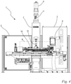
- the straightening press 1 shown has a press table 6 for supporting a workpiece 14 .
- the straightening press 1 also includes an operator terminal 4, which acts as an interface between an operator 3 (see 6 ) and the straightening press 1 is used.
- the straightening press 1 includes a machine control 2, via which the actuators, sensors, etc. of the straightening press 1 are controlled.
- the straightening press 1 has a housing 7 .
- a safety wall 5 connects to the housing 7 .
- the safety wall 5 is arranged in such a way that it at least partially encloses the press bed 6 and as a result only limited access to the straightening press 1 is made possible.
- the design of the safety walls 5 can be individually adapted to the needs of the operator 3 .
- As in 2 shown is operator terminal 4 with machine control 2 connected via a data link 8.
- the data connection 8 is in the form of a cable connection. It can also be expedient to provide a wireless connection, for example via Bluetooth, wireless LAN, etc.
- the straightening press 1 comprises a straightening die 10 with a longitudinal axis 12.
- the straightening die 10 can be moved translationally in the direction of its longitudinal axis 12.
- the direction of the longitudinal axis 12 of the straightening die 10 corresponds to the direction of the z-axis of the 2 shown coordinate system.
- the straightening die 10 can thus be moved in the direction of the z-axis.
- the straightening die 10 is driven by a drive motor 9 in order to carry out the translatory movement.
- the drive motor 9 is designed as an electric motor in the exemplary embodiment.
- the drive motor 9 drives a spindle drive which is coupled to the straightening die 10 and is not shown in detail in the drawing.
- the spindle drive and the drive motor 9 are connected via a clutch 11, which is designed as a claw clutch in the present embodiment. Alternatively, other types of couplings can also be useful.
- the rotational movement of the drive motor 9 is transferred into a translational movement of the straightening die 10 via the spindle drive.
- the straightening press 1 is designed as a C-frame press in the present embodiment. It can be expedient to design the straightening press 1 according to the invention as a portal frame straightening press. Other frame types can also be useful. Since the straightening die 10 can only be moved in the direction of the z-axis, the press table 6 is designed as a movable press table. According to the exemplary embodiment, the straightening press 1 is designed as a straightening press for round parts. Accordingly, the press table 6 can only be moved in the direction of the x-axis. The direction of the x-axis corresponds to the direction of the longitudinal axis of the workpieces clamped on the press table 6 .
- the press table 6 In particular for straightening presses for straightening flat parts, it is expedient to design the press table 6 so that it can also be moved in the direction of the y-axis.
- the press table 6 can also be designed as a rigid press table. So he is Press table cannot be moved.
- the straightening die 10 is designed to be movable in the corresponding spatial axes.
- the straightening press 1 comprises a table top 25 which is part of the press table 6 .
- the tabletop 25 can be moved in the direction of the x-axis.
- the tabletop 25 is motor-driven via a chain drive.
- the drive unit provided for moving the table top 25 is controlled via the machine control 2 .
- the table top 25 can be moved automatically during the straightening process and the workpiece 14 arranged on the table top 25 can be continuously aligned with respect to the straightening die 10 .
- the straightening press 1 comprises a workpiece holder 15, which serves to receive and fix the workpiece 14 to be straightened.
- the workpiece holder 15 is arranged on the table top 25 .
- the workpiece holder 15 comprises a first holder unit 16 and a second holder unit 17 spaced apart from the first holder unit 16. If the workpiece 14 is clamped in the workpiece holder 15, it is held at its ends between the first holder unit 16 and the second holder unit 17.
- Each of the two receiving units 16, 17 includes a tensioning element 18 which is detachably fastened in a carrier 19 of the receiving unit 16, 17.
- the clamping element 18 is interchangeable.
- a corresponding clamping element 18 can be selected and mounted on the carrier 19.
- the workpiece 14 rests at its ends on the clamping elements 18 of the receiving units 16, 17.
- the first receiving unit 16 and the second receiving unit 17 each have a longitudinal axis 20 aligned coaxially with one another, the longitudinal axis 20 running parallel to the x-axis.
- the first accommodating unit 16 and the second accommodating unit 17 are arranged on the table top 25 such that they can be moved relative to one another in the direction of the x-axis.
- the clamping elements 18 are driven to rotate about the longitudinal axis 20 .
- the workpiece 14 can be rotated so that the workpiece 14 can be aligned with respect to the straightening die 10 with respect to a predetermined straightening point 38, 38' (see Figures 8 to 11 ) can be done.
- the straightening press 1 comprises three straightening supports 21 which are arranged on the tabletop 25 in the direction of the x-axis so that they can be moved in relation to one another.
- the straightening supports 21 serve as counter bearings for the workpiece 14 during the straightening process. If, during straightening, the workpiece 14 is pressed by the straightening die 10 in the direction of the z-axis towards the press bed 6 , the workpiece 14 comes to rest on the straightening supports 21 . In the process, a deformation of the workpiece 14 occurs between the push-pull supports 21 serving as counter bearings.
- a prop 21 includes a prop support 22 which is detachably formed on a base body of the prop 21 .
- the support supports 22 can thus also be adapted to the geometry of the workpiece, in particular to that of the alignment points 38, 38'.
- a quick-release fastener 23 is provided on the push-pull supports 21, which provides a fixation of the push-pull supports 21, as a result of which the push-pull supports are blocked from being displaced along the x-axis.
- the props can be shifted by hand along the x-axis on the press table 25 in order to adjust the predetermined support points of the workpiece 14.
- a lifting element 24 is provided on the pushrods 21, which enables an ejection of the workpiece 14 in the direction of the z-axis by means of a fluid mechanism. If the lifting element 24 is actuated, this moves in the direction of z-axis away from the press table 25 and thereby raises the workpiece 14. As a result, the workpiece can be removed from the straightening press 1 more easily.
- the fluid mechanics are designed as pneumatic mechanics. Alternatively, it can also be expedient to provide hydraulic mechanics for the lifting element 24 .
- the straightening die 10 comprises a stamp attachment 13 which is held on the base body of the straightening die 10 .
- the stamp attachment 13 is detachably fixed to the base body of the straightening stamp 10 . Accordingly, the stamp attachment 13 is interchangeable. In this way, the stamp attachment 13 can be adapted to the geometry of the workpiece 14 .
- the straightening die 10 in the exemplary embodiment includes a force sensor 27 which is part of the measuring unit 26 .
- the machine controller 2 uses the signal from the force sensor 27 to recognize when the straightening die 10 is acting on the workpiece 14 . This makes it possible to record the exact straightening path of the straightening die 10 .
- the straightening path is basically the path of the straightening die 10 by which the straightening die 10 deforms the workpiece 14 .
- This overall deformation is in turn composed of an elastic deformation of the workpiece 14 and a plastic deformation of the workpiece 14.
- the machine controller 2 takes the movement of the straightening punch 10 in the direction of the z-axis from the point in time when the straightening punch 10 comes into contact with the workpiece 14 up to the stroke end of the straightening die 10.
- the end of the stroke of the straightening die 10 corresponds to the reversal point of the straightening die 10.
- the measuring unit 26 of the straightening press 1 also includes three displacement sensors 28.
- the number of path sensors 28 should preferably be adapted to the maximum number of alignment points 38, 38' of a workpiece 14. So if a workpiece 14 is to be straightened at three straightening points 38, 38' in a straightening process, a displacement sensor 28 can be provided at each of these three straightening points 38, 38' in order to measure the dimensional deviation of the workpiece 14 at the straightening point 38, 38'. This can without adjusting the displacement sensors 28, a straightening process on the workpiece 14 can take place automatically.
- the displacement sensors 28 are designed as tactile sensors in the exemplary embodiment. However, it can also be useful to provide optical sensors or the like.
- a displacement sensor 28 can be adjusted in the direction of the x-axis and can be fixed in place by a quick-release fastener 23 .
- the displacement sensor 28 includes a feeler rod 29, at the end of which a contact element 30 is formed.
- the contact element 30 of the feeler rod 29 makes contact with the workpiece 14 .
- Feeler rod 29 and clamping lever 31 are preferably formed in one piece and are pivotably mounted via a joint.
- a stop 34 is formed on the clamping lever 31 and is clamped against a holding leg 36 of the displacement sensor 28 via a return spring 35 .
- the displacement sensor 28 includes a measuring rod 32 which is pressed against the tensioning lever 31 by a tensioning spring 33 . If the feeler rod 29 is deflected when measuring the return accuracy of the round part, the clamping lever 31 is also deflected. The measuring rod 32 remains in contact with the tensioning lever 31, which is biased by the tension spring 33, as a result of which the measuring rod 32 is displaced along its longitudinal axis. This movement of the measuring rod 32 is detected by a corresponding sensor element, which is not shown in detail in the drawing, and is sent to the machine control 2 . If the straightening press 1 is designed for straightening flat goods or the like, the displacement sensor 28 is designed in such a way that it measures the deformation of the flat goods in the direction of the z-axis. Of course, concentricity cannot then be measured.
- the props 21 are adjusted manually by the operator.
- the push-pull supports 21 can be motor-driven along the x-axis and to be positioned automatically, controlled by the machine controller 2, without the intervention of the operator 3.
- the dimensional accuracy of the workpiece 14 is determined at the alignment point 38, 38' by means of the measuring unit 26.
- the workpiece 14 is a flat part, only the deviation from the desired geometry of the workpiece 14 in the direction of the z-axis is measured at the alignment point 38, 38'. In the present embodiment, it is a round part.
- a displacement sensor 28 is placed on the workpiece 14 at each alignment point 38, 38'. The workpiece 14 is then rotated by at least 360° about the x-axis via the workpiece holder 15 . The concentricity of the workpiece 14 is measured at each alignment point 38, 38' by means of the displacement sensors 28. The data determined are forwarded to the machine control 2 .
- a correction value 45 is to be determined from the recorded measurement data, by which the geometry of the workpiece 14 is to be corrected in order to lie within the specified manufacturing tolerances 47 .
- the correction value 45 corresponds to the plastic deformation component to be applied within a straightening process at a single straightening point 38, 38'. Are for the straightening process If several alignment points 38, 38' are provided, a correction value 45 must be determined for each alignment point 38, 38'.
- the recorded measurement data must first be processed. The processing of the measurement data recorded includes filtering, in which the data are cleaned of disturbances that should remain unconsidered during straightening.
- These interference variables can be cleaned up by means of conventional filters, for example a Gaussian filter, preferably by means of a Fourier transformation for round parts.
- the processed, recorded data can then be further processed using the machine control 2 .
- the data obtained are compared with the target geometry of the workpiece 14 .
- the deviation of the target geometry from the real measurement data is calculated for each alignment point 38, 38' on the workpiece 14.
- the deviation from the target geometry at the straightening points 38, 38' corresponds to the value of the necessary plastic deformation 46 at the straightening points 38, 38' by which the workpiece 14 to achieve the specified manufacturing tolerance 47 at the straightening points 38, 38' the entire straightening process of the workpiece 14 has to be deformed.
- the manufacturing tolerance 47 results from an upper tolerance threshold 48 and a lower tolerance threshold 49.
- a separate correction value 45 must then be determined for each straightening point 38, 38', as a result of which the workpiece 14 lies within the manufacturing tolerance 47 at all straightening points 38, 38' after the straightening process has taken place. Since the deformations at the individual straightening points 38, 38' influence each other, the deviation, ie the necessary plastic deformation 46, of individual straightening points 38, 38' relative to the target geometry can be greater than the correction value 45 to be made for the corresponding straightening points 38, 38'. Will as in 9 If the workpiece 14 is plastically deformed at the first straightening point 38 by a correction value 45, the workpiece 14 at this first straightening point 38 is not yet within the manufacturing tolerance 47 ( 10 ).
- the workpiece 14 is deformed at its first straightening point 38, but has, as in 10 shown, two elevations on which the workpiece 14 is also to be directed. Accordingly, the workpiece 14 is deformed by a correction value 45 at a second straightening point 38'. Finally, the workpiece 14 is preferably deformed at a third straightening point, not shown. As in 11 shown, the workpiece 14 is only after the completion of the straightening process at all straightening points 38 within the specified manufacturing tolerance 47.
- the number of straightening points 38 required should be selected according to the complexity of the workpiece 14. If the complexity of the workpiece 14 increases, several straightening points 38, 38' are required in order to straighten the workpiece 14.
- the correction values 45 at each alignment point 38, 38' are determined using a system of equations. If a round part is straightened, the concentricity is recorded, after which the system of equations can be set up and solved, preferably via a Fourier transformation. Based on this method step, it is now known by which correction value 45 the workpiece 14 or by which plastic deformation the workpiece 14 must be deformed at the respective straightening points 38 for the individual straightening processes per straightening point 38 .
- the directional path of the straightening die 10 is to be determined in a next method step.
- the difficulty in determining the straightening path is that the straightening path does not correspond to the plastic deformation of the workpiece 14 at the straightening point 38, 38'. Rather, the straightening path corresponds to the temporary overall deformation of the workpiece 14 at the straightening point 38, 38', which in turn an elastic deformation component and a plastic deformation component. If the straightening die moves upwards and releases the workpiece 14, the load on the workpiece 14 is relieved, as a result of which it springs back by the amount of elastic deformation. The workpiece 14 remains deformed only by the plastic deformation amount, whereby the value of the plastic deformation is smaller than that of the straightening path.
- the target relationship 55 corresponds to a function that describes the dependence of the straightening path on the plastic deformation of the workpiece 14 .
- the function is in 12 shown graphically as a curve, with the standard path being plotted on the vertical axis and the elastic deformation component on the right-hand axis.
- the function value corresponds to the straightening path, ie the total deformation at the respective straightening point 38.
- the variable x corresponds to the plastic deformation.
- the function contains a number of parameters a, b, c, by means of which the function is adapted to the properties of the workpiece 14, such as the material, the geometry and the like.
- the determined correction value 45 is used as the plastic deformation component and entered for the variable x.
- the function value and thus the straightening path of the straightening die 10 are determined via the function.
- the workpiece 14 is about the desired Correction value 45 deformed. This significantly reduces the time required for the straightening process.
- the workpiece geometry is measured again after each punch stroke and the plastic deformation caused by the punch stroke is determined. If this plastic deformation corresponds to the predetermined correction value 45, then the target relationship 55 maps the real deformation behavior of the workpiece 14 as a function of the guide path with a sufficient tolerance. If there are deviations between the plastic deformation and the correction value 45, the target relationship 55 between the guide path and the plastic deformation must be adjusted.
- the target relationship 55 is adjusted on the basis of measured values 50', 50". If the measured values 50', 50" deviate from the original target relationship 55, the target relationship 55 is adjusted. Accordingly, the parameters of the above-mentioned function, taking into account the additionally obtained measured values 50', 50". As an example of a diagrammatic optimization, the dotted measured values 50" cause the new, dotted target relationship 55" after an optimization of the parameters.
- the cross-shaped measured values 50' result in a new target relationship 55' shown in dashed lines.
- the optimization of the parameters causes a more realistic prediction of the plastic deformation when the guide path is selected. Thus, with each measurement of the workpiece geometry, the function is newly parameterized and the predictability of the function is optimized.
- Such functions can not only be transferred to workpieces of the same construction, but can also be applied to workpieces of different types. Taking into account generally applicable laws, differences in the materials or geometry can be taken into account, which means that predictions with regard to the plastic deformation of different workpieces are already permissible with a parameterized function.
- Such target relationships or functions can be parameterized and optimized using a large number of straightening processes.
- the function can then be parameterized using the measured values. This ensures that the function is highly meaningful even after the first learning process.
- the workpiece 14 is deformed at a first straightening point 38 in such a way that the correction value 45 is reached, the straightening path is determined, as described above, at the next straightening point 38'. As soon as the workpiece 14 has been deformed in such a way that all correction values 45 of the corresponding straightening points 38 have been achieved, the straightening process is complete.
Landscapes
- Engineering & Computer Science (AREA)
- Mechanical Engineering (AREA)
- Straightening Metal Sheet-Like Bodies (AREA)
Priority Applications (1)
| Application Number | Priority Date | Filing Date | Title |
|---|---|---|---|
| EP20192736.5A EP3960318A1 (fr) | 2020-08-25 | 2020-08-25 | Presse de nivellement permettant de niveler une pièce et procédé de nivellement d'une pièce |
Applications Claiming Priority (1)
| Application Number | Priority Date | Filing Date | Title |
|---|---|---|---|
| EP20192736.5A EP3960318A1 (fr) | 2020-08-25 | 2020-08-25 | Presse de nivellement permettant de niveler une pièce et procédé de nivellement d'une pièce |
Publications (1)
| Publication Number | Publication Date |
|---|---|
| EP3960318A1 true EP3960318A1 (fr) | 2022-03-02 |
Family
ID=72242945
Family Applications (1)
| Application Number | Title | Priority Date | Filing Date |
|---|---|---|---|
| EP20192736.5A Withdrawn EP3960318A1 (fr) | 2020-08-25 | 2020-08-25 | Presse de nivellement permettant de niveler une pièce et procédé de nivellement d'une pièce |
Country Status (1)
| Country | Link |
|---|---|
| EP (1) | EP3960318A1 (fr) |
Cited By (2)
| Publication number | Priority date | Publication date | Assignee | Title |
|---|---|---|---|---|
| US20230297063A1 (en) * | 2022-03-18 | 2023-09-21 | Promess, Inc. | Method, system, and apparatus for forming a workpiece |
| DE102024209294A1 (de) * | 2024-09-26 | 2026-03-26 | Volkswagen Aktiengesellschaft | Verfahren zur Formkorrektur einer Baugruppe |
Citations (6)
| Publication number | Priority date | Publication date | Assignee | Title |
|---|---|---|---|---|
| CH611539A5 (en) * | 1976-05-20 | 1979-06-15 | L C A Engineering Ag | Process and apparatus for straightening a workpiece consisting of elastically deformable material |
| DE3322777A1 (de) * | 1983-06-24 | 1985-01-03 | Fraunhofer-Gesellschaft zur Förderung der angewandten Forschung e.V., 8000 München | Verfahren zum richtenden umformen, insbesondere biegerichten und/oder torsionsrichten, von werkstuecken |
| JPH04200822A (ja) * | 1990-11-30 | 1992-07-21 | Hitachi Ltd | 修正寸法算出方法及び寸法調整方法並びにvtrヘッドの製造方法 |
| JP2002059216A (ja) * | 2000-05-29 | 2002-02-26 | Minebea Co Ltd | 平面体の歪矯正方法及び装置 |
| WO2003097265A1 (fr) * | 2002-05-20 | 2003-11-27 | Uk-Tech Ltd. | Procede et systeme de verification/correction d'un composant |
| US20180161840A1 (en) * | 2015-09-28 | 2018-06-14 | Bayerische Motoren Werke Aktiengesellschaft | Method for Straightening a Distortion of a Component by Way of a Straightening Device, and Straightening Device |
-
2020
- 2020-08-25 EP EP20192736.5A patent/EP3960318A1/fr not_active Withdrawn
Patent Citations (6)
| Publication number | Priority date | Publication date | Assignee | Title |
|---|---|---|---|---|
| CH611539A5 (en) * | 1976-05-20 | 1979-06-15 | L C A Engineering Ag | Process and apparatus for straightening a workpiece consisting of elastically deformable material |
| DE3322777A1 (de) * | 1983-06-24 | 1985-01-03 | Fraunhofer-Gesellschaft zur Förderung der angewandten Forschung e.V., 8000 München | Verfahren zum richtenden umformen, insbesondere biegerichten und/oder torsionsrichten, von werkstuecken |
| JPH04200822A (ja) * | 1990-11-30 | 1992-07-21 | Hitachi Ltd | 修正寸法算出方法及び寸法調整方法並びにvtrヘッドの製造方法 |
| JP2002059216A (ja) * | 2000-05-29 | 2002-02-26 | Minebea Co Ltd | 平面体の歪矯正方法及び装置 |
| WO2003097265A1 (fr) * | 2002-05-20 | 2003-11-27 | Uk-Tech Ltd. | Procede et systeme de verification/correction d'un composant |
| US20180161840A1 (en) * | 2015-09-28 | 2018-06-14 | Bayerische Motoren Werke Aktiengesellschaft | Method for Straightening a Distortion of a Component by Way of a Straightening Device, and Straightening Device |
Cited By (2)
| Publication number | Priority date | Publication date | Assignee | Title |
|---|---|---|---|---|
| US20230297063A1 (en) * | 2022-03-18 | 2023-09-21 | Promess, Inc. | Method, system, and apparatus for forming a workpiece |
| DE102024209294A1 (de) * | 2024-09-26 | 2026-03-26 | Volkswagen Aktiengesellschaft | Verfahren zur Formkorrektur einer Baugruppe |
Similar Documents
| Publication | Publication Date | Title |
|---|---|---|
| DE3781887T2 (de) | Adaptivsteuerungssystem fuer hydraulische abkantpresse. | |
| AT402372B (de) | Blechbiegemaschine mit einem manipulator und einer detektorvorrichtung für die lage des werkstückes | |
| DE3883356T2 (de) | Verfahren zum automatischen Zusammenbau von Fahrzeugen und Einrichtung der Fertigungsstrasse. | |
| DE69520944T2 (de) | Biegepresse. | |
| DE69431930T2 (de) | Vorrichtung zum automatisch Wechseln von Werkzeugen in einer Biegevorrichtung | |
| WO2007128444A1 (fr) | ProcÉdÉ et dispositif pour palper un point sur la surface d'une piÈce | |
| AT516761B1 (de) | Verfahren und Anlage für das Richten von metallischen Teilen | |
| DE102018000022A1 (de) | Verfahren zum Richten von Rundlauf- oder Gradheitsfehlern an langgestreckten Werkstücken, sowie hierfür Messvorrichtung, Richtmaschine und Richtsystem | |
| EP3960318A1 (fr) | Presse de nivellement permettant de niveler une pièce et procédé de nivellement d'une pièce | |
| DE69011077T2 (de) | Regelanordnung für abkantpresse. | |
| EP2177291B1 (fr) | Procédé de découpe et/ou formage de pièces | |
| WO2016037208A1 (fr) | Presse plieuse | |
| DE102005027640B4 (de) | Verfahren und Vorrichtung zum automatischen Biegerichten länglicher Werkstücke | |
| WO2018145718A1 (fr) | Dispositif de façonnage et d'emboutissage équipé de manière modulaire d'un mécanisme d'entraînement à moteur et procédé | |
| AT518560B1 (de) | Biegebalken für eine Schwenkbiegemaschine | |
| EP0613573B1 (fr) | Procede permettant de verifier la precision d'une machine a commande numerique | |
| AT523360B1 (de) | Biegemaschine und Kontrolleinrichtung | |
| DE112017004487T5 (de) | Maschine und Verfahren zum Fluidstrahlschneiden | |
| DE102022131427A1 (de) | Verfahren und Vorrichtung zum Erkennen einer Nachlaufkante bei einem Blechteil nach einem Tiefziehvorgang | |
| DE102022100935A1 (de) | Verfahren und Stanzmaschine zum Ermitteln einer Stempelaufsetzposition eines Stempels der Stanzmaschine | |
| EP4186609A1 (fr) | Dispositif de pliage et de mesure et procédé de fonctionnement d'un dispositif de pliage et de mesure | |
| DE4323992A1 (de) | Verfahren zur Überprüfung der Arbeitsgenauigkeit einer NC-Maschine | |
| AT520649B1 (de) | Verfahren mit einer Fertigungseinrichtung zum Umformen von Blech | |
| EP1635972A1 (fr) | Procede et dispositif pour travailler des pieces par formage | |
| DE102005038470A1 (de) | Umformwerkzeug und Verfahren zum Positionieren des Umformwerkzeugs |
Legal Events
| Date | Code | Title | Description |
|---|---|---|---|
| PUAI | Public reference made under article 153(3) epc to a published international application that has entered the european phase |
Free format text: ORIGINAL CODE: 0009012 |
|
| STAA | Information on the status of an ep patent application or granted ep patent |
Free format text: STATUS: THE APPLICATION HAS BEEN PUBLISHED |
|
| AK | Designated contracting states |
Kind code of ref document: A1 Designated state(s): AL AT BE BG CH CY CZ DE DK EE ES FI FR GB GR HR HU IE IS IT LI LT LU LV MC MK MT NL NO PL PT RO RS SE SI SK SM TR |
|
| STAA | Information on the status of an ep patent application or granted ep patent |
Free format text: STATUS: THE APPLICATION IS DEEMED TO BE WITHDRAWN |
|
| 18D | Application deemed to be withdrawn |
Effective date: 20220903 |