EP3960321B1 - Pressformverfahren - Google Patents
Pressformverfahren Download PDFInfo
- Publication number
- EP3960321B1 EP3960321B1 EP19926276.7A EP19926276A EP3960321B1 EP 3960321 B1 EP3960321 B1 EP 3960321B1 EP 19926276 A EP19926276 A EP 19926276A EP 3960321 B1 EP3960321 B1 EP 3960321B1
- Authority
- EP
- European Patent Office
- Prior art keywords
- side wall
- press
- web
- twisted
- wall portion
- Prior art date
- Legal status (The legal status is an assumption and is not a legal conclusion. Google has not performed a legal analysis and makes no representation as to the accuracy of the status listed.)
- Active
Links
Images






Classifications
-
- B—PERFORMING OPERATIONS; TRANSPORTING
- B21—MECHANICAL METAL-WORKING WITHOUT ESSENTIALLY REMOVING MATERIAL; PUNCHING METAL
- B21D—WORKING OR PROCESSING OF SHEET METAL OR METAL TUBES, RODS OR PROFILES WITHOUT ESSENTIALLY REMOVING MATERIAL; PUNCHING METAL
- B21D22/00—Shaping without cutting, by stamping, spinning, or deep-drawing
- B21D22/20—Deep-drawing
- B21D22/22—Deep-drawing with devices for holding the edge of the blanks
-
- B—PERFORMING OPERATIONS; TRANSPORTING
- B21—MECHANICAL METAL-WORKING WITHOUT ESSENTIALLY REMOVING MATERIAL; PUNCHING METAL
- B21D—WORKING OR PROCESSING OF SHEET METAL OR METAL TUBES, RODS OR PROFILES WITHOUT ESSENTIALLY REMOVING MATERIAL; PUNCHING METAL
- B21D22/00—Shaping without cutting, by stamping, spinning, or deep-drawing
- B21D22/20—Deep-drawing
- B21D22/26—Deep-drawing for making peculiarly, e.g. irregularly, shaped articles
-
- B—PERFORMING OPERATIONS; TRANSPORTING
- B21—MECHANICAL METAL-WORKING WITHOUT ESSENTIALLY REMOVING MATERIAL; PUNCHING METAL
- B21D—WORKING OR PROCESSING OF SHEET METAL OR METAL TUBES, RODS OR PROFILES WITHOUT ESSENTIALLY REMOVING MATERIAL; PUNCHING METAL
- B21D22/00—Shaping without cutting, by stamping, spinning, or deep-drawing
- B21D22/02—Stamping using rigid devices or tools
-
- B—PERFORMING OPERATIONS; TRANSPORTING
- B21—MECHANICAL METAL-WORKING WITHOUT ESSENTIALLY REMOVING MATERIAL; PUNCHING METAL
- B21D—WORKING OR PROCESSING OF SHEET METAL OR METAL TUBES, RODS OR PROFILES WITHOUT ESSENTIALLY REMOVING MATERIAL; PUNCHING METAL
- B21D22/00—Shaping without cutting, by stamping, spinning, or deep-drawing
- B21D22/20—Deep-drawing
-
- B—PERFORMING OPERATIONS; TRANSPORTING
- B21—MECHANICAL METAL-WORKING WITHOUT ESSENTIALLY REMOVING MATERIAL; PUNCHING METAL
- B21D—WORKING OR PROCESSING OF SHEET METAL OR METAL TUBES, RODS OR PROFILES WITHOUT ESSENTIALLY REMOVING MATERIAL; PUNCHING METAL
- B21D53/00—Making other particular articles
- B21D53/88—Making other particular articles other parts for vehicles, e.g. cowlings, mudguards
-
- B—PERFORMING OPERATIONS; TRANSPORTING
- B29—WORKING OF PLASTICS; WORKING OF SUBSTANCES IN A PLASTIC STATE IN GENERAL
- B29C—SHAPING OR JOINING OF PLASTICS; SHAPING OF MATERIAL IN A PLASTIC STATE, NOT OTHERWISE PROVIDED FOR; AFTER-TREATMENT OF THE SHAPED PRODUCTS, e.g. REPAIRING
- B29C43/00—Compression moulding, i.e. applying external pressure to flow the moulding material; Apparatus therefor
- B29C43/02—Compression moulding, i.e. applying external pressure to flow the moulding material; Apparatus therefor of articles of definite length, i.e. discrete articles
Definitions
- the present invention relates to a press forming method, and in particular to a press forming method for a press-formed product that has a hat-shaped cross section with a web portion, side wall portions, and flange portions, and that is convexly curved in the height direction along the longitudinal direction in side view.
- Press forming is a method of processing a metal sheet, such as a steel sheet, by clamping the metal sheet with a die of press forming and transferring the shape of the die.
- a metal sheet such as a steel sheet
- many automotive parts are manufactured by press forming.
- high-strength steel sheets for body parts in view of weight reduction of automotive bodies.
- elongation tends to decrease, and forming defects such as fractures and wrinkles often occur in the press forming of high-strength steel sheets, causing problems.
- curved parts having a steeply curved shape such as front side members and rear side members, tend to have fractures and wrinkles when manufactured by press forming. These members are thus considered to be parts difficult to form.
- automobile and parts manufacturers have been studying the application of high-strength steel sheets in the manufacture of such curved parts in order to further reduce the weight of automotive bodies, and an issue is how to perform press forming while preventing fractures and wrinkles.
- Patent Literature 1 discloses a technique for avoiding wrinkles in a punch bottom and fractures in a flange in press forming of an L-shaped part that is curved in top view, by using a forming load to form the flange and a side wall and sliding the material at the punch bottom.
- Patent Literature 2 provides a method of preventing out-of-plane deformation and suppressing wrinkles of parts that are curved in the vertical direction by performing drawing forming while applying pressure to the punch bottom of a blank in the thickness direction with a pad.
- Patent Literature 3 discloses a technique for suppressing the occurrence of wrinkles in a flange portion in press forming of a curved press part with a hat-shaped cross section curved in the longitudinal direction, by preforming a folding portion at an end portion of a blank material in the width direction and then press-forming the curved press part while leaving the folding portion.
- Patent Literature 4 discloses a technique for suppressing the occurrence of wrinkles in a material formed section when press-forming, in one process, a material into a shape that has a curvature when an end portion of the material is viewed in plan view and that has a flange surface below a side wall surface in side view, by adding a convex bead to the side wall surface and a concave bead to the flange surface directly below the concave bead.
- EP 3437751 A1 discloses a method for producing a press-formed product having a hat-shaped cross section and being curved convexly and concavely curved in the longitudinal direction. The method involves producing an intermediate product with a twisted side wall portion wherein the angle between a side wall portion and a web portion is larger at an end portion than at a center portion in the longitudinal direction.
- Patent Literature 1 has limited applicability to parts that have a shape such as a mounted surface at the punch bottom or that have a closed shape such as a bag shape, because the material cannot be moved significantly.
- Patent Literature 2 a blank holder and pad are used at the same time for forming, and when a formed product is removed from a die, if the blank holder or pad remains under pressure, it will crush the formed product. Thus, a locking structure is necessary to stop movement.
- press machines equipped with this mechanism are not common, the technique lacks versatility.
- Patent Literature 4 The technique disclosed in Patent Literature 4 is press forming in one process, and has the problem that the bead added to prevent wrinkle occurrence and fracturing remains as it is.
- the present invention has been made in order to solve the above problems, and an object of the present invention is to provide a press forming method that can press-form, into a favorable shape, a press-formed product that has a hat-shaped cross section with a web portion, side wall portions, and flange portions, and that is convexly curved in the height direction along the longitudinal direction, while suppressing fractures and wrinkles.
- the invention provides a press forming method as defined in claim 1.
- shear deformation can be generated in the twisted side wall portion, and the occurrence of fractures and wrinkles is suppressed, enabling the press-formed product to be press-formed into a favorable shape.
- the following explains a press-formed product to be formed in the present invention, the reason that fractures and wrinkles occur when the press-formed product is press-formed, and the background that led to the present invention.
- the height direction of the press-formed product coincides with the press-forming direction of the press-formed product.
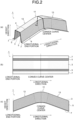
- a press-formed product 1 to be formed in the present invention has a hat-shaped cross section with a web portion 3, side wall portions 5 continuous from the web portion 3, and flange portions 7 continuous from the respective side wall portions 5, and includes a convex curved portion 11 in which the web portion 3 and the flange portions 7 are convexly curved in the height direction along the longitudinal direction in side view ( FIG. 2(c) ).
- Straight portions 13 extending in a straight shape are provided on both sides of the convex curved portion 11 in the longitudinal direction.
- the convex curved portion 11 being convexly curved in the height direction along the longitudinal direction means that the center of the convexly curved arc is located on the flange portion 7 side in side view.
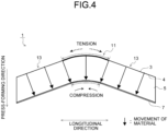
- FIG. 4 illustrates the movement of a material during press forming when the press-formed product 1 is viewed in side view.
- the blank In a process of press forming a blank (metal sheet), the blank is bent at a punch corner portion 4 between the web portion 3 and each of the side wall portions 5, and the material moves in a direction (direction of the arrows in FIG. 4 ) orthogonal to the ridgeline of the punch corner portion 4.
- the longitudinal length of the web portion 3 becomes longer while the longitudinal length of each of the flange portions 7 becomes shorter due to the concentration of the material, resulting in a line length difference in the longitudinal direction between the web portion 3 and the flange portion 7.
- tensile deformation acts on the web portion 3, causing it to fracture easily
- compressive deformation acts on the flange portion 7, causing it to wrinkle easily.
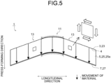
- FIG. 5 illustrates the movement of the material in the ideal state.
- a portion corresponding to the side wall portion 5 hereinafter referred to as a "portion corresponding to side wall”
- a die basically moves only in the vertical direction, and it is not easy to generate in-plane shear deformation in the material at the portion corresponding to side wall by this limited movement of the die.
- the inventors have studied a method to induce in-plane shear deformation in the material. As a result, it has been found that in-plane shear deformation can be generated in the portion corresponding to side wall of the blank by press-forming it into a curved surface shape with an out-of-plane twist along the longitudinal direction.
- the present invention has been made based on such studies, and the press forming method according to the embodiment of the present invention is described below.
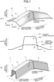
- the press forming method according to the present embodiment is to press-form the press-formed product 1 illustrated in FIG. 1(b) and FIG. 2 as a target shape, and includes a first forming process to preform a blank into a preformed part 21 ( FIGS. 1 (a-1) and 1(a-2)), and a second forming process to press-form the preformed part 21 into the press-formed product 1 having the target shape.
- the blank used for the press forming method according to the present invention is not limited to a steel sheet and may be a sheet made of a plastic material such as an aluminum alloy sheet, a magnesium alloy sheet, a titanium alloy sheet, and a plastic sheet, for example.
- the material strength of the blank is not specifically limited.
- the preformed part 21 has a hat-shaped cross section with a portion 23 corresponding to web corresponding to the web portion 3 of the press-formed product 1, portions 25 corresponding to side wall corresponding to the side wall portions 5 of the press-formed product 1 and including respective twisted side wall portions 25a of a curved surface shape twisted along the longitudinal direction compared with the side wall portion 5, and portions 27 corresponding to flange corresponding to the flange portions 7 of the press-formed product 1, and includes a portion 31 corresponding to convex curve corresponding to the convex curved portion 11 of the press-formed product 1, and portions 33 corresponding to straight portion corresponding to the straight portions 13.
- FIG. 1 (a-2) illustrates the shapes of the sections of the preformed part 21, the sections being orthogonal to the longitudinal direction of the preformed part 21, at the center of the portion 31 corresponding to convex curve in the longitudinal direction (hereinafter referred to as a "convex curve center”) and at an end portion of the twisted side wall portion 25a in the longitudinal direction (hereinafter referred to as a "longitudinal end portion").
- the shapes of the sections illustrated in FIG. 1 (a-2) are depicted with the positions of the portions 27 corresponding to flange in the height direction aligned with each other for convenience of explanation.
- Each of the twisted side wall portions 25a is twisted such that an angle ⁇ 2 at the longitudinal end portion is larger than an angle ⁇ 1 at the convex curve center where an angle between the twisted side wall portion 25a and the portion 23 corresponding to web is ⁇ , as illustrated in FIG. 1 (a-2). With this twisting, the angle ⁇ between the twisted side wall portion 25a and the portion 23 corresponding to web changes continuously along the longitudinal direction.
- the portion 23 corresponding to web of the preformed part 21 has the same shape as that of the web portion 3 ( FIG. 2 ) of the press-formed product 1, as illustrated in FIG. 1 .
- each of the portions 27 corresponding to flange of the preformed part 21 is continuous with the portion 25 corresponding to side wall including the twisted side wall portion 25a, which has a different shape from that of the side wall portion 5, as illustrated in FIG. 1 .
- the portion 27 corresponding to flange has a different shape in plan view and side view from that of the flange portion 7 of the press-formed product 1 ( FIGS. 2(b) and 2(c) ), as illustrated in FIGS. 6(b) and 6(c) .
- the angle between the portion 23 corresponding to web and the twisted side wall portion 25a of the preformed part 21 is larger at the longitudinal end portion ( ⁇ 2 ) than at the convex curve center ( ⁇ 1 ) (refer to FIG. 1 (a-2)).
- the formed height of the preformed part 21 in the height direction is not constant along the longitudinal direction and differs from the formed height of the press-formed product 1 in the height direction.
- the ridgeline length of a punch corner portion 24 ( FIG. 6 ) between the portion 23 corresponding to web and each of the portions 25 corresponding to side wall of the preformed part 21 is different from the ridgeline length of the punch corner portion 4 ( FIG. 2 ) of the press-formed product 1, or the ridgeline length of a die corner portion 26 ( FIG. 6 ) between the portion 25 corresponding to side wall and each of the portions 27 corresponding to flange is different from the ridgeline length of a die corner portion 6 ( FIG. 2 ) of the press-formed product 1.
- the ridgeline length of the punch corner portion 24 is the same as that of the press-formed product 1, but the ridgeline length of the die corner portion 26 is different from that of the press-formed product 1.
- the portion 27 corresponding to flange is formed into the same shape as that of the flange portion 7 of the press-formed product 1 having the target shape, the ridgeline length of the die corner portion 26 is the same as that of the press-formed product 1, but the ridgeline length of the punch corner portion 24 is different from that of the press-formed product 1.
- the second forming process is a process to press-form the preformed part 21 ( FIGS. 1 (a-1) and 1(a-2)) into the press-formed product 1 having the target shape ( FIG. 1(b) ).
- the portion 25 corresponding to side wall including the twisted side wall portion 25a having the angle between the twisted side wall portion 25a and the portion 23 corresponding to web changing along the longitudinal direction, is formed into the side wall portion 5 of the target shape.
- the portion 27 corresponding to flange is formed into the flange portion 7 of the target shape.
- the press forming method according to the present embodiment can press-form a press-formed product that is convexly curved in the height direction along the longitudinal direction in side view, while suppressing fractures and wrinkles.
- each of the twisted side wall portions 25a with a curved surface shape with an out-of-plane twist along the longitudinal direction are formed on the portion 25 corresponding to side wall corresponding to the side wall portion 5 of the press-formed product 1.
- the material blade
- the material undergoes in-plane shear deformation in addition to out-of-plane shear deformation, as illustrated in FIG. 7 .
- This configuration suppresses the movement of the material toward the center of the portion 27 corresponding to flange in the longitudinal direction in the portion 31 corresponding to convex curve, and also suppresses the movement of the material toward the end portion side in the longitudinal direction in the portion 23 corresponding to web.
- the line length difference between the line length of the portion 23 corresponding to web in the longitudinal direction and the line length of the portion 27 corresponding to flange in the longitudinal direction is reduced, as illustrated in FIG. 5 .
- fractures in the web portion 3 and wrinkles in the flange portion 7 are suppressed in the press-formed product 1, which is obtained by press-forming the preformed part 21 into the target shape at the second forming process.
- the press forming method according to the present invention suppresses fractures in the web portion 3 and wrinkles in the flange portion 7 of the press-formed product 1 ( FIG. 2 ) having the target shape, by causing in-plane shear deformation in the twisted side wall portion 25a at the first forming process.
- the magnitude of in-plane shear deformation in the twisted side wall portion 25a depends on the degree of torsion of the twisted side wall portion 25a.
- the degree of torsion of the twisted side wall portion 25a can be expressed using an angle change and an aspect ratio of the twisted side wall portion 25a.
- the angle change of the twisted side wall portion 25a is given by the angle difference ⁇ between the angle ⁇ 1 at the convex curve center (the center of the portion 31 corresponding to convex curve in the longitudinal direction) and the angle ⁇ 2 at the longitudinal end portion (the end portion of the twisted side wall portion 25a in the longitudinal direction), which are the angles between the twisted side wall portion 25a and the portion 23 corresponding to web (refer to FIG. 1 (a-2)).
- the aspect ratio of the twisted side wall portion 25a is given by a ratio H/L, which is the ratio of a side wall height H to a longitudinal length L of the twisted side wall portion 25a, as illustrated in FIG. 8 .
- the side wall height H and the longitudinal length L of the twisted side wall portion are the height in the direction orthogonal to the longitudinal direction and the length in the longitudinal direction, both in the plane of the twisted side wall portion 25a.
- the torsion amount T can be changed by changing (1) the angle ⁇ 1 between the twisted side wall portion 25a and the portion 23 corresponding to web at the convex curve center, (2) the angle ⁇ 2 between the twisted side wall portion 25a and the portion 23 corresponding to web at the longitudinal end portion, (3) the side wall height H of the twisted side wall portion 25a, and (4) the longitudinal length L of the twisted side wall portion 25a.
- FIG. 9 illustrates an example of a preformed part 41 in which the height H of the twisted side wall portion 25a is changed
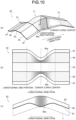
- FIG. 10 illustrates an example of a preformed part 61 in which the longitudinal length L of the twisted side wall portion 25a is changed.
- the preformed part 21 illustrated in FIGS. 1 and 6 described above includes the twisted side wall portion 25a formed over the entire length of the preformed part 21 in the longitudinal direction.
- the preformed part 61 illustrated in FIG. 10 includes twisted side wall portions 65a each having a longitudinal length L shorter than the longitudinal length of the side wall portion 5 of the press-formed product 1.
- the angle ⁇ 2 between the twisted side wall portion 65a and a portion 63 corresponding to web at an end portion in the longitudinal direction is not an angle at an end portion of the entire preformed part 61 in the longitudinal direction, but an angle at an end portion of only the twisted side wall portion 65a in the longitudinal direction.
- the angle ⁇ 2 at the longitudinal end portion needs to be larger than the angle ⁇ 1 at the convex curve center, as described above. For example, if the angle ⁇ 2 at the longitudinal end portion is smaller than the angle ⁇ 1 at the convex curve center as illustrated in FIG. 11 , the in-plane shear deformation in the twisted side wall portion 85a will be in the opposite direction to that in the twisted side wall portion 25a illustrated in FIG. 7 , as illustrated in FIG. 12 .
- the torsion amount T suitable for suppressing fractures and wrinkles was investigated by finite element method (FEM) simulation. As a result, it was found that setting the torsion amount T to be in the range of 10° or larger and 20° or smaller is desirable to suppress both fractures and wrinkles.
- FEM finite element method
- the aspect ratio H/L of the twisted side wall portion 25a may be given by using the side wall height H at the center of the longitudinal length (a middle position between the convex curve center and the longitudinal end portion) and the longitudinal length L at the center in the side wall height direction, of the twisted side wall portion 25a.
- the preformed part 21 ( FIGS. 1 and 6 ), the preformed part 41 ( FIG. 9 ), and the preformed part 61 ( FIG. 10 ) each have the portion corresponding to web having the same shape as that of the web portion of the target shape, and have the portions corresponding to flange having a different shape from that of the flange portions 7 of the target shape.
- the present invention may form portions 107 corresponding to flange having the same shape as that of the flange portions 7 of the target shape ( FIG. 2 ), and may form a portion 103 corresponding to web having a different shape from that of the web portion 3 of the target shape, as in a preformed part 101 illustrated in FIG. 13 .
- the press-formed product 1 to be formed as described above includes the web portion 3 and the flange portion 7 both being convexly curved in the height direction along the longitudinal direction.
- the present invention may be used to form a press-formed product 121 in which a web portion 123 alone is convexly curved or a press-formed product 141 in which a flange portion 147 alone is convexly curved.
- the above explanation is for forming a press-formed product such as the press-formed product 1 illustrated in FIG. 2 in which the radius of curvature of the convex curved portion 11 is constant in the longitudinal direction.
- the present invention may be used to form a press-formed product that has a plurality of consecutive convex curved portions with different radii of curvature.
- the twisted side wall portion in the convex curved portion may have a curved surface shape twisted from the center toward the end portion of the convex curved portion in the longitudinal direction. Then, for each convex curved portion, the angle between the portion corresponding to web and the twisted side wall portion at the longitudinal end portion of the twisted side wall portion of the convex curved portion may be larger than that at the center of the convex curved portion in the longitudinal direction.
- the press-formed product 1 to be formed in the present embodiment includes the straight portions 13 on both sides of the convex curved portion 11 in the longitudinal direction.
- the present invention may be used to form a press-formed product including a straight portion on one side of the convex curved portion in the longitudinal direction or a press-formed product including the convex curved portion alone.
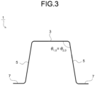
- the angle between the web portion 3 and the side wall portion 5 is constant along the longitudinal direction, that is, as illustrated in FIG. 3 , the angle ⁇ 1,0 at the convex curve center of the press-formed product 1 (the center of the convex curved portion 11 in the longitudinal direction) and the angle ⁇ 2,0 at the longitudinal end portion (the end portion of the side wall portion 5 in the longitudinal direction) are equal.
- the present invention may be used to form a press-formed product in which the angle between the web portion and the side wall portion changes along the longitudinal direction, that is, the side wall portion has a curved surface shape twisted along the longitudinal direction.
- the angle difference between the angle at the end portion of the twisted side wall portion in the longitudinal direction and the angle at the center of the portion corresponding to convex curve in the longitudinal direction in the preformed part may be made larger than the angle difference between the angle at the center of the convex curved portion in the longitudinal direction (convex curve center) and the angle at the end portion of the side wall portion in the longitudinal direction (longitudinal end portion) in the press-formed product of the target shape, so that the twisted side wall portion of the preformed part may have a curved surface shape more twisted along the longitudinal direction than that of the side wall portion of the target shape.
- the angle between the portion corresponding to web and the twisted side wall portion at the convex curve center of the preformed part may be the angle between the web portion and the side wall portion at the convex curve center of the target shape, and the angle between the portion corresponding to web and the twisted side wall portion at the longitudinal end portion of the preformed part may be larger than the angle between the web portion and the side wall portion at the longitudinal end of the target shape.
- the portion 27 corresponding to flange may undergo compressive deformation and wrinkles may occur.
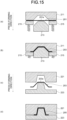
- drawing forming is desirable for the first forming process, in which the blank 201 is press-formed with its end portions being clamped with blank holders 215 and a die 211 as illustrated in FIGS. 15(a) and 15(b) .
- the preformed part 203 is bent at each punch corner portion 24 between the portion 23 corresponding to web and the portion 25 corresponding to side wall, and the twisted side wall portion of the preformed part 203 is formed into the side wall portion of the target shape.
- crash forming may be employed for the second forming process, in which the preformed part 203 is press-formed by being sandwiched between a die 221 and a punch 223 as illustrated in FIGS. 15(c) and 15(d) .
- drawing forming may be used at the second forming process.
- a pad (not illustrated) that is paired with a punch 213 ( FIGS. 15(a) and 15(b) ) or the punch 223 ( FIGS. 15(c) and 15(d) ) may be inserted on the die 211 side ( FIGS. 15(a) and 15(b) ) or the die 221 side ( FIGS. 15(c) and 15(d) ), and a part 201a (refer to FIG. 15(a) ) in the blank 201 corresponding to a portion 203a corresponding to web of the preformed part 203 at the first forming process, or the portion 203a corresponding to web (refer to FIG. 15(c) ) of the preformed part 203 at the second forming process, may be pressed down with the pad while being forming.
- a press forming method can be provided that can press-form, into a favorable shape, a press-formed product having a hat-shaped cross section with a web portion, a side wall portion, and a flange portion, the press-formed product being convexly curved in the height direction along the longitudinal direction, while suppressing fractures and wrinkles.
Landscapes
- Engineering & Computer Science (AREA)
- Mechanical Engineering (AREA)
- Shaping Metal By Deep-Drawing, Or The Like (AREA)
- Bending Of Plates, Rods, And Pipes (AREA)
Claims (1)
- Ein Pressformverfahren zum Formen eines pressgeformten Produkts (1) mit einem hutförmigen Querschnitt, das Folgendes umfasst: einen Stegabschnitt (3); einen Seitenwandabschnitt (5), der sich an den Stegabschnitt (3) anschließt; einen Flanschabschnitt (7), der sich an den Seitenwandabschnitt (5) fortsetzt; und einen konvex gekrümmten Abschnitt (11), in dem der Stegabschnitt (3) und/oder der Flanschabschnitt (7) in einer Höhenrichtung entlang einer Längsrichtung in einer Seitenansicht konvex gekrümmt ist, wobei das Pressformverfahren umfasst:einen ersten Umformprozess des Pressformens eines vorgeformten Teils (21), bei dem ein Abschnitt, der dem Stegabschnitt (23) entspricht, und ein Abschnitt, der dem Seitenwandabschnitt (25) entspricht und einen verdrehten Seitenwandabschnitt (25a) mit einer verdrehten Form entlang der Längsrichtung umfasst, geformt werden, wobei das vorgeformte Teil (21) einen Abschnitt umfasst, der dem konvex gekrümmten Abschnitt (31) entspricht; undein zweiter Formungsprozess des Pressformens des vorgeformten Teils (21) in das pressgeformte Produkt (1),wobei der verdrehte Seitenwandabschnitt (25) beim ersten Formungsprozess so verdreht wird, dass ein Winkel zwischen dem verdrehten Seitenwandabschnitt (25) und dem Abschnitt, der dem Stegabschnitt (23) entspricht, an einer Endabschnittseite größer ist als in einer Mitte des Abschnitts, der dem konvex gekrümmten Abschnitt (31) in der Längsrichtung entspricht,wobei das Pressformverfahren dadurch gekennzeichnet ist, dass der verdrehte Seitenwandabschnitt (25a) beim ersten Formungsprozess einen Torsionsbetrag T aufweist, der durch die folgende Gleichung gegeben ist, wobei der Torsionsbetrag T so eingestellt wird, dass er in einem Bereich von 10° oder mehr und 20° oder weniger liegt:
 Δθ eine Winkeldifferenz (= θ2 - θ1),θ1: ein Winkel (°) zwischen dem verdrehten Seitenwandabschnitt (25a) und dem Abschnitt, der dem Stegabschnitt (23) in der Mitte des Abschnitts entspricht, der dem konvex gekrümmten Abschnitt (31) in Längsrichtung entspricht,θ2: ein Winkel (°) zwischen dem verdrehten Seitenwandabschnitt (25a) und dem Abschnitt, der dem Stegabschnitt (23) an einem Endabschnitt des verdrehten Seitenwandabschnitts (25a) in Längsrichtung entspricht,H: eine Seitenwandhöhe (mm) des verdrehten Seitenwandabschnitts (25a) ist, undL: eine Längslänge (mm) des verdrehten Seitenwandabschnitts (25a) entspricht.
Applications Claiming Priority (2)
| Application Number | Priority Date | Filing Date | Title |
|---|---|---|---|
| JP2019080657A JP6733772B1 (ja) | 2019-04-22 | 2019-04-22 | プレス成形方法 |
| PCT/JP2019/051362 WO2020217593A1 (ja) | 2019-04-22 | 2019-12-27 | プレス成形方法 |
Publications (3)
| Publication Number | Publication Date |
|---|---|
| EP3960321A1 EP3960321A1 (de) | 2022-03-02 |
| EP3960321A4 EP3960321A4 (de) | 2022-05-11 |
| EP3960321B1 true EP3960321B1 (de) | 2025-03-12 |
Family
ID=71892474
Family Applications (1)
| Application Number | Title | Priority Date | Filing Date |
|---|---|---|---|
| EP19926276.7A Active EP3960321B1 (de) | 2019-04-22 | 2019-12-27 | Pressformverfahren |
Country Status (7)
| Country | Link |
|---|---|
| US (1) | US12109600B2 (de) |
| EP (1) | EP3960321B1 (de) |
| JP (1) | JP6733772B1 (de) |
| KR (1) | KR102545162B1 (de) |
| CN (1) | CN113727791B (de) |
| MX (1) | MX2021012786A (de) |
| WO (1) | WO2020217593A1 (de) |
Families Citing this family (4)
| Publication number | Priority date | Publication date | Assignee | Title |
|---|---|---|---|---|
| JP6696611B1 (ja) * | 2019-05-13 | 2020-05-20 | Jfeスチール株式会社 | プレス成形方法 |
| JP7239048B1 (ja) * | 2022-02-10 | 2023-03-14 | Jfeスチール株式会社 | プレス成形方法及びプレス成形品の製造方法 |
| CN116078923B (zh) * | 2023-01-28 | 2025-11-18 | 安徽江淮汽车集团股份有限公司 | 冲压拉延成形工艺及汽车悬架支撑板冲压工艺 |
| CN117020050B (zh) * | 2023-08-11 | 2025-11-18 | 东风柳州汽车有限公司 | 一种汽车连接板的成型工艺方法及汽车连接板 |
Family Cites Families (20)
| Publication number | Priority date | Publication date | Assignee | Title |
|---|---|---|---|---|
| JPS51119537A (en) | 1975-04-11 | 1976-10-20 | Matsushita Electric Ind Co Ltd | Water controller |
| JPS6215903Y2 (de) | 1980-08-06 | 1987-04-22 | ||
| JP5217928B2 (ja) | 2008-11-12 | 2013-06-19 | 新日鐵住金株式会社 | プレス加工方法及びプレス成形体 |
| JP2011206789A (ja) * | 2010-03-29 | 2011-10-20 | Kobe Steel Ltd | プレス成形方法 |
| KR101472645B1 (ko) | 2010-05-19 | 2014-12-15 | 신닛테츠스미킨 카부시키카이샤 | L자 형상을 갖는 부품의 프레스 성형 방법 |
| JP5965159B2 (ja) | 2012-02-22 | 2016-08-03 | 東プレ株式会社 | プレス部品の成形方法 |
| CA2882244C (en) | 2012-09-12 | 2017-06-06 | Nippon Steel & Sumitomo Metal Corporation | Method for producing curved part, and skeleton structure member of body shell of automobile |
| BR112015016037A2 (pt) | 2013-01-16 | 2017-07-11 | Nippon Steel & Sumitomo Metal Corp | método de formação por prensagem |
| BR112017006100A2 (pt) | 2014-10-01 | 2017-12-19 | Nippon Steel & Sumitomo Metal Corp | método de produção, equipamento de produção, e linha do equipamento de produção de produto conformado por prensagem |
| US10213819B2 (en) * | 2015-02-27 | 2019-02-26 | Sango Co., Ltd. | Press forming method |
| JP6361902B2 (ja) * | 2015-07-13 | 2018-07-25 | Jfeスチール株式会社 | プレス成形方法およびプレス成形部品の製造方法 |
| JP6380294B2 (ja) * | 2015-08-24 | 2018-08-29 | Jfeスチール株式会社 | プレス成形方法 |
| DE102015118099A1 (de) * | 2015-10-23 | 2017-04-27 | Benteler Automobiltechnik Gmbh | Verfahren zur Herstellung eines Kraftfahrzeugbauteils |
| RU2693402C1 (ru) * | 2016-03-28 | 2019-07-02 | Ниппон Стил Энд Сумитомо Метал Корпорейшн | Способ изготовления штампованного изделия |
| JP6512191B2 (ja) * | 2016-08-03 | 2019-05-15 | Jfeスチール株式会社 | 金型の設計方法およびプレス成形品の製造方法 |
| WO2018066663A1 (ja) * | 2016-10-05 | 2018-04-12 | 新日鐵住金株式会社 | プレス成形品の製造方法および製造装置 |
| JP6330930B1 (ja) * | 2017-01-27 | 2018-05-30 | Jfeスチール株式会社 | プレス成形方法 |
| JP6515961B2 (ja) * | 2017-08-02 | 2019-05-22 | Jfeスチール株式会社 | プレス成形品の製造方法 |
| MX2020008953A (es) * | 2018-02-28 | 2020-10-15 | Jfe Steel Corp | Metodo de produccion para componentes prensados, dispositivo de moldeado por prensado, y lamina de metal para moldeado por prensado. |
| MX2020014023A (es) | 2018-07-03 | 2021-03-09 | Jfe Steel Corp | Metodo para el dise?o de forma de molde y metodo para la produccion de parte prensada. |
-
2019
- 2019-04-22 JP JP2019080657A patent/JP6733772B1/ja active Active
- 2019-12-27 WO PCT/JP2019/051362 patent/WO2020217593A1/ja not_active Ceased
- 2019-12-27 EP EP19926276.7A patent/EP3960321B1/de active Active
- 2019-12-27 KR KR1020217034059A patent/KR102545162B1/ko active Active
- 2019-12-27 US US17/602,093 patent/US12109600B2/en active Active
- 2019-12-27 MX MX2021012786A patent/MX2021012786A/es unknown
- 2019-12-27 CN CN201980095587.XA patent/CN113727791B/zh active Active
Also Published As
| Publication number | Publication date |
|---|---|
| WO2020217593A1 (ja) | 2020-10-29 |
| KR20210141654A (ko) | 2021-11-23 |
| US12109600B2 (en) | 2024-10-08 |
| JP2020175426A (ja) | 2020-10-29 |
| US20220143672A1 (en) | 2022-05-12 |
| JP6733772B1 (ja) | 2020-08-05 |
| KR102545162B1 (ko) | 2023-06-16 |
| EP3960321A4 (de) | 2022-05-11 |
| MX2021012786A (es) | 2021-12-10 |
| EP3960321A1 (de) | 2022-03-02 |
| CN113727791A (zh) | 2021-11-30 |
| CN113727791B (zh) | 2024-03-22 |
Similar Documents
| Publication | Publication Date | Title |
|---|---|---|
| EP2896467B1 (de) | Verfahren zur herstellung gekrümmter artikel | |
| EP3960321A1 (de) | Pressformverfahren | |
| CN112154036B (zh) | 冲压部件的制造方法 | |
| CN106660098B (zh) | 冲压成形方法 | |
| US11517954B2 (en) | Pressed component manufacturing method and press apparatus | |
| EP3960322B1 (de) | Pressformverfahren | |
| EP3320996A1 (de) | Verfahren und vorrichtung zur herstellung einer pressenkomponente | |
| EP3895824B1 (de) | Formpressverfahren | |
| CN107921504B (zh) | 拉伸凸缘成形零件的制造方法 | |
| EP3915694B1 (de) | Pressformverfahren und pressmaschine | |
| EP4321269A1 (de) | Pressformverfahren | |
| KR20260042224A (ko) | 프레스 성형품의 제조 방법 | |
| EP4454777A1 (de) | Pressformverfahren und herstellungsverfahren für pressformartikel | |
| JP2022072562A (ja) | プレス成形方法、プレス成形用金型およびプレス成形用金型の設計方法 | |
| KR102862573B1 (ko) | 프레스 성형 방법 |
Legal Events
| Date | Code | Title | Description |
|---|---|---|---|
| STAA | Information on the status of an ep patent application or granted ep patent |
Free format text: STATUS: THE INTERNATIONAL PUBLICATION HAS BEEN MADE |
|
| PUAI | Public reference made under article 153(3) epc to a published international application that has entered the european phase |
Free format text: ORIGINAL CODE: 0009012 |
|
| STAA | Information on the status of an ep patent application or granted ep patent |
Free format text: STATUS: REQUEST FOR EXAMINATION WAS MADE |
|
| 17P | Request for examination filed |
Effective date: 20211011 |
|
| AK | Designated contracting states |
Kind code of ref document: A1 Designated state(s): AL AT BE BG CH CY CZ DE DK EE ES FI FR GB GR HR HU IE IS IT LI LT LU LV MC MK MT NL NO PL PT RO RS SE SI SK SM TR |
|
| REG | Reference to a national code |
Ref country code: DE Ref legal event code: R079 Free format text: PREVIOUS MAIN CLASS: B21D0022260000 Ipc: B21D0022200000 Ref country code: DE Ref legal event code: R079 Ref document number: 602019067344 Country of ref document: DE Free format text: PREVIOUS MAIN CLASS: B21D0022260000 Ipc: B21D0022200000 |
|
| A4 | Supplementary search report drawn up and despatched |
Effective date: 20220413 |
|
| RIC1 | Information provided on ipc code assigned before grant |
Ipc: B21D 22/22 20060101ALI20220407BHEP Ipc: B21D 22/02 20060101ALI20220407BHEP Ipc: B21D 53/88 20060101ALI20220407BHEP Ipc: B21D 22/20 20060101AFI20220407BHEP |
|
| DAV | Request for validation of the european patent (deleted) | ||
| DAX | Request for extension of the european patent (deleted) | ||
| GRAP | Despatch of communication of intention to grant a patent |
Free format text: ORIGINAL CODE: EPIDOSNIGR1 |
|
| STAA | Information on the status of an ep patent application or granted ep patent |
Free format text: STATUS: GRANT OF PATENT IS INTENDED |
|
| INTG | Intention to grant announced |
Effective date: 20241205 |
|
| GRAS | Grant fee paid |
Free format text: ORIGINAL CODE: EPIDOSNIGR3 |
|
| GRAA | (expected) grant |
Free format text: ORIGINAL CODE: 0009210 |
|
| STAA | Information on the status of an ep patent application or granted ep patent |
Free format text: STATUS: THE PATENT HAS BEEN GRANTED |
|
| AK | Designated contracting states |
Kind code of ref document: B1 Designated state(s): AL AT BE BG CH CY CZ DE DK EE ES FI FR GB GR HR HU IE IS IT LI LT LU LV MC MK MT NL NO PL PT RO RS SE SI SK SM TR |
|
| REG | Reference to a national code |
Ref country code: GB Ref legal event code: FG4D |
|
| REG | Reference to a national code |
Ref country code: CH Ref legal event code: EP |
|
| REG | Reference to a national code |
Ref country code: DE Ref legal event code: R096 Ref document number: 602019067344 Country of ref document: DE |
|
| REG | Reference to a national code |
Ref country code: IE Ref legal event code: FG4D |
|
| PG25 | Lapsed in a contracting state [announced via postgrant information from national office to epo] |
Ref country code: RS Free format text: LAPSE BECAUSE OF FAILURE TO SUBMIT A TRANSLATION OF THE DESCRIPTION OR TO PAY THE FEE WITHIN THE PRESCRIBED TIME-LIMIT Effective date: 20250612 |
|
| PG25 | Lapsed in a contracting state [announced via postgrant information from national office to epo] |
Ref country code: FI Free format text: LAPSE BECAUSE OF FAILURE TO SUBMIT A TRANSLATION OF THE DESCRIPTION OR TO PAY THE FEE WITHIN THE PRESCRIBED TIME-LIMIT Effective date: 20250312 |
|
| PG25 | Lapsed in a contracting state [announced via postgrant information from national office to epo] |
Ref country code: ES Free format text: LAPSE BECAUSE OF FAILURE TO SUBMIT A TRANSLATION OF THE DESCRIPTION OR TO PAY THE FEE WITHIN THE PRESCRIBED TIME-LIMIT Effective date: 20250312 |
|
| REG | Reference to a national code |
Ref country code: LT Ref legal event code: MG9D |
|
| PG25 | Lapsed in a contracting state [announced via postgrant information from national office to epo] |
Ref country code: NO Free format text: LAPSE BECAUSE OF FAILURE TO SUBMIT A TRANSLATION OF THE DESCRIPTION OR TO PAY THE FEE WITHIN THE PRESCRIBED TIME-LIMIT Effective date: 20250612 |
|
| PG25 | Lapsed in a contracting state [announced via postgrant information from national office to epo] |
Ref country code: HR Free format text: LAPSE BECAUSE OF FAILURE TO SUBMIT A TRANSLATION OF THE DESCRIPTION OR TO PAY THE FEE WITHIN THE PRESCRIBED TIME-LIMIT Effective date: 20250312 |
|
| REG | Reference to a national code |
Ref country code: NL Ref legal event code: MP Effective date: 20250312 |
|
| PG25 | Lapsed in a contracting state [announced via postgrant information from national office to epo] |
Ref country code: LV Free format text: LAPSE BECAUSE OF FAILURE TO SUBMIT A TRANSLATION OF THE DESCRIPTION OR TO PAY THE FEE WITHIN THE PRESCRIBED TIME-LIMIT Effective date: 20250312 |
|
| PG25 | Lapsed in a contracting state [announced via postgrant information from national office to epo] |
Ref country code: GR Free format text: LAPSE BECAUSE OF FAILURE TO SUBMIT A TRANSLATION OF THE DESCRIPTION OR TO PAY THE FEE WITHIN THE PRESCRIBED TIME-LIMIT Effective date: 20250613 Ref country code: BG Free format text: LAPSE BECAUSE OF FAILURE TO SUBMIT A TRANSLATION OF THE DESCRIPTION OR TO PAY THE FEE WITHIN THE PRESCRIBED TIME-LIMIT Effective date: 20250312 |
|
| REG | Reference to a national code |
Ref country code: AT Ref legal event code: MK05 Ref document number: 1774596 Country of ref document: AT Kind code of ref document: T Effective date: 20250312 |
|
| PG25 | Lapsed in a contracting state [announced via postgrant information from national office to epo] |
Ref country code: NL Free format text: LAPSE BECAUSE OF FAILURE TO SUBMIT A TRANSLATION OF THE DESCRIPTION OR TO PAY THE FEE WITHIN THE PRESCRIBED TIME-LIMIT Effective date: 20250312 |
|
| PG25 | Lapsed in a contracting state [announced via postgrant information from national office to epo] |
Ref country code: SE Free format text: LAPSE BECAUSE OF FAILURE TO SUBMIT A TRANSLATION OF THE DESCRIPTION OR TO PAY THE FEE WITHIN THE PRESCRIBED TIME-LIMIT Effective date: 20250312 |
|
| PG25 | Lapsed in a contracting state [announced via postgrant information from national office to epo] |
Ref country code: SM Free format text: LAPSE BECAUSE OF FAILURE TO SUBMIT A TRANSLATION OF THE DESCRIPTION OR TO PAY THE FEE WITHIN THE PRESCRIBED TIME-LIMIT Effective date: 20250312 |
|
| PG25 | Lapsed in a contracting state [announced via postgrant information from national office to epo] |
Ref country code: PT Free format text: LAPSE BECAUSE OF FAILURE TO SUBMIT A TRANSLATION OF THE DESCRIPTION OR TO PAY THE FEE WITHIN THE PRESCRIBED TIME-LIMIT Effective date: 20250714 |
|
| PG25 | Lapsed in a contracting state [announced via postgrant information from national office to epo] |
Ref country code: PL Free format text: LAPSE BECAUSE OF FAILURE TO SUBMIT A TRANSLATION OF THE DESCRIPTION OR TO PAY THE FEE WITHIN THE PRESCRIBED TIME-LIMIT Effective date: 20250312 Ref country code: IT Free format text: LAPSE BECAUSE OF FAILURE TO SUBMIT A TRANSLATION OF THE DESCRIPTION OR TO PAY THE FEE WITHIN THE PRESCRIBED TIME-LIMIT Effective date: 20250312 |
|
| PG25 | Lapsed in a contracting state [announced via postgrant information from national office to epo] |
Ref country code: AT Free format text: LAPSE BECAUSE OF FAILURE TO SUBMIT A TRANSLATION OF THE DESCRIPTION OR TO PAY THE FEE WITHIN THE PRESCRIBED TIME-LIMIT Effective date: 20250312 |
|
| PG25 | Lapsed in a contracting state [announced via postgrant information from national office to epo] |
Ref country code: EE Free format text: LAPSE BECAUSE OF FAILURE TO SUBMIT A TRANSLATION OF THE DESCRIPTION OR TO PAY THE FEE WITHIN THE PRESCRIBED TIME-LIMIT Effective date: 20250312 Ref country code: CZ Free format text: LAPSE BECAUSE OF FAILURE TO SUBMIT A TRANSLATION OF THE DESCRIPTION OR TO PAY THE FEE WITHIN THE PRESCRIBED TIME-LIMIT Effective date: 20250312 |
|
| PG25 | Lapsed in a contracting state [announced via postgrant information from national office to epo] |
Ref country code: RO Free format text: LAPSE BECAUSE OF FAILURE TO SUBMIT A TRANSLATION OF THE DESCRIPTION OR TO PAY THE FEE WITHIN THE PRESCRIBED TIME-LIMIT Effective date: 20250312 |
|
| PG25 | Lapsed in a contracting state [announced via postgrant information from national office to epo] |
Ref country code: SK Free format text: LAPSE BECAUSE OF FAILURE TO SUBMIT A TRANSLATION OF THE DESCRIPTION OR TO PAY THE FEE WITHIN THE PRESCRIBED TIME-LIMIT Effective date: 20250312 |
|
| PG25 | Lapsed in a contracting state [announced via postgrant information from national office to epo] |
Ref country code: IS Free format text: LAPSE BECAUSE OF FAILURE TO SUBMIT A TRANSLATION OF THE DESCRIPTION OR TO PAY THE FEE WITHIN THE PRESCRIBED TIME-LIMIT Effective date: 20250712 |
|
| REG | Reference to a national code |
Ref country code: DE Ref legal event code: R097 Ref document number: 602019067344 Country of ref document: DE |
|
| PGFP | Annual fee paid to national office [announced via postgrant information from national office to epo] |
Ref country code: DE Payment date: 20251104 Year of fee payment: 7 |
|
| PG25 | Lapsed in a contracting state [announced via postgrant information from national office to epo] |
Ref country code: DK Free format text: LAPSE BECAUSE OF FAILURE TO SUBMIT A TRANSLATION OF THE DESCRIPTION OR TO PAY THE FEE WITHIN THE PRESCRIBED TIME-LIMIT Effective date: 20250312 |
|
| PGFP | Annual fee paid to national office [announced via postgrant information from national office to epo] |
Ref country code: FR Payment date: 20251110 Year of fee payment: 7 |
|
| PLBE | No opposition filed within time limit |
Free format text: ORIGINAL CODE: 0009261 |
|
| STAA | Information on the status of an ep patent application or granted ep patent |
Free format text: STATUS: NO OPPOSITION FILED WITHIN TIME LIMIT |
|
| REG | Reference to a national code |
Ref country code: CH Ref legal event code: L10 Free format text: ST27 STATUS EVENT CODE: U-0-0-L10-L00 (AS PROVIDED BY THE NATIONAL OFFICE) Effective date: 20260121 |
|
| 26N | No opposition filed |
Effective date: 20251215 |