EP3960324A1 - Rotationsprägestempel - Google Patents
Rotationsprägestempel Download PDFInfo
- Publication number
- EP3960324A1 EP3960324A1 EP19806081.6A EP19806081A EP3960324A1 EP 3960324 A1 EP3960324 A1 EP 3960324A1 EP 19806081 A EP19806081 A EP 19806081A EP 3960324 A1 EP3960324 A1 EP 3960324A1
- Authority
- EP
- European Patent Office
- Prior art keywords
- rotating
- die
- slide surface
- fixed
- axis
- Prior art date
- Legal status (The legal status is an assumption and is not a legal conclusion. Google has not performed a legal analysis and makes no representation as to the accuracy of the status listed.)
- Pending
Links
Images



Classifications
-
- B—PERFORMING OPERATIONS; TRANSPORTING
- B21—MECHANICAL METAL-WORKING WITHOUT ESSENTIALLY REMOVING MATERIAL; PUNCHING METAL
- B21D—WORKING OR PROCESSING OF SHEET METAL OR METAL TUBES, RODS OR PROFILES WITHOUT ESSENTIALLY REMOVING MATERIAL; PUNCHING METAL
- B21D19/00—Flanging or other edge treatment, e.g. of tubes
- B21D19/08—Flanging or other edge treatment, e.g. of tubes by single or successive action of pressing tools, e.g. vice jaws
- B21D19/082—Flanging or other edge treatment, e.g. of tubes by single or successive action of pressing tools, e.g. vice jaws for making negative angles
- B21D19/086—Flanging or other edge treatment, e.g. of tubes by single or successive action of pressing tools, e.g. vice jaws for making negative angles with rotary cams
-
- B—PERFORMING OPERATIONS; TRANSPORTING
- B21—MECHANICAL METAL-WORKING WITHOUT ESSENTIALLY REMOVING MATERIAL; PUNCHING METAL
- B21D—WORKING OR PROCESSING OF SHEET METAL OR METAL TUBES, RODS OR PROFILES WITHOUT ESSENTIALLY REMOVING MATERIAL; PUNCHING METAL
- B21D28/00—Shaping by press-cutting; Perforating
- B21D28/24—Perforating, i.e. punching holes
- B21D28/32—Perforating, i.e. punching holes in other articles of special shape
-
- B—PERFORMING OPERATIONS; TRANSPORTING
- B21—MECHANICAL METAL-WORKING WITHOUT ESSENTIALLY REMOVING MATERIAL; PUNCHING METAL
- B21D—WORKING OR PROCESSING OF SHEET METAL OR METAL TUBES, RODS OR PROFILES WITHOUT ESSENTIALLY REMOVING MATERIAL; PUNCHING METAL
- B21D37/00—Tools as parts of machines covered by this subclass
- B21D37/01—Selection of materials
-
- B—PERFORMING OPERATIONS; TRANSPORTING
- B21—MECHANICAL METAL-WORKING WITHOUT ESSENTIALLY REMOVING MATERIAL; PUNCHING METAL
- B21D—WORKING OR PROCESSING OF SHEET METAL OR METAL TUBES, RODS OR PROFILES WITHOUT ESSENTIALLY REMOVING MATERIAL; PUNCHING METAL
- B21D37/00—Tools as parts of machines covered by this subclass
- B21D37/08—Dies with different parts for several steps in a process
-
- B—PERFORMING OPERATIONS; TRANSPORTING
- B21—MECHANICAL METAL-WORKING WITHOUT ESSENTIALLY REMOVING MATERIAL; PUNCHING METAL
- B21D—WORKING OR PROCESSING OF SHEET METAL OR METAL TUBES, RODS OR PROFILES WITHOUT ESSENTIALLY REMOVING MATERIAL; PUNCHING METAL
- B21D37/00—Tools as parts of machines covered by this subclass
- B21D37/10—Die sets; Pillar guides
-
- B—PERFORMING OPERATIONS; TRANSPORTING
- B21—MECHANICAL METAL-WORKING WITHOUT ESSENTIALLY REMOVING MATERIAL; PUNCHING METAL
- B21D—WORKING OR PROCESSING OF SHEET METAL OR METAL TUBES, RODS OR PROFILES WITHOUT ESSENTIALLY REMOVING MATERIAL; PUNCHING METAL
- B21D37/00—Tools as parts of machines covered by this subclass
- B21D37/10—Die sets; Pillar guides
- B21D37/12—Particular guiding equipment, e.g. pliers; Special arrangements for interconnection or cooperation of dies
-
- B—PERFORMING OPERATIONS; TRANSPORTING
- B21—MECHANICAL METAL-WORKING WITHOUT ESSENTIALLY REMOVING MATERIAL; PUNCHING METAL
- B21D—WORKING OR PROCESSING OF SHEET METAL OR METAL TUBES, RODS OR PROFILES WITHOUT ESSENTIALLY REMOVING MATERIAL; PUNCHING METAL
- B21D5/00—Bending sheet metal along straight lines, e.g. to form simple curves
- B21D5/01—Bending sheet metal along straight lines, e.g. to form simple curves between rams and anvils or abutments
-
- B—PERFORMING OPERATIONS; TRANSPORTING
- B21—MECHANICAL METAL-WORKING WITHOUT ESSENTIALLY REMOVING MATERIAL; PUNCHING METAL
- B21D—WORKING OR PROCESSING OF SHEET METAL OR METAL TUBES, RODS OR PROFILES WITHOUT ESSENTIALLY REMOVING MATERIAL; PUNCHING METAL
- B21D53/00—Making other particular articles
- B21D53/88—Making other particular articles other parts for vehicles, e.g. cowlings, mudguards
Definitions
- the present invention relates to a rotary press die which rotates a cam and presses a panel-shaped work to form a negative angle part.
- a rotary press die including a cylindrical rotary cam having the shape of a cylindrical body of rotation is known.
- the rotary press die is popularly used to form a negative angle part in an end portion of an automobile body panel.
- the cylindrical rotary cam is generally a cylindrical member made of cast iron and is used such that the rotary cam is rotated in a cylindrical groove portion formed in a housing made of cast iron.
- a negative angle part is formed in a panel by press work between a part of the cylindrical rotary cam and another mold. The cylindrical rotary cam is rotated and moved away from the housing, and the worked panel can be easily removed.
- cylindrical rotary cam made of cast iron is disadvantageously hard to be worked in manufacturing.
- a large-sized cylindrical rotary cam cannot be worked by an ordinary lathe because of its large mass and requires a special large working machine.
- a complex process in which portions arranged at both the ends of a work and used to grip the work are formed and cut out after the working must be performed.
- a cylindrical groove portion of a housing is also hard to be worked.
- the cylindrical rotary cam may be galled due to small dust.
- a gap (clearance) between the cylindrical rotary cam and the cylindrical groove portion is set to be small. For this reason, dust or the like entering this portion causes galling.
- the rotary press die when working is performed by the rotary press die, the rotary press die may be unstable because of abrasion between the cylindrical rotary cam and the housing.
- the cylindrical rotary cam and the cylindrical groove must be ground to correct the rotary press die, and the rotary press die is hard to be able to be corrected.
- a rotary press die using a cylindrical rotary cam is disadvantageously hard to have a complex shape having a part varying diameter except for a cylindrical shape, and disadvantageously requires a large number of steps to form a groove for lubricating oil.
- Patent Literature 1 describes a rotating structure for a body of rotation having a require width disposed in a press molding device including the rotating body, a main body portion located under the rotating body, and a rotating block attached to the rotating body and the main body portion, wherein the rotating block is configured by a convex piece attached to the lower part of the rotating body and a concave piece attached to the main body portion, the convex piece has a flat attaching portion and a convex sliding portion, bolt holes penetrating the attaching portion and the concave sliding portion are formed at a plurality of positions, the concave piece has a flat attaching portion and a concave sliding portion, bolt holes penetrating the attaching portion and the concave sliding portion are formed at a plurality of positions, the convex sliding portion and the concave sliding portion are arranged at slidable positions, projecting portions are formed at axis positions of the rotating body on both ends in a width direction of rotating body, a fall-preventing holding portion corresponding to a
- Patent Literature 1 Japanese Patent No. 4597254
- the present invention has been made in consideration of the above object and has as its object to provide a rotary press die in which a rotating center of a rotating die can be set at high accuracy.
- An invention described in claim 1 to solve the problem is a rotary press die including a rotating die forming a negative angle part on a plate-like work and a fixed die arranged outside the rotating die and forming a molding part except for the negative angle part on the work, wherein the rotating die is a press molding die which is formed such that the press molding die rotates about a rotating axis Or when the work is removed and can be retracted inside the fixed die, a rotating block which holds the rotating die such that the rotating die can be rotated about the rotating axis Or is disposed between a fixing table on which the rotating die is placed and the rotating die, the rotating block is configured by a fixed piece arranged on the fixing table and having a concave slide surface having the rotating axis Or as a center and a moving piece arranged on the rotating die and having a convex slide surface which can slide on the concave slide surface about the rotating axis Or, and an opening angle between the concave slide surface and the convex slide surface with reference to the rotating axi
- the opening angle between the concave slide surface of the fixed piece and the convex slide surface of the moving piece with reference to the rotating axis Or is set to fall within the range of 80 degrees to 100 degrees, the convex slide surface of the fixed piece and the concave slide surface of the moving piece contact with each other in a wide opening range, and large depths of the concave slide surface and the convex slide surface can be secured.
- An invention described in claim 2 is also a rotary press die including a rotating die forming a negative angle part on a plate-like part and a fixed die arranged outside the rotating die and forming a molding part except for the negative angle part on the work, wherein the rotating die is a press molding die which is formed such that the press molding die rotates about a rotating axis Or when the work is removed and can be retracted inside the fixed die, a rotating block which holds the rotating die such that the rotating die can be rotated about the rotating axis Or is disposed between a fixing table on which the rotating die is placed and the rotating die, the rotating block is configured by a fixed piece arranged on the fixing table and having a concave slide surface having the rotating axis Or as a center and a moving piece arranged on the rotating die and having a convex slide surface which can slide on the concave slide surface about the rotating axis Or, and the convex slide surface of the moving piece is made of high-tensile brass.
- the convex slide surface of the moving piece is made of high-tensile brass which has a high strength and a high hardness without being thermally-treated even though the brass is still cast.
- the convex slide surface of the moving piece can have a high strength, a high hardness, and good lubricating property.
- An invention described in claim 3 is also a rotary press die including a rotating die forming a negative angle part on a plate-like part and a fixed die arranged outside the rotating die and forming a molding part except for the negative angle part on the work, wherein the rotating die includes a rotating-side convex slide surface formed from a curved blade part forming the negative angle part on the work toward the fixed die side by using a central axis Os as an axis, the fixed die has a fixed-side concave slide surface formed at a position facing the rotating-side convex slide surface and formed by using the central axis Os as an axis, the central axis Os is set at a position different from that of the rotating shaft Or of the rotating die, and the rotating-side convex slide surface and the fixed-side concave slide surface move in a direction away from each other when the rotating die rotates in a retreat direction.
- the central axis Os of the rotating-side convex slide surface of the rotating die and the fixed-side concave slide surface of the fixed die is set at a position different from the rotating axis Or of the rotating die, and the rotating-side convex slide surface and the fixed-side concave slide surface move in the direction away from each other when the rotating die rotates in the retreat direction.
- An invention described in claim 4 is also a rotary process die wherein, in the rotary press die described in claim 3, the central axis Os is arranged on a location side on which the rotating die forms the negative angle part on the work with reference to the rotating axis Or.
- the central axis Os of the rotating-side convex slide surface and the fixed-side concave slide surface is arranged on the location side on which the rotating die forms the negative angle part on the work with reference to the rotating axis Or, according to rotation of the rotating die, the rotating-side convex slide surface moves in a direction away from the fixed-side concave slide surface.
- a center of rotation of the rotating die can be set at high accuracy.
- the opening angle between the concave slide surface of the fixed piece and the convex slide surface of the moving piece with reference to the rotating axis Or is set to fall within the range of 80 degrees to 100 degrees, the convex slide surface of the fixed piece and the concave slide surface of the moving piece contact with each other in a wide opening range, and large depths of the concave slide surface and the convex slide surface can be secured.
- the moving piece can move to keep an accurate central position with reference to the fixed piece.
- moving of the central position by external force decreases, and the center of rotation of the rotating die can be set at high accuracy.
- the convex slide surface of the moving piece is made of a high-tensile brass which has a high strength and a high hardness without being thermally treated even though the convex slide surface is still cast.
- the convex slide surface of the moving piece can have a high strength, a high hardness, and good lubricating property, and, furthermore, the concave slide surface of the moving piece can be worked at high accuracy.
- the central axis Os of the rotating-side convex slide surface of the rotating die and the fixed-side concave slide surface of the fixed die is set at at position different from that of the rotating axis Or of the rotating die, the rotating-side convex slide surface and the fixed-side concave slide surface move in a direction away from each other when the rotating die rotates in the retreat direction. For this reason, in the rotation of the rotating die upon the completion of press working of the work, the rotating-side convex slide surface and the fixed-side concave slide surface do not contact with each other, and movement can be smoothly performed.
- the rotating-side convex slide surface moves in a direction away from the fixed-side concave slide surface.
- the rotating-side convex slide surface and the fixed-side slide surface do not contact with each other, and movement can be smoothly performed.
- the rotary press die press-works a panel-like work, e.g., an edge of a steel plate configuring an automobile body to form a negative angle part.
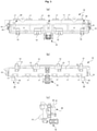
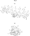
- FIGS. 1A to 1C show a rotating die of a rotary press die according to a first embodiment of the present invention, in which FIG. 1A is a plan view of the rotating die of the first embodiment, FIG. 1B is a front view of the rotating die, and FIG. 1C is a side view of the rotating die, FIG. 2A and 2B show the rotating die of a rotary press die according to the first embodiment of the present invention, in which FIG. 2A is a perspective view of the rotating die and FIG. 2B is a perspective view of the rotating die when viewed from a direction different from that in FIG. 2A , FIGS. 3A and 3B show the rotating die of the rotary press die, in which FIG.
- FIG. 3A is a perspective view when viewed from a direction different from those in FIGS. 2A and 2B and FIG. 3B is a perspective view of the rotating die when viewed from a direction different from those in FIG. 3A and FIGS. 2A and 2B
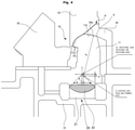
- FIG. 4 is a sectional view showing the configuration of the rotary press die and corresponding to an A - A line in FIG. 2A .
- a rotary press die 10 fixes a rotating rotating die 11 to a fixing table 31 through a rotating block 20, and rotationally drives the rotating die 11 to press-work a panel P with a fixed die 34, a horizontal moving cam 32, and a vertical moving cam 33, and forms a negative angle part Pn on the panel P.
- the rotating die 11 has a size large enough to press an end of a work.
- a positioning distance block 12 and stopper plates 13 and 17 are arranged on the rotating die 11.
- the distance block 12 and the stopper plate 13 are disposed as needed.
- the rotating die 11 is arranged on a bearing 15 such that the rotating die 11 can be rotated by a driven-in shaft 14 and arranged by fixing the bearing 15 to the fixing table 31.
- the distance block 12 determines a stroke amount of a cam
- the stopper plates 13 and 17 regulate a rotating position of the rotating die 11.
- a plurality of (three, in this example) rotating blocks 20 rotatably supporting the rotating die 11 on the fixing table 31 are arranged.
- the rotating block 20 loads the load of the rotating die 11, and the rotating die 11 is rotatably held on the fixing table 31 without occurrence of distortion caused by its own weight or the like.
- the number of arranged rotating blocks 20 is selected as needed.
- the rotating die 11 is rotationally driven at a predetermined angle about a rotating axis Or by driving an air cylinder 16. Although the driven-in shaft 14 positions the rotating die 11 by the rotating axis Or, the position of the rotating die 11 is accessorily determined. In an operation of the rotating die 11, the rotation of the rotating die 11 is held by the rotating blocks 20, the driven-in shaft 14 and the bearing 15 support the rotating die 11 when the rotating die 11 is not held by the rotating blocks 20 when the rotating die 11 is reversely rotated.
- FIG. 5 is an enlarged sectional view showing a rotating block of the rotary press die and a slide surface between a rotating die and a fixed die
- FIGS. 6A to 6C show a rotating block of the rotary press die, in which FIG. 6A is a perspective view showing an entire structure, FIG. 6B is a perspective view showing a fixed piece, and FIG. 6C is a perspective view showing a moving piece.
- the rotating blocks 20 are formed by a fixed piece 21 and a moving piece 22.
- the fixed piece 21 is made of cast iron (FC). As shown in FIG. 6B , on the upper surface of the fixed piece 21, a concave slide surface 23 serving as a cylindrical surface which is concave downward and has the rotating axis Or corresponding to the driven-in shaft 14 of the rotating die 11 as an axis is formed. In the concave slide surface 23, a bolt hole 24 to fix the fixed piece 21 to the fixing table 31 is formed.
- FC cast iron
- the moving piece 22 is formed as a block made of high-tensile brass.
- the high-tensile brass is an alloy containing, for example, copper (Cu) and zinc (Zn) as base materials and combined with aluminum (Al), iron (Fe), manganese (Mn), nickel (Ni), and the like, and is a material having high strength and a high hardness without being thermally treated even though the material is still cast.
- the high-tensile brass has strength (for example, 30 times) higher than that of cast iron and good lubricating property.
- a convex slide surface 25 serving as a cylindrical surface which is convex downward and has the rotating axis Or as an axis is formed.
- a bolt hole 26 to fix the moving piece 22 to the rotating die 11 is formed.
- the fixed piece 21 is fixed to the fixing table 31, and the moving piece 22 is fixed to the rotating die 11 with bolt.
- adjusting thin plates shims are arranged between the fixed piece 21 and the fixing table 31 and between the moving piece 22 and the rotating die 11 to make it possible to finely adjust attaching positions of the parts.
- the fine adjustment can be performed to correct variations caused by distortion of each part and abrasion.
- an opening angle ⁇ between the concave slide surface 23 of the fixed piece 21 and the convex slide surface 25 of the moving piece 22 with reference to the rotating axis Or are set to 90 degrees falling within the range of 80 degrees to 100 degrees. In this manner, even though some force acts on the rotating die 11, the moving piece 22 can be prevented from dropping out from the fixed piece 21.
- the slide surface increases by increasing the opening angle, and a weight per unit area decreases. The slide surface can receive larger force which can reduce friction.
- the opening angle ⁇ between the concave slide surface 23 of the fixed piece 21 and the convex slide surface 25 of the moving piece 22 with reference to the rotating axis Or is given by "x x" when the angle ⁇ is 60 degrees, given by “x” when the angle ⁇ is 70 degrees, given by “x” when the angle ⁇ is 75 degrees, given by “ ⁇ ” when the angle ⁇ is 80 degrees, given by “o ⁇ ” when the angle ⁇ is 85 degrees, and given by "o” when the angle ⁇ is 90 degrees.
- the evaluation "x x” represents “absolutely disapproved”
- “x” represents “disapproved”
- ⁇ ” represents “approved”
- "o ⁇ ” represents "good”
- "o” represents "excellent”.
- the angle ⁇ between the concave slide surface 23 and the convex slide surface 25 with reference to the rotating axis Or must be 80 degrees or more.
- the opening angle ⁇ exceeds 100 degrees
- an effect of preventing the fixed piece 21 from the moving piece 22 when the angle ⁇ exceeds 100 degrees does not increase, and the angle ⁇ which exceeds 100 degrees is not real because costs of materials and manufacturing are high.
- the rotating block 20 used in the embodiment is good in strength and lubricating property because the moving piece 22 is made of high-tensile brass. For this reason, an oil groove need not be formed unlike in a conventional rotating die made of cast iron.
- the high-tensile brass can be mechanically worked at high accuracy.
- a solid lubricant agent for example, graphite can be buried in the concave slide surface 23 of the fixed piece 21 and the convex slide surface 25 of the moving piece 22. In this manner, the contact surface can be prevented from being galled without supplying oil.
- Positional adjustment of the rotating axis Or of the rotating die 11 can be easily performed by interposing an adjusting thin plate (shim) between the fixed piece 21 and the fixing table 31 of the rotating block 20 or the moving piece 22 and the rotating die 11.
- an adjusting thin plate shim
- a rotating-side convex slide surface 11b is continuously formed on a curved blade part 11a forming a negative angle part Pn on the panel P serving as a work.
- the rotating-side convex slide surface 11b is a curved surface which is convex toward the fixed die 34 side and has a radius R1 having a central axis Os as an axis.
- a fixed-side concave side surface 34a facing the rotating-side convex slide surface 11b is formed on the fixed die 34.
- the fixed-side concave side surface 34a is a curved surface which is concave toward the outside and has a radius R2 having the central axis Os as an axis.
- R1 ⁇ R2 is set since the rotating-side convex slide surface 11b and the fixed-side concave side surface 34a do not contact with each other.
- R1 ⁇ R2 is set.
- the following explanation will be executed on the assumption that a dividing surface between the rotating die 11 and the fixed die 34 is called the slice surface S, the axis of the slice surface S is called the central axis Os, and the radius is R.
- the central axis Os is arranged at a position different from that of the rotating axis Or of the rotating die 11, for example, the rotating axis Or is arranged on the curved blade part 11a side forming the negative angle part of the rotating die 11 with reference to the central axis Os.
- the rotating-side convex slide surface 11b and the fixed die 34 moves away from each other to form a gap T.
- the gap T between the rotating-side convex slide surface 11b and the fixed-side concave side surface 34a is largely drawn with exaggeration.
- the rotating-side convex slide surface 11b and the fixed-side concave side surface 34a move in the direction away from each other.
- a smooth operation can be performed without occurrence of contact and friction between the rotating die 11 and the fixed die 34.
- This position may be a position having a height equal to that of, for example, the central axis Os.
- the positional relationship between both the axes can be arbitrarily changed as needed.
- FIGS. 7A to 7D show an operation of the rotary press die, in which FIG. 7A is a sectional view of the rotary press die showing a state of a bottom dead point, FIG. 7B showing a state in which the rotary press die is rotated at 3 degrees, FIG. 7C showing a state in which the rotary press die is rotated at 6 degrees, and FIG. 7D showing a state in which the rotary press die is rotated at 12 degrees.
- FIG. 7A pressing of the panel P is completed.
- the rotating die 11 is sequentially rotated as shown in FIGS. 7B, 7C, and 7D .
- a gap T (clearance) between the rotating die 11 and the fixed die 34 sequentially increases in the order shown in FIG. 7B, FIG. 7C, and FIG. 7D , i.e., 0.62 mm in FIG. 7B , 1.25 mm in FIG. 7C , and 2.54 mm in FIG. 7D .
- 0.62 mm in FIG. 7B 1.25 mm in FIG. 7C
- 2.54 mm in FIG. 7D i.e. 0.62 mm in FIG. 7B , 1.25 mm in FIG. 7C , and 2.54 mm in FIG. 7D .
- the rotating die 11 can smoothly move without contacting with the fixed die 34.
- the convex slide surface 25 of the fixed piece 21 and the concave slide surface 23 of the moving piece 22 contact with each other in a wide opening range, and, large depths of the concave side surface and the convex slide surface can be secured.
- the moving piece can be moved with an accurate central position with reference to the fixed piece. A moving distance of the central position by external force is small. For this reason, the rotating center of the rotating die can be set at high accuracy.
- the moving piece 22 since the moving piece 22 is made of high-tensile brass, the moving piece 22 can have high strength, a high hardness, and good lubricating property.
- the concave slide surface of the moving piece 22 can be worked at high accuracy, the rotation by the rotating block 20 can be smoothly performed.
- the central axis Os of the rotating-side convex slide surface of the rotating die and the fixed-side concave slide surface of the fixed die is set at a position different from that of the rotating axis Or of the rotating die, i.e., on the curved blade part 11a side on which a negative angle part is formed by the rotating die 11 with reference to the rotating axis Or of the rotating die, and the rotating-side convex slide surface 11b and the fixed-side concave side surface 34a move in a direction away from each other to have the gap T when the rotating die 11 is rotated in a retreat direction. For this reason, in rotation of the rotating die 11 on completion of press working, the rotating die 11 can be smoothly moved without contacting the rotating-side convex slide surface 11b and the fixed-side concave slide surface 34a with each other.
- the moving piece 22 is entirely made of high-tensile brass. However, only a portion near the convex slide surface 25 of the moving piece 22 is able to be made of high-tensile brass. A portion near the concave slide surface 23 of the fixed piece 21 or the entire fixed piece 21 may be made of high-tensile brass.
- FIGS. 8A and 8B show a rotary press die according to a second embodiment of the present invention, in which FIG. 8A is a sectional view of the rotary press die in a press completion state and FIG. 8B is a sectional view in a work removing state.
- a rotary press die 40 according to the embodiment forms a panel P having a shape different from that in the first embodiment. For this reason, in the rotary press die 40, the shape of a rotating die 41, the shapes of a horizontal moving cam 52, a vertical moving cam 53, and a fixed doe 54, and the like are different from those in the first embodiment. However, the second embodiment has the same basic configuration as that in the first embodiment.
- This example uses the same rotating block 20 as that in the rotary press die according to the first embodiment in the rotating die 41. More specifically, in the first embodiment, the rotating block 20 is arranged between the rotating die 41 and a fixing table 51, and the rotating die 41 can rotated by using the rotating axis Or as an axis.
- the configuration of the rotating block 20 is the same as that in the first embodiment. More specifically, as shown in FIG. 8A , the rotating block 20 is configured by the fixed piece 21 having the concave slide surface 23 and the moving piece 22 having the convex slide surface 25. An opening angle of the concave slide surface 23 and the convex slide surface 25 with reference to the rotating axis Or is set to 90 degrees.
- the moving piece 22 is made of high-tensile brass.
- the moving piece can move with an accurate central position with reference to the fixed piece.
- a moving distance of the central position by external force is small.
- the rotating center of the rotating die can be set at high accuracy.
- the rotating die 41 in rotation of the rotating die 41 upon completion of press working, the rotating die 41 can be smoothly moved without contacting the rotating-side convex slide surface 41b and the fixed-side concave slide surface 54a with each other.
- the rotating die is configured to be supported by the rotating block and to be rotated.
- the central axis Os of the slice surface S is arranged at a position different from that of the rotating axis Or to make it impossible to contact the rotating-side convex slide surface with the fixed-side concave slide surface.
- the rotary press die according to the present invention can set a rotating center of the rotating die at high accuracy, the rotary press die has industrial applicability on automotive manufacture.
Landscapes
- Engineering & Computer Science (AREA)
- Mechanical Engineering (AREA)
- Chemical & Material Sciences (AREA)
- Materials Engineering (AREA)
- Bending Of Plates, Rods, And Pipes (AREA)
- Mounting, Exchange, And Manufacturing Of Dies (AREA)
- Shaping Metal By Deep-Drawing, Or The Like (AREA)
Applications Claiming Priority (1)
| Application Number | Priority Date | Filing Date | Title |
|---|---|---|---|
| PCT/JP2019/017798 WO2020217430A1 (ja) | 2019-04-25 | 2019-04-25 | 回転式プレス型 |
Publications (2)
| Publication Number | Publication Date |
|---|---|
| EP3960324A1 true EP3960324A1 (de) | 2022-03-02 |
| EP3960324A4 EP3960324A4 (de) | 2023-04-26 |
Family
ID=69997915
Family Applications (1)
| Application Number | Title | Priority Date | Filing Date |
|---|---|---|---|
| EP19806081.6A Pending EP3960324A4 (de) | 2019-04-25 | 2019-04-25 | Rotationsprägestempel |
Country Status (6)
| Country | Link |
|---|---|
| US (1) | US11358201B2 (de) |
| EP (1) | EP3960324A4 (de) |
| JP (1) | JP6656688B1 (de) |
| KR (1) | KR102650173B1 (de) |
| CN (1) | CN112135698B (de) |
| WO (1) | WO2020217430A1 (de) |
Families Citing this family (1)
| Publication number | Priority date | Publication date | Assignee | Title |
|---|---|---|---|---|
| CN113857311B (zh) * | 2021-09-08 | 2024-05-03 | 南通瑞斯电子有限公司 | 一种s弹齿加工设备 |
Family Cites Families (15)
| Publication number | Priority date | Publication date | Assignee | Title |
|---|---|---|---|---|
| JPS62296914A (ja) * | 1986-06-18 | 1987-12-24 | Honda Motor Co Ltd | ベンド金型装置 |
| JP3196615B2 (ja) * | 1995-10-24 | 2001-08-06 | トヨタ車体株式会社 | プレス金型 |
| JPH11226672A (ja) * | 1998-02-13 | 1999-08-24 | Toyota Motor Corp | プレス用金型 |
| JPH11254038A (ja) * | 1998-03-16 | 1999-09-21 | Your Business:Kk | プレス用金型 |
| JP2002219527A (ja) * | 2001-01-22 | 2002-08-06 | Toyota Motor Corp | プレス金型および負角部の離型方法 |
| JP3505157B2 (ja) * | 2001-03-05 | 2004-03-08 | ユミックス株式会社 | 負角成形型 |
| KR100513535B1 (ko) * | 2003-09-24 | 2005-09-07 | 현대자동차주식회사 | 복합 캠형 프레스 장치 |
| JP2005118788A (ja) * | 2003-10-14 | 2005-05-12 | Umix Co Ltd | 袋状ワーク加工用負角成形型 |
| US7523634B2 (en) * | 2004-08-24 | 2009-04-28 | Helical Cam, Llc. | Forming die having filler cam assembly |
| CN201271695Y (zh) * | 2008-09-10 | 2009-07-15 | 盘起工业(大连)有限公司 | 正装高效斜楔机构 |
| JP4597254B1 (ja) * | 2009-10-16 | 2010-12-15 | 株式会社ユアビジネス | 回動体の回動構造 |
| JP2012110903A (ja) * | 2010-11-19 | 2012-06-14 | Oiles Corp | 突き上げカム装置 |
| CN103801623B (zh) * | 2014-03-05 | 2015-12-02 | 唐山轨道客车有限责任公司 | 弯曲冲压模具 |
| CN105414327B (zh) * | 2015-12-14 | 2017-11-07 | 苏州广硕精密电子有限公司 | 一种冲压机模具更换装置 |
| CN106140978A (zh) * | 2016-08-19 | 2016-11-23 | 苏州市华宁机械制造有限公司 | 一种冲压模具用斜楔机构 |
-
2019
- 2019-04-25 KR KR1020197021970A patent/KR102650173B1/ko active Active
- 2019-04-25 EP EP19806081.6A patent/EP3960324A4/de active Pending
- 2019-04-25 JP JP2019523126A patent/JP6656688B1/ja active Active
- 2019-04-25 WO PCT/JP2019/017798 patent/WO2020217430A1/ja not_active Ceased
- 2019-04-25 CN CN201980001761.XA patent/CN112135698B/zh active Active
- 2019-04-25 US US16/619,153 patent/US11358201B2/en active Active
Also Published As
| Publication number | Publication date |
|---|---|
| EP3960324A4 (de) | 2023-04-26 |
| US11358201B2 (en) | 2022-06-14 |
| JP6656688B1 (ja) | 2020-03-04 |
| JPWO2020217430A1 (ja) | 2021-05-06 |
| KR102650173B1 (ko) | 2024-03-21 |
| WO2020217430A1 (ja) | 2020-10-29 |
| CN112135698B (zh) | 2023-07-14 |
| US20210354185A1 (en) | 2021-11-18 |
| CN112135698A (zh) | 2020-12-25 |
| KR20210113455A (ko) | 2021-09-16 |
Similar Documents
| Publication | Publication Date | Title |
|---|---|---|
| EP1097010B1 (de) | Fliegend auf der matrize montierte nockeneinheit | |
| JP5230743B2 (ja) | スライダ受け手段を備えたくさび駆動装置 | |
| EP1791663B1 (de) | Universalgleitnocken | |
| US8042374B2 (en) | Multi-tool technology | |
| JP2003500215A (ja) | 自己案内型パンチ/ダイセット | |
| US20040025561A1 (en) | V-belt drive | |
| US8225702B2 (en) | Stripping device | |
| US11358201B2 (en) | Rotary press die | |
| JP2002337000A (ja) | 工作機械用案内装置 | |
| JP2016087683A (ja) | プレス成形型 | |
| EP1763423B1 (de) | Umkehrbarer gleitststempelhalter für ein stempelwechselhaltewerkzeug | |
| JP3760308B2 (ja) | 圧造成形機 | |
| JPH11285740A (ja) | 回転カム軸受構造 | |
| CN223531280U (zh) | 一种拱形滑块结构的吊装斜楔 | |
| CN119343471A (zh) | 凸轮装置 | |
| CN223616574U (zh) | 冲压设备 | |
| CN223185442U (zh) | 一种轴承锻造用锻压模具 | |
| CN108043933B (zh) | 一种自动翻孔脱模机构及机床 | |
| EP1699579B1 (de) | Geteiltes formwerkzeug mit mindestens zwei formwerkzeugkomponenten | |
| JP2019069477A (ja) | カム装置 | |
| CN219425404U (zh) | 一种冲孔凹模的快换结构 | |
| KR200444471Y1 (ko) | 프로그레시브 금형 | |
| CN211219433U (zh) | 翻转工装 | |
| JP6868244B2 (ja) | 摺動部材、及び、それを備えたカム装置 | |
| JP2022001373A (ja) | プレス加工用金型工具 |
Legal Events
| Date | Code | Title | Description |
|---|---|---|---|
| STAA | Information on the status of an ep patent application or granted ep patent |
Free format text: STATUS: UNKNOWN |
|
| STAA | Information on the status of an ep patent application or granted ep patent |
Free format text: STATUS: THE INTERNATIONAL PUBLICATION HAS BEEN MADE |
|
| PUAI | Public reference made under article 153(3) epc to a published international application that has entered the european phase |
Free format text: ORIGINAL CODE: 0009012 |
|
| STAA | Information on the status of an ep patent application or granted ep patent |
Free format text: STATUS: REQUEST FOR EXAMINATION WAS MADE |
|
| 17P | Request for examination filed |
Effective date: 20191129 |
|
| AK | Designated contracting states |
Kind code of ref document: A1 Designated state(s): AL AT BE BG CH CY CZ DE DK EE ES FI FR GB GR HR HU IE IS IT LI LT LU LV MC MK MT NL NO PL PT RO RS SE SI SK SM TR |
|
| DAV | Request for validation of the european patent (deleted) | ||
| DAX | Request for extension of the european patent (deleted) | ||
| RIN1 | Information on inventor provided before grant (corrected) |
Inventor name: KINOSHITA, TADATOSHI |
|
| RIC1 | Information provided on ipc code assigned before grant |
Ipc: B21D 37/12 20060101ALI20221108BHEP Ipc: B21D 5/01 20060101ALI20221108BHEP Ipc: B21D 37/08 20060101AFI20221108BHEP |
|
| A4 | Supplementary search report drawn up and despatched |
Effective date: 20230324 |
|
| RIC1 | Information provided on ipc code assigned before grant |
Ipc: B21D 37/12 20060101ALI20230320BHEP Ipc: B21D 5/01 20060101ALI20230320BHEP Ipc: B21D 37/08 20060101AFI20230320BHEP |
|
| STAA | Information on the status of an ep patent application or granted ep patent |
Free format text: STATUS: EXAMINATION IS IN PROGRESS |
|
| 17Q | First examination report despatched |
Effective date: 20250723 |