EP3960682A1 - Ascenseur autobloquant auto-grimpant - Google Patents
Ascenseur autobloquant auto-grimpant Download PDFInfo
- Publication number
- EP3960682A1 EP3960682A1 EP21194399.8A EP21194399A EP3960682A1 EP 3960682 A1 EP3960682 A1 EP 3960682A1 EP 21194399 A EP21194399 A EP 21194399A EP 3960682 A1 EP3960682 A1 EP 3960682A1
- Authority
- EP
- European Patent Office
- Prior art keywords
- supports
- platform
- support
- nearby structure
- extending
- Prior art date
- Legal status (The legal status is an assumption and is not a legal conclusion. Google has not performed a legal analysis and makes no representation as to the accuracy of the status listed.)
- Granted
Links
Images


Classifications
-
- B—PERFORMING OPERATIONS; TRANSPORTING
- B66—HOISTING; LIFTING; HAULING
- B66B—ELEVATORS; ESCALATORS OR MOVING WALKWAYS
- B66B9/00—Kinds or types of lifts in, or associated with, buildings or other structures
- B66B9/02—Kinds or types of lifts in, or associated with, buildings or other structures actuated mechanically otherwise than by rope or cable
-
- B—PERFORMING OPERATIONS; TRANSPORTING
- B66—HOISTING; LIFTING; HAULING
- B66B—ELEVATORS; ESCALATORS OR MOVING WALKWAYS
- B66B1/00—Control systems of elevators in general
- B66B1/02—Control systems without regulation, i.e. without retroactive action
-
- B—PERFORMING OPERATIONS; TRANSPORTING
- B66—HOISTING; LIFTING; HAULING
- B66B—ELEVATORS; ESCALATORS OR MOVING WALKWAYS
- B66B11/00—Main component parts of lifts in, or associated with, buildings or other structures
- B66B11/02—Cages, i.e. cars
-
- B—PERFORMING OPERATIONS; TRANSPORTING
- B66—HOISTING; LIFTING; HAULING
- B66B—ELEVATORS; ESCALATORS OR MOVING WALKWAYS
- B66B11/00—Main component parts of lifts in, or associated with, buildings or other structures
- B66B11/04—Driving gear ; Details thereof, e.g. seals
- B66B11/0423—Driving gear ; Details thereof, e.g. seals actuated pneumatically or hydraulically
-
- B—PERFORMING OPERATIONS; TRANSPORTING
- B66—HOISTING; LIFTING; HAULING
- B66B—ELEVATORS; ESCALATORS OR MOVING WALKWAYS
- B66B7/00—Other common features of elevators
- B66B7/02—Guideways; Guides
-
- B—PERFORMING OPERATIONS; TRANSPORTING
- B66—HOISTING; LIFTING; HAULING
- B66B—ELEVATORS; ESCALATORS OR MOVING WALKWAYS
- B66B7/00—Other common features of elevators
- B66B7/02—Guideways; Guides
- B66B7/04—Riding means, e.g. Shoes, Rollers, between car and guiding means, e.g. rails, ropes
- B66B7/046—Rollers
-
- B—PERFORMING OPERATIONS; TRANSPORTING
- B66—HOISTING; LIFTING; HAULING
- B66B—ELEVATORS; ESCALATORS OR MOVING WALKWAYS
- B66B9/00—Kinds or types of lifts in, or associated with, buildings or other structures
- B66B9/02—Kinds or types of lifts in, or associated with, buildings or other structures actuated mechanically otherwise than by rope or cable
- B66B9/027—Kinds or types of lifts in, or associated with, buildings or other structures actuated mechanically otherwise than by rope or cable by rope climbing devices
-
- B—PERFORMING OPERATIONS; TRANSPORTING
- B66—HOISTING; LIFTING; HAULING
- B66B—ELEVATORS; ESCALATORS OR MOVING WALKWAYS
- B66B9/00—Kinds or types of lifts in, or associated with, buildings or other structures
- B66B9/04—Kinds or types of lifts in, or associated with, buildings or other structures actuated pneumatically or hydraulically
-
- E—FIXED CONSTRUCTIONS
- E04—BUILDING
- E04G—SCAFFOLDING; FORMS; SHUTTERING; BUILDING IMPLEMENTS OR AIDS, OR THEIR USE; HANDLING BUILDING MATERIALS ON THE SITE; REPAIRING, BREAKING-UP OR OTHER WORK ON EXISTING BUILDINGS
- E04G3/00—Scaffolds essentially supported by building constructions, e.g. adjustable in height
- E04G3/28—Mobile scaffolds; Scaffolds with mobile platforms
- E04G2003/286—Mobile scaffolds; Scaffolds with mobile platforms mobile vertically
Definitions
- Elevator systems are useful for carrying passengers and items between different levels of a building.
- Many elevator systems are traction-based and include traction ropes that suspend the elevator car and a counterweight.
- a machine causes movement of a traction sheave that, in turn, causes movement of the traction ropes for moving the elevator car as desired.
- Other elevator systems are hydraulic and include an expanding cylinder that raises or lowers the elevator car.
- Each type of elevator system has limitations.
- the ropes of traction-based systems introduce significant weight and expense in high-rise building installations.
- the traction ropes may also experience sway under various conditions.
- One limitation on hydraulic elevator systems is that they are not practical for high rise buildings.
- Elevator system providers are always striving to increase the efficiencies and economies of elevator systems. For example, various proposals have been made to include more than one elevator car in a single hoistway to increase the passenger-carrying capacity while occupying less building space. Such proposals are often considered too complicated and have not been widely adopted.
- An illustrative example embodiment of an elevator system includes a platform and a plurality of supports configured to selectively engage a nearby structure.
- the plurality of supports include at least a first support and a second support.
- the first and second supports alternate between engaging the nearby structure to support the platform while the other one of the supports is disengaged from the nearby structure.
- At least one of the first and second supports is configured to move relative to the platform while engaging the nearby structure to cause vertical movement of the platform.
- At least one of the first and second supports extends or contracts while engaging the nearby structure to cause the vertical movement of the platform.
- each of the supports has a vertical stroke corresponding to a distance between a fully contracted position and a fully extended position of the support, and both of the first and second supports simultaneously engage the nearby structure while extending or contracting along at least a portion of the vertical stroke of the support such that both of the first and second supports simultaneously cause the vertical movement of the platform.
- the first support extends over the portion of the vertical stroke, and the second support contracts over the portion of the vertical stroke.
- one of the first and second supports engages the nearby structure while extending or contracting along another portion of the vertical stroke of the support simultaneously with the other of the second and first supports contracting or extending along another portion of the vertical stroke of the support while being disengaged from the nearby structure.
- At least some of the supports each comprise an articulating robotic arm.
- At least some of the supports each comprise a pressurized cylinder.
- the supports each comprise a grip near one end of the support configured to engage the nearby structure.
- the grips are respectively configured to engage at least one type of feature selected from the group of features consisting of a wall, a pole, a rail, a rope, a belt, a rung, a groove, a flange, a tooth and a rib.
- the first support is situated relative to the platform for extending above the platform, and the second support is situated relative to the platform for extending beneath the platform.
- the first and second supports each engage the nearby structure adjacent a first side of the platform
- the platform includes at least one follower on a second side of the platform that is configured to follow along a nearby structure adjacent the second side of the platform.
- the at least one follower comprises a plurality of rollers.
- the plurality of supports includes at least two of the supports situated relative to the platform for extending above the platform and at least two others of the supports situated relative to the platform for extending beneath the platform.
- the platform is part of an elevator car including a cabin configured to accommodate a plurality of passengers.
- An illustrative example embodiment of a method of controlling movement of an elevator platform includes: selectively engaging a nearby structure using supports associated with the platform, alternating between engaging the nearby structure using at least a first one of the supports or at least a second one of the supports to support the platform while the other one of the supports is disengaged from the nearby structure, and moving at least one of the first and second supports relative to the platform while engaging the nearby structure to cause vertical movement of the platform.
- the moving comprises extending or contracting the at least one of the first and second supports while engaging the nearby structure to cause the vertical movement of the platform.
- each of the supports has a vertical stroke corresponding to a distance between a fully contracted position and a fully extended position of the support
- the method comprises simultaneously engaging the nearby structure while extending or contracting both of the first and second supports along at least a portion of the vertical stroke of the support such that both of the first and second one of the supports simultaneously cause the vertical movement of the platform.
- An example embodiment having at least one feature of the method of any of the previous paragraphs includes extending the first one of the supports over the portion of the vertical stroke simultaneously with contracting the second one of the supports over the portion of the vertical stroke.
- An example embodiment having at least one feature of the method of any of the previous paragraphs includes engaging the nearby structure by one of the first and second supports while extending or contracting along another portion of the vertical stroke of the support simultaneously with disengaging the other of the second and first supports from the nearby structure while contracting or extending the support along another portion of the vertical stroke of the support.
- An example embodiment having at least one feature of the method of any of the previous paragraphs includes extending the first one of the supports above the platform, and extending the second one of the supports beneath the platform.
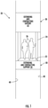
- FIG. 1 schematically illustrates selected portions of an elevator system 20.
- a platform 22 is part of an elevator car 24 that includes a cabin configured to accommodate a plurality of passengers 26.
- a plurality of supports 30 are configured to move relative to the platform in a manner that causes vertical movement of the platform 22.
- a first support 32 is situated above the platform 22 and a second support 34 is situated beneath the platform 22.
- the plurality of supports 30 provide stability and support for the platform 22 and selectively cause vertical movement of the platform 22 in a manner that introduces various efficiencies and design opportunities within an elevator system.
- the plurality of supports 30 are configured to sequentially and alternately engage a nearby structure 40 and to extend or contract to cause vertical movement of the platform 22.
- the first support 32 and the second support 34 sequentially alternate between engaging the nearby structure 40 to support the platform 22 while the other support is disengaged from the nearby structure 40.
- At least the one of the supports 30 that engages the nearby structure 40 moves relative to the platform 22 to cause vertical movement of the platform 22.
- the movement of the supports 30 relative to the platform 22 includes extending and contracting.
- the first support 32 is schematically shown in an extended position or condition while the second support 34 is schematically illustrated in a contracted position or condition.
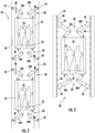
- FIG 2 illustrates one example arrangement of an elevator system 20 that includes multiple platforms 22 within a single hoistway.
- each platform 22 is like that shown in Figure 1 and part of an elevator car 24.
- the plurality of supports 30 includes first supports 32A and 32B situated to extend above the elevator car 24.
- Second supports 34A and 34B are situated for extending beneath the elevator car 24.
- Each of the supports includes a gripper 42 configured to engage the nearby structure 40, which includes the interior hoistway walls in this example.
- the supports 30 in the illustrated example embodiment each comprise an articulated robotic arm. Coordinated extending and contracting movement of the robotic arm supports 30 achieves desired vertical movement of the elevator car 24 as the first supports 32A and 32B and the second supports 34A and 34B sequentially alternate between engaging the hoistway walls 40 to support the platform 22 while the other supports are disengaged from the hoistway walls 40.
- the first supports 32A and 32B may first be extended above the elevator car 24 and engage the hoistway walls 40.
- the second supports 34A and 34B may then disengage from the hoistway walls 40 and contract upward toward the platform 22.
- the first supports 32A and 32B contract, pulling the elevator car 24 vertically upward.
- the second supports 34A and 34B engage the hoistway walls 40 and then extend, further propelling the elevator car 24 vertically upward. While the second supports 34A and 34B are engaged with the hoistway walls 40, the first supports 34A and 34B can disengage and extend again above the elevator car 24. Such sequential and alternating engagement and disengagement from the nearby structure 40 while extending or contracting, allows the supports 30 to secure the platform 22 against undesired movement and achieve the desired vertical movement.
- each of the supports 30 has a vertical stroke corresponding to a distance between a fully contracted position and a fully extended position of the support 30.
- the first supports 32A and 32B can simultaneously engage the nearby structure 40 while the second supports 34A and 34B also engage the nearby structure 40.
- All of the first supports 32A, 32B and the second supports 34A, 34B can simultaneously extend or contract along at least a portion of the vertical stroke of the support such that the first supports 32A, 32B and the second supports 34A, 34B simultaneously cause vertical movement of the platform 22.
- the first supports 32A, 32B extend over the portion of the vertical stroke while the second supports 34A, 34B contract over a corresponding portion of their vertical stroke.
- At least the first supports 32A, 32B or the second supports 34A, 34B engages the nearby structure 40 while extending or contracting along another portion of the vertical stroke of those supports.
- the other of the second supports 34A, 34B or the first supports 32A, 32B contracts or extends along another portion of the vertical stroke of those supports while being disengaged from the nearby structure 40.
- a variety of timings are possible between the engagement and disengagement of the supports 30 from the nearby structure 40 and a variety of percentages of the vertical stroke of each support may be used while engaged with the nearby structure 40 to achieve desired movement of the platform 22.
- Such coordinated movement can facilitate relatively quick vertical movement of the platform 22 while always having at least some of the supports 30 engaged with the nearby structure 40 to support the platform 22 in a way that controls any vertical movement of the platform.
- One feature of the example arrangement shown in Figure 2 is that multiple elevator cars 24 are independently moveable within a single hoistway.
- the extending and contracting supports 30 make it possible to incorporate as many elevator cars within a single hoistway as desired without requiring a complicated arrangement of traction ropes, for example.
- an elevator system designed according to an embodiment of this invention it is, at least in some respects, easier to incorporate multiple cars within a single hoistway and to move them independent of each other.
- Figure 3 illustrates an arrangement in which the nearby structure 40 includes climbing features 44 that the grips 42 engage for purposes of supporting the platform 22 in a desired position and moving the platform 22 when desired.
- the features 44 may take a variety of forms depending on the particular configuration of the elevator system 20 and the grips 42 are configured in a corresponding manner to facilitate reliable engagement.
- the features 44 comprise a plurality of rungs, grooves, or ribs.
- Such features 44 may be incorporated into or secured to the building structure, such as the interior hoistway walls.
- the features 44 are part of a self-standing or self-supporting structure that is situated in a manner that accommodates the loads of the elevator system 20.
- the grips 42 may include hooks, clamps, or electromagnets, for example, to achieve reliable engagement with the features 44.
- Figure 4 schematically illustrates another example embodiment in which the elevator system 20 does not require a hoistway.
- the nearby structure 40 comprises a plurality of elongate vertical members that are engaged by the grips 42 of the supports 30 for purposes of climbing along the elongate vertical members to achieve the desired vertical movement of the platform 22.
- Structures 40 in such an embodiment may include a rail, a pole, a rope, or a belt, for example.
- Such structures may include climbing features 44, such as teeth, flanges, ribs or grooves.
- the nearby structure 40 includes two elongate vertical members as illustrated in Figure 4 , other embodiments include a single pole or rope, for example, that the extending and contracting supports 30 engage.
- Figure 5 illustrates another example arrangement of an elevator system 20 including extending and contracting supports 30.
- a single first support 32 and a single second support 34 are situated near a first side 46 of the elevator car 24.
- the grips 42 on the supports 32 and 34 engage a nearby structure 40, such as an interior hoistway wall adjacent the first side 46.
- the grips 42 include a friction material configured to frictionally engage the nearby structure 40.
- At least one follower is situated near an opposite, second side 48 of the elevator car 24.
- the follower includes a plurality of rollers 50 that follow along the nearby structure 40 that is adjacent the second side 48 of the elevator car 24.
- rollers 50 in some such embodiments follow a channel, groove or vertically extending rib that is part of, or secured to, the hoistway wall 40.
- Horizontal forces imposed by the supports 30 and frictional engagement with the nearby structure provides the support needed for the platform 22 and allows for accomplishing desired vertical movement.
- Figure 6 schematically illustrates another example elevator system configuration in which the supports 30 include pressurized cylinders that extend and contract in a sequential and alternating manner that is coordinated to achieve vertical movement of the platform 22.
- the pressurized cylinders in some embodiments are hydraulic. In other embodiments the pressurized cylinders are pneumatic.
- the grips 42 in some such embodiments are electromagnetic and engage a metallic surface on the nearby structure 40 when energized. Having grips 42 that are selectively energized to engage the nearby structure 40 allows for the pressurized cylinders of the supports 30 to extend in a vertical direction while selectively engaging or disengaging from the nearby structure 40.
- the platforms 22 in the illustrations are associated with a cabin.
- Other platform configurations can be used with supports 30 for various purposes in an elevator system.
- a platform may be configured for installation of elevator system components and used for positioning equipment or workers in a hoistway during installation or maintenance.
- Other platform configurations are useful for rescue operations to carry an individual along a hoistway into a position to attend to passengers in a car that is stopped in the hoistway.
- the platform and supports operate independently of the passenger-carrying car of the elevator system.
Landscapes
- Engineering & Computer Science (AREA)
- Structural Engineering (AREA)
- Automation & Control Theory (AREA)
- Mechanical Engineering (AREA)
- Civil Engineering (AREA)
- Types And Forms Of Lifts (AREA)
- Cage And Drive Apparatuses For Elevators (AREA)
- Lift-Guide Devices, And Elevator Ropes And Cables (AREA)
Applications Claiming Priority (1)
| Application Number | Priority Date | Filing Date | Title |
|---|---|---|---|
| US17/008,695 US11814266B2 (en) | 2020-09-01 | 2020-09-01 | Self-climbing self-locking elevator |
Publications (2)
| Publication Number | Publication Date |
|---|---|
| EP3960682A1 true EP3960682A1 (fr) | 2022-03-02 |
| EP3960682B1 EP3960682B1 (fr) | 2024-02-14 |
Family
ID=77595463
Family Applications (1)
| Application Number | Title | Priority Date | Filing Date |
|---|---|---|---|
| EP21194399.8A Active EP3960682B1 (fr) | 2020-09-01 | 2021-09-01 | Ascenseur autobloquant auto-grimpant |
Country Status (4)
| Country | Link |
|---|---|
| US (1) | US11814266B2 (fr) |
| EP (1) | EP3960682B1 (fr) |
| KR (1) | KR20220029459A (fr) |
| CN (1) | CN114104914B (fr) |
Families Citing this family (2)
| Publication number | Priority date | Publication date | Assignee | Title |
|---|---|---|---|---|
| EP4001196A1 (fr) * | 2020-11-13 | 2022-05-25 | Philippe Henneau | Système et procédés d'élévateur pneumatique durables |
| CN117569556B (zh) * | 2024-01-15 | 2024-03-19 | 山东泽宇钢制品有限公司 | 大型储罐施工用的综合工作平台 |
Citations (2)
| Publication number | Priority date | Publication date | Assignee | Title |
|---|---|---|---|---|
| CN109399432A (zh) * | 2018-11-23 | 2019-03-01 | 燕山大学 | 一种自爬升井道作业平台 |
| WO2020142001A1 (fr) * | 2019-01-04 | 2020-07-09 | Em Services Pte Ltd | Plate-forme mobile |
Family Cites Families (11)
| Publication number | Priority date | Publication date | Assignee | Title |
|---|---|---|---|---|
| US4660678A (en) * | 1984-09-27 | 1987-04-28 | Spider A/S | Service suspension basket arrangement |
| HU213428B (en) * | 1992-10-27 | 1997-06-30 | Inventio Ag | Self propelled device mainly for passanger carriing |
| US5579865A (en) * | 1994-02-23 | 1996-12-03 | Butler; J. Frank | Scaffold |
| DK1706636T3 (en) * | 2003-12-30 | 2018-11-05 | Pp Energy Aps | Device to enable access to a ground level construction |
| DE102005030335A1 (de) * | 2005-06-29 | 2007-01-04 | Peri Gmbh | Kletterzylinder einer Selbstkletterschalung |
| PL2593391T3 (pl) * | 2010-07-16 | 2017-10-31 | Marc Keersmaekers | Moduł podnośnikowy do podnoszenia i opuszczania rusztowania |
| TWM425118U (en) * | 2011-08-17 | 2012-03-21 | jun-liang Li | Self-propelled lifting working platform |
| DE102012104993A1 (de) * | 2012-06-11 | 2013-12-12 | Thyssenkrupp Elevator Ag | Verfahren und Montagesystem zur Montage von Aufzugskomponenten |
| DE102016205956A1 (de) * | 2016-04-08 | 2017-10-12 | Peri Gmbh | Selbstklettersystem, Selbstklettereinheit sowie Verfahren zum Umsetzen einer solchen Selbstklettereinheit an einem Betonbaukörper |
| US10494235B2 (en) * | 2016-12-06 | 2019-12-03 | General Electric Company | Crane system and an associated method thereof |
| CN108979114B (zh) * | 2017-05-31 | 2020-12-04 | 深圳市特辰科技股份有限公司 | 一种全自动剪叉式机器人爬架 |
-
2020
- 2020-09-01 US US17/008,695 patent/US11814266B2/en active Active
-
2021
- 2021-07-20 CN CN202110819034.3A patent/CN114104914B/zh not_active Expired - Fee Related
- 2021-08-26 KR KR1020210113079A patent/KR20220029459A/ko not_active Withdrawn
- 2021-09-01 EP EP21194399.8A patent/EP3960682B1/fr active Active
Patent Citations (2)
| Publication number | Priority date | Publication date | Assignee | Title |
|---|---|---|---|---|
| CN109399432A (zh) * | 2018-11-23 | 2019-03-01 | 燕山大学 | 一种自爬升井道作业平台 |
| WO2020142001A1 (fr) * | 2019-01-04 | 2020-07-09 | Em Services Pte Ltd | Plate-forme mobile |
Also Published As
| Publication number | Publication date |
|---|---|
| EP3960682B1 (fr) | 2024-02-14 |
| CN114104914A (zh) | 2022-03-01 |
| KR20220029459A (ko) | 2022-03-08 |
| US11814266B2 (en) | 2023-11-14 |
| US20220063959A1 (en) | 2022-03-03 |
| CN114104914B (zh) | 2023-11-28 |
Similar Documents
| Publication | Publication Date | Title |
|---|---|---|
| US8291568B2 (en) | Method of installing an elevator | |
| US10501289B2 (en) | Method and arrangement for installing an elevator | |
| US10252890B2 (en) | Method for installing an elevator in the construction phase of a building | |
| US8881872B2 (en) | Method of installing an elevator | |
| EP2804828B1 (fr) | Procédé et système d'ascenseur | |
| US20120023863A1 (en) | Method And Elevator Arrangement | |
| EP3816088B1 (fr) | Agencement d'ascenseur auto-grimpant à utiliser lors de la construction d'un bâtiment | |
| EP3960682B1 (fr) | Ascenseur autobloquant auto-grimpant | |
| HK1220171A1 (zh) | 导轨安装装置和用於安装导轨的方法 | |
| US12043519B2 (en) | Elevator system | |
| WO2013175054A9 (fr) | Agencement d'ascenseur et procédé | |
| US10351389B2 (en) | Elevator | |
| US9533860B2 (en) | Elevator arrangement and a method | |
| EP3093263A1 (fr) | Dispositif et un procédé de transport de matériau dans une cage d'ascenseur | |
| CN110040602B (zh) | 用于双层电梯的电梯厢悬挂组件 | |
| AU2013361851B2 (en) | Maintenance method for a lift | |
| WO2020142001A1 (fr) | Plate-forme mobile | |
| US20240253950A1 (en) | Arrangement and method for installing guide rails of an elevator | |
| EP1016616A1 (fr) | Systéme de guidage de cabine d' ascenseur | |
| JPH0480188A (ja) | ダブルデッキエレベータ | |
| JP5468029B2 (ja) | エレベータ装置 | |
| SU1386544A1 (ru) | Строительный подъемник | |
| HK1195763B (en) | An elevator arrangement and a method | |
| HK1166301A (en) | Method and elevator arrangement |
Legal Events
| Date | Code | Title | Description |
|---|---|---|---|
| PUAI | Public reference made under article 153(3) epc to a published international application that has entered the european phase |
Free format text: ORIGINAL CODE: 0009012 |
|
| STAA | Information on the status of an ep patent application or granted ep patent |
Free format text: STATUS: THE APPLICATION HAS BEEN PUBLISHED |
|
| AK | Designated contracting states |
Kind code of ref document: A1 Designated state(s): AL AT BE BG CH CY CZ DE DK EE ES FI FR GB GR HR HU IE IS IT LI LT LU LV MC MK MT NL NO PL PT RO RS SE SI SK SM TR |
|
| STAA | Information on the status of an ep patent application or granted ep patent |
Free format text: STATUS: REQUEST FOR EXAMINATION WAS MADE |
|
| 17P | Request for examination filed |
Effective date: 20220831 |
|
| RBV | Designated contracting states (corrected) |
Designated state(s): AL AT BE BG CH CY CZ DE DK EE ES FI FR GB GR HR HU IE IS IT LI LT LU LV MC MK MT NL NO PL PT RO RS SE SI SK SM TR |
|
| GRAP | Despatch of communication of intention to grant a patent |
Free format text: ORIGINAL CODE: EPIDOSNIGR1 |
|
| STAA | Information on the status of an ep patent application or granted ep patent |
Free format text: STATUS: GRANT OF PATENT IS INTENDED |
|
| INTG | Intention to grant announced |
Effective date: 20231010 |
|
| GRAS | Grant fee paid |
Free format text: ORIGINAL CODE: EPIDOSNIGR3 |
|
| GRAA | (expected) grant |
Free format text: ORIGINAL CODE: 0009210 |
|
| STAA | Information on the status of an ep patent application or granted ep patent |
Free format text: STATUS: THE PATENT HAS BEEN GRANTED |
|
| AK | Designated contracting states |
Kind code of ref document: B1 Designated state(s): AL AT BE BG CH CY CZ DE DK EE ES FI FR GB GR HR HU IE IS IT LI LT LU LV MC MK MT NL NO PL PT RO RS SE SI SK SM TR |
|
| REG | Reference to a national code |
Ref country code: GB Ref legal event code: FG4D |
|
| REG | Reference to a national code |
Ref country code: CH Ref legal event code: EP |
|
| REG | Reference to a national code |
Ref country code: DE Ref legal event code: R096 Ref document number: 602021009345 Country of ref document: DE |
|
| REG | Reference to a national code |
Ref country code: IE Ref legal event code: FG4D |
|
| REG | Reference to a national code |
Ref country code: LT Ref legal event code: MG9D |
|
| REG | Reference to a national code |
Ref country code: NL Ref legal event code: MP Effective date: 20240214 |
|
| PG25 | Lapsed in a contracting state [announced via postgrant information from national office to epo] |
Ref country code: IS Free format text: LAPSE BECAUSE OF FAILURE TO SUBMIT A TRANSLATION OF THE DESCRIPTION OR TO PAY THE FEE WITHIN THE PRESCRIBED TIME-LIMIT Effective date: 20240614 |
|
| PG25 | Lapsed in a contracting state [announced via postgrant information from national office to epo] |
Ref country code: LT Free format text: LAPSE BECAUSE OF FAILURE TO SUBMIT A TRANSLATION OF THE DESCRIPTION OR TO PAY THE FEE WITHIN THE PRESCRIBED TIME-LIMIT Effective date: 20240214 |
|
| PG25 | Lapsed in a contracting state [announced via postgrant information from national office to epo] |
Ref country code: GR Free format text: LAPSE BECAUSE OF FAILURE TO SUBMIT A TRANSLATION OF THE DESCRIPTION OR TO PAY THE FEE WITHIN THE PRESCRIBED TIME-LIMIT Effective date: 20240515 |
|
| REG | Reference to a national code |
Ref country code: AT Ref legal event code: MK05 Ref document number: 1656900 Country of ref document: AT Kind code of ref document: T Effective date: 20240214 |
|
| PG25 | Lapsed in a contracting state [announced via postgrant information from national office to epo] |
Ref country code: RS Free format text: LAPSE BECAUSE OF FAILURE TO SUBMIT A TRANSLATION OF THE DESCRIPTION OR TO PAY THE FEE WITHIN THE PRESCRIBED TIME-LIMIT Effective date: 20240514 Ref country code: NL Free format text: LAPSE BECAUSE OF FAILURE TO SUBMIT A TRANSLATION OF THE DESCRIPTION OR TO PAY THE FEE WITHIN THE PRESCRIBED TIME-LIMIT Effective date: 20240214 Ref country code: HR Free format text: LAPSE BECAUSE OF FAILURE TO SUBMIT A TRANSLATION OF THE DESCRIPTION OR TO PAY THE FEE WITHIN THE PRESCRIBED TIME-LIMIT Effective date: 20240214 |
|
| PG25 | Lapsed in a contracting state [announced via postgrant information from national office to epo] |
Ref country code: ES Free format text: LAPSE BECAUSE OF FAILURE TO SUBMIT A TRANSLATION OF THE DESCRIPTION OR TO PAY THE FEE WITHIN THE PRESCRIBED TIME-LIMIT Effective date: 20240214 |
|
| PG25 | Lapsed in a contracting state [announced via postgrant information from national office to epo] |
Ref country code: AT Free format text: LAPSE BECAUSE OF FAILURE TO SUBMIT A TRANSLATION OF THE DESCRIPTION OR TO PAY THE FEE WITHIN THE PRESCRIBED TIME-LIMIT Effective date: 20240214 |
|
| PG25 | Lapsed in a contracting state [announced via postgrant information from national office to epo] |
Ref country code: RS Free format text: LAPSE BECAUSE OF FAILURE TO SUBMIT A TRANSLATION OF THE DESCRIPTION OR TO PAY THE FEE WITHIN THE PRESCRIBED TIME-LIMIT Effective date: 20240514 Ref country code: NO Free format text: LAPSE BECAUSE OF FAILURE TO SUBMIT A TRANSLATION OF THE DESCRIPTION OR TO PAY THE FEE WITHIN THE PRESCRIBED TIME-LIMIT Effective date: 20240514 Ref country code: NL Free format text: LAPSE BECAUSE OF FAILURE TO SUBMIT A TRANSLATION OF THE DESCRIPTION OR TO PAY THE FEE WITHIN THE PRESCRIBED TIME-LIMIT Effective date: 20240214 Ref country code: LT Free format text: LAPSE BECAUSE OF FAILURE TO SUBMIT A TRANSLATION OF THE DESCRIPTION OR TO PAY THE FEE WITHIN THE PRESCRIBED TIME-LIMIT Effective date: 20240214 Ref country code: IS Free format text: LAPSE BECAUSE OF FAILURE TO SUBMIT A TRANSLATION OF THE DESCRIPTION OR TO PAY THE FEE WITHIN THE PRESCRIBED TIME-LIMIT Effective date: 20240614 Ref country code: HR Free format text: LAPSE BECAUSE OF FAILURE TO SUBMIT A TRANSLATION OF THE DESCRIPTION OR TO PAY THE FEE WITHIN THE PRESCRIBED TIME-LIMIT Effective date: 20240214 Ref country code: GR Free format text: LAPSE BECAUSE OF FAILURE TO SUBMIT A TRANSLATION OF THE DESCRIPTION OR TO PAY THE FEE WITHIN THE PRESCRIBED TIME-LIMIT Effective date: 20240515 Ref country code: FI Free format text: LAPSE BECAUSE OF FAILURE TO SUBMIT A TRANSLATION OF THE DESCRIPTION OR TO PAY THE FEE WITHIN THE PRESCRIBED TIME-LIMIT Effective date: 20240214 Ref country code: ES Free format text: LAPSE BECAUSE OF FAILURE TO SUBMIT A TRANSLATION OF THE DESCRIPTION OR TO PAY THE FEE WITHIN THE PRESCRIBED TIME-LIMIT Effective date: 20240214 Ref country code: BG Free format text: LAPSE BECAUSE OF FAILURE TO SUBMIT A TRANSLATION OF THE DESCRIPTION OR TO PAY THE FEE WITHIN THE PRESCRIBED TIME-LIMIT Effective date: 20240214 Ref country code: AT Free format text: LAPSE BECAUSE OF FAILURE TO SUBMIT A TRANSLATION OF THE DESCRIPTION OR TO PAY THE FEE WITHIN THE PRESCRIBED TIME-LIMIT Effective date: 20240214 |
|
| PG25 | Lapsed in a contracting state [announced via postgrant information from national office to epo] |
Ref country code: PL Free format text: LAPSE BECAUSE OF FAILURE TO SUBMIT A TRANSLATION OF THE DESCRIPTION OR TO PAY THE FEE WITHIN THE PRESCRIBED TIME-LIMIT Effective date: 20240214 Ref country code: PT Free format text: LAPSE BECAUSE OF FAILURE TO SUBMIT A TRANSLATION OF THE DESCRIPTION OR TO PAY THE FEE WITHIN THE PRESCRIBED TIME-LIMIT Effective date: 20240614 |
|
| PG25 | Lapsed in a contracting state [announced via postgrant information from national office to epo] |
Ref country code: SE Free format text: LAPSE BECAUSE OF FAILURE TO SUBMIT A TRANSLATION OF THE DESCRIPTION OR TO PAY THE FEE WITHIN THE PRESCRIBED TIME-LIMIT Effective date: 20240214 Ref country code: PT Free format text: LAPSE BECAUSE OF FAILURE TO SUBMIT A TRANSLATION OF THE DESCRIPTION OR TO PAY THE FEE WITHIN THE PRESCRIBED TIME-LIMIT Effective date: 20240614 Ref country code: PL Free format text: LAPSE BECAUSE OF FAILURE TO SUBMIT A TRANSLATION OF THE DESCRIPTION OR TO PAY THE FEE WITHIN THE PRESCRIBED TIME-LIMIT Effective date: 20240214 Ref country code: LV Free format text: LAPSE BECAUSE OF FAILURE TO SUBMIT A TRANSLATION OF THE DESCRIPTION OR TO PAY THE FEE WITHIN THE PRESCRIBED TIME-LIMIT Effective date: 20240214 |
|
| PG25 | Lapsed in a contracting state [announced via postgrant information from national office to epo] |
Ref country code: DK Free format text: LAPSE BECAUSE OF FAILURE TO SUBMIT A TRANSLATION OF THE DESCRIPTION OR TO PAY THE FEE WITHIN THE PRESCRIBED TIME-LIMIT Effective date: 20240214 |
|
| PG25 | Lapsed in a contracting state [announced via postgrant information from national office to epo] |
Ref country code: SM Free format text: LAPSE BECAUSE OF FAILURE TO SUBMIT A TRANSLATION OF THE DESCRIPTION OR TO PAY THE FEE WITHIN THE PRESCRIBED TIME-LIMIT Effective date: 20240214 |
|
| PG25 | Lapsed in a contracting state [announced via postgrant information from national office to epo] |
Ref country code: EE Free format text: LAPSE BECAUSE OF FAILURE TO SUBMIT A TRANSLATION OF THE DESCRIPTION OR TO PAY THE FEE WITHIN THE PRESCRIBED TIME-LIMIT Effective date: 20240214 Ref country code: CZ Free format text: LAPSE BECAUSE OF FAILURE TO SUBMIT A TRANSLATION OF THE DESCRIPTION OR TO PAY THE FEE WITHIN THE PRESCRIBED TIME-LIMIT Effective date: 20240214 |
|
| PG25 | Lapsed in a contracting state [announced via postgrant information from national office to epo] |
Ref country code: SK Free format text: LAPSE BECAUSE OF FAILURE TO SUBMIT A TRANSLATION OF THE DESCRIPTION OR TO PAY THE FEE WITHIN THE PRESCRIBED TIME-LIMIT Effective date: 20240214 |
|
| PG25 | Lapsed in a contracting state [announced via postgrant information from national office to epo] |
Ref country code: SM Free format text: LAPSE BECAUSE OF FAILURE TO SUBMIT A TRANSLATION OF THE DESCRIPTION OR TO PAY THE FEE WITHIN THE PRESCRIBED TIME-LIMIT Effective date: 20240214 Ref country code: SK Free format text: LAPSE BECAUSE OF FAILURE TO SUBMIT A TRANSLATION OF THE DESCRIPTION OR TO PAY THE FEE WITHIN THE PRESCRIBED TIME-LIMIT Effective date: 20240214 Ref country code: RO Free format text: LAPSE BECAUSE OF FAILURE TO SUBMIT A TRANSLATION OF THE DESCRIPTION OR TO PAY THE FEE WITHIN THE PRESCRIBED TIME-LIMIT Effective date: 20240214 Ref country code: EE Free format text: LAPSE BECAUSE OF FAILURE TO SUBMIT A TRANSLATION OF THE DESCRIPTION OR TO PAY THE FEE WITHIN THE PRESCRIBED TIME-LIMIT Effective date: 20240214 Ref country code: DK Free format text: LAPSE BECAUSE OF FAILURE TO SUBMIT A TRANSLATION OF THE DESCRIPTION OR TO PAY THE FEE WITHIN THE PRESCRIBED TIME-LIMIT Effective date: 20240214 Ref country code: CZ Free format text: LAPSE BECAUSE OF FAILURE TO SUBMIT A TRANSLATION OF THE DESCRIPTION OR TO PAY THE FEE WITHIN THE PRESCRIBED TIME-LIMIT Effective date: 20240214 |
|
| REG | Reference to a national code |
Ref country code: DE Ref legal event code: R097 Ref document number: 602021009345 Country of ref document: DE |
|
| PG25 | Lapsed in a contracting state [announced via postgrant information from national office to epo] |
Ref country code: IT Free format text: LAPSE BECAUSE OF FAILURE TO SUBMIT A TRANSLATION OF THE DESCRIPTION OR TO PAY THE FEE WITHIN THE PRESCRIBED TIME-LIMIT Effective date: 20240214 |
|
| PLBE | No opposition filed within time limit |
Free format text: ORIGINAL CODE: 0009261 |
|
| STAA | Information on the status of an ep patent application or granted ep patent |
Free format text: STATUS: NO OPPOSITION FILED WITHIN TIME LIMIT |
|
| PG25 | Lapsed in a contracting state [announced via postgrant information from national office to epo] |
Ref country code: IT Free format text: LAPSE BECAUSE OF FAILURE TO SUBMIT A TRANSLATION OF THE DESCRIPTION OR TO PAY THE FEE WITHIN THE PRESCRIBED TIME-LIMIT Effective date: 20240214 |
|
| 26N | No opposition filed |
Effective date: 20241115 |
|
| REG | Reference to a national code |
Ref country code: DE Ref legal event code: R119 Ref document number: 602021009345 Country of ref document: DE |
|
| PG25 | Lapsed in a contracting state [announced via postgrant information from national office to epo] |
Ref country code: MC Free format text: LAPSE BECAUSE OF FAILURE TO SUBMIT A TRANSLATION OF THE DESCRIPTION OR TO PAY THE FEE WITHIN THE PRESCRIBED TIME-LIMIT Effective date: 20240214 Ref country code: SI Free format text: LAPSE BECAUSE OF FAILURE TO SUBMIT A TRANSLATION OF THE DESCRIPTION OR TO PAY THE FEE WITHIN THE PRESCRIBED TIME-LIMIT Effective date: 20240214 |
|
| REG | Reference to a national code |
Ref country code: CH Ref legal event code: PL |
|
| PG25 | Lapsed in a contracting state [announced via postgrant information from national office to epo] |
Ref country code: LU Free format text: LAPSE BECAUSE OF NON-PAYMENT OF DUE FEES Effective date: 20240901 |
|
| PG25 | Lapsed in a contracting state [announced via postgrant information from national office to epo] |
Ref country code: DE Free format text: LAPSE BECAUSE OF NON-PAYMENT OF DUE FEES Effective date: 20250401 |
|
| REG | Reference to a national code |
Ref country code: BE Ref legal event code: MM Effective date: 20240930 |
|
| PG25 | Lapsed in a contracting state [announced via postgrant information from national office to epo] |
Ref country code: BE Free format text: LAPSE BECAUSE OF NON-PAYMENT OF DUE FEES Effective date: 20240930 |
|
| PG25 | Lapsed in a contracting state [announced via postgrant information from national office to epo] |
Ref country code: FR Free format text: LAPSE BECAUSE OF NON-PAYMENT OF DUE FEES Effective date: 20240930 |
|
| PG25 | Lapsed in a contracting state [announced via postgrant information from national office to epo] |
Ref country code: CH Free format text: LAPSE BECAUSE OF NON-PAYMENT OF DUE FEES Effective date: 20240930 |
|
| PG25 | Lapsed in a contracting state [announced via postgrant information from national office to epo] |
Ref country code: IE Free format text: LAPSE BECAUSE OF NON-PAYMENT OF DUE FEES Effective date: 20240901 |
|
| PG25 | Lapsed in a contracting state [announced via postgrant information from national office to epo] |
Ref country code: CY Free format text: LAPSE BECAUSE OF FAILURE TO SUBMIT A TRANSLATION OF THE DESCRIPTION OR TO PAY THE FEE WITHIN THE PRESCRIBED TIME-LIMIT; INVALID AB INITIO Effective date: 20210901 |
|
| PG25 | Lapsed in a contracting state [announced via postgrant information from national office to epo] |
Ref country code: HU Free format text: LAPSE BECAUSE OF FAILURE TO SUBMIT A TRANSLATION OF THE DESCRIPTION OR TO PAY THE FEE WITHIN THE PRESCRIBED TIME-LIMIT; INVALID AB INITIO Effective date: 20210901 |