EP3960973A1 - Carrosserie de véhicule - Google Patents
Carrosserie de véhicule Download PDFInfo
- Publication number
- EP3960973A1 EP3960973A1 EP21184057.4A EP21184057A EP3960973A1 EP 3960973 A1 EP3960973 A1 EP 3960973A1 EP 21184057 A EP21184057 A EP 21184057A EP 3960973 A1 EP3960973 A1 EP 3960973A1
- Authority
- EP
- European Patent Office
- Prior art keywords
- guide
- lower panel
- vehicle body
- section
- sectional door
- Prior art date
- Legal status (The legal status is an assumption and is not a legal conclusion. Google has not performed a legal analysis and makes no representation as to the accuracy of the status listed.)
- Granted
Links
Images


Classifications
-
- E—FIXED CONSTRUCTIONS
- E05—LOCKS; KEYS; WINDOW OR DOOR FITTINGS; SAFES
- E05D—HINGES OR SUSPENSION DEVICES FOR DOORS, WINDOWS OR WINGS
- E05D15/00—Suspension arrangements for wings
- E05D15/16—Suspension arrangements for wings for wings sliding vertically more or less in their own plane
- E05D15/24—Suspension arrangements for wings for wings sliding vertically more or less in their own plane consisting of parts connected at their edges
-
- B—PERFORMING OPERATIONS; TRANSPORTING
- B60—VEHICLES IN GENERAL
- B60J—WINDOWS, WINDSCREENS, NON-FIXED ROOFS, DOORS, OR SIMILAR DEVICES FOR VEHICLES; REMOVABLE EXTERNAL PROTECTIVE COVERINGS SPECIALLY ADAPTED FOR VEHICLES
- B60J5/00—Doors
- B60J5/10—Doors arranged at the vehicle rear
- B60J5/12—Doors arranged at the vehicle rear slidable; foldable
- B60J5/14—Doors arranged at the vehicle rear slidable; foldable of roller-blind type made of rigid elements
-
- E—FIXED CONSTRUCTIONS
- E05—LOCKS; KEYS; WINDOW OR DOOR FITTINGS; SAFES
- E05D—HINGES OR SUSPENSION DEVICES FOR DOORS, WINDOWS OR WINGS
- E05D13/00—Accessories for sliding or lifting wings, e.g. pulleys, safety catches
- E05D13/10—Counterbalance devices
- E05D13/12—Counterbalance devices with springs
- E05D13/1253—Counterbalance devices with springs with canted-coil torsion springs
- E05D13/1261—Counterbalance devices with springs with canted-coil torsion springs specially adapted for overhead wings
-
- E—FIXED CONSTRUCTIONS
- E05—LOCKS; KEYS; WINDOW OR DOOR FITTINGS; SAFES
- E05D—HINGES OR SUSPENSION DEVICES FOR DOORS, WINDOWS OR WINGS
- E05D15/00—Suspension arrangements for wings
- E05D15/16—Suspension arrangements for wings for wings sliding vertically more or less in their own plane
- E05D15/24—Suspension arrangements for wings for wings sliding vertically more or less in their own plane consisting of parts connected at their edges
- E05D15/244—Upper part guiding means
- E05D15/248—Upper part guiding means with lever arms for producing an additional movement
-
- E—FIXED CONSTRUCTIONS
- E05—LOCKS; KEYS; WINDOW OR DOOR FITTINGS; SAFES
- E05D—HINGES OR SUSPENSION DEVICES FOR DOORS, WINDOWS OR WINGS
- E05D15/00—Suspension arrangements for wings
- E05D15/16—Suspension arrangements for wings for wings sliding vertically more or less in their own plane
- E05D15/22—Suspension arrangements for wings for wings sliding vertically more or less in their own plane allowing an additional movement
- E05D2015/225—Suspension arrangements for wings for wings sliding vertically more or less in their own plane allowing an additional movement specially adapted for overhead wings
-
- E—FIXED CONSTRUCTIONS
- E05—LOCKS; KEYS; WINDOW OR DOOR FITTINGS; SAFES
- E05Y—INDEXING SCHEME ASSOCIATED WITH SUBCLASSES E05D AND E05F, RELATING TO CONSTRUCTION ELEMENTS, ELECTRIC CONTROL, POWER SUPPLY, POWER SIGNAL OR TRANSMISSION, USER INTERFACES, MOUNTING OR COUPLING, DETAILS, ACCESSORIES, AUXILIARY OPERATIONS NOT OTHERWISE PROVIDED FOR, APPLICATION THEREOF
- E05Y2900/00—Application of doors, windows, wings or fittings thereof
- E05Y2900/50—Application of doors, windows, wings or fittings thereof for vehicles
- E05Y2900/516—Application of doors, windows, wings or fittings thereof for vehicles for trucks or trailers
Definitions
- the present invention relates to a vehicle body with a sectional door which can be moved to open and close an opening in a loading space and has a large number of panels which are pivotably mounted on one another and which can be moved on opposite sides via guide means along a guide which in the area of the opening has an im Substantially vertical section, in the upper area of the loading space a substantially horizontal section as a storage section for the sectional door and an arcuate section in between, wherein a spring shaft is provided for biasing the sectional door into an open position, with the lower panel arranged on the ground side being pivotable in a closed position is held on a running part that can be moved along the guide.
- the DE 20 2015 105 844 U1 discloses a vehicle body in which a loading space can be closed by a movable sectional door.
- the sectional door comprises a large number of panels which are connected to one another in an articulated manner and which are prestressed into an open position via a spring shaft.
- a spring break safety device is also provided on the spring shaft.
- the pivotably mounted panels can be moved along a guide, with the lower panel, which is arranged on the floor in a closed position, having a guide roller on its radially outer side in the arc-shaped section, which can roll on a lintel or a beam on the top of the opening is.
- at least one guide roller can also be held on the lintel or beam, which can be rolled on the lower panel when this is arranged on the arcuate section. This prevents an outer side of the lower panel from hitting the beam or lintel and the lower panel can be moved smoothly to the maximum opening position.
- the at least one guide roller is arranged between the lintel or beam on the one hand and the bottom panel on the other hand.
- several guide rollers are arranged or fixed along the length of the lower panel, so that the panel is supported at several points at the same time and can be moved along the beam or lintel by the guide rollers.
- a gap is defined between the bottom panel and the support or beam via the guide rollers, in which other structures can be placed, such as operating aids, for example a handle, loops or a latch or lock.
- a lintel or beam is preferably arranged at the top of the sectional door, with the sectional door preferably being arranged completely behind the lintel or beam in an open position when viewed horizontally.
- the maximum opening height at the hold is dictated by the lower edge of the lintel or beam and the sectional door can be positioned with the lower panel higher or substantially level with the lower end of the lintel.
- the running part comprises a fastening section which is fixed to the panel, and a guide section which is held pivotably on the fastening section and which can be moved along the guide via a roller or a sliding element.
- the running part can thus be designed as a two-armed articulated lever which is fixed on the one hand on the panel and on the other hand can be moved along the guide.
- the bottom panel is preferably movable on opposite sides along a guide via such a runner.
- the lower panel has a groove into which part of the guide section with a holder for the roller can be inserted.
- the panels are preferably made from one or more extruded profiles, in particular from plastic or metal, so that a groove made integrally in the profile can be used to fix the holder for the roller.
- the profile also has one or more hollow chambers for high torsional rigidity.
- the holder is fixed to the panel between an outer plane formed by the outer surface of the panel and an inner plane formed by an inner surface of the panel.
- the lower panel is arranged on the arcuate portion of the guide, and the lower panel is arranged with a lower end higher than a lower end of the runner.
- the lower panel can thus be positioned higher in the opening position, deviating from the guide, in order to increase the maximum opening height for loading and unloading.
- the bottom panel is preferably biased into the raised position by a spring member. Thereby, the trajectory of movement of the bottom panel at the arcuate portion can be more accurately controlled.
- the spring element can be supported with a first part on the guide section and with a second part on the fastening section of the running part.
- a pull element is preferably fixed to the lower panel, with which the sectional door can be moved into an open position via the spring shaft.
- the lower panel is automatically pivoted relative to the guide in the region of the arcuate section of the guide via the pulling element, for example a cable pull, without the need for additional components such as springs or drives, would have to be provided.
- the tension element By pulling on the tension element, the lower panel is arranged higher than the pivotable guide section of the runner.
- an actuating element for example a handle or a loop, for moving the sectional door from the open position to the closed position is fixed on the lower panel.
- the user can then, for example, pull the sectional door down via the actuating element until the sectional door is locked in a closed position via a lock, which can also be fixed to the lower panel.
- a stepped holder is preferably provided on the running part, on which a roller is rotatably mounted at one end and at the other end of which the holder is inserted, for example, into an opening on the guide section of the running part.
- the holder can be fixed in a central area of the lower panel, while the roller is arranged spaced from the opening toward a lower end of the guide. This enables the holder to be fixed in a stable manner in a central area of the lower panel and at the same time an arrangement of the lower roller in the area of a lower edge of the lower panel for optimized guidance.
- a lower end of the panel In an open position of the sectional door, a lower end of the panel can be arranged at least 5 mm, preferably between 10 mm and 50 mm, higher than a roller on the running part. In a closed position, the roller on the running part can be in an extension of the lower panel.
- a vehicle body 1 comprises a sectional door 2, which has a multiplicity of panels 3 which are connected to one another in an articulated manner and which, in a closed position, cover an opening in a loading space. In the closed position, a bottom panel 4 arranged on the floor is locked via a lock 5, which fixes the sectional door 2 to a floor of a vehicle.
- the sectional door 2 is arranged between two posts 6, which are connected to each other in the upper area via a lintel 7 or a beam and specify the maximum opening to the loading space.
- the sectional door 2 can be moved from a substantially vertical closed position into a horizontal open position in which the sectional door 2 is arranged below a roof 9 .
- FIG 2 the guide 10 for the sectional door 2 is shown, with further structural parts of the vehicle body having been omitted.
- a guide 10 On both sides of the sectional door 2 is a guide 10 having a vertical portion 11 adjacent to the opening, a horizontal portion for storing the sectional door 2 in an open position, and an arcuate portion 13 between the vertical portion 11 and the horizontal portion 12.
- the guide 10 can be formed by individual rail sections on which guide means such as rollers or sliding elements are guided.
- a handle 16 and a cable pull anchor 17 are fixed to the lower panel 4 and are each connected to a spring shaft 8 via a cable pull.
- the sectional door 2 can be moved via a spring shaft 8 which is arranged above the sectional door 2 in the closed position and which prestresses the sectional door 2 into an open position via a tension element.
- the spring shaft 8 can For example, be designed as in the DE 20 2015 105 884 U1 is described, in which a spring fracture safety device for the spring shaft is also disclosed.
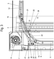
- FIG 3 the lower panel 4 of the sectional door 2 is shown in a position just before the maximum opening position.
- the lower panel 4 has been moved to the arcuate section 13 via a pulling element, for example a cable pull, which pulls the sectional door 2 into the open position via the spring shaft 8 .
- the lower panel 4 is held on the guide 10 such that it can be moved via upper rollers 15 .
- the lower panel 4 is not directly connected to the curved section 13 of the guide 10 via a roller, but via a running part 20.
- the running part 20 has a plate-shaped fastening section 21 which is fixed to the inside of the lower panel 4, and a guide portion 22 pivotally or rotatably connected thereto, to which a roller 23 or a slider is fixed.
- the lower panel 4 can be pivoted relative to the guide section 22, so that a lower end of the lower panel 4 is arranged higher than a lower end on the guide section 22 or the roller 23.
- a guide roller 40 is fixed via a holder 41 on the lower panel 4 on the radially outer side in relation to the arcuate section 13 , the guide roller 40 being able to roll on the lintel 7 .
- the guide roller 40 prevents the outside of the lower panel 4 from hitting the lintel 7 and ensures that the lower panel 4 can be moved easily along the lower edge of the lintel 7, even if the lower panel 4 executes a pivoting movement.
- the guide roller 40 can optionally be made of an elastic material so that impact forces can be at least partially absorbed.
- the lower panel 4 is biased upwards via a spring element 31 in order to arrange it higher than the lower edge of the lintel after driving over the lintel 7 . In the open position, the bottom panel 4 is located behind the lintel 7, looking horizontally towards the lintel 7, and does not protrude downwards therefrom.
- An actuating element in the form of a handle or a loop is also fixed on the inside of the lower panel 4 , by means of which the sectional door 2 can be moved into the closed position against the force of the spring shaft 8 . If the user on the actuator substantially in vertical Pulling direction, the sectional door 2 can be moved because the bottom panel 4 is in the region of the arcuate section 13 of the guide 10 . By pulling on the actuating element, the lower panel 4 can be pivoted relative to the guide section 22 in order then to pull the lower panel 4 downwards from the arcuate section 13 when a stop is reached. The effort required to close the sectional door 2 can thus be kept low, and the user can also pull the bottom panel 4 essentially downwards via the actuating element in the usual way and does not have to apply any force in the horizontal direction.
- FIG. 1 shows a bottom panel 4 with a running part 20 which has a plate-shaped fastening section 21 which is fixed to the bottom panel 4.
- FIG. A guide section 22 is articulated on the fastening section 21, the essentially plate-shaped guide section 22 having a part 18 protruding towards the lower panel 4, on which an opening 30 for the holder 24 ( 3 ) is designed to support a roller 23.
- the protruding part 18 is arranged in a groove 19 on the lower panel 4 so that the opening 30 for inserting the holder 24 is arranged within the two planes defined by an inner surface and an outer surface of the lower panel 4 .
- the panels 3 and 4 are made from one or more extruded profiles of plastic or metal so that the groove 19 is integrally formed.
- One or more hollow chambers can be provided at a distance from the groove 19, so that the panels 4 have a high level of stability while using little material.
- the guide section 22 is prestressed in a pivoting direction by a spring element 31 so that the running part 20 pivots the lower panel 4 upwards when it reaches the arcuate section 13 .
- the fastening section 21 comprises openings 25 for the insertion of fastening means and for fixing to the lower panel 4.
- a sleeve 26 is formed integrally with the fastening section 21, and further sleeves 27 are formed integrally with the guide section 22, so that through the sleeves 26 and 27 an axis 28 can be pushed through, which is secured in the axial direction by a securing element 29 .
- the fastening section 21 and the guide section 22 are connected to one another in an articulated manner.
- a spring element 31 is provided, which is supported with a first part 32 on the guide section 22 and with one or more parts 33 on the fastening section 21.
- the spring element 31 comprises two sections with windings, one section with windings between one of the sleeves 26 and one of the sleeves 27 is arranged.
- other spring elements 31 can also be used to prestress the guide section 22 relative to the fastening section 21 .
- the guide roller 40 with the holder 41 is shown in detail.
- the holder 41 is made of a U-shaped part made of plastic or metal, two webs 45 with openings being formed integrally with the holder 41, through which an axle 43 can be pushed.
- openings 42 for fasteners are provided to fix the holder 41 to the bottom panel 4.
- the guide roller 40 is rotatably mounted on the axle 43 and is positioned at a distance from the webs 45 via two spacers 44 .
- a securing element 46 is mounted on the axle 43 so that the axial movement of the axle 43 is limited at the webs 45 .
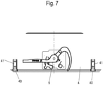
- FIG 7 the bottom panel 4 is shown in plan view.
- a plurality of holders 41 with guide rollers 40 can be provided on the lower panel 4, which are arranged on either side of the central lock 5.
- the number of guide rollers 40 and holders 41 can be selected depending on the length of the bottom panel.
- the guide rollers 40 are held on the bottom panel 4 . It is also possible to rotatably mount the guide rollers 40 partially or completely on the lintel 7 or beam, so that they can be rolled on the lower panel 4 when this is moved on the arcuate section 13 .
Landscapes
- Engineering & Computer Science (AREA)
- Mechanical Engineering (AREA)
- Lock And Its Accessories (AREA)
Applications Claiming Priority (1)
| Application Number | Priority Date | Filing Date | Title |
|---|---|---|---|
| DE102020122203.3A DE102020122203A1 (de) | 2020-08-25 | 2020-08-25 | Fahrzeugaufbau |
Publications (3)
| Publication Number | Publication Date |
|---|---|
| EP3960973A1 true EP3960973A1 (fr) | 2022-03-02 |
| EP3960973C0 EP3960973C0 (fr) | 2024-02-28 |
| EP3960973B1 EP3960973B1 (fr) | 2024-02-28 |
Family
ID=76829358
Family Applications (1)
| Application Number | Title | Priority Date | Filing Date |
|---|---|---|---|
| EP21184057.4A Active EP3960973B1 (fr) | 2020-08-25 | 2021-07-06 | Carrosserie de véhicule |
Country Status (2)
| Country | Link |
|---|---|
| EP (1) | EP3960973B1 (fr) |
| DE (1) | DE102020122203A1 (fr) |
Citations (5)
| Publication number | Priority date | Publication date | Assignee | Title |
|---|---|---|---|---|
| US20120125545A1 (en) | 2010-11-22 | 2012-05-24 | Ehrlich Rodney P | Hinged bottom roller assembly and counterbalance mechanism for overhead door |
| US20150083348A1 (en) | 2013-09-24 | 2015-03-26 | Whiting Door Manufacturing Corporation | Snubber devices for use in roll-up door assemblies |
| DE202015105884U1 (de) | 2015-11-04 | 2015-11-12 | Schulz Farben- Und Lackfabrik Gmbh | Anlage zur Herstellung von Bautenfarben und Halbfabrikaten zu Bautenfarben und Bautenfarben |
| DE202015105844U1 (de) | 2015-11-03 | 2015-12-15 | Wihag Fahrzeugbausysteme Gmbh | Fahrzeugaufbau |
| WO2019072654A1 (fr) * | 2017-10-10 | 2019-04-18 | Hörmann KG Brockhagen | Élément de porte inférieur comportant un support à rouleau pivotant |
-
2020
- 2020-08-25 DE DE102020122203.3A patent/DE102020122203A1/de not_active Withdrawn
-
2021
- 2021-07-06 EP EP21184057.4A patent/EP3960973B1/fr active Active
Patent Citations (5)
| Publication number | Priority date | Publication date | Assignee | Title |
|---|---|---|---|---|
| US20120125545A1 (en) | 2010-11-22 | 2012-05-24 | Ehrlich Rodney P | Hinged bottom roller assembly and counterbalance mechanism for overhead door |
| US20150083348A1 (en) | 2013-09-24 | 2015-03-26 | Whiting Door Manufacturing Corporation | Snubber devices for use in roll-up door assemblies |
| DE202015105844U1 (de) | 2015-11-03 | 2015-12-15 | Wihag Fahrzeugbausysteme Gmbh | Fahrzeugaufbau |
| DE202015105884U1 (de) | 2015-11-04 | 2015-11-12 | Schulz Farben- Und Lackfabrik Gmbh | Anlage zur Herstellung von Bautenfarben und Halbfabrikaten zu Bautenfarben und Bautenfarben |
| WO2019072654A1 (fr) * | 2017-10-10 | 2019-04-18 | Hörmann KG Brockhagen | Élément de porte inférieur comportant un support à rouleau pivotant |
Also Published As
| Publication number | Publication date |
|---|---|
| EP3960973C0 (fr) | 2024-02-28 |
| DE102020122203A1 (de) | 2022-03-03 |
| EP3960973B1 (fr) | 2024-02-28 |
Similar Documents
| Publication | Publication Date | Title |
|---|---|---|
| EP1383967B1 (fr) | Couvercle pour un systeme d'ecoulement des eaux | |
| DE10014760B4 (de) | Heckscheibenrollo mit gefederten Rollen | |
| DE69705662T2 (de) | Rollvorrichtung für Schiebetüren, Fenster oder ähnliches | |
| EP3478533B1 (fr) | Dispositif de réglage en longueur et siège de véhicule | |
| DE19846308C2 (de) | Abdicht- und Verriegelungsvorrichtung für Fenster oder Türen | |
| EP3911824B1 (fr) | Ferrure pour porte coulissante et meuble | |
| DE69115918T2 (de) | Vorrichtung für fahrzeugladeplattformen mit rungenhaltern | |
| DE102007042365A1 (de) | Führungseinheit für einen höhenverstellbaren Ladeboden und Kraftfahrzeug mit einer solchen Führungseinheit und einem höhenverstellbaren Ladeboden | |
| DE9310246U1 (de) | Kraftfahrzeugsitz mit einer zwischen dem Fahrzeugboden und dem Sitzkissen angeordneten Schublade | |
| DE3423504A1 (de) | Befestigungsvorrichtung | |
| DE3906682A1 (de) | Seil-umlenkvorrichtung | |
| DE102019124732A1 (de) | Auszugsführung | |
| EP3960973B1 (fr) | Carrosserie de véhicule | |
| EP3655612B1 (fr) | Store plissé avec rail de guidage télescopique | |
| DE102020114966A1 (de) | Schiebeabdeckung für eine Dachöffnung eines Nutzfahrzeug-Laderaums | |
| EP3789573B1 (fr) | Carrosserie de véhicule | |
| EP2505744A2 (fr) | Plaque de fermeture pour un battant de porte ou de fenêtre déposé d'un dormant | |
| DE19834700B4 (de) | Vorrichtung zum Verschließen einer Wandöffnung | |
| DE102020102186A1 (de) | Verschlusssystem zur lösbaren Befestigung einer Runge an ein Nutzfahrzeug | |
| EP0679788A1 (fr) | Chariot ainsi qu'ensemble coulissant et rail | |
| EP2837549B1 (fr) | Rancher de véhicule utilitaire | |
| DE19835684C2 (de) | Verfahrbare Türflügelanordnung | |
| DE102012210584A1 (de) | Schiebetüranlage | |
| EP1820423A1 (fr) | Console pour des lattes réglable en hauteur dans un sommier à latttes | |
| DE3936164C2 (fr) |
Legal Events
| Date | Code | Title | Description |
|---|---|---|---|
| PUAI | Public reference made under article 153(3) epc to a published international application that has entered the european phase |
Free format text: ORIGINAL CODE: 0009012 |
|
| STAA | Information on the status of an ep patent application or granted ep patent |
Free format text: STATUS: THE APPLICATION HAS BEEN PUBLISHED |
|
| STAA | Information on the status of an ep patent application or granted ep patent |
Free format text: STATUS: REQUEST FOR EXAMINATION WAS MADE |
|
| AK | Designated contracting states |
Kind code of ref document: A1 Designated state(s): AL AT BE BG CH CY CZ DE DK EE ES FI FR GB GR HR HU IE IS IT LI LT LU LV MC MK MT NL NO PL PT RO RS SE SI SK SM TR |
|
| 17P | Request for examination filed |
Effective date: 20220207 |
|
| RBV | Designated contracting states (corrected) |
Designated state(s): AL AT BE BG CH CY CZ DE DK EE ES FI FR GB GR HR HU IE IS IT LI LT LU LV MC MK MT NL NO PL PT RO RS SE SI SK SM TR |
|
| GRAP | Despatch of communication of intention to grant a patent |
Free format text: ORIGINAL CODE: EPIDOSNIGR1 |
|
| STAA | Information on the status of an ep patent application or granted ep patent |
Free format text: STATUS: GRANT OF PATENT IS INTENDED |
|
| INTG | Intention to grant announced |
Effective date: 20231113 |
|
| GRAS | Grant fee paid |
Free format text: ORIGINAL CODE: EPIDOSNIGR3 |
|
| GRAA | (expected) grant |
Free format text: ORIGINAL CODE: 0009210 |
|
| STAA | Information on the status of an ep patent application or granted ep patent |
Free format text: STATUS: THE PATENT HAS BEEN GRANTED |
|
| AK | Designated contracting states |
Kind code of ref document: B1 Designated state(s): AL AT BE BG CH CY CZ DE DK EE ES FI FR GB GR HR HU IE IS IT LI LT LU LV MC MK MT NL NO PL PT RO RS SE SI SK SM TR |
|
| REG | Reference to a national code |
Ref country code: GB Ref legal event code: FG4D Free format text: NOT ENGLISH |
|
| REG | Reference to a national code |
Ref country code: CH Ref legal event code: EP |
|
| REG | Reference to a national code |
Ref country code: DE Ref legal event code: R096 Ref document number: 502021002806 Country of ref document: DE |
|
| REG | Reference to a national code |
Ref country code: IE Ref legal event code: FG4D Free format text: LANGUAGE OF EP DOCUMENT: GERMAN |
|
| U01 | Request for unitary effect filed |
Effective date: 20240311 |
|
| U07 | Unitary effect registered |
Designated state(s): AT BE BG DE DK EE FI FR IT LT LU LV MT NL PT SE SI Effective date: 20240319 |
|
| PG25 | Lapsed in a contracting state [announced via postgrant information from national office to epo] |
Ref country code: IS Free format text: LAPSE BECAUSE OF FAILURE TO SUBMIT A TRANSLATION OF THE DESCRIPTION OR TO PAY THE FEE WITHIN THE PRESCRIBED TIME-LIMIT Effective date: 20240628 |
|
| PG25 | Lapsed in a contracting state [announced via postgrant information from national office to epo] |
Ref country code: GR Free format text: LAPSE BECAUSE OF FAILURE TO SUBMIT A TRANSLATION OF THE DESCRIPTION OR TO PAY THE FEE WITHIN THE PRESCRIBED TIME-LIMIT Effective date: 20240529 |
|
| PG25 | Lapsed in a contracting state [announced via postgrant information from national office to epo] |
Ref country code: RS Free format text: LAPSE BECAUSE OF FAILURE TO SUBMIT A TRANSLATION OF THE DESCRIPTION OR TO PAY THE FEE WITHIN THE PRESCRIBED TIME-LIMIT Effective date: 20240528 Ref country code: HR Free format text: LAPSE BECAUSE OF FAILURE TO SUBMIT A TRANSLATION OF THE DESCRIPTION OR TO PAY THE FEE WITHIN THE PRESCRIBED TIME-LIMIT Effective date: 20240228 |
|
| PG25 | Lapsed in a contracting state [announced via postgrant information from national office to epo] |
Ref country code: ES Free format text: LAPSE BECAUSE OF FAILURE TO SUBMIT A TRANSLATION OF THE DESCRIPTION OR TO PAY THE FEE WITHIN THE PRESCRIBED TIME-LIMIT Effective date: 20240228 |
|
| U20 | Renewal fee for the european patent with unitary effect paid |
Year of fee payment: 4 Effective date: 20240619 |
|
| PG25 | Lapsed in a contracting state [announced via postgrant information from national office to epo] |
Ref country code: RS Free format text: LAPSE BECAUSE OF FAILURE TO SUBMIT A TRANSLATION OF THE DESCRIPTION OR TO PAY THE FEE WITHIN THE PRESCRIBED TIME-LIMIT Effective date: 20240528 Ref country code: NO Free format text: LAPSE BECAUSE OF FAILURE TO SUBMIT A TRANSLATION OF THE DESCRIPTION OR TO PAY THE FEE WITHIN THE PRESCRIBED TIME-LIMIT Effective date: 20240528 Ref country code: IS Free format text: LAPSE BECAUSE OF FAILURE TO SUBMIT A TRANSLATION OF THE DESCRIPTION OR TO PAY THE FEE WITHIN THE PRESCRIBED TIME-LIMIT Effective date: 20240628 Ref country code: HR Free format text: LAPSE BECAUSE OF FAILURE TO SUBMIT A TRANSLATION OF THE DESCRIPTION OR TO PAY THE FEE WITHIN THE PRESCRIBED TIME-LIMIT Effective date: 20240228 Ref country code: GR Free format text: LAPSE BECAUSE OF FAILURE TO SUBMIT A TRANSLATION OF THE DESCRIPTION OR TO PAY THE FEE WITHIN THE PRESCRIBED TIME-LIMIT Effective date: 20240529 Ref country code: ES Free format text: LAPSE BECAUSE OF FAILURE TO SUBMIT A TRANSLATION OF THE DESCRIPTION OR TO PAY THE FEE WITHIN THE PRESCRIBED TIME-LIMIT Effective date: 20240228 |
|
| PG25 | Lapsed in a contracting state [announced via postgrant information from national office to epo] |
Ref country code: PL Free format text: LAPSE BECAUSE OF FAILURE TO SUBMIT A TRANSLATION OF THE DESCRIPTION OR TO PAY THE FEE WITHIN THE PRESCRIBED TIME-LIMIT Effective date: 20240228 |
|
| PG25 | Lapsed in a contracting state [announced via postgrant information from national office to epo] |
Ref country code: PL Free format text: LAPSE BECAUSE OF FAILURE TO SUBMIT A TRANSLATION OF THE DESCRIPTION OR TO PAY THE FEE WITHIN THE PRESCRIBED TIME-LIMIT Effective date: 20240228 |
|
| PG25 | Lapsed in a contracting state [announced via postgrant information from national office to epo] |
Ref country code: SM Free format text: LAPSE BECAUSE OF FAILURE TO SUBMIT A TRANSLATION OF THE DESCRIPTION OR TO PAY THE FEE WITHIN THE PRESCRIBED TIME-LIMIT Effective date: 20240228 |
|
| PG25 | Lapsed in a contracting state [announced via postgrant information from national office to epo] |
Ref country code: CZ Free format text: LAPSE BECAUSE OF FAILURE TO SUBMIT A TRANSLATION OF THE DESCRIPTION OR TO PAY THE FEE WITHIN THE PRESCRIBED TIME-LIMIT Effective date: 20240228 |
|
| PG25 | Lapsed in a contracting state [announced via postgrant information from national office to epo] |
Ref country code: SK Free format text: LAPSE BECAUSE OF FAILURE TO SUBMIT A TRANSLATION OF THE DESCRIPTION OR TO PAY THE FEE WITHIN THE PRESCRIBED TIME-LIMIT Effective date: 20240228 |
|
| PG25 | Lapsed in a contracting state [announced via postgrant information from national office to epo] |
Ref country code: SM Free format text: LAPSE BECAUSE OF FAILURE TO SUBMIT A TRANSLATION OF THE DESCRIPTION OR TO PAY THE FEE WITHIN THE PRESCRIBED TIME-LIMIT Effective date: 20240228 Ref country code: SK Free format text: LAPSE BECAUSE OF FAILURE TO SUBMIT A TRANSLATION OF THE DESCRIPTION OR TO PAY THE FEE WITHIN THE PRESCRIBED TIME-LIMIT Effective date: 20240228 Ref country code: RO Free format text: LAPSE BECAUSE OF FAILURE TO SUBMIT A TRANSLATION OF THE DESCRIPTION OR TO PAY THE FEE WITHIN THE PRESCRIBED TIME-LIMIT Effective date: 20240228 Ref country code: CZ Free format text: LAPSE BECAUSE OF FAILURE TO SUBMIT A TRANSLATION OF THE DESCRIPTION OR TO PAY THE FEE WITHIN THE PRESCRIBED TIME-LIMIT Effective date: 20240228 |
|
| REG | Reference to a national code |
Ref country code: DE Ref legal event code: R097 Ref document number: 502021002806 Country of ref document: DE |
|
| PLBE | No opposition filed within time limit |
Free format text: ORIGINAL CODE: 0009261 |
|
| STAA | Information on the status of an ep patent application or granted ep patent |
Free format text: STATUS: NO OPPOSITION FILED WITHIN TIME LIMIT |
|
| 26N | No opposition filed |
Effective date: 20241129 |
|
| PG25 | Lapsed in a contracting state [announced via postgrant information from national office to epo] |
Ref country code: MC Free format text: LAPSE BECAUSE OF FAILURE TO SUBMIT A TRANSLATION OF THE DESCRIPTION OR TO PAY THE FEE WITHIN THE PRESCRIBED TIME-LIMIT Effective date: 20240228 |
|
| REG | Reference to a national code |
Ref country code: CH Ref legal event code: PL |
|
| PG25 | Lapsed in a contracting state [announced via postgrant information from national office to epo] |
Ref country code: CH Free format text: LAPSE BECAUSE OF NON-PAYMENT OF DUE FEES Effective date: 20240731 |
|
| U20 | Renewal fee for the european patent with unitary effect paid |
Year of fee payment: 5 Effective date: 20250505 |
|
| PG25 | Lapsed in a contracting state [announced via postgrant information from national office to epo] |
Ref country code: IE Free format text: LAPSE BECAUSE OF NON-PAYMENT OF DUE FEES Effective date: 20240706 |
|
| PG25 | Lapsed in a contracting state [announced via postgrant information from national office to epo] |
Ref country code: CY Free format text: LAPSE BECAUSE OF FAILURE TO SUBMIT A TRANSLATION OF THE DESCRIPTION OR TO PAY THE FEE WITHIN THE PRESCRIBED TIME-LIMIT; INVALID AB INITIO Effective date: 20210706 |
|
| PG25 | Lapsed in a contracting state [announced via postgrant information from national office to epo] |
Ref country code: HU Free format text: LAPSE BECAUSE OF FAILURE TO SUBMIT A TRANSLATION OF THE DESCRIPTION OR TO PAY THE FEE WITHIN THE PRESCRIBED TIME-LIMIT; INVALID AB INITIO Effective date: 20210706 |
|
| GBPC | Gb: european patent ceased through non-payment of renewal fee |
Effective date: 20250706 |
|
| PG25 | Lapsed in a contracting state [announced via postgrant information from national office to epo] |
Ref country code: GB Free format text: LAPSE BECAUSE OF NON-PAYMENT OF DUE FEES Effective date: 20250706 |