EP3960979A2 - Dispositif d'entraînement pour un arbre d'enroulement d'un dispositif d'obscurcissement - Google Patents
Dispositif d'entraînement pour un arbre d'enroulement d'un dispositif d'obscurcissement Download PDFInfo
- Publication number
- EP3960979A2 EP3960979A2 EP21192073.1A EP21192073A EP3960979A2 EP 3960979 A2 EP3960979 A2 EP 3960979A2 EP 21192073 A EP21192073 A EP 21192073A EP 3960979 A2 EP3960979 A2 EP 3960979A2
- Authority
- EP
- European Patent Office
- Prior art keywords
- support shaft
- drive device
- receptacle
- support
- winding shaft
- Prior art date
- Legal status (The legal status is an assumption and is not a legal conclusion. Google has not performed a legal analysis and makes no representation as to the accuracy of the status listed.)
- Withdrawn
Links
- 238000004804 winding Methods 0.000 title claims abstract description 136
- 230000008878 coupling Effects 0.000 claims abstract description 83
- 238000010168 coupling process Methods 0.000 claims abstract description 83
- 238000005859 coupling reaction Methods 0.000 claims abstract description 83
- 230000004323 axial length Effects 0.000 claims abstract description 17
- 238000003780 insertion Methods 0.000 claims description 21
- 230000037431 insertion Effects 0.000 claims description 21
- 238000009434 installation Methods 0.000 description 4
- 230000000295 complement effect Effects 0.000 description 2
- 230000005540 biological transmission Effects 0.000 description 1
- 238000006243 chemical reaction Methods 0.000 description 1
- 230000000694 effects Effects 0.000 description 1
Images


Classifications
-
- E—FIXED CONSTRUCTIONS
- E06—DOORS, WINDOWS, SHUTTERS, OR ROLLER BLINDS IN GENERAL; LADDERS
- E06B—FIXED OR MOVABLE CLOSURES FOR OPENINGS IN BUILDINGS, VEHICLES, FENCES OR LIKE ENCLOSURES IN GENERAL, e.g. DOORS, WINDOWS, BLINDS, GATES
- E06B9/00—Screening or protective devices for wall or similar openings, with or without operating or securing mechanisms; Closures of similar construction
- E06B9/56—Operating, guiding or securing devices or arrangements for roll-type closures; Spring drums; Tape drums; Counterweighting arrangements therefor
- E06B9/68—Operating devices or mechanisms, e.g. with electric drive
- E06B9/72—Operating devices or mechanisms, e.g. with electric drive comprising an electric motor positioned inside the roller
-
- E—FIXED CONSTRUCTIONS
- E06—DOORS, WINDOWS, SHUTTERS, OR ROLLER BLINDS IN GENERAL; LADDERS
- E06B—FIXED OR MOVABLE CLOSURES FOR OPENINGS IN BUILDINGS, VEHICLES, FENCES OR LIKE ENCLOSURES IN GENERAL, e.g. DOORS, WINDOWS, BLINDS, GATES
- E06B9/00—Screening or protective devices for wall or similar openings, with or without operating or securing mechanisms; Closures of similar construction
- E06B9/02—Shutters, movable grilles, or other safety closing devices, e.g. against burglary
- E06B9/08—Roll-type closures
- E06B9/11—Roller shutters
- E06B9/17—Parts or details of roller shutters, e.g. suspension devices, shutter boxes, wicket doors, ventilation openings
- E06B9/174—Bearings specially adapted therefor
-
- E—FIXED CONSTRUCTIONS
- E06—DOORS, WINDOWS, SHUTTERS, OR ROLLER BLINDS IN GENERAL; LADDERS
- E06B—FIXED OR MOVABLE CLOSURES FOR OPENINGS IN BUILDINGS, VEHICLES, FENCES OR LIKE ENCLOSURES IN GENERAL, e.g. DOORS, WINDOWS, BLINDS, GATES
- E06B9/00—Screening or protective devices for wall or similar openings, with or without operating or securing mechanisms; Closures of similar construction
- E06B9/24—Screens or other constructions affording protection against light, especially against sunshine; Similar screens for privacy or appearance; Slat blinds
- E06B9/40—Roller blinds
- E06B2009/407—Telescopic roller
Definitions
- the invention relates to a drive device for driving a winding shaft of a darkening device, having a drive motor which has a winding shaft coupling section which is designed to be connected in a torque-proof manner to a winding shaft, and having a torque support device which can be coupled or is coupled to the drive motor by means of a supporting shaft and one configured and intended to be rotationally fixed to a building such that a contact surface of the torque reaction device abuts the building.
- tubular motors to drive winding shafts, in particular a roller shutter or an awning or a roller shutter.
- the tubular motor is arranged inside the winding shaft and usually has an output element which is coupled to the winding shaft, in particular by a form fit, in order to transmit a torque.
- a drive device for winding and unwinding a blackout device in particular a roller shutter, is known, which has a drive motor, a gear and a switchable brake and which can be designed as an electric tubular motor.
- the tubular motor drives a winding shaft of a curtain, in particular a roller shutter, rotating about an axis of rotation, the motor bearing being fixed to the roller shutter box in a rotationally fixed manner.
- the tubular motor comprises a support part and a rotary part formed by the tubular motor housing of the tubular motor, which is non-rotatably connected to a winding shaft via a first bracket and a second bracket connected is.
- the support part of the tubular motor is non-rotatably mounted in the roller shutter box via the motor bearing.
- the required length of the winding shaft is determined in particular by the length of the roller shutter box minus the axial space that is required on one side of the winding shaft for a pivot bearing and on the other side for the drive device.
- winding shaft segments It is not uncommon to partially plug winding shaft segments into one another in order to achieve a longer winding shaft overall.
- the length of the winding shaft can be adjusted telescopically.
- winding shafts plugged together in this way tend to wobble and are therefore prone to failure.
- a drive device for driving a winding shaft of a darkening device in which the distance between a carrier and a closure element of a tubular electromechanical actuator is adjustable.
- a drive device which is characterized in that the axial distance from the winding shaft coupling section to the contact surface can be adjusted, the winding shaft coupling section being limited axially by a stop whose axial length can be adjusted, or the support shaft being non-rotatably connected in different relative positions the drive motor and/ or can be connected to the torque support device, or the drive device has several support shafts of different lengths, each of which can be connected to the drive motor on the one hand and to the torque support device on the other.
- the invention has the particular advantage that a darkening device that has the drive device according to the invention can be mounted to a limited extent independently of the length of the winding shaft.
- a blackout device that has the drive device according to the invention can be installed in roller shutter boxes of different lengths without having to shorten or lengthen the winding shaft.
- the invention makes it possible for a winding shaft to be able to be used even if it was inadvertently cut to the wrong length, in particular too short, by the fitter.
- the axial distance from the winding shaft coupling section to the contact surface can preferably be adjusted without tools and/or non-destructively.
- the winding shaft coupling section is designed to be inserted axially into a winding shaft, in particular in a form-fitting manner. Such an embodiment enables a safe and at the same time easily realizable coupling to the winding shaft.
- a torque-transmitting coupling of the winding shaft to the winding shaft coupling section can be implemented in particular in that the winding shaft coupling section has an outer contour that is different from the circular shape, for example an octagonal outer contour, in a cross-sectional plane perpendicular to the axial direction, and can be inserted in a rotationally fixed manner into a winding shaft that is perpendicular in a cross-sectional plane to the axial direction, an inner contour that differs from the circular shape, in particular an inner contour that is complementary in shape to the outer contour.
- the winding shaft coupling section is limited axially by a stop.
- the winding shaft coupling section is designed to be inserted axially into a winding shaft, in particular in a form-fitting manner, until it abuts against the stop.
- Such an embodiment has the very special advantage that the winding shaft is also supported at the end by the stop. This enables a particularly reliable and permanent torque-transmitting connection of the winding shaft coupling section to a winding shaft. In particular, a wobbling movement of the winding shaft coupling section relative to the winding shaft is prevented or at least reduced.
- the axial position of the stop can be adjusted relative to the contact surface and/or the torque support device and/or another component of the drive motor, in particular a support shaft and/or a drive motor housing and/or an output element.
- the stop can be designed, for example, as a ring that can be fixed in different axial positions on an output element of the drive motor.
- the axial distance from the winding shaft coupling section to the contact surface is reduced by adjusting the axial position of the stop that axially delimits the winding shaft coupling section relative to the contact surface and/or to the torque support device and/or to another component of the drive motor, in particular a support shaft and/or one Drive motor housing and / or an output element is adjustable.
- the axial length of the stop is adjustable.
- the adjustability of the axial length of the stop can be realized, for example, in that there are several stop elements and in that the stop is formed or can be formed from one of the stop elements or from a combination of several of the stop elements.
- an output element that can be driven in rotation in particular an output element that can be driven in rotation relative to a drive motor housing and/or to the output shaft, can have the winding shaft coupling section and a stop element designed as a collar.
- a further stop element for example designed as a ring
- the axial length of the stop is equal to the axial length of the collar in this exemplary embodiment.
- the addition of one or more further stop elements makes the stop axially longer and thereby shifts the end of the winding shaft coupling section facing the torque support device and thus changes the axial distance from the winding shaft coupling section to the contact surface.
- the drive device has a support shaft that can be connected or is connected to the drive motor on the one hand and to the torque support device on the other hand.
- the support shaft can have any shape as long as it is designed and suitable for that of the Drive motor to transfer applied torque to the torque support.
- the support shaft can have a cylindrical section, in particular a cylindrical section with a base area that deviates from the circular shape.
- the support shaft can be connected firmly, in particular at least non-rotatably, to the drive motor in different relative positions, in particular axial relative positions, and/or that the support shaft can be connected in different relative positions , In particular axial relative positions, fixed, in particular at least non-rotatably, with the torque support device is connected.
- the drive motor has a support shaft receptacle into which the support shaft can be inserted or has been inserted.
- the torque support device has a support shaft receptacle into which the support shaft can be inserted or has been inserted.
- the support shaft can be locked in different axial relative positions in the support shaft receptacle.
- the support shaft and the support shaft receptacle can be designed in such a way that the support shaft can be inserted or is inserted axially into the support shaft receptacle.
- the maximum insertion depth of the support shaft until it reaches an end stop Support shaft mount is adjustable.
- at least one intermediate piece that can be inserted into the support shaft receptacle can be present, for example, so that the maximum insertion depth can be adjusted by adding or omitting the intermediate piece.
- the support shaft can be inserted into the support shaft receptacle with one of at least two different rotational positions, with the maximum insertion depth until the end stop of the support shaft receptacle is reached, in particular until the end face of the support shaft strikes the end stop of the support shaft receptacle , is different for different rotational positions.
- the end stop of the support shaft receptacle and/or the support shaft, in particular the axial end face of the support shaft can be of stepped design.
- the end stop can have at least one end stop gradation, in particular several end stop gradations.
- the support shaft can have at least one support shaft gradation, in particular several support shaft gradations.
- the end stop can be stepped like a spiral staircase, while the support shaft has an axial projection on the end face.
- the projection is supported on a different step, so that the maximum insertion depth until the end stop of the support shaft mount is reached, in particular until the end face of the support shaft hits the end stop of the support shaft mount, is different for different rotational positions .
- both the end stop and the end face of the support shaft can be stepped, like a spiral staircase.
- different stages of the end stop on the one hand and the support shaft on the other hand support one another, so that the maximum insertion depth until the end stop of the support shaft mount is reached, in particular until the end face of the support shaft hits the end stop of the support shaft mount, for different rotational positions is different.
- the support shaft and the end stop bear against one another differently in at least two different rotational positions of the support shaft relative to the support shaft receptacle and/or engage in one another differently.
- the support shaft can advantageously have an outer contour that deviates from the circular shape in a cross-sectional plane perpendicular to the axial direction, which makes it possible to insert it non-rotatably, in particular with a positive fit, into a support shaft receptacle that is perpendicular in a cross-sectional plane has an inner contour that deviates from the circular shape in the axial direction.
- the inner contour and the outer contour can be of the same design.
- the support shaft can be inserted or inserted radially into the support shaft receptacle.
- the support shaft and the support shaft receptacle have ribs and rib receptacles which engage in one another and secure the relative axial position when the support shaft is inserted into the support shaft receptacle.
- the support shaft has a plurality of ribs spaced axially from one another and/or a plurality of rib receptacles spaced axially from one another.
- the support shaft receptacle can have a plurality of ribs spaced apart axially and/or a plurality of rib receptacles spaced apart axially.
- the drive device has several support shafts of different lengths, each of which can be connected on the one hand to the drive motor and on the other hand to the torque support device.
- the user can select one of the support shafts and connect it in a rotationally fixed manner to the drive motor on the one hand and to the torque support device on the other hand.
- the selected support shaft can be inserted in a rotationally fixed manner, on the one hand, into a first support shaft receptacle of the drive motor and, on the other hand, into a second support shaft receptacle of the torque support device, in particular axially or radially.
- the drive motor can have a drive motor housing.
- the winding shaft coupling section is part of the drive motor housing.
- the drive motor can be designed as a tubular motor in such an embodiment, the drive motor housing of which functions as a rotating output.
- the winding shaft coupling section is part of an output element which the drive motor drives to rotate relative to the torque support device and/or relative to the support shaft and/or relative to a drive motor housing.
- the drive motor can be designed as a tubular motor.
- the torque support element is preferably designed and intended to be connected to a building in a rotationally fixed manner in such a way that the contact surface rests against the building, in particular on an inside of a roller shutter box of the building.
- the torque support element is preferably non-rotatably fastened, for example on the inner end face in a roller shutter box.
- the torque support element can advantageously be designed and intended in particular to be attached to an inner surface of a roller shutter box, in particular directly, which intersects the axis of rotation of the winding shaft and/or which is aligned perpendicular to the axis of rotation of the winding shaft.
- Such a design is particularly durable and robust.
- the torque support element for example by means of an angle element, is attached to another inner surface of the roller shutter box, for example an inner surface which runs parallel to the axis of rotation of the winding shaft.
- a blackout device in particular a roller shutter device or awning or roller shutter, which has a drive device according to the invention.
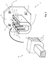
- a blackout device 1 which includes a roller shutter box 2, a winding shaft 3 and an embodiment of a drive device 4 according to the invention.
- the roller shutter curtain which is motor-driven and optionally wound onto the winding shaft 3 or unwound from the winding shaft 3, is not shown.
- the drive device 4 includes a drive motor 5, which is designed as a tubular motor and has a driven element 23 with a winding shaft coupling section 6, to which the winding shaft 2 is fastened in a rotationally fixed manner.
- the winding shaft coupling section 6 is limited axially by a stop 7 .
- the winding shaft 3 is pushed onto the entire winding shaft coupling section 6 so that it bears against the stop 7 of the driven element 23 at the front.
- the drive device 4 also has a Torque support device 8, which is coupled to the drive motor 5 and rotatably connected to a part of a building, namely with the inside of the roller shutter box 2 is connected.
- a contact surface 9 lies on the inside of the roller shutter box 2 .
- the drive device 4 also has a support shaft 10 which is connected to the drive motor 5 at one end and to the torque support device 8 at the other end. In this way, the torque generated by the drive motor 5 for driving the driven element 23 and the winding shaft 2 in rotation is supported on the roller shutter box 2 .
- the winding shaft coupling section 6 is part of the output element 23 which is driven in rotation relative to the support shaft 10 and to a drive motor housing 22 .
- the stop 7 is also part of the driven element 23.
- the blackout device 1 also has a rotary bearing 11 by means of which the winding shaft 2 is rotatably mounted at the other end of the roller shutter box 2 .
- the axial distance 12 from the winding shaft coupling section 6 to the contact surface 9 is adjustable.
- the drive device 4 can be adapted to the combination of the axial length of the winding shaft 3, the length of the roller shutter box 2 and the length of the pivot bearing 10.
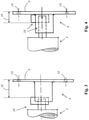
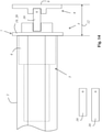
- FIGS. 2 to 4 show schematic detailed representations of a second exemplary embodiment of a drive device 4 according to the invention figure 2 only the support shaft 10, which on the one hand is non-rotatably connected to a drive motor 5 (not shown in this figure), and the torque support device 8 shown.
- the support shaft 10 can be connected in a rotationally fixed manner to the torque support device 8 in different axial relative positions.
- the torque support device 8 has a support shaft receptacle 13 into which one end of the support shaft 10 can be inserted radially in different axial positions.
- the torque support device 8 has passages 25 in a base plate 18 for fastening screws (not shown), which makes it possible to screw the torque support device 8 to a building, in particular to the inside of a roller shutter box 2 .
- the figure 2 shows that the support shaft 10 and the support shaft receptacle 13 have a plurality of axially spaced ribs 14 and a plurality of axially spaced rib receptacles 15 which interlock and secure the relative axial position of the support shaft 10 relative to the torque support device 8 when the support shaft 10 is inserted into the support shaft receptacle 13 is plugged.
- the support shaft 10 can optionally be inserted into the support shaft receptacle 8 with a shorter support shaft distance 16 from the contact surface 9, which in figure 3 is shown, or at a longer support shaft distance 16 from the contact surface 9, which is shown in figure 4 is shown.
- the support shaft distance 16 By selecting the support shaft distance 16, the axial distance 12 from the (in the Figures 2 to 4 not shown) winding shaft coupling section 7 to the contact surface 9 can be adjusted.
- the ribs 14 and the rib receptacles 15 are for the sake of clarity in the Figures 3 and 4 not shown.
- the drive motor 5 is in the Figures 3 and 4 only partially shown and indicated very schematically.
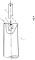
- FIGS. 5 to 8 show schematic cross-sectional representations of details of a third exemplary embodiment of a drive device 4 according to the invention, only part of the drive motor 5 with a support shaft receptacle 13 into which one end of the support shaft 10 is inserted being shown very schematically for the sake of clarity.
- the figure 5 shows details of the third exemplary embodiment of a drive device 4 according to the invention during the production of a first setting of the axial distance between the winding shaft coupling section 6 (not shown in this figure) and the contact surface 9 (not shown in this figure).
- the support shaft 10 is introduced into the support shaft receptacle 13 in a first rotational position (relative to the axial direction).
- figure 6 shows the situation after the support shaft 10 has been inserted into the support shaft receptacle 13.
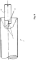
- the figure 7 shows details of the third exemplary embodiment of a drive device 4 according to the invention during the production of a second setting (different from the first setting) of the axial distance between the winding shaft coupling section 6 (not shown in this figure) and the contact surface 9 (not shown in this figure).
- second setting the support shaft 10 is introduced into the support shaft receptacle 13 with a second rotational position.
- the second rotational position differs from the first rotational position by a rotation of 180 degrees around the longitudinal central axis of the support shaft 10, which extends in the axial direction.
- figure 8 shows the situation after the support shaft 10 has been inserted into the support shaft receptacle 13. It can be seen that the maximum insertion depth in the first rotational position of the support shaft 10 ( figures 5 and 6 ) is greater than in the second rotary position of the support shaft 10 ( figures 7 and 8th ).
- the support shaft 10 can be non-rotatably connected to the drive motor 5 in different axial relative positions by the maximum insertion depth of the support shaft 10 being adjustable until an axial end stop 17 of the support shaft receptacle 13 is reached.
- the adjustability of the maximum insertion depth is achieved in that the support shaft 10 can be inserted into the support shaft receptacle 13 with one of at least two different rotational positions (to change from one rotational position to the other, a rotation around the axial direction is necessary), with the maximum insertion depth being up to to reach the end stop of the support shaft mount 13 is different for different rotational positions.
- the end stop 17 of the support shaft receptacle 13 and the end face 24 of the support shaft 12 are of stepped design.
- the support shaft 10 has, in a cross-sectional plane perpendicular to the axial direction, an outer contour that deviates from the circular shape, namely a square outer contour.
- the support shaft receptacle 13 has a complementary inner contour in a cross-sectional plane perpendicular to the axial direction, so that the support shaft 10 can be positively inserted into the support shaft receptacle 13, which enables torque transmission.
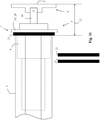
- figure 9 shows a schematic cross-sectional view of details of a fourth exemplary embodiment of a drive device 4 according to the invention during installation, in which the drive motor 5 designed as a tubular motor is pushed into a winding shaft 3, with the winding shaft coupling section 6 in particular also being pushed into the winding shaft 3.
- the winding shaft coupling section 6 is pushed completely into the winding shaft 3 until the winding shaft 3 hits a stop 7 at the front.
- the winding shaft coupling section 6 is part of an output element 23 which is driven in rotation relative to the support shaft 10 and to a drive motor housing 22 .
- a torque-transmitting connection of the winding shaft 3 to the winding shaft coupling section 6 is achieved in that the winding shaft 3 in a cross-sectional plane perpendicular to the axial direction has an inner contour that is different from the circular shape, namely an octagonal inner contour, and in that the winding shaft coupling section 6 has a shape-complementary outer contour, namely a octagonal outer contour, so that a torque-transmitting positive connection between the winding shaft coupling section 6 and the winding shaft 3 is produced when it is pushed in.
- the drive device has a torque support device 8 with a support shaft receptacle 13 into which one end of the support shaft 10 can be inserted.
- the other end of the support shaft 10 is connected to the drive motor 5 in a torque-proof manner.
- the winding shaft coupling section 6 is limited axially by the stop 7 .
- the stop 7 has a relative to the Winding shaft coupling section 6 fixed stop element 20, which is designed as a collar 19.
- the axial length of the stop 7 can be changed by adding one or more further stop elements 21, which are designed as rings. Without the addition of one of the further stop elements 21, each designed as a ring, the axial length of the stop 7 is equal to the axial length of the collar 19.
- the stop 7 becomes axially longer and the right end of the winding shaft coupling section 6 defined by the stop 7 (in relation to the figures) is shifted to the left.
- the axial distance from the winding shaft coupling section 6 to the contact surface 9 is adjustable in this embodiment by adjusting the axial length of the stop 7, which is the Figures 10 to 12 which show the drive device 4 in the installed state, illustrate.
- figure 10 shows the use of the drive device 4 without an additional stop element 21.
- figure 9 shows the use of the drive device 4 using a single additional stop element 21.
- figure 10 shows the use of the drive device 4 using two additional stop elements 21.
- the Figures 10 to 12 show: The more stop elements 21 are used, the greater the axial distance 12 between the winding shaft coupling section 6 and the contact surface 9.
- figure 13 shows a schematic cross-sectional representation of details of a fifth exemplary embodiment of a drive device according to the invention during assembly.
- the drive device has three different lengths, each on the one hand supporting shafts (10) which can be connected to the drive motor (5) and, on the other hand, to the torque support device (8).
- the user can select one of the support shafts (10) and plug it into a first support shaft receptacle (13) of the drive motor and on the other hand into a second support shaft receptacle (13) of the torque support device (8).
- the axial distance 12 between the winding shaft coupling section 6 and the contact surface 9 can be defined. The longer the selected support shaft (10), the greater the axial distance 12 between the winding shaft coupling section 6 and the contact surface 9, which is in the Figures 14 to 16 is illustrated.
Landscapes
- Engineering & Computer Science (AREA)
- Structural Engineering (AREA)
- Architecture (AREA)
- Civil Engineering (AREA)
- Operating, Guiding And Securing Of Roll- Type Closing Members (AREA)
- Winding Of Webs (AREA)
- Manufacture Of Motors, Generators (AREA)
Applications Claiming Priority (1)
| Application Number | Priority Date | Filing Date | Title |
|---|---|---|---|
| LU102002A LU102002B1 (de) | 2020-08-24 | 2020-08-24 | Antriebsvorrichtung für eine Wickelwelle einer Verdunklungsvorrichtung |
Publications (2)
| Publication Number | Publication Date |
|---|---|
| EP3960979A2 true EP3960979A2 (fr) | 2022-03-02 |
| EP3960979A3 EP3960979A3 (fr) | 2022-05-18 |
Family
ID=72896033
Family Applications (1)
| Application Number | Title | Priority Date | Filing Date |
|---|---|---|---|
| EP21192073.1A Withdrawn EP3960979A3 (fr) | 2020-08-24 | 2021-08-19 | Dispositif d'entraînement pour un arbre d'enroulement d'un dispositif d'obscurcissement |
Country Status (2)
| Country | Link |
|---|---|
| EP (1) | EP3960979A3 (fr) |
| LU (1) | LU102002B1 (fr) |
Citations (3)
| Publication number | Priority date | Publication date | Assignee | Title |
|---|---|---|---|---|
| DE102012200037A1 (de) | 2012-01-03 | 2013-07-04 | Alfred Schellenberg Gmbh | Antriebsvorrichtung zum Auf- und Abwickeln einer Verdunkelungsvorrichtung, insbesondere eines Rollladens o.dgl. |
| DE202015008731U1 (de) | 2015-12-19 | 2016-01-22 | Alukon Kg | Motorlager |
| US20160376842A1 (en) | 2015-06-24 | 2016-12-29 | Somfy Sas | Winding device for a windable screen and closure or sun-protection home-automation installation including such a device |
Family Cites Families (1)
| Publication number | Priority date | Publication date | Assignee | Title |
|---|---|---|---|---|
| FR3055652B1 (fr) * | 2016-09-08 | 2018-08-31 | Bubendorff | Dispositif d'enroulement/deroulement d'un ecran par exemple du type volet roulant. |
-
2020
- 2020-08-24 LU LU102002A patent/LU102002B1/de active IP Right Grant
-
2021
- 2021-08-19 EP EP21192073.1A patent/EP3960979A3/fr not_active Withdrawn
Patent Citations (3)
| Publication number | Priority date | Publication date | Assignee | Title |
|---|---|---|---|---|
| DE102012200037A1 (de) | 2012-01-03 | 2013-07-04 | Alfred Schellenberg Gmbh | Antriebsvorrichtung zum Auf- und Abwickeln einer Verdunkelungsvorrichtung, insbesondere eines Rollladens o.dgl. |
| US20160376842A1 (en) | 2015-06-24 | 2016-12-29 | Somfy Sas | Winding device for a windable screen and closure or sun-protection home-automation installation including such a device |
| DE202015008731U1 (de) | 2015-12-19 | 2016-01-22 | Alukon Kg | Motorlager |
Also Published As
| Publication number | Publication date |
|---|---|
| EP3960979A3 (fr) | 2022-05-18 |
| LU102002B1 (de) | 2022-02-24 |
Similar Documents
| Publication | Publication Date | Title |
|---|---|---|
| EP3388610B1 (fr) | Assemblage d'arbre, dispositif de fermeture ou de protection ainsi que jeu de montage | |
| EP3997363B1 (fr) | Entraînement de commande comprenant un dispositif de limitation de couple | |
| DE102010063953A1 (de) | Handwerkzeugmaschine | |
| DE2913887A1 (de) | Lamellenjalousie mit vertikalen lamellen | |
| WO2018007439A1 (fr) | Unité de transmission, motoréducteur électrique et siège | |
| EP2385210B1 (fr) | Engrenage planétaire pour moteurs d'entraînement | |
| DE3504489A1 (de) | Vorrichtung zur handbetaetigung der elektromotorisch antreibbaren wickelwelle z.b. eines rolladens bei stromlosem elektromotor | |
| DE69602476T2 (de) | Vorrichtung zur Befestigung einer Rolladenwelle | |
| EP2464806B1 (fr) | Mécanisme de transmission | |
| DE2426719A1 (de) | Vorrichtung zum verstellen der abschaltpunkte eines elektromotorischen jalousieantriebes | |
| EP3960979A2 (fr) | Dispositif d'entraînement pour un arbre d'enroulement d'un dispositif d'obscurcissement | |
| EP2354426B1 (fr) | Assemblage d'une paroi frontale de coffre de store et d'une plaque de montage | |
| EP2520754B1 (fr) | Dispositif d'entraînement pour la sangle d'un volet roulant comprenant une transmission à plusieurs rapports | |
| DE3608988A1 (de) | Vorrichtung zur handbetaetigung einer elektromotorisch antreibbaren wickelwelle z.b. eines rolladens | |
| EP2565364A2 (fr) | Adaptateur pour l'arbre entraîné d'un dispositif d'entraînement tubulaire pour enrouler et dérouler un dispositif d'assombrissement, en particulier un store ou analogue | |
| EP0268149B1 (fr) | Engrenage pour enrouler et dérouler un volet roulant se composant de plusieurs lamelles ainsi que paroi d'enveloppe pour cela | |
| DE102016215571B4 (de) | Sitz mit einer Befestigungsanordnung eines Elektromotors | |
| LU101351B1 (de) | Rohrmotorset | |
| DE202016106903U1 (de) | Modulares Stecksystem | |
| DE102018009935B4 (de) | Antriebsvorrichtung für eine Gebäudeöffnungsverschattung | |
| DE2739151A1 (de) | Endschaltervorrichtung, insbesondere fuer rolladen und jalousien | |
| EP3757416A1 (fr) | Agencement de transmission commutable | |
| EP3916192B1 (fr) | Mécanisme à manivelle pour rideaux à commande électrique | |
| EP2918769B1 (fr) | Ensemble essieu coulissant et verrouillable d'un arbre d'enroulement du dispositif d'ombrage | |
| DE102013107990A1 (de) | Hebewinde für Rolläden, Jalousien und dgl. |
Legal Events
| Date | Code | Title | Description |
|---|---|---|---|
| PUAI | Public reference made under article 153(3) epc to a published international application that has entered the european phase |
Free format text: ORIGINAL CODE: 0009012 |
|
| STAA | Information on the status of an ep patent application or granted ep patent |
Free format text: STATUS: THE APPLICATION HAS BEEN PUBLISHED |
|
| AK | Designated contracting states |
Kind code of ref document: A2 Designated state(s): AL AT BE BG CH CY CZ DE DK EE ES FI FR GB GR HR HU IE IS IT LI LT LU LV MC MK MT NL NO PL PT RO RS SE SI SK SM TR |
|
| PUAL | Search report despatched |
Free format text: ORIGINAL CODE: 0009013 |
|
| AK | Designated contracting states |
Kind code of ref document: A3 Designated state(s): AL AT BE BG CH CY CZ DE DK EE ES FI FR GB GR HR HU IE IS IT LI LT LU LV MC MK MT NL NO PL PT RO RS SE SI SK SM TR |
|
| RIC1 | Information provided on ipc code assigned before grant |
Ipc: E06B 9/72 20060101ALI20220413BHEP Ipc: E06B 9/174 20060101AFI20220413BHEP |
|
| STAA | Information on the status of an ep patent application or granted ep patent |
Free format text: STATUS: REQUEST FOR EXAMINATION WAS MADE |
|
| 17P | Request for examination filed |
Effective date: 20221117 |
|
| RBV | Designated contracting states (corrected) |
Designated state(s): AL AT BE BG CH CY CZ DE DK EE ES FI FR GB GR HR HU IE IS IT LI LT LU LV MC MK MT NL NO PL PT RO RS SE SI SK SM TR |
|
| GRAP | Despatch of communication of intention to grant a patent |
Free format text: ORIGINAL CODE: EPIDOSNIGR1 |
|
| STAA | Information on the status of an ep patent application or granted ep patent |
Free format text: STATUS: GRANT OF PATENT IS INTENDED |
|
| RIC1 | Information provided on ipc code assigned before grant |
Ipc: E06B 9/72 20060101ALI20231031BHEP Ipc: E06B 9/174 20060101AFI20231031BHEP |
|
| INTG | Intention to grant announced |
Effective date: 20231121 |
|
| STAA | Information on the status of an ep patent application or granted ep patent |
Free format text: STATUS: THE APPLICATION IS DEEMED TO BE WITHDRAWN |
|
| 18D | Application deemed to be withdrawn |
Effective date: 20240322 |