EP3961027A1 - Propulsion éolienne à turbines multiples pour utiliser le vent de vitesse des véhicules automobiles - Google Patents
Propulsion éolienne à turbines multiples pour utiliser le vent de vitesse des véhicules automobiles Download PDFInfo
- Publication number
- EP3961027A1 EP3961027A1 EP20192530.2A EP20192530A EP3961027A1 EP 3961027 A1 EP3961027 A1 EP 3961027A1 EP 20192530 A EP20192530 A EP 20192530A EP 3961027 A1 EP3961027 A1 EP 3961027A1
- Authority
- EP
- European Patent Office
- Prior art keywords
- der
- die
- wind
- metuwak
- cassette
- Prior art date
- Legal status (The legal status is an assumption and is not a legal conclusion. Google has not performed a legal analysis and makes no representation as to the accuracy of the status listed.)
- Granted
Links
Images





Classifications
-
- F—MECHANICAL ENGINEERING; LIGHTING; HEATING; WEAPONS; BLASTING
- F03—MACHINES OR ENGINES FOR LIQUIDS; WIND, SPRING, OR WEIGHT MOTORS; PRODUCING MECHANICAL POWER OR A REACTIVE PROPULSIVE THRUST, NOT OTHERWISE PROVIDED FOR
- F03D—WIND MOTORS
- F03D3/00—Wind motors with rotation axis substantially perpendicular to the air flow entering the rotor
- F03D3/02—Wind motors with rotation axis substantially perpendicular to the air flow entering the rotor having a plurality of rotors
-
- F—MECHANICAL ENGINEERING; LIGHTING; HEATING; WEAPONS; BLASTING
- F03—MACHINES OR ENGINES FOR LIQUIDS; WIND, SPRING, OR WEIGHT MOTORS; PRODUCING MECHANICAL POWER OR A REACTIVE PROPULSIVE THRUST, NOT OTHERWISE PROVIDED FOR
- F03D—WIND MOTORS
- F03D15/00—Transmission of mechanical power
- F03D15/10—Transmission of mechanical power using gearing not limited to rotary motion, e.g. with oscillating or reciprocating members
-
- F—MECHANICAL ENGINEERING; LIGHTING; HEATING; WEAPONS; BLASTING
- F03—MACHINES OR ENGINES FOR LIQUIDS; WIND, SPRING, OR WEIGHT MOTORS; PRODUCING MECHANICAL POWER OR A REACTIVE PROPULSIVE THRUST, NOT OTHERWISE PROVIDED FOR
- F03D—WIND MOTORS
- F03D9/00—Adaptations of wind motors for special use; Combinations of wind motors with apparatus driven thereby; Wind motors specially adapted for installation in particular locations
- F03D9/30—Wind motors specially adapted for installation in particular locations
- F03D9/34—Wind motors specially adapted for installation in particular locations on stationary objects or on stationary man-made structures
- F03D9/43—Wind motors specially adapted for installation in particular locations on stationary objects or on stationary man-made structures using infrastructure primarily used for other purposes, e.g. masts for overhead railway power lines
- F03D9/46—Tunnels or streets
-
- F—MECHANICAL ENGINEERING; LIGHTING; HEATING; WEAPONS; BLASTING
- F05—INDEXING SCHEMES RELATING TO ENGINES OR PUMPS IN VARIOUS SUBCLASSES OF CLASSES F01-F04
- F05B—INDEXING SCHEME RELATING TO WIND, SPRING, WEIGHT, INERTIA OR LIKE MOTORS, TO MACHINES OR ENGINES FOR LIQUIDS COVERED BY SUBCLASSES F03B, F03D AND F03G
- F05B2240/00—Components
- F05B2240/90—Mounting on supporting structures or systems
- F05B2240/91—Mounting on supporting structures or systems on a stationary structure
- F05B2240/911—Mounting on supporting structures or systems on a stationary structure already existing for a prior purpose
- F05B2240/9113—Mounting on supporting structures or systems on a stationary structure already existing for a prior purpose which is a roadway, rail track, or the like for recovering energy from moving vehicles
-
- Y—GENERAL TAGGING OF NEW TECHNOLOGICAL DEVELOPMENTS; GENERAL TAGGING OF CROSS-SECTIONAL TECHNOLOGIES SPANNING OVER SEVERAL SECTIONS OF THE IPC; TECHNICAL SUBJECTS COVERED BY FORMER USPC CROSS-REFERENCE ART COLLECTIONS [XRACs] AND DIGESTS
- Y02—TECHNOLOGIES OR APPLICATIONS FOR MITIGATION OR ADAPTATION AGAINST CLIMATE CHANGE
- Y02B—CLIMATE CHANGE MITIGATION TECHNOLOGIES RELATED TO BUILDINGS, e.g. HOUSING, HOUSE APPLIANCES OR RELATED END-USER APPLICATIONS
- Y02B10/00—Integration of renewable energy sources in buildings
- Y02B10/30—Wind power
-
- Y—GENERAL TAGGING OF NEW TECHNOLOGICAL DEVELOPMENTS; GENERAL TAGGING OF CROSS-SECTIONAL TECHNOLOGIES SPANNING OVER SEVERAL SECTIONS OF THE IPC; TECHNICAL SUBJECTS COVERED BY FORMER USPC CROSS-REFERENCE ART COLLECTIONS [XRACs] AND DIGESTS
- Y02—TECHNOLOGIES OR APPLICATIONS FOR MITIGATION OR ADAPTATION AGAINST CLIMATE CHANGE
- Y02E—REDUCTION OF GREENHOUSE GAS [GHG] EMISSIONS, RELATED TO ENERGY GENERATION, TRANSMISSION OR DISTRIBUTION
- Y02E10/00—Energy generation through renewable energy sources
- Y02E10/70—Wind energy
- Y02E10/728—Onshore wind turbines
Definitions
- the invention relates to a wind power plant for using the relative wind of motor vehicles.
- a wind turbine which is arranged in the area of the median between two lanes to be driven in opposite directions and is thus positioned in such a way that the winds triggered by passing vehicles can be absorbed, derived and converted into energy.
- the wind rotors with a vertical axis of rotation which are set up individually at relatively large distances of at least 10 m from one another to avoid mutual interference, lead to a low energy yield.
- the object of the invention is to specify a wind power plant for using the relative wind of motor vehicles, which can be operated reliably and safely with a simple and inexpensive construction and which enables a high energy yield.
- a wind power plant for using the airflow from motor vehicles is provided with a plurality of wind turbines, each with a vertical axis of rotation, which are arranged in a row one behind the other in a support structure, the wind turbines driving a common output shaft via a rotation transmission mechanism.
- Position and directional information such as "up” or “down” used for simplification refer to the usual assembly arrangement shown in the figures. Dimensions indicated in the figures and used in the description serve only to illustrate typical, advantageous dimensions. The different variants can be used in any meaningful way be combined with each other. For example, the design with integrated street lamps is also in the embodiment according to FIG. 5 possible, even if this is not expressly mentioned in the text.
- the multi-turbine wind propulsion plant Kolesnikov according to the invention is hereinafter referred to as METUWAK.
- the system consists, among other things, of the hard triangular or quadrangular support structure (referred to below as the cassette) with a preferred length of 6000 mm, which is installed on or in the concrete crash barrier of the central separation of a motorway, federal highway, etc.
- the cassette hard triangular or quadrangular support structure
- some (depending on the size) standing wind turbines are installed in the warehouses, which can rotate counterclockwise (or clockwise for left-hand traffic) around the vertical axis of rotation. These wind turbines are turned up or driven by the air currents of the passing cars.
- the geometric dimensions of the cassette are selected according to the requirements for efficient transport to the installation site and according to the width of the concrete (or metal) baffles of the lane dividing strip.
- the width of the cassette (external dimension) is preferably a multiple (meaning here a divider) of the width of the standard truck body (2400 mm) and is 600 mm, 800 mm or 1200 mm. In this way, 4, 3 or 2 cassettes can be placed side by side.
- the length of the cassette is a multiple of the standard length of the profile tube and is 3000 mm or 6000 mm.
- the height of the cassette is selected as a multiple (meaning a divider) of 6000mm, thereby minimizing metal waste and scrap.
- the cassettes of the METUWAK are sequentially installed piece by piece on (or in) the crash barriers of the lanes and together with the connecting cable or tied with the composite and control cable.
- the cassettes form segments of different lengths.
- Rotating wind turbines transmit through a rotation transmission mechanism (hereinafter referred to as RTM), the total (sum) torque of all (preferably 5 to 30 pieces) wind turbines to the torque receiver.
- RTM rotation transmission mechanism
- the RÜM consists of two compensating beams that are connected to the turbines and the axis of the receiver via hinges.
- the mechanism for absorbing rotary motion produces "power" (as a physical quantity).
- the generator produces electricity immediately.
- a compressor or air cylinder produces compressed air for further storage and use in various devices (e.g. air motors).
- Power as a METUWAK product (or as a physical unit) can be used to lift water up and store it in tanks to then divert it into the blades of hydraulic turbines and generate electricity (principle of a pumped storage power plant).
- the flywheel stores kinetic energy that can be quickly converted into electrical energy by a generator. With the flywheels, voltage peaks in the network can be compensated.
- METUWAK consists of:
- the cassette is designed to allow elements to be installed and fixed on it and inside.
- the cassette is preferably made of rectangular cross-section metal pipes, which are sufficient for the stable maintenance and durability of the device during assembly/dismantling and for the stable operation of the device in strong winds.
- cassettes and turbines are painted with the anti-rust light-absorbing substances to eliminate light spots that disturb the drivers.
- the cassette has a central crossbeam (or central longitudinal beam) in which the components of the bearing suspension of the stationary turbines are mounted, which ensure the free rotation of the turbines counterclockwise. If necessary, the steel structure of the individual generators is mounted on the central crossbeam.
- the side surface of the cassette is covered with a metal or mesh plastic covering that protects the road against turbine fragments in the event of mechanical damage or defective manufacture.
- the "operation" as a METUWAK product can be used to lift water up and store it in tanks for subsequent discharge into the blades of hydraulic turbines to generate electricity.
- the flywheel stores kinetic energy that can be quickly converted into electrical energy by a generator.
- the flywheels make it possible to compensate for overvoltages in the mains voltage.
- the cassette of the METUWAK is the main structural element of the METUWAK. All other components are hard attached to them. Standing turbines are attached to the central (upper and lower) crossbeams of the cassette by the structural members of the bearing suspension.
- an RÜM is installed in the process room in addition to the generator itself.
- the latter are rigidly connected to the cassette on the lower (technological) level of the cassette, hereinafter called the technological section, which is a rectangular niche that also houses other elements of the facility METUWAK are installed: a control and measuring device unit (hereinafter referred to as KuME), and the battery, as well as laid control and connection cables.
- KuME control and measuring device unit
- the mounting brackets are first "put on the whipstock" and then, after the cassette is set at horizon level, firmly attached to the cassette.
- the weights of the supports are first installed on the ground, then the supports themselves are inserted into the baffles, and the cassette itself is installed on the baffles with a crane, and after aligning the cassette with the horizon, rigidly attached attached to the supports.
- the cassette is then connected to the previous and next segment cassette via connection and control cables.
- the system for attaching the lights or spotlights to the cassette is designed and built in the factory in such a way that the Installation angles relative to the roadway cannot be changed by personnel during installation.
- the structural elements are also electrically connected.
- the generators (and the motorcycles) are powered by the battery to achieve operating speeds (optional) and the electricity produced is transmitted via cables to either the load or the battery.
- the cassette of the METUWAK stands firmly on the adjustable fixing systems and is connected to the neighboring segments of the cassette by cables.
- the air currents from the passing cars hit the turbine blades. This creates the rotational movement around the stationary turbine axis.
- the turbine axles are hard coupled to the own generator and are rotated by the runner.
- the turbine turning is handed off through the RTM to the turbine runner of the whole cassette generator.
- the generators produce the electric current, which flows either through the KuME to the KAB, or through the connection cable to the users or consumers.
- the KuME controls the preliminary turning of the turbines (optional), battery charging, switching on and off of the lighting devices, transferring the energy contained in the generators through the cables to the users or consumers.
- the KuME gets electricity from all generators of the cassette, "mixes” them, adjusts them by span and rate and other parameters. Next will the constant current (or alternating current) passed to the users.
- the Ku-ME collects the information about the working parameters of the cassette and transfers it through the control cables or WiFi to the external system control panel, which processes all the information from all the cassettes in the segment and, if necessary, gives the task for the intensive work of the generators.
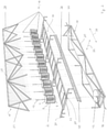
- FIG. 1 shows an exemplary realization of a multi-turbine wind propulsion (power plant) system according to Kolesnikov, called METUWAK, in a perspective view and FIG. 2 an associated exploded view.
- FIG. 3 shows corresponding views and sections
- the METUWAK is designed to convert the airflow from passing motor vehicles (or trains) into usable electrical energy or mechanical work and comprises a segment with a plurality (12 in this example) of similar, upright wind rotors or wind turbines 2, each with a vertical axis of rotation (vertical rotor ) arranged in a row one after the other.
- the distances between the wind turbines 2 are relatively small, in particular smaller than the respective turbine diameter.
- Each of the wind turbines 2 comprises a circular upper end plate or cap 4 and a corresponding lower cover disk 6 of the same diameter, between which the vertically aligned turbine blades 8 or rotor blades are arranged.
- the rotor shape described is known as the Savonius rotor. Instead, a shell rotor, a flow-through rotor, a Darrieus rotor or a hybrid form could also be used. All rotors within a segment are preferably of the same or at least of a similar type with similar dimensions, so that the greatest possible compatibility of the running and response behavior for the intended mechanical coupling (see below) is provided.
- the part of the respective turbine shaft 12 which protrudes upwards and downwards is held in bearings 14, 16 which are attached to the support frame 10 or are integrated into it.
- the support structure 10 comprises a lower part 20 that is U-shaped in terms of its outer contour in cross section, a lattice-like, flat and horizontally aligned central part 22, and an upper part 24 that is triangular in cross section and tapers upwards with an upper longitudinal beam 28 extending in the longitudinal direction 26
- the upper bearings 14 for the turbine shaft 12 are located in or on the longitudinal beam 28.
- the lower bearings 16 are located in or on the cross beam 30 of the central part 22.
- the support frame 10 itself or the unit made up of the support frame 10 and wind turbines 2 and, if necessary, other built-in components is also referred to as a cassette or segment.
- the supports 34 are equipped with adjustable fixings 36 for permanent and loadable attachment to the central barrier or lane separation.
- the sloping side walls of the upper part 24 shaped as a triangular prism are covered with fishing nets or short nets 38 made of metal or plastic, there being a sufficiently large distance between the nets 38 and the wind turbines 2 so as not to impede the rotation of the wind turbines 2 .
- the nets 38 are used to catch and hold back fragments in the event of a wind turbine 2 breaking. Nets can also be stretched across the two triangular end faces of the segment.
- the mesh size of the nets 38 is selected in such a way that, on the one hand, fragments that are dangerous for road traffic are held back and, on the other hand, the flow of wind through them is only impeded to an insignificant extent.
- the wind turbines 2 of the segment through a coupling referred to as a rotary transfer mechanism 40 (RTM), drive a common output shaft 42, which in turn drives an electrical generator, flywheel, or work machine such as a compressor.
- the output shaft 42 and the rotation transmission mechanism 40 are preferably arranged in the lower part of the support structure 10 .
- the generator, the flywheel or the working machine can also be arranged there, specifically as low as possible, or alternatively outside of the support structure 10.
- a control and measuring device unit 44 (KuME) and/or possibly further electrical components can also be arranged there, such as accumulators. Electrical connection and/or control lines 46 can be routed out of the lower part 20 at the side or below.
- Connecting rods or cranks 48 are eccentrically articulated on the lower end plates 6 of the wind turbines 2 and transmit the rotational movement of all wind turbines 2 to a common push rod 50 running in the longitudinal direction 26, which thereby executes an oscillating pushing movement (sliding crank principle).
- An oscillating movement in the transverse direction 32 is superimposed on the oscillating movement in the longitudinal direction 26, so that overall any fixed point of the push rod 50 moves on an elliptical path in a horizontal plane.
- the push rod 50 can be connected directly to the connecting rod or a crank Output shaft 42 may be connected, so that the rotational movement of all wind turbines 2 is coupled and transmitted via the crank mechanism to the output shaft 42 slider crank mechanism as a variant of a coupling mechanism.
- the first push rod 50 acted upon by the wind turbines 2 is coupled via several connecting rods or cranks 52 to a second push rod 54 lying below it, which in turn acts on the output shaft 42 via a crank 56 .
- the second push rod 54 also moves in an elliptically oscillating manner in a horizontal plane, out of phase with the movement of the first push rod 50.
- the RÜM 40 ensures that the torques of the individual wind turbines 2 add up to the output shaft 42, as a result of which a correspondingly powerful generator can be driven, for example.
- cranks 48 and/or 56 can possibly be dispensed with if the connecting rods 50 and/or 54 are mounted directly eccentrically on the rotating turbine or shaft parts.
- FIG. 4 emerges, in which the movement is broken down into four snapshots arranged side by side.
- one or more or all of the wind turbines 2 can be connected via their turbine shaft 12 to a generator that is assigned exclusively to them and is rather small and low-power in comparison to the cassette generator described.
- the electrical energy generated and stored in the accumulator when the wind is strong enough can be used to operate the generator as an electric motor or alternatively a separate auxiliary motor when the wind is weak, and in this way the rotation to start the wind turbines 2 beyond the initial frictional resistance (start-up aid). As soon as this resistance has been overcome, it can be switched back to generator operation.
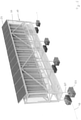
- FIG. 5 in perspective view and in FIG. 6
- the variant of the METUWAK shown in three associated side views differs from the previously described one in that the upper part 24 of the support frame 10 or the cassette is box-shaped with a rectangular cross-section.
- the wind turbines 2 (here in the example 16 pieces) are arranged inside the box, with the two side walls and possibly the end faces being secured again with nets 38 .
- a cover panel may be placed on top of the box to protect the underlying components.
- a cover by solar panels 58 is provided for additional energy generation when the sun is shining.
- this variant provides for an elevated installation on the ground of the roadway or the median.
- the lower part 20 of the support structure 10 is equipped with suitable supports 60, which are preferably anchored to the ground.
- Ballast body 62 for example on the supports 60 or on/in the lower part 20, can be provided so that their own weight supports a more secure and immovable installation of the cassette.
- heavy accumulators can serve as ballast.
- the cassette could also be attached to an existing concrete partition or the like between the lanes.
- FIG. 7 shows a concrete application situation with several METUWAK segments installed one after the other on concrete slabs of a lane separation of a motorway. Also shown are optional street lights that can be attached to the scaffolding to illuminate the roadway. Lamps of this type are supplied with electricity directly by METUWAK.
- FIG. 8th shows a corresponding application along railroad tracks.
- the straight segments are kept shorter in order to be able to follow the course of the curve.
Landscapes
- Engineering & Computer Science (AREA)
- Life Sciences & Earth Sciences (AREA)
- Sustainable Development (AREA)
- Sustainable Energy (AREA)
- Chemical & Material Sciences (AREA)
- Combustion & Propulsion (AREA)
- Mechanical Engineering (AREA)
- General Engineering & Computer Science (AREA)
- Power Engineering (AREA)
- Wind Motors (AREA)
- Structures Of Non-Positive Displacement Pumps (AREA)
Priority Applications (2)
| Application Number | Priority Date | Filing Date | Title |
|---|---|---|---|
| ES20192530T ES2935735T3 (es) | 2020-08-25 | 2020-08-25 | Accionamiento eólico multiturbina para utilizar el viento de velocidad de vehículos de motor |
| EP20192530.2A EP3961027B1 (fr) | 2020-08-25 | 2020-08-25 | Propulsion éolienne à turbines multiples pour utiliser le vent de vitesse des véhicules automobiles |
Applications Claiming Priority (1)
| Application Number | Priority Date | Filing Date | Title |
|---|---|---|---|
| EP20192530.2A EP3961027B1 (fr) | 2020-08-25 | 2020-08-25 | Propulsion éolienne à turbines multiples pour utiliser le vent de vitesse des véhicules automobiles |
Publications (2)
| Publication Number | Publication Date |
|---|---|
| EP3961027A1 true EP3961027A1 (fr) | 2022-03-02 |
| EP3961027B1 EP3961027B1 (fr) | 2022-10-12 |
Family
ID=72240299
Family Applications (1)
| Application Number | Title | Priority Date | Filing Date |
|---|---|---|---|
| EP20192530.2A Active EP3961027B1 (fr) | 2020-08-25 | 2020-08-25 | Propulsion éolienne à turbines multiples pour utiliser le vent de vitesse des véhicules automobiles |
Country Status (2)
| Country | Link |
|---|---|
| EP (1) | EP3961027B1 (fr) |
| ES (1) | ES2935735T3 (fr) |
Cited By (1)
| Publication number | Priority date | Publication date | Assignee | Title |
|---|---|---|---|---|
| WO2024177726A1 (fr) * | 2023-02-23 | 2024-08-29 | Airiva Renewables, Inc. | Réseau linéaire de réseaux de pales d'éolienne |
Citations (4)
| Publication number | Priority date | Publication date | Assignee | Title |
|---|---|---|---|---|
| US5272378A (en) * | 1992-08-06 | 1993-12-21 | Wither Thomas A | Apparatus for generating power |
| DE10330601A1 (de) | 2003-07-08 | 2005-02-03 | Ernst, Jürgen | Windkraftanlage |
| US20090224552A1 (en) * | 2007-06-22 | 2009-09-10 | Sulentic Joseph N | Multiple Turbine Energy Collector and System |
| EP3070328A1 (fr) * | 2013-11-11 | 2016-09-21 | Sang Whan Lee | Dispositif de collecte d'énergie éolienne et de production d'électricité |
-
2020
- 2020-08-25 ES ES20192530T patent/ES2935735T3/es active Active
- 2020-08-25 EP EP20192530.2A patent/EP3961027B1/fr active Active
Patent Citations (4)
| Publication number | Priority date | Publication date | Assignee | Title |
|---|---|---|---|---|
| US5272378A (en) * | 1992-08-06 | 1993-12-21 | Wither Thomas A | Apparatus for generating power |
| DE10330601A1 (de) | 2003-07-08 | 2005-02-03 | Ernst, Jürgen | Windkraftanlage |
| US20090224552A1 (en) * | 2007-06-22 | 2009-09-10 | Sulentic Joseph N | Multiple Turbine Energy Collector and System |
| EP3070328A1 (fr) * | 2013-11-11 | 2016-09-21 | Sang Whan Lee | Dispositif de collecte d'énergie éolienne et de production d'électricité |
Cited By (2)
| Publication number | Priority date | Publication date | Assignee | Title |
|---|---|---|---|---|
| WO2024177726A1 (fr) * | 2023-02-23 | 2024-08-29 | Airiva Renewables, Inc. | Réseau linéaire de réseaux de pales d'éolienne |
| US12180933B2 (en) | 2023-02-23 | 2024-12-31 | Airiva Renewables, Inc. | Linear network of wind turbine blade arrays having hub frame and blade formation with segments |
Also Published As
| Publication number | Publication date |
|---|---|
| ES2935735T3 (es) | 2023-03-09 |
| EP3961027B1 (fr) | 2022-10-12 |
Similar Documents
| Publication | Publication Date | Title |
|---|---|---|
| EP2926063B1 (fr) | Dispositif d'asservissement équipé d'une structure de réception déplaçable sur un ou plusieurs axes et destinée au montage d'un ou plusieurs éléments sensibles aux ondes électromagnétiques et présentant une direction de rayonnement préférentielle | |
| EP2532989B1 (fr) | Installation dotée d'une structure de support réglable sur un axe autour d'un axe horizontal pour la réception d'un ou plusieurs panneaux solaires ou modules photovoltaïques ou analogues | |
| WO2008084102A2 (fr) | Dispositif composé d'une pluralité de modules structurels et dispositif de guidage de modules pour la conversion ou la concentration de l'énergie solaire | |
| DE102012021697B4 (de) | Tragsystem für die Stabilisierung von mindestens einem Mast | |
| DE3407881A1 (de) | Energieversorgungssystem | |
| DE4431154C2 (de) | Verbund- Energiekonverter zur Nutzung von Solarenergie | |
| DE20321844U1 (de) | Vorrichtung zum Erzeugen von Strom aus Windkraft | |
| DE102018110833A1 (de) | Ladestation für Elektrofahrzeuge mit einem Dach umfassend Solarmodule | |
| EP3961027B1 (fr) | Propulsion éolienne à turbines multiples pour utiliser le vent de vitesse des véhicules automobiles | |
| DE69707418T2 (de) | Solarkollektor mit pyramidenförmiger drehbarer vorrichtung | |
| WO1998009072A9 (fr) | Pylones pour eolienne | |
| DE202012012303U1 (de) | "Windkraftanlage für LKW und Nutzfahrzeuge" (nachstehend"Mobile Windkraftanlage" genannt) | |
| DE69510322T2 (de) | Erzeugung von elektrischer energie durch wind angetriebene vorrichtung | |
| DE202011107155U1 (de) | Vorrichtung zur Energiewandlung | |
| DE102018110831A1 (de) | Ladestation für Elektrofahrzeuge mit einem Fundamentabschnitt und einem Funktionsabschnittt | |
| EP3800346A1 (fr) | Installation photovoltaïque pour éoliennes en tant que système de génération de courant et également en tant qu'une installation autonome sans éolienne ainsi que son procédé de fonctionnement | |
| DE202011105918U1 (de) | Vorrichtung zur Drehung einer Trägerstruktur um eine Hauptachse für den Einsatz in einer mit planaren Elementen oder Flächen ausgestatteten Anlage, insbesondere einer Solaranlage | |
| DE19615795A1 (de) | Windkraftanlage zur Erzeugung elektrischer Energie | |
| EP0802324A1 (fr) | Eolienne | |
| EP1035325B1 (fr) | Eolienne transportable | |
| EP3617406B1 (fr) | Système modulaire de pontage | |
| DE102022001975A1 (de) | E-Ladeeinrichtung für stationäre und mobile Stromquellen | |
| EP4080044B1 (fr) | Unité de conversion d'énergie, agencement de conversion d'énergie, système de conversion d'énergie et réseau | |
| DE10056325C2 (de) | Vorrichtung zur Ausleuchtung von Crashtest-Anlagen | |
| DE9217792U1 (de) | Straßenbauwerk mit Solarenergieeinrichtung |
Legal Events
| Date | Code | Title | Description |
|---|---|---|---|
| STAA | Information on the status of an ep patent application or granted ep patent |
Free format text: STATUS: EXAMINATION IS IN PROGRESS |
|
| PUAI | Public reference made under article 153(3) epc to a published international application that has entered the european phase |
Free format text: ORIGINAL CODE: 0009012 |
|
| 17P | Request for examination filed |
Effective date: 20210514 |
|
| AK | Designated contracting states |
Kind code of ref document: A1 Designated state(s): AL AT BE BG CH CY CZ DE DK EE ES FI FR GB GR HR HU IE IS IT LI LT LU LV MC MK MT NL NO PL PT RO RS SE SI SK SM TR |
|
| GRAP | Despatch of communication of intention to grant a patent |
Free format text: ORIGINAL CODE: EPIDOSNIGR1 |
|
| STAA | Information on the status of an ep patent application or granted ep patent |
Free format text: STATUS: GRANT OF PATENT IS INTENDED |
|
| INTG | Intention to grant announced |
Effective date: 20220401 |
|
| GRAS | Grant fee paid |
Free format text: ORIGINAL CODE: EPIDOSNIGR3 |
|
| RAP1 | Party data changed (applicant data changed or rights of an application transferred) |
Owner name: AWINGEN GMBH |
|
| RIN1 | Information on inventor provided before grant (corrected) |
Inventor name: KOLESNIKOV, ANTON |
|
| GRAA | (expected) grant |
Free format text: ORIGINAL CODE: 0009210 |
|
| STAA | Information on the status of an ep patent application or granted ep patent |
Free format text: STATUS: THE PATENT HAS BEEN GRANTED |
|
| AK | Designated contracting states |
Kind code of ref document: B1 Designated state(s): AL AT BE BG CH CY CZ DE DK EE ES FI FR GB GR HR HU IE IS IT LI LT LU LV MC MK MT NL NO PL PT RO RS SE SI SK SM TR |
|
| REG | Reference to a national code |
Ref country code: GB Ref legal event code: FG4D Free format text: NOT ENGLISH |
|
| REG | Reference to a national code |
Ref country code: CH Ref legal event code: EP |
|
| REG | Reference to a national code |
Ref country code: DE Ref legal event code: R096 Ref document number: 502020001834 Country of ref document: DE |
|
| REG | Reference to a national code |
Ref country code: IE Ref legal event code: FG4D Free format text: LANGUAGE OF EP DOCUMENT: GERMAN |
|
| REG | Reference to a national code |
Ref country code: AT Ref legal event code: REF Ref document number: 1524319 Country of ref document: AT Kind code of ref document: T Effective date: 20221115 |
|
| REG | Reference to a national code |
Ref country code: LT Ref legal event code: MG9D |
|
| REG | Reference to a national code |
Ref country code: NL Ref legal event code: MP Effective date: 20221012 |
|
| REG | Reference to a national code |
Ref country code: ES Ref legal event code: FG2A Ref document number: 2935735 Country of ref document: ES Kind code of ref document: T3 Effective date: 20230309 |
|
| PG25 | Lapsed in a contracting state [announced via postgrant information from national office to epo] |
Ref country code: NL Free format text: LAPSE BECAUSE OF FAILURE TO SUBMIT A TRANSLATION OF THE DESCRIPTION OR TO PAY THE FEE WITHIN THE PRESCRIBED TIME-LIMIT Effective date: 20221012 |
|
| PG25 | Lapsed in a contracting state [announced via postgrant information from national office to epo] |
Ref country code: SE Free format text: LAPSE BECAUSE OF FAILURE TO SUBMIT A TRANSLATION OF THE DESCRIPTION OR TO PAY THE FEE WITHIN THE PRESCRIBED TIME-LIMIT Effective date: 20221012 Ref country code: PT Free format text: LAPSE BECAUSE OF FAILURE TO SUBMIT A TRANSLATION OF THE DESCRIPTION OR TO PAY THE FEE WITHIN THE PRESCRIBED TIME-LIMIT Effective date: 20230213 Ref country code: NO Free format text: LAPSE BECAUSE OF FAILURE TO SUBMIT A TRANSLATION OF THE DESCRIPTION OR TO PAY THE FEE WITHIN THE PRESCRIBED TIME-LIMIT Effective date: 20230112 Ref country code: LT Free format text: LAPSE BECAUSE OF FAILURE TO SUBMIT A TRANSLATION OF THE DESCRIPTION OR TO PAY THE FEE WITHIN THE PRESCRIBED TIME-LIMIT Effective date: 20221012 Ref country code: FI Free format text: LAPSE BECAUSE OF FAILURE TO SUBMIT A TRANSLATION OF THE DESCRIPTION OR TO PAY THE FEE WITHIN THE PRESCRIBED TIME-LIMIT Effective date: 20221012 |
|
| PG25 | Lapsed in a contracting state [announced via postgrant information from national office to epo] |
Ref country code: RS Free format text: LAPSE BECAUSE OF FAILURE TO SUBMIT A TRANSLATION OF THE DESCRIPTION OR TO PAY THE FEE WITHIN THE PRESCRIBED TIME-LIMIT Effective date: 20221012 Ref country code: PL Free format text: LAPSE BECAUSE OF FAILURE TO SUBMIT A TRANSLATION OF THE DESCRIPTION OR TO PAY THE FEE WITHIN THE PRESCRIBED TIME-LIMIT Effective date: 20221012 Ref country code: LV Free format text: LAPSE BECAUSE OF FAILURE TO SUBMIT A TRANSLATION OF THE DESCRIPTION OR TO PAY THE FEE WITHIN THE PRESCRIBED TIME-LIMIT Effective date: 20221012 Ref country code: IS Free format text: LAPSE BECAUSE OF FAILURE TO SUBMIT A TRANSLATION OF THE DESCRIPTION OR TO PAY THE FEE WITHIN THE PRESCRIBED TIME-LIMIT Effective date: 20230212 Ref country code: HR Free format text: LAPSE BECAUSE OF FAILURE TO SUBMIT A TRANSLATION OF THE DESCRIPTION OR TO PAY THE FEE WITHIN THE PRESCRIBED TIME-LIMIT Effective date: 20221012 Ref country code: GR Free format text: LAPSE BECAUSE OF FAILURE TO SUBMIT A TRANSLATION OF THE DESCRIPTION OR TO PAY THE FEE WITHIN THE PRESCRIBED TIME-LIMIT Effective date: 20230113 |
|
| REG | Reference to a national code |
Ref country code: DE Ref legal event code: R097 Ref document number: 502020001834 Country of ref document: DE |
|
| PG25 | Lapsed in a contracting state [announced via postgrant information from national office to epo] |
Ref country code: SM Free format text: LAPSE BECAUSE OF FAILURE TO SUBMIT A TRANSLATION OF THE DESCRIPTION OR TO PAY THE FEE WITHIN THE PRESCRIBED TIME-LIMIT Effective date: 20221012 Ref country code: RO Free format text: LAPSE BECAUSE OF FAILURE TO SUBMIT A TRANSLATION OF THE DESCRIPTION OR TO PAY THE FEE WITHIN THE PRESCRIBED TIME-LIMIT Effective date: 20221012 Ref country code: EE Free format text: LAPSE BECAUSE OF FAILURE TO SUBMIT A TRANSLATION OF THE DESCRIPTION OR TO PAY THE FEE WITHIN THE PRESCRIBED TIME-LIMIT Effective date: 20221012 Ref country code: DK Free format text: LAPSE BECAUSE OF FAILURE TO SUBMIT A TRANSLATION OF THE DESCRIPTION OR TO PAY THE FEE WITHIN THE PRESCRIBED TIME-LIMIT Effective date: 20221012 Ref country code: CZ Free format text: LAPSE BECAUSE OF FAILURE TO SUBMIT A TRANSLATION OF THE DESCRIPTION OR TO PAY THE FEE WITHIN THE PRESCRIBED TIME-LIMIT Effective date: 20221012 |
|
| PLBE | No opposition filed within time limit |
Free format text: ORIGINAL CODE: 0009261 |
|
| STAA | Information on the status of an ep patent application or granted ep patent |
Free format text: STATUS: NO OPPOSITION FILED WITHIN TIME LIMIT |
|
| PG25 | Lapsed in a contracting state [announced via postgrant information from national office to epo] |
Ref country code: SK Free format text: LAPSE BECAUSE OF FAILURE TO SUBMIT A TRANSLATION OF THE DESCRIPTION OR TO PAY THE FEE WITHIN THE PRESCRIBED TIME-LIMIT Effective date: 20221012 Ref country code: AL Free format text: LAPSE BECAUSE OF FAILURE TO SUBMIT A TRANSLATION OF THE DESCRIPTION OR TO PAY THE FEE WITHIN THE PRESCRIBED TIME-LIMIT Effective date: 20221012 |
|
| 26N | No opposition filed |
Effective date: 20230713 |
|
| PGFP | Annual fee paid to national office [announced via postgrant information from national office to epo] |
Ref country code: TR Payment date: 20230817 Year of fee payment: 4 Ref country code: IT Payment date: 20230831 Year of fee payment: 4 Ref country code: ES Payment date: 20230918 Year of fee payment: 4 |
|
| PG25 | Lapsed in a contracting state [announced via postgrant information from national office to epo] |
Ref country code: SI Free format text: LAPSE BECAUSE OF FAILURE TO SUBMIT A TRANSLATION OF THE DESCRIPTION OR TO PAY THE FEE WITHIN THE PRESCRIBED TIME-LIMIT Effective date: 20221012 |
|
| PGFP | Annual fee paid to national office [announced via postgrant information from national office to epo] |
Ref country code: FR Payment date: 20230821 Year of fee payment: 4 Ref country code: DE Payment date: 20230828 Year of fee payment: 4 |
|
| PG25 | Lapsed in a contracting state [announced via postgrant information from national office to epo] |
Ref country code: MC Free format text: LAPSE BECAUSE OF FAILURE TO SUBMIT A TRANSLATION OF THE DESCRIPTION OR TO PAY THE FEE WITHIN THE PRESCRIBED TIME-LIMIT Effective date: 20221012 |
|
| REG | Reference to a national code |
Ref country code: CH Ref legal event code: PL |
|
| PG25 | Lapsed in a contracting state [announced via postgrant information from national office to epo] |
Ref country code: MC Free format text: LAPSE BECAUSE OF FAILURE TO SUBMIT A TRANSLATION OF THE DESCRIPTION OR TO PAY THE FEE WITHIN THE PRESCRIBED TIME-LIMIT Effective date: 20221012 |
|
| PG25 | Lapsed in a contracting state [announced via postgrant information from national office to epo] |
Ref country code: LU Free format text: LAPSE BECAUSE OF NON-PAYMENT OF DUE FEES Effective date: 20230825 |
|
| PG25 | Lapsed in a contracting state [announced via postgrant information from national office to epo] |
Ref country code: LU Free format text: LAPSE BECAUSE OF NON-PAYMENT OF DUE FEES Effective date: 20230825 Ref country code: CH Free format text: LAPSE BECAUSE OF NON-PAYMENT OF DUE FEES Effective date: 20230831 |
|
| REG | Reference to a national code |
Ref country code: BE Ref legal event code: MM Effective date: 20230831 |
|
| REG | Reference to a national code |
Ref country code: IE Ref legal event code: MM4A |
|
| PG25 | Lapsed in a contracting state [announced via postgrant information from national office to epo] |
Ref country code: IE Free format text: LAPSE BECAUSE OF NON-PAYMENT OF DUE FEES Effective date: 20230825 |
|
| PG25 | Lapsed in a contracting state [announced via postgrant information from national office to epo] |
Ref country code: IE Free format text: LAPSE BECAUSE OF NON-PAYMENT OF DUE FEES Effective date: 20230825 |
|
| PG25 | Lapsed in a contracting state [announced via postgrant information from national office to epo] |
Ref country code: BE Free format text: LAPSE BECAUSE OF NON-PAYMENT OF DUE FEES Effective date: 20230831 |
|
| PG25 | Lapsed in a contracting state [announced via postgrant information from national office to epo] |
Ref country code: BG Free format text: LAPSE BECAUSE OF FAILURE TO SUBMIT A TRANSLATION OF THE DESCRIPTION OR TO PAY THE FEE WITHIN THE PRESCRIBED TIME-LIMIT Effective date: 20221012 |
|
| PG25 | Lapsed in a contracting state [announced via postgrant information from national office to epo] |
Ref country code: BG Free format text: LAPSE BECAUSE OF FAILURE TO SUBMIT A TRANSLATION OF THE DESCRIPTION OR TO PAY THE FEE WITHIN THE PRESCRIBED TIME-LIMIT Effective date: 20221012 |
|
| REG | Reference to a national code |
Ref country code: DE Ref legal event code: R119 Ref document number: 502020001834 Country of ref document: DE |
|
| GBPC | Gb: european patent ceased through non-payment of renewal fee |
Effective date: 20240825 |
|
| PG25 | Lapsed in a contracting state [announced via postgrant information from national office to epo] |
Ref country code: DE Free format text: LAPSE BECAUSE OF NON-PAYMENT OF DUE FEES Effective date: 20250301 |
|
| PG25 | Lapsed in a contracting state [announced via postgrant information from national office to epo] |
Ref country code: GB Free format text: LAPSE BECAUSE OF NON-PAYMENT OF DUE FEES Effective date: 20240825 |
|
| PG25 | Lapsed in a contracting state [announced via postgrant information from national office to epo] |
Ref country code: IT Free format text: LAPSE BECAUSE OF NON-PAYMENT OF DUE FEES Effective date: 20240825 |
|
| PG25 | Lapsed in a contracting state [announced via postgrant information from national office to epo] |
Ref country code: FR Free format text: LAPSE BECAUSE OF NON-PAYMENT OF DUE FEES Effective date: 20240831 |
|
| PG25 | Lapsed in a contracting state [announced via postgrant information from national office to epo] |
Ref country code: CY Free format text: LAPSE BECAUSE OF FAILURE TO SUBMIT A TRANSLATION OF THE DESCRIPTION OR TO PAY THE FEE WITHIN THE PRESCRIBED TIME-LIMIT; INVALID AB INITIO Effective date: 20200825 |
|
| PG25 | Lapsed in a contracting state [announced via postgrant information from national office to epo] |
Ref country code: HU Free format text: LAPSE BECAUSE OF FAILURE TO SUBMIT A TRANSLATION OF THE DESCRIPTION OR TO PAY THE FEE WITHIN THE PRESCRIBED TIME-LIMIT; INVALID AB INITIO Effective date: 20200825 |
|
| REG | Reference to a national code |
Ref country code: ES Ref legal event code: FD2A Effective date: 20250926 |
|
| PG25 | Lapsed in a contracting state [announced via postgrant information from national office to epo] |
Ref country code: ES Free format text: LAPSE BECAUSE OF NON-PAYMENT OF DUE FEES Effective date: 20240826 |
|
| PGFP | Annual fee paid to national office [announced via postgrant information from national office to epo] |
Ref country code: AT Payment date: 20251020 Year of fee payment: 5 |