EP3961402A1 - Fehlertolerantes system, server, betriebsverfahren für fehlertolerantes system, serverbetriebsverfahren und programm für serverbetriebsverfahren - Google Patents
Fehlertolerantes system, server, betriebsverfahren für fehlertolerantes system, serverbetriebsverfahren und programm für serverbetriebsverfahren Download PDFInfo
- Publication number
- EP3961402A1 EP3961402A1 EP20813979.0A EP20813979A EP3961402A1 EP 3961402 A1 EP3961402 A1 EP 3961402A1 EP 20813979 A EP20813979 A EP 20813979A EP 3961402 A1 EP3961402 A1 EP 3961402A1
- Authority
- EP
- European Patent Office
- Prior art keywords
- server
- storage
- synchronous area
- virtual
- virtual system
- Prior art date
- Legal status (The legal status is an assumption and is not a legal conclusion. Google has not performed a legal analysis and makes no representation as to the accuracy of the status listed.)
- Granted
Links
Images






Classifications
-
- G—PHYSICS
- G06—COMPUTING OR CALCULATING; COUNTING
- G06F—ELECTRIC DIGITAL DATA PROCESSING
- G06F11/00—Error detection; Error correction; Monitoring
- G06F11/07—Responding to the occurrence of a fault, e.g. fault tolerance
- G06F11/16—Error detection or correction of the data by redundancy in hardware
- G06F11/20—Error detection or correction of the data by redundancy in hardware using active fault-masking, e.g. by switching out faulty elements or by switching in spare elements
- G06F11/202—Error detection or correction of the data by redundancy in hardware using active fault-masking, e.g. by switching out faulty elements or by switching in spare elements where processing functionality is redundant
- G06F11/2023—Failover techniques
- G06F11/2028—Failover techniques eliminating a faulty processor or activating a spare
-
- G—PHYSICS
- G06—COMPUTING OR CALCULATING; COUNTING
- G06F—ELECTRIC DIGITAL DATA PROCESSING
- G06F11/00—Error detection; Error correction; Monitoring
- G06F11/07—Responding to the occurrence of a fault, e.g. fault tolerance
- G06F11/16—Error detection or correction of the data by redundancy in hardware
- G06F11/20—Error detection or correction of the data by redundancy in hardware using active fault-masking, e.g. by switching out faulty elements or by switching in spare elements
- G06F11/2053—Error detection or correction of the data by redundancy in hardware using active fault-masking, e.g. by switching out faulty elements or by switching in spare elements where persistent mass storage functionality or persistent mass storage control functionality is redundant
- G06F11/2094—Redundant storage or storage space
-
- G—PHYSICS
- G06—COMPUTING OR CALCULATING; COUNTING
- G06F—ELECTRIC DIGITAL DATA PROCESSING
- G06F11/00—Error detection; Error correction; Monitoring
- G06F11/07—Responding to the occurrence of a fault, e.g. fault tolerance
- G06F11/16—Error detection or correction of the data by redundancy in hardware
- G06F11/20—Error detection or correction of the data by redundancy in hardware using active fault-masking, e.g. by switching out faulty elements or by switching in spare elements
- G06F11/202—Error detection or correction of the data by redundancy in hardware using active fault-masking, e.g. by switching out faulty elements or by switching in spare elements where processing functionality is redundant
- G06F11/2038—Error detection or correction of the data by redundancy in hardware using active fault-masking, e.g. by switching out faulty elements or by switching in spare elements where processing functionality is redundant with a single idle spare processing component
-
- G—PHYSICS
- G06—COMPUTING OR CALCULATING; COUNTING
- G06F—ELECTRIC DIGITAL DATA PROCESSING
- G06F11/00—Error detection; Error correction; Monitoring
- G06F11/07—Responding to the occurrence of a fault, e.g. fault tolerance
- G06F11/16—Error detection or correction of the data by redundancy in hardware
- G06F11/20—Error detection or correction of the data by redundancy in hardware using active fault-masking, e.g. by switching out faulty elements or by switching in spare elements
- G06F11/202—Error detection or correction of the data by redundancy in hardware using active fault-masking, e.g. by switching out faulty elements or by switching in spare elements where processing functionality is redundant
- G06F11/2048—Error detection or correction of the data by redundancy in hardware using active fault-masking, e.g. by switching out faulty elements or by switching in spare elements where processing functionality is redundant where the redundant components share neither address space nor persistent storage
-
- G—PHYSICS
- G06—COMPUTING OR CALCULATING; COUNTING
- G06F—ELECTRIC DIGITAL DATA PROCESSING
- G06F11/00—Error detection; Error correction; Monitoring
- G06F11/07—Responding to the occurrence of a fault, e.g. fault tolerance
- G06F11/16—Error detection or correction of the data by redundancy in hardware
- G06F11/20—Error detection or correction of the data by redundancy in hardware using active fault-masking, e.g. by switching out faulty elements or by switching in spare elements
- G06F11/2053—Error detection or correction of the data by redundancy in hardware using active fault-masking, e.g. by switching out faulty elements or by switching in spare elements where persistent mass storage functionality or persistent mass storage control functionality is redundant
- G06F11/2056—Error detection or correction of the data by redundancy in hardware using active fault-masking, e.g. by switching out faulty elements or by switching in spare elements where persistent mass storage functionality or persistent mass storage control functionality is redundant by mirroring
- G06F11/2082—Data synchronisation
-
- G—PHYSICS
- G06—COMPUTING OR CALCULATING; COUNTING
- G06F—ELECTRIC DIGITAL DATA PROCESSING
- G06F2201/00—Indexing scheme relating to error detection, to error correction, and to monitoring
- G06F2201/815—Virtual
-
- G—PHYSICS
- G06—COMPUTING OR CALCULATING; COUNTING
- G06F—ELECTRIC DIGITAL DATA PROCESSING
- G06F2201/00—Indexing scheme relating to error detection, to error correction, and to monitoring
- G06F2201/84—Using snapshots, i.e. a logical point-in-time copy of the data
-
- G—PHYSICS
- G06—COMPUTING OR CALCULATING; COUNTING
- G06F—ELECTRIC DIGITAL DATA PROCESSING
- G06F2201/00—Indexing scheme relating to error detection, to error correction, and to monitoring
- G06F2201/85—Active fault masking without idle spares
Definitions
- the present disclosure is related to a fault tolerant system, a server, an operation method of a fault tolerant system, an operation method of a server, and a program of an operation method of a server.
- An HA (High Availability) cluster of the active/standby type has been known as a computer system with an increased availability.
- the HA cluster includes a plurality of servers connected to each other.
- the plurality of servers include an active system server and a standby system server.
- the active system server executes a process, and, when a failure occurs in the active system server, the standby system server takes over execution of the process.
- Such a configuration allows the whole cluster to seem to operate with no abnormality.
- Patent Literature 1 As an HA cluster employing the virtualization technology, the system disclosed in Patent Literature 1 has been known, for example.
- the system disclosed in Patent Literature 1 includes an active system server, a standby system server, an administration server, and a disk array device.
- a server virtualization mechanism configured to provide a virtual server is running on the active system server and the standby system server.
- the administration server obtains a snapshot of a memory image of the virtual server operated on the server virtualization mechanism of the active system server, and stores the snapshot in the disk array device.
- the administration server When a failure is detected in the active system server, the administration server carries out a process of assigning an OS (Operating System) boot disk in the disk array device, which was used by the failed active system server, to the standby system server.
- the administration server turns on the standby system server, which boots by using the OS boot disk.
- the administration server uses the memory image of the virtual server which was operated on the active system server to boot, on the server virtualization mechanism operated on the standby system server, the virtual server which was operated on the active system server.
- Patent Literature 1 Japanese Unexamined Patent Application Publication No. 2010-211819
- the virtual server can be booted on the standby system server through assignment of the OS boot disk, which has been assigned to the active system server, to the standby system server.
- the system disclosed in Patent Literature 1 requires a shared disk array device accessible from both the active system server and the standby system server. Consequently, the system disclosed in Patent Literature 1 cannot be applied to a configuration employing storages individually provided in the active system server and the standby system server without employing a shared disk array device.
- a DRBD Distributed Replicated Block Device
- the DRBD mirrors a block device (partition) between a plurality of servers via a TCP/IP (Transmission Control Protocol/Internet Protocol) network.
- the DRBD has a single primary mode and a dual primary mode. In the single primary mode, one of the plurality of servers functions as a primary server which can exclusively update data. On the other hand, in the dual primary mode, all servers function as primary servers and each server can update data.
- data such as a database is stored in a storage synchronous area of the DRBD in the storage.
- data such as a database
- the storage and the virtual system on the secondary server side are switched from a standby system to an active system.
- An application on the virtual system of the secondary server switched to the active system refers to the database on its own storage that is storage-synchronized by the DRBD, to execute a process.
- Such a configuration enables the operating state of the system to continue.
- the primary server and the secondary server need to use the same disk image to boot the virtualized system.
- the standby system cannot mount the storage synchronous area of the DRBD. Consequently, the secondary server, which is the standby system, cannot refer to the disk image and thus cannot boot the virtual system (standby system).
- an objective of the present disclosure is to provide a fault tolerant system, a server, an operation method of a fault tolerant system, an operation method of a server, and a program of an operation method of a server, that make it possible to realize fault tolerance while obviating the need for a shared disk array device even in the case in which the system status is not compiled into a database.
- a fault tolerant system including: a first server including a first storage configured to store in a storage synchronous area a disk image of a virtual system constructed by using a server virtualization mechanism; and a second server including a second storage, wherein a virtual address is set to the storage synchronous area in the first storage, the first server and the second server each use the virtual address to mount the storage synchronous area in the first storage by NFS (Network File System),
- NFS Network File System
- the first server operates the virtual system as an active system by using the disk image in the storage synchronous area thus mounted, executes an application on the virtual system thus operated, and obtains and transmits a snapshot of memory content of the virtual system to the second server
- the second server operates the virtual system as a standby system by using the disk image in the storage synchronous area thus mounted, stands by for execution of an application on the virtual system thus operated, and receives and stores the snapshot from the first server, the first server replicates content of the storage synchronous area in the first storage
- a server including: a storage configured to store in a storage synchronous area a disk image of a virtual system constructed by using a server virtualization mechanism; and an application configured to run on the virtual system, wherein the server uses a virtual address being set to the storage synchronous area in the storage to mount the storage synchronous area in the storage by NFS (Network File System), operates the virtual system as an active system by using the disk image in the storage synchronous area thus mounted, executes the application on the virtual system thus operated, obtains and transmits a snapshot of memory content of the virtual system to another server configured to mount the storage synchronous area in the storage by using the virtual address, and replicates content of the storage synchronous area in the storage to a storage synchronous area in a storage of the another server.
- NFS Network File System
- a server including: a storage; and an application configured to run on a virtual system constructed by using a server virtualization mechanism, wherein the server uses a virtual address being set to a storage synchronous area in a storage of another server configured to store a disk image of the virtual system to the storage synchronous area to mount the storage synchronous area in the storage of the another server by NFS (Network File System), operates the virtual system as a standby system by using the disk image in the storage synchronous area thus mounted, stands by for execution of an application on the virtual system thus operated, receives from the another server and stores a snapshot of memory content of the virtual system operated as an active system on the another server by using the disk image, in which an application is executed on the system operated as the active system, and, when a failure occurs in the another server, sets a virtual address to a storage synchronous area in the storage of the server to which content of the storage synchronous area in the storage of the another server is replicated, uses the virtual address to mount the storage synchronous area in the
- the present disclosure provides, as a fourth aspect, an operation method of a fault tolerant system, wherein a first server including a first storage configured to store in a storage synchronous area a disk image of a virtual system constructed by using a server virtualization mechanism, and a second server including a second storage each use a virtual address being set to the storage synchronous area in the first storage, to mount the storage synchronous area in the first storage by NFS (Network File System),
- NFS Network File System
- the first server operates the virtual system as an active system by using the disk image in the storage synchronous area thus mounted, executes an application on the virtual system thus operated, and obtains and transmits a snapshot of memory content of the virtual system to the second server
- the second server operates the virtual system as a standby system by using the disk image in the storage synchronous area thus mounted, stands by for execution of an application on the virtual system thus operated, and stores the snapshot received from the first server
- the first server replicates content of the storage synchronous area in the first storage to the storage synchronous area in the
- an operation method of a server including: using a virtual address being set to a storage synchronous area in a storage of the server configured to store in the storage synchronous area a disk image of a virtual system constructed by using a server virtualization mechanism, to mount the storage synchronous area in the storage by NFS (Network File System); operating the virtual system as an active system by using the disk image in the storage synchronous area thus mounted; executing an application on the virtual system thus operated; obtaining and transmitting a snapshot of memory content of the virtual system to another server configured to mount the storage synchronous area in the storage by using the virtual address; and replicating content of the storage synchronous area in the storage to a storage synchronous area in a storage of the another server.
- NFS Network File System
- an operation method of a server including: using a virtual address being set to a storage synchronous area in a storage of another server configured to store in the storage synchronous area a disk image of a virtual system constructed by using a server virtualization mechanism, to mount the storage synchronous area in the storage of the another server by NFS (Network File System); operating the virtual system as a standby system by using the disk image in the storage synchronous area thus mounted; standing by for execution of an application on the virtual system thus operated; receiving from the another server and storing a snapshot of memory content of virtual system operated as an active system on the another server by using the disk image, in which an application is executed on the system operated as the active system; and, when a failure occurs in the another server, setting a virtual address to a storage synchronous area in the storage of the server to which content of the storage synchronous area in the storage of the another server is replicated, using the virtual address to mount the storage synchronous area in the storage of the server by the NFS, and using the snapshot being stored
- NFS Network File System
- the present disclosure provides, as a seventh aspect, a program configured to cause a server to carry out the above-described operation method of a server.
- the fault tolerant system, the server, the operation method of a fault tolerant system, the operation method of a server, and the program of an operation method of a server enabling fault tolerance to be realized according to the present disclosure make it possible to realize fault tolerance while obviating the need for a shared disk array device even in the case in which the system status is not compiled into a database.
- FIG. 1 shows a schematic configuration of the fault tolerant system according to the present disclosure.
- a fault tolerant system 10 includes a first server 11 and a second server 12.
- the first server 11 includes a storage 21.
- the storage 21 includes a storage synchronous area.
- the storage synchronous area stores a disk image 31 of a virtual system constructed by using a server virtualization mechanism.
- the second server 12 includes a storage 22.
- the first server 11 replicates content of the storage synchronous area in its own storage 21 to a storage synchronous area in the storage 22 of the second server 12.
- a disk image 32 which is the same in content as the disk image 31 of the virtual system stored in the storage 21 in the first server 11, is stored in the storage 22 of the second server 12.
- a virtual address is set to the storage synchronous area in the storage 21.
- the first server 11 and the second server 12 each use the virtual address to mount the storage synchronous area in the storage 21 by the NFS.
- the first server 11 operates the virtual system 41 as an active system by using the disk image 31 in the storage synchronous area thus mounted.
- the first server 11 executes an application 51 on the virtual system 41 thus operated.
- the first server 11 obtains a snapshot of memory content of the virtual system 41 and transmits the snapshot thus obtained to the second server 12.
- the second server 12 operates the virtual system 42 as a standby system by using the disk image 31 in the storage synchronous area thus mounted.
- the second server 12 stands by for execution of an application 52 on the virtual system 42 thus operated.
- the second server 12 receives a snapshot of memory content of the virtual system 41 from the first server 11 and stores the snapshot.
- the second server 12 sets a virtual address to the storage synchronous area in its own storage 22.
- the second server 12 uses the virtual address thus set to mount the storage synchronous area in the storage 22 by the NFS.
- the second server 12 uses the snapshot received from the first server 11 and stored, to execute the application 52 on the virtual system 42.
- the storage 21 of the first server 11 stores the disk image 31 of the virtual system in the storage synchronous area.
- the first server 11 and the second server 12 each use the virtual address being set to the storage synchronous area in the storage 21, to mount the storage synchronous area in the storage 21 by the NFS.
- the first server 11 replicates content of the storage synchronous area to the storage 22 of the second server 12.
- the second server 12 cannot mount the storage synchronous area of its own storage 22 being the standby system of the DRBD.
- the second server 12 uses the virtual address to mount the storage synchronous area in the storage 21 of the first server 11.
- the second server 12 can boot the virtual system 42 by using the disk image 31 used for boot of the virtual system 41 in the first server 11.
- a shared disk array device or the like commonly accessible from both servers is not required.
- the first server 11 obtains a snapshot of memory content of the virtual system 41.
- the second server 12 receives from the first server 11 and stores the snapshot.
- the second server 12 sets a virtual address to the storage synchronous area in its own storage 22 and uses the virtual address to mount the storage synchronous area in the storage 22 by NFS.
- the second server 12 uses the snapshot received from the first server 11 to execute the application 52, and thus takes over execution of the application 51 which has been executed on the virtual system 41 of the first server 11.
- FIG. 2 shows a fault tolerant system according to one example embodiment of the present disclosure.
- a fault tolerant system 100 includes a primary server 110 and a secondary server 130.
- the fault tolerant system 100 corresponds to the fault tolerant system 10 in Fig. 1 .
- the primary server 110 corresponds to the first server 11 in Fig. 1 and the secondary server 130 corresponds to the second server 12 in Fig. 1 .
- the fault tolerant system 100 is configured as a system of the hot-standby configuration.
- the primary server 110 operates as the active system.
- the secondary server 130 is used as the standby system and, when a failure occurs in the primary server 110 being the active system, takes over and carries out the process having been provided in the primary server 110.
- the primary server 110 includes, as hardware 111, network interface cards (NICs) 118, 119 and a storage 120.
- the hardware 111 also includes a processor, memory and the like.
- the NIC 118 is connected to a telephone 201 and the like via a call control network.
- the NIC 119 is connected to the secondary server 130 via an FT (Fault Tolerance) network.
- the storage 120 includes a disk image of a virtual system constructed on the primary server 110.
- the storage 120 corresponds to the storage 21 in Fig. 1 .
- the configuration of the secondary server 130 is similar to the primary server 110.
- the secondary server 130 includes, as hardware 131, NICs 138, 139, and a storage 140.
- the hardware 131 also includes a processor, memory and the like.
- the NIC 138 is connected to a telephone 201 and the like via a call control network.
- the NIC 139 is connected to the primary server 110 via an FT network.
- the storage 140 corresponds to the storage 22 in Fig. 1 .
- the primary server 110 and the secondary server 130 may be connected to a plurality of telephones 201 via the call control network.
- the device connected to the call control network may be any device having a telephone function, and is not limited to the telephone 201.
- the storage 120 and the storage 140 include respective storage synchronous areas, of which contents are synchronized.
- a DRBD which is a software for replication of storage
- the DRBD is a software configured to replicate storages (block devices) in a plurality of servers on a real-time basis via a TCP/IP network.
- the contents of the storage synchronous areas (block storages) are mirrored between the primary server 110 and the secondary server 130 by employing the single primary mode of the
- a virtual IP address (hereinafter also referred to as "ACT IP") is set to the active system of the DRBD.
- ACT IP virtual IP address
- the storage 120 of the primary server 110 is used as the active system of the DRBD and the storage 140 of the secondary server 130 is used as the standby system of the DRBD.
- the primary server 110 and the secondary server 130 each use the ACT IP to mount the storage synchronous area in the storage 120 by the NFS.
- a host OS 112 running on the primary server 110 includes a hypervisor 121.
- a hypervisor 121 for example, a Linux (R)-based OS is used.
- a KVM Kernel-based Virtual Machine
- a QEMU 113, a DRBD 116, and a monitoring application 117 run on the host OS 112.
- the QEMU (Quick Emulator) 113 is an open-source emulator.
- the QEMU 113 provides virtual hardware and constructs a virtual machine (virtual system) on the host OS 112 (hypervisor 121).
- a guest OS 114 such as Linux runs on the QEMU 113.
- the system status is not compiled into a database, and a real-time system (application) configured to manage the system on memory is operated.
- the call control application (hereinafter also referred to as "call control app") 115 is operated as such a real-time application.
- the call control app 115 runs on the guest OS 114.
- the call control app 115 is application software configured to carry out call control connecting between an external line and an extension line, or between extension lines. Note that the application executed on the virtual system is not limited to the call control app 115 and may be another application.
- the primary server 110 transmits to the secondary server 130 the memory content of the virtual system that may change according to the operation of the call control app 115.
- the primary server 110 uses, for example, a live migration function (vmotion function) of the KVM to transmit to the secondary server 130 the memory content of the virtual system.
- vmotion function live migration function
- the primary server 110 obtains a snapshot of the memory content of the virtual system at predetermined time intervals, e.g., intervals of about several hundred milliseconds to several seconds.
- the primary server 110 transmits the snapshot thus obtained to the secondary server 130 via the NIC 119.
- the secondary server 130 receives the snapshot from the primary server 110 via the NIC 139.
- the secondary server 130 stores the snapshot thus received in a storage device.
- the secondary server 130 for example, saves by overwriting the snapshot thus received in the storage device.
- the DRBD 116 replicates the content of the storage synchronous area in the storage 120 to the storage 140 of the secondary server 130.
- the DRBD 116 transmits content of the change to the secondary server 130.
- the storage 120 stores the disk image of the virtual system in the storage synchronous area. Through use of the DRBD, the disk image of the virtual system stored in the storage 120 of the primary server 110 and that stored in the storage 140 of the secondary server 130 are maintained the same in content.
- the monitoring application (hereinafter also referred to as "monitoring app") 117 monitors operation of the call control app 115 running on the guest OS 114. When the call control app 115 does not operate normally, the monitoring app 117 notifies the secondary server 130 to that effect via the NIC 119. In addition, the monitoring application 117 monitors the secondary server 130 via the NIC 119.
- a host OS 132 running on the secondary server 130 includes a hypervisor 141.
- a hypervisor 141 for example, a Linux-based OS is used.
- a KVM is used as the hypervisor 141.
- a QEMU 133, a DRBD 136, and a monitoring application 137 run on the host OS 132.
- the QEMU 133 provides virtual hardware.
- the QEMU 133 constructs a virtual machine (virtual system) on the host OS 132 (hypervisor 141).
- a guest OS 134 such as Linux runs on the QEMU 133.
- a call control app 135 runs on the guest OS 134.
- the call control app 135 is application software configured to carry out call control connecting between an external line and an extension line, or between extension lines. When the call control app 115 operates normally on the primary server 110, the call control app 135 does not operate on the secondary server 130.
- the DRBD 136 replicates the content of the storage synchronous area in the storage 120 of the primary server 110 to the storage 140 of the secondary server 130.
- the DRBD 136 receives content of the change from the primary server 110.
- the DRBD 136 reflects the content of the change received from the primary server 110 on the storage 140 of the secondary server 130.
- the monitoring app 137 monitors operation of the call control app 135 running on the guest OS 134. When the call control app 135 does not operate correctly, the monitoring app 137 notifies the primary server 110 to that effect via the NIC 139. In addition, the monitoring app 137 monitors the primary server 110 via the NIC 139. When a failure occurs in the primary server 110, the secondary server 130 switches the storage synchronous area in the storage 140 to the active system of the DRBD. At this time, the secondary server 130 sets an ACT IP to the storage synchronous area in the storage 140. The secondary server 130 uses the ACT IP to mount the storage synchronous area in the storage 140 by the NFS.
- the secondary server 130 When it is notified from the primary server 110 that the call control app 115 does not operate correctly, and when a failure occurs in the primary server 110, the secondary server 130 switches the virtual system operated on the secondary server 130 to the active system.
- the secondary server 130 uses the snapshot received from the primary server 110 and stored, to execute the call control app 135 on the virtual system switched to the active system.
- the call control app 135 takes over the process having been executed by the call control app 115 on the primary server 110. Even when the primary server 110 is down due to a failure, such a configuration enables the secondary server 130 to provide substantially seamlessly the service having been provided on the primary server 110.
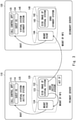
- Fig. 3 shows the fault tolerant system 100 during normal operation.
- the storage 120 of the primary server 110 includes a storage synchronous area 122, which is the active system of the DRBD.
- the storage synchronous area 122 is configured in, for example, a predetermined folder such as "/drbd_share”.
- a virtual system's disk image (hereinafter also simply referred to as "disk image”) 123 is stored in "/drbd_share", which is the storage synchronous area 122.
- the disk image 123 corresponds to the disk image 31 in Fig. 1 .
- the storage 140 of the secondary server 130 includes a storage synchronous area 142, which is the standby system of the DRBD.
- the storage synchronous area 142 is configured in, for example, a predetermined folder such as "/drbd_share”.
- the DRBD 116 (see Fig. 2 ) of the primary server 110 transmits the disk image 123 stored in the storage synchronous area 122 to the secondary server 130.
- the DRBD 136 of the secondary server 130 stores in "/drbd_share", which is the storage synchronous area 142, a disk image 143 replicated from the disk image 123 received from the primary server 110.
- the disk image 143 corresponds to the disk image 32 in Fig. 1 .
- an ACT IP "172.31.0.10” is set to the storage synchronous area 122 of the primary server 110.
- the primary server 110 uses the ACT IP to mount the storage synchronous area 122 by the NFS.
- the storage synchronous area 122 is mounted on a predetermined mount point 124 such as "/mnt/nfs-client/”.
- the secondary server 130 uses the ACT IP to mount the storage synchronous area 122 by the NFS.
- the storage synchronous area 122 is mounted on a predetermined mount point 144 such as "/mnt/nfs-client/".
- the primary server 110 boots the virtual system 125 by using the disk image 123 in the storage synchronous area 122 mounted by NFS.
- the primary server 110 causes the virtual system 125 to run as the active system.
- the primary server 110 causes the guest OS 114 and the call control app 115 to run on the virtual system 125.
- the primary server 110 obtains a snapshot of memory content of the virtual system 125 and transmits the snapshot to the secondary server 130 on a regular basis.
- the virtual system 125 corresponds to the virtual system 41 in Fig. 1 .
- the secondary server 130 boots the virtual system 145 as the standby system by using the disk image 123 in the storage synchronous area 122 mounted by NFS.
- the secondary server 130 stands by for execution of the guest OS 134 and the call control app 135 on the virtual system 145.
- the virtual system 145 corresponds to the virtual system 42 in Fig. 1 .
- the secondary server 130 receives from the primary server 110 and stores a snapshot of memory content of the virtual system 125 on a regular basis.
- the secondary server 130 for example on every reception of a new snapshot, overwrites the snapshot previously received with the snapshot newly received.
- Fig. 4 shows the fault tolerant system 100 in a case of a failure occurring in the primary server 110.
- the monitoring app 137 detects a failure in the primary server 110.
- the secondary server 130 switches the active system of the DRBD to the storage 140 of the secondary server.
- the secondary server 130 sets an ACT IP "172.31.0.10" to the storage synchronous area 142 in its own storage 140.
- the secondary server 130 uses the ACT IP "172.31.0.10" to mount the storage synchronous area 142 on the mount point 144 by the NFS.
- the secondary server 130 switches the virtual system 145 from the standby system to the active system.
- the secondary server 130 uses the snapshot, which has been received prior to occurrence of the failure, to reproduce on the virtual system 145 the memory content in the virtual system 145 of when the snapshot was last obtained.
- the call control app 135 takes over the call control process having been provided by the virtual system 125 of the primary server 110, with reference to the memory content thus reproduced.
- Fig. 5 shows an operation procedure during normal operation in the primary server 110.
- the primary server 110 uses the ACT IP to mount the storage synchronous area 122 in the storage 120 on the mount point 124 by the NFS (Step S11).
- the primary server 110 boots the virtual system 125 as an active system by using the disk image 123 stored in the storage synchronous area 122 thus mounted (step S12).
- the primary server 110 boots the guest OS 114 on the virtual system 125, and executes the call control app 115 on the guest OS 114 (Step S13).
- the primary server 110 obtains a snapshot of memory content in the virtual system 125 (Step S14).
- the primary server 110 determines, for example, whether or not a predetermined checkpoint cycle has elapsed, and obtains the snapshot at every lapse of the checkpoint cycle. In obtaining the snapshot, the primary server 110 obtains the memory content having been changed since the previous snapshot was obtained.
- the primary server 110 transmits the snapshot thus obtained to the secondary server 130 (Step S15). When the content of the storage synchronous area 122 in the storage 120 has been changed, the primary server 110 transmits content of the change to the secondary server 130 in parallel with obtaining and transmitting the snapshot.
- Fig. 6 shows an operation procedure during normal operation in the secondary server 130.
- the secondary server 130 uses the ACT IP to mount the storage synchronous area 122 in the storage 120 of the primary server 110 on the mount point 144 by the NFS (Step S21).
- the secondary server 130 boots the virtual system 145 as a standby system by using the disk image 123 stored in the storage synchronous area 122 thus mounted (Step S22).
- the secondary server 130 boots the guest OS 134 on the virtual system 145, and stands by for execution of the call control app 135 on the guest OS 134 (Step S23).
- the secondary server 130 receives a snapshot of memory content in the virtual system 125 from the primary server 110 (Step S24).
- the secondary server 130 stores the snapshot thus received.
- the secondary server 130 receives content of the change in the storage synchronous area 122 in the storage 120 in parallel with receiving the snapshot.
- the secondary server 130 synchronizes the content of the storage synchronous area 142 in the storage 140 with the content of the storage synchronous area 122 in the storage 120.
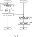
- Fig. 7 shows an operation procedure in a case of a failure occurring in operation of the call control app 115 in the primary server 110.
- the primary server 110 uses the monitoring app 117 (see Fig. 2 ) to monitor operation of the call control app 115 executed on the guest OS 114 (Step S31).
- the primary server 110 determines whether or not the operation of the call control app 115 is abnormal (Step S32). When the operation of the call control app 115 is determined not to be abnormal, the primary server 110 returns to Step S31 and continues monitoring the operation of the call control app 115.
- the primary server 110 notifies the secondary server 130 of the operation abnormality (Step S33).
- the secondary server 130 switches the virtual system 145 (see Fig. 4 ) from the standby system to the active system (Step S34).
- the secondary server 130 uses the snapshot received in Step S24 shown in Fig. 6 to execute the call control app 135 on the virtual system 145 switched to the active system (Step S35).
- Fig. 8 shows an operation procedure in a case of a failure occurring in the primary server 110.
- the secondary server 130 uses the monitoring app 137 (see Fig. 2 ) to monitor the primary server 110 (Step S41).
- the secondary server 130 determines whether or not a failure has occurred in the primary server 110 (Step S42). When the primary server 110 is determined not to be abnormal, the secondary server 130 returns to Step S41 and continues monitoring the primary server 110.
- Step S43 the secondary server 130 switches the active system of the DRBD from the storage synchronous area 122 in the storage 120 of the primary server 110 to the storage synchronous area 142 in the storage 140 of the secondary server 130.
- Step S44 the secondary server 130 sets a virtual address to the storage synchronous area 142 (Step S44).
- the secondary server 130 uses the virtual address to mount the storage synchronous area 142 on the mount point 144 by the NFS (Step S45).
- the secondary server 130 switches the virtual system 145 from the standby system to the active system (Step S46).
- the secondary server 130 uses the snapshot received in Step S24 shown in Fig. 6 to execute the call control app 135 on the virtual system 145 switched to the active system (Step S47).
- the disk image 143 stored in the storage synchronous area 142 is synchronized with the disk image 123 stored in the storage synchronous area 122 in the primary server 110.
- the call control app 135 can thus take over the call control process normally from the call control app 115 on the primary server 110 side.
- the storage synchronous areas in the storage 120 of the primary server 110 and in the storage 140 of the secondary server 130 are synchronized by employing the single primary mode of the DRBD.
- the single primary mode of the DRBD is employed not for data synchronization, which is the typical application, but for synchronization of the disk image for booting the virtual system.
- the storage synchronous area on the primary server 110 side is used as the active system of the DRBD, and the storage synchronous area on the secondary server 130 side is used as the standby system.
- Such a configuration enables synchronization of the content of the storage synchronous area during system operation.
- the virtual address is set to the storage synchronous area that stores the disk image of the virtual system on the primary server 110 side.
- the primary server 110 and the secondary server 130 each use the virtual address to mount the storage synchronous area on the primary server 110 side by the NFS.
- the secondary server 130 which is the standby system of the DRBD, to boot the virtual system by using the same disk image as the primary server 110.
- the secondary server 130 uses the virtual address to mount the storage synchronous area on the primary server 110 side by the NFS.
- An external disk device such as a shared disk array device is therefore not required.
- the memory content of the virtual system on the primary server 110 side and the memory content of the virtual system on the secondary server 130 side are synchronized through use of a live migration function or the like.
- the storage synchronous area on the secondary server 130 side becomes the active system of the DRBD, and a virtual address is set to the storage synchronous area on the secondary server 130 side.
- the secondary server 130 can maintain the mount state of the NFS with respect to the booted virtual system, while remaining in a state of being booted with the disk image on the primary server 110 side. Therefore, the secondary server 130 can maintain the NFS mount state without noticing that the disk image referred to by the virtual system has been switched from the primary server 110 side to the secondary server 130 side.
- the system status is not compiled into a database, and a real-time application configured to retain the state on memory is running. Even in such a case, by using memory synchronization in the virtual system together with storage synchronization, the running state of the virtual system can be continued on the secondary server 130 even after switching the active system of the DRBD due to a failure occurring in the primary server 110.
- FIG. 9 shows a configuration example of a server apparatus.
- a server apparatus 300 is provided with a CPU (Central Processing Unit) 301, main memory 302, a storage device 303, an input interface 304, a display controller 305, a data reader/writer 306, a communication interface 307, and a communication interface 308.
- CPU Central Processing Unit
- main memory 302 main memory
- storage device 303 main memory
- input interface 304 main memory
- display controller 305 main memory
- a data reader/writer 306 a communication interface 307
- a communication interface 308 a communication interface
- the CPU 301 deploys a program (code) stored in the storage device 303 on the main memory 302 and then executes the program to carry out various calculations.
- the main memory 302 is typically a volatile storage device such as DRAM (Dynamic Random Access Memory).
- a program for causing the server apparatus 300 to function as the primary server 110 or the secondary server 130 is provided, for example, in a state of being stored in a computer-readable recording medium 320.
- the program may also be provided via a network such as the Internet.
- the aforementioned program may be stored by using various types of non-transitory computer-readable media and provided to a computer (server apparatus).
- the non-transitory computer-readable medium includes various types of tangible recording media. Examples of the non-transitory computer-readable medium include: a magnetic recording medium such as a flexible disk, a magnetic tape, or a hard disk; a magneto-optical recording medium such as a magneto-optical disk; an optical disk medium such as a CD (compact disc) or a DVD (digital versatile disk); and semiconductor memory such as mask ROM (read only memory), PROM (programmable ROM), EPROM (erasable PROM), flash ROM, or RAM (random access memory).
- a magnetic recording medium such as a flexible disk, a magnetic tape, or a hard disk
- a magneto-optical recording medium such as a magneto-optical disk
- an optical disk medium such as a CD (compact disc) or a DVD (digital versatile disk)
- semiconductor memory such as mask
- the program may be provided to a computer through use of various types of transitory computer-readable media.
- Examples of the transitory computer-readable medium include an electrical signal, an optical signal, and an electromagnetic wave.
- the transitory computer-readable media can provide the program to a computer via a wired communication channel such as an electric wire and a fiber-optic cable, or a wireless communication channel.
- the storage device 303 is configured as, for example, a disk device such as a hard disk drive, or a semiconductor storage device such as flash memory.
- the storage device 303 corresponds to the storage 120 of the primary server 110 or the storage 140 of the secondary server 130.
- the input interface 304 mediates data transmission between the CPU 301 and an input device 310 such as a keyboard and a mouse.
- the display controller 305 is connected to the display device 330 and controls display on the display device 330.
- the data reader/writer 306 mediates data transmission between the CPU 301 and the recording medium 320.
- the data reader/writer 306, for example, reads the program from the recording medium 320 and transmits the program thus read to the CPU 301.
- the communication interfaces 307, 308 mediate data transmission between the CPU 301 and other devices or networks.
- the communication interface 307 corresponds to the NIC 118 of the primary server 110
- the communication interface 308 corresponds to the NIC 119 of the primary server 110.
- the communication interface 307 corresponds to the NIC 138 of the secondary server 130
- the communication interface 308 corresponds to the NIC 139 of the secondary server 130.
- a fault tolerant system comprising:
- the fault tolerant system according to supplementary note 1, wherein the first server obtains and transmits the snapshot to the second server at predetermined time intervals.
- the fault tolerant system according to supplementary note 1 or 2, wherein the second server monitors the first server and, when a failure occurs in the first server, switches the storage of the second server from the standby system to the active system.
- the fault tolerant system according to any one of supplementary notes 1 to 4, wherein the content of the storage synchronous area in the first storage is replicated to the storage synchronous area in the second storage by employing a single primary mode of a DRBD (Distributed Replicated Block Device).
- DRBD Distributed Replicated Block Device
- the fault tolerant system according to any one of supplementary notes 1 to 5, wherein the application is a call control application configured to control a call of a device having a telephone function connected to the first server and the second server via a network.
- the fault tolerant system according to any one of supplementary notes 1 to 6, wherein the application manages a system status on memory without compiling the system status into a database.
- a server comprising:
- the server according to supplementary note 8, wherein the server obtains and transmits the snapshot to the another server at predetermined time intervals.
- DRBD Distributed Replicated Block Device
- a server comprising:
- the server according to supplementary note 11, wherein the server monitors the another server and, when a failure occurs in the another server, switches the storage of the server from the standby system to the active system.
- the server monitors execution of the application running on the virtual system operating on the another server, and, when a fault occurs in execution of the application running on the virtual system operating on the another server, switches the application running on the virtual system operating on the server from a standby state to an active state.
- An operation method of a fault tolerant system comprising:
- the operation method of a fault tolerant system according to any one of supplementary notes 14 to 18, wherein the application is a call control application configured to control a call of a device having a telephone function connected to the first server and the second server via a network.
- the application is a call control application configured to control a call of a device having a telephone function connected to the first server and the second server via a network.
- An operation method of a server comprising:
- An operation method of a server comprising:
- a program configured to cause a server to carry out the operation method of a server according to any one of supplementary notes 21 to 26.
Landscapes
- Engineering & Computer Science (AREA)
- Theoretical Computer Science (AREA)
- Quality & Reliability (AREA)
- Physics & Mathematics (AREA)
- General Engineering & Computer Science (AREA)
- General Physics & Mathematics (AREA)
- Hardware Redundancy (AREA)
Applications Claiming Priority (2)
| Application Number | Priority Date | Filing Date | Title |
|---|---|---|---|
| JP2019100508A JP6773345B1 (ja) | 2019-05-29 | 2019-05-29 | フォールトトレラントシステム、サーバ、及びそれらの運用方法 |
| PCT/JP2020/014384 WO2020241032A1 (ja) | 2019-05-29 | 2020-03-27 | フォールトトレラントシステム、サーバ、フォールトトレラントシステムの運用方法、サーバの運用方法、及びサーバの運用方法のプログラム |
Publications (4)
| Publication Number | Publication Date |
|---|---|
| EP3961402A1 true EP3961402A1 (de) | 2022-03-02 |
| EP3961402A4 EP3961402A4 (de) | 2022-06-22 |
| EP3961402B1 EP3961402B1 (de) | 2023-10-18 |
| EP3961402C0 EP3961402C0 (de) | 2023-10-18 |
Family
ID=72829284
Family Applications (1)
| Application Number | Title | Priority Date | Filing Date |
|---|---|---|---|
| EP20813979.0A Active EP3961402B1 (de) | 2019-05-29 | 2020-03-27 | Fehlertolerantes system, server, betriebsverfahren für fehlertolerantes system, serverbetriebsverfahren und programm für serverbetriebsverfahren |
Country Status (7)
| Country | Link |
|---|---|
| US (1) | US11687425B2 (de) |
| EP (1) | EP3961402B1 (de) |
| JP (1) | JP6773345B1 (de) |
| CN (1) | CN113874842B (de) |
| AU (1) | AU2020285024B2 (de) |
| CA (1) | CA3142206C (de) |
| WO (1) | WO2020241032A1 (de) |
Families Citing this family (2)
| Publication number | Priority date | Publication date | Assignee | Title |
|---|---|---|---|---|
| US11323507B2 (en) * | 2020-04-07 | 2022-05-03 | Supercell Oy | Server system and method of managing server system |
| CN115639969B (zh) * | 2022-11-17 | 2023-05-09 | 广州粤芯半导体技术有限公司 | 一种存储盘主备切换方法、装置、计算机设备 |
Family Cites Families (13)
| Publication number | Priority date | Publication date | Assignee | Title |
|---|---|---|---|---|
| US7246256B2 (en) * | 2004-01-20 | 2007-07-17 | International Business Machines Corporation | Managing failover of J2EE compliant middleware in a high availability system |
| US6996502B2 (en) * | 2004-01-20 | 2006-02-07 | International Business Machines Corporation | Remote enterprise management of high availability systems |
| US20070094659A1 (en) * | 2005-07-18 | 2007-04-26 | Dell Products L.P. | System and method for recovering from a failure of a virtual machine |
| JP2009003631A (ja) * | 2007-06-20 | 2009-01-08 | Nec Corp | 冗長構成サーバシステム、同期処理方法、及びプログラム |
| US8499297B2 (en) | 2008-10-28 | 2013-07-30 | Vmware, Inc. | Low overhead fault tolerance through hybrid checkpointing and replay |
| US8438349B2 (en) * | 2009-08-21 | 2013-05-07 | Symantec Corporation | Proxy backup of virtual disk image files on NAS devices |
| JP4780237B2 (ja) | 2010-04-26 | 2011-09-28 | 株式会社日立製作所 | 障害回復方法 |
| US8413145B2 (en) * | 2010-09-30 | 2013-04-02 | Avaya Inc. | Method and apparatus for efficient memory replication for high availability (HA) protection of a virtual machine (VM) |
| JP5742410B2 (ja) * | 2011-04-11 | 2015-07-01 | 日本電気株式会社 | フォールトトレラント計算機システム、フォールトトレラント計算機システムの制御方法、及びフォールトトレラント計算機システムの制御プログラム |
| JP2013186692A (ja) * | 2012-03-08 | 2013-09-19 | Hitachi Systems Ltd | 仮想マシン提供システム |
| JP6299640B2 (ja) | 2015-03-23 | 2018-03-28 | 横河電機株式会社 | 通信装置 |
| US10228871B2 (en) * | 2016-02-22 | 2019-03-12 | Netapp Inc. | Enabling data integrity checking and faster application recovery in synchronous replicated datasets |
| JP2019100508A (ja) | 2017-12-07 | 2019-06-24 | 株式会社ジェイテクト | 転がり軸受及び転動装置 |
-
2019
- 2019-05-29 JP JP2019100508A patent/JP6773345B1/ja active Active
-
2020
- 2020-03-27 CA CA3142206A patent/CA3142206C/en active Active
- 2020-03-27 EP EP20813979.0A patent/EP3961402B1/de active Active
- 2020-03-27 WO PCT/JP2020/014384 patent/WO2020241032A1/ja not_active Ceased
- 2020-03-27 CN CN202080039091.3A patent/CN113874842B/zh active Active
- 2020-03-27 AU AU2020285024A patent/AU2020285024B2/en active Active
- 2020-03-27 US US17/612,715 patent/US11687425B2/en active Active
Also Published As
| Publication number | Publication date |
|---|---|
| CA3142206C (en) | 2024-02-13 |
| US11687425B2 (en) | 2023-06-27 |
| EP3961402A4 (de) | 2022-06-22 |
| EP3961402B1 (de) | 2023-10-18 |
| CN113874842B (zh) | 2023-10-17 |
| JP2020194430A (ja) | 2020-12-03 |
| AU2020285024A1 (en) | 2021-12-09 |
| US20220327034A1 (en) | 2022-10-13 |
| JP6773345B1 (ja) | 2020-10-21 |
| CN113874842A (zh) | 2021-12-31 |
| AU2020285024B2 (en) | 2025-06-26 |
| WO2020241032A1 (ja) | 2020-12-03 |
| CA3142206A1 (en) | 2020-12-03 |
| EP3961402C0 (de) | 2023-10-18 |
Similar Documents
| Publication | Publication Date | Title |
|---|---|---|
| US11533311B2 (en) | Automatically deployed information technology (IT) system and method | |
| US9519656B2 (en) | System and method for providing a virtualized replication and high availability environment | |
| US8874746B1 (en) | Collaboration between discrete systems and a shared system to consolidate shared storage-related services | |
| JP5817308B2 (ja) | サーバ、サーバシステムおよびサーバの冗長切り替え方法 | |
| US9992058B2 (en) | Redundant storage solution | |
| US20170163475A1 (en) | Redundant storage solution | |
| US8990608B1 (en) | Failover of applications between isolated user space instances on a single instance of an operating system | |
| US9104609B2 (en) | Information processing apparatus, system time synchronization method and computer readable medium | |
| US20130061086A1 (en) | Fault-tolerant system, server, and fault-tolerating method | |
| US11687425B2 (en) | Fault tolerant system, server, and operation method of fault tolerant system | |
| US20220215001A1 (en) | Replacing dedicated witness node in a stretched cluster with distributed management controllers | |
| US20230341889A1 (en) | Virtual precision time protocol clock devices for virtual nodes | |
| US11086615B2 (en) | Virtual appliance upgrades in high-availability (HA) computing clusters | |
| JP6295759B2 (ja) | ネットワーク管理装置,情報処理システム及びプログラム | |
| JP6954693B2 (ja) | フォールトトレラントシステム、サーバ、それらの運用方法、及びプログラム | |
| US12204927B2 (en) | Software updating apparatus, software updating method, and program | |
| US20140189422A1 (en) | Information processing apparatus and stored information analyzing method | |
| JP2009003631A (ja) | 冗長構成サーバシステム、同期処理方法、及びプログラム | |
| JP2013196272A (ja) | フォールトトレラントサーバ、フォールトトレラントサーバの動作方法、及びbmc | |
| US20160077861A1 (en) | Information processing system, storage apparatus, and program | |
| CN111104199B (zh) | 虚拟机高可用的方法及装置 | |
| JP2013190921A (ja) | クラスタシステム |
Legal Events
| Date | Code | Title | Description |
|---|---|---|---|
| STAA | Information on the status of an ep patent application or granted ep patent |
Free format text: STATUS: THE INTERNATIONAL PUBLICATION HAS BEEN MADE |
|
| PUAI | Public reference made under article 153(3) epc to a published international application that has entered the european phase |
Free format text: ORIGINAL CODE: 0009012 |
|
| STAA | Information on the status of an ep patent application or granted ep patent |
Free format text: STATUS: REQUEST FOR EXAMINATION WAS MADE |
|
| 17P | Request for examination filed |
Effective date: 20211124 |
|
| AK | Designated contracting states |
Kind code of ref document: A1 Designated state(s): AL AT BE BG CH CY CZ DE DK EE ES FI FR GB GR HR HU IE IS IT LI LT LU LV MC MK MT NL NO PL PT RO RS SE SI SK SM TR |
|
| STAA | Information on the status of an ep patent application or granted ep patent |
Free format text: STATUS: EXAMINATION IS IN PROGRESS |
|
| A4 | Supplementary search report drawn up and despatched |
Effective date: 20220523 |
|
| RIC1 | Information provided on ipc code assigned before grant |
Ipc: G06F 3/06 20060101ALI20220517BHEP Ipc: G06F 11/20 20060101AFI20220517BHEP |
|
| 17Q | First examination report despatched |
Effective date: 20220603 |
|
| DAV | Request for validation of the european patent (deleted) | ||
| DAX | Request for extension of the european patent (deleted) | ||
| GRAP | Despatch of communication of intention to grant a patent |
Free format text: ORIGINAL CODE: EPIDOSNIGR1 |
|
| STAA | Information on the status of an ep patent application or granted ep patent |
Free format text: STATUS: GRANT OF PATENT IS INTENDED |
|
| INTG | Intention to grant announced |
Effective date: 20230525 |
|
| GRAS | Grant fee paid |
Free format text: ORIGINAL CODE: EPIDOSNIGR3 |
|
| GRAA | (expected) grant |
Free format text: ORIGINAL CODE: 0009210 |
|
| STAA | Information on the status of an ep patent application or granted ep patent |
Free format text: STATUS: THE PATENT HAS BEEN GRANTED |
|
| AK | Designated contracting states |
Kind code of ref document: B1 Designated state(s): AL AT BE BG CH CY CZ DE DK EE ES FI FR GB GR HR HU IE IS IT LI LT LU LV MC MK MT NL NO PL PT RO RS SE SI SK SM TR |
|
| REG | Reference to a national code |
Ref country code: GB Ref legal event code: FG4D |
|
| REG | Reference to a national code |
Ref country code: CH Ref legal event code: EP |
|
| REG | Reference to a national code |
Ref country code: IE Ref legal event code: FG4D |
|
| REG | Reference to a national code |
Ref country code: DE Ref legal event code: R096 Ref document number: 602020019568 Country of ref document: DE |
|
| U01 | Request for unitary effect filed |
Effective date: 20231024 |
|
| U07 | Unitary effect registered |
Designated state(s): AT BE BG DE DK EE FI FR IT LT LU LV MT NL PT SE SI Effective date: 20231030 |
|
| PG25 | Lapsed in a contracting state [announced via postgrant information from national office to epo] |
Ref country code: GR Free format text: LAPSE BECAUSE OF FAILURE TO SUBMIT A TRANSLATION OF THE DESCRIPTION OR TO PAY THE FEE WITHIN THE PRESCRIBED TIME-LIMIT Effective date: 20240119 |
|
| PG25 | Lapsed in a contracting state [announced via postgrant information from national office to epo] |
Ref country code: IS Free format text: LAPSE BECAUSE OF FAILURE TO SUBMIT A TRANSLATION OF THE DESCRIPTION OR TO PAY THE FEE WITHIN THE PRESCRIBED TIME-LIMIT Effective date: 20240218 |
|
| PG25 | Lapsed in a contracting state [announced via postgrant information from national office to epo] |
Ref country code: ES Free format text: LAPSE BECAUSE OF FAILURE TO SUBMIT A TRANSLATION OF THE DESCRIPTION OR TO PAY THE FEE WITHIN THE PRESCRIBED TIME-LIMIT Effective date: 20231018 |
|
| PG25 | Lapsed in a contracting state [announced via postgrant information from national office to epo] |
Ref country code: IS Free format text: LAPSE BECAUSE OF FAILURE TO SUBMIT A TRANSLATION OF THE DESCRIPTION OR TO PAY THE FEE WITHIN THE PRESCRIBED TIME-LIMIT Effective date: 20240218 Ref country code: GR Free format text: LAPSE BECAUSE OF FAILURE TO SUBMIT A TRANSLATION OF THE DESCRIPTION OR TO PAY THE FEE WITHIN THE PRESCRIBED TIME-LIMIT Effective date: 20240119 Ref country code: ES Free format text: LAPSE BECAUSE OF FAILURE TO SUBMIT A TRANSLATION OF THE DESCRIPTION OR TO PAY THE FEE WITHIN THE PRESCRIBED TIME-LIMIT Effective date: 20231018 |
|
| U20 | Renewal fee for the european patent with unitary effect paid |
Year of fee payment: 5 Effective date: 20240325 |
|
| PG25 | Lapsed in a contracting state [announced via postgrant information from national office to epo] |
Ref country code: RS Free format text: LAPSE BECAUSE OF FAILURE TO SUBMIT A TRANSLATION OF THE DESCRIPTION OR TO PAY THE FEE WITHIN THE PRESCRIBED TIME-LIMIT Effective date: 20231018 Ref country code: PL Free format text: LAPSE BECAUSE OF FAILURE TO SUBMIT A TRANSLATION OF THE DESCRIPTION OR TO PAY THE FEE WITHIN THE PRESCRIBED TIME-LIMIT Effective date: 20231018 Ref country code: NO Free format text: LAPSE BECAUSE OF FAILURE TO SUBMIT A TRANSLATION OF THE DESCRIPTION OR TO PAY THE FEE WITHIN THE PRESCRIBED TIME-LIMIT Effective date: 20240118 Ref country code: HR Free format text: LAPSE BECAUSE OF FAILURE TO SUBMIT A TRANSLATION OF THE DESCRIPTION OR TO PAY THE FEE WITHIN THE PRESCRIBED TIME-LIMIT Effective date: 20231018 |
|
| REG | Reference to a national code |
Ref country code: DE Ref legal event code: R097 Ref document number: 602020019568 Country of ref document: DE |
|
| PG25 | Lapsed in a contracting state [announced via postgrant information from national office to epo] |
Ref country code: CZ Free format text: LAPSE BECAUSE OF FAILURE TO SUBMIT A TRANSLATION OF THE DESCRIPTION OR TO PAY THE FEE WITHIN THE PRESCRIBED TIME-LIMIT Effective date: 20231018 |
|
| PG25 | Lapsed in a contracting state [announced via postgrant information from national office to epo] |
Ref country code: SK Free format text: LAPSE BECAUSE OF FAILURE TO SUBMIT A TRANSLATION OF THE DESCRIPTION OR TO PAY THE FEE WITHIN THE PRESCRIBED TIME-LIMIT Effective date: 20231018 |
|
| PG25 | Lapsed in a contracting state [announced via postgrant information from national office to epo] |
Ref country code: SM Free format text: LAPSE BECAUSE OF FAILURE TO SUBMIT A TRANSLATION OF THE DESCRIPTION OR TO PAY THE FEE WITHIN THE PRESCRIBED TIME-LIMIT Effective date: 20231018 Ref country code: SK Free format text: LAPSE BECAUSE OF FAILURE TO SUBMIT A TRANSLATION OF THE DESCRIPTION OR TO PAY THE FEE WITHIN THE PRESCRIBED TIME-LIMIT Effective date: 20231018 Ref country code: RO Free format text: LAPSE BECAUSE OF FAILURE TO SUBMIT A TRANSLATION OF THE DESCRIPTION OR TO PAY THE FEE WITHIN THE PRESCRIBED TIME-LIMIT Effective date: 20231018 Ref country code: CZ Free format text: LAPSE BECAUSE OF FAILURE TO SUBMIT A TRANSLATION OF THE DESCRIPTION OR TO PAY THE FEE WITHIN THE PRESCRIBED TIME-LIMIT Effective date: 20231018 |
|
| PLBE | No opposition filed within time limit |
Free format text: ORIGINAL CODE: 0009261 |
|
| STAA | Information on the status of an ep patent application or granted ep patent |
Free format text: STATUS: NO OPPOSITION FILED WITHIN TIME LIMIT |
|
| 26N | No opposition filed |
Effective date: 20240719 |
|
| REG | Reference to a national code |
Ref country code: CH Ref legal event code: PL |
|
| PG25 | Lapsed in a contracting state [announced via postgrant information from national office to epo] |
Ref country code: MC Free format text: LAPSE BECAUSE OF FAILURE TO SUBMIT A TRANSLATION OF THE DESCRIPTION OR TO PAY THE FEE WITHIN THE PRESCRIBED TIME-LIMIT Effective date: 20231018 |
|
| PG25 | Lapsed in a contracting state [announced via postgrant information from national office to epo] |
Ref country code: MC Free format text: LAPSE BECAUSE OF FAILURE TO SUBMIT A TRANSLATION OF THE DESCRIPTION OR TO PAY THE FEE WITHIN THE PRESCRIBED TIME-LIMIT Effective date: 20231018 |
|
| PG25 | Lapsed in a contracting state [announced via postgrant information from national office to epo] |
Ref country code: IE Free format text: LAPSE BECAUSE OF NON-PAYMENT OF DUE FEES Effective date: 20240327 |
|
| PG25 | Lapsed in a contracting state [announced via postgrant information from national office to epo] |
Ref country code: IE Free format text: LAPSE BECAUSE OF NON-PAYMENT OF DUE FEES Effective date: 20240327 Ref country code: CH Free format text: LAPSE BECAUSE OF NON-PAYMENT OF DUE FEES Effective date: 20240331 |
|
| U20 | Renewal fee for the european patent with unitary effect paid |
Year of fee payment: 6 Effective date: 20250325 |
|
| PG25 | Lapsed in a contracting state [announced via postgrant information from national office to epo] |
Ref country code: CY Free format text: LAPSE BECAUSE OF FAILURE TO SUBMIT A TRANSLATION OF THE DESCRIPTION OR TO PAY THE FEE WITHIN THE PRESCRIBED TIME-LIMIT; INVALID AB INITIO Effective date: 20200327 |
|
| PG25 | Lapsed in a contracting state [announced via postgrant information from national office to epo] |
Ref country code: HU Free format text: LAPSE BECAUSE OF FAILURE TO SUBMIT A TRANSLATION OF THE DESCRIPTION OR TO PAY THE FEE WITHIN THE PRESCRIBED TIME-LIMIT; INVALID AB INITIO Effective date: 20200327 |
|
| PG25 | Lapsed in a contracting state [announced via postgrant information from national office to epo] |
Ref country code: TR Free format text: LAPSE BECAUSE OF FAILURE TO SUBMIT A TRANSLATION OF THE DESCRIPTION OR TO PAY THE FEE WITHIN THE PRESCRIBED TIME-LIMIT Effective date: 20231018 |
|
| PGFP | Annual fee paid to national office [announced via postgrant information from national office to epo] |
Ref country code: GB Payment date: 20260324 Year of fee payment: 7 |
|
| U20 | Renewal fee for the european patent with unitary effect paid |
Year of fee payment: 7 Effective date: 20260326 |