EP3961777A1 - Zelle, zellenstapelvorrichtung, modul und modulgehäuse - Google Patents
Zelle, zellenstapelvorrichtung, modul und modulgehäuse Download PDFInfo
- Publication number
- EP3961777A1 EP3961777A1 EP20794119.6A EP20794119A EP3961777A1 EP 3961777 A1 EP3961777 A1 EP 3961777A1 EP 20794119 A EP20794119 A EP 20794119A EP 3961777 A1 EP3961777 A1 EP 3961777A1
- Authority
- EP
- European Patent Office
- Prior art keywords
- intermediate layer
- cell
- layer
- metal plate
- electrode layer
- Prior art date
- Legal status (The legal status is an assumption and is not a legal conclusion. Google has not performed a legal analysis and makes no representation as to the accuracy of the status listed.)
- Pending
Links
- 229910052751 metal Inorganic materials 0.000 claims abstract description 115
- 239000002184 metal Substances 0.000 claims abstract description 114
- 239000002245 particle Substances 0.000 claims abstract description 75
- 239000007784 solid electrolyte Substances 0.000 claims abstract description 33
- QDOXWKRWXJOMAK-UHFFFAOYSA-N dichromium trioxide Chemical compound O=[Cr]O[Cr]=O QDOXWKRWXJOMAK-UHFFFAOYSA-N 0.000 claims description 70
- 229910052809 inorganic oxide Inorganic materials 0.000 claims description 18
- 239000010410 layer Substances 0.000 description 237
- 239000007789 gas Substances 0.000 description 47
- 239000000446 fuel Substances 0.000 description 45
- 239000000853 adhesive Substances 0.000 description 27
- 230000001070 adhesive effect Effects 0.000 description 27
- 239000002737 fuel gas Substances 0.000 description 22
- GWEVSGVZZGPLCZ-UHFFFAOYSA-N Titan oxide Chemical compound O=[Ti]=O GWEVSGVZZGPLCZ-UHFFFAOYSA-N 0.000 description 20
- 229910045601 alloy Inorganic materials 0.000 description 19
- 239000000956 alloy Substances 0.000 description 19
- 239000000463 material Substances 0.000 description 18
- 239000012298 atmosphere Substances 0.000 description 16
- QVGXLLKOCUKJST-UHFFFAOYSA-N atomic oxygen Chemical compound [O] QVGXLLKOCUKJST-UHFFFAOYSA-N 0.000 description 15
- 239000001301 oxygen Substances 0.000 description 15
- 229910052760 oxygen Inorganic materials 0.000 description 15
- 239000011651 chromium Substances 0.000 description 13
- 229910002076 stabilized zirconia Inorganic materials 0.000 description 13
- 239000010936 titanium Substances 0.000 description 13
- 230000002829 reductive effect Effects 0.000 description 11
- 239000011572 manganese Substances 0.000 description 10
- 230000035699 permeability Effects 0.000 description 10
- 229910052719 titanium Inorganic materials 0.000 description 10
- SIWVEOZUMHYXCS-UHFFFAOYSA-N oxo(oxoyttriooxy)yttrium Chemical group O=[Y]O[Y]=O SIWVEOZUMHYXCS-UHFFFAOYSA-N 0.000 description 9
- 239000006104 solid solution Substances 0.000 description 9
- 238000007669 thermal treatment Methods 0.000 description 9
- 230000005611 electricity Effects 0.000 description 8
- 229910052748 manganese Inorganic materials 0.000 description 8
- 239000000843 powder Substances 0.000 description 8
- 229910052782 aluminium Inorganic materials 0.000 description 7
- 239000000758 substrate Substances 0.000 description 7
- WGLPBDUCMAPZCE-UHFFFAOYSA-N Trioxochromium Chemical compound O=[Cr](=O)=O WGLPBDUCMAPZCE-UHFFFAOYSA-N 0.000 description 6
- MCMNRKCIXSYSNV-UHFFFAOYSA-N Zirconium dioxide Chemical compound O=[Zr]=O MCMNRKCIXSYSNV-UHFFFAOYSA-N 0.000 description 6
- 229910000423 chromium oxide Inorganic materials 0.000 description 6
- 229910052802 copper Inorganic materials 0.000 description 5
- 229910052759 nickel Inorganic materials 0.000 description 5
- 238000010248 power generation Methods 0.000 description 5
- 229910001404 rare earth metal oxide Inorganic materials 0.000 description 5
- 229910001220 stainless steel Inorganic materials 0.000 description 5
- 229910052727 yttrium Inorganic materials 0.000 description 5
- UFHFLCQGNIYNRP-UHFFFAOYSA-N Hydrogen Chemical compound [H][H] UFHFLCQGNIYNRP-UHFFFAOYSA-N 0.000 description 4
- 239000011575 calcium Substances 0.000 description 4
- 239000011248 coating agent Substances 0.000 description 4
- 238000000576 coating method Methods 0.000 description 4
- 230000000052 comparative effect Effects 0.000 description 4
- 239000002131 composite material Substances 0.000 description 4
- 238000005260 corrosion Methods 0.000 description 4
- 230000007797 corrosion Effects 0.000 description 4
- 239000013078 crystal Substances 0.000 description 4
- 238000005868 electrolysis reaction Methods 0.000 description 4
- 238000002149 energy-dispersive X-ray emission spectroscopy Methods 0.000 description 4
- 239000000835 fiber Substances 0.000 description 4
- 239000001257 hydrogen Substances 0.000 description 4
- 229910052739 hydrogen Inorganic materials 0.000 description 4
- 239000011777 magnesium Substances 0.000 description 4
- 238000000034 method Methods 0.000 description 4
- 239000000203 mixture Substances 0.000 description 4
- 238000002161 passivation Methods 0.000 description 4
- 229910052710 silicon Inorganic materials 0.000 description 4
- 239000007787 solid Substances 0.000 description 4
- 239000010935 stainless steel Substances 0.000 description 4
- OGIDPMRJRNCKJF-UHFFFAOYSA-N titanium oxide Inorganic materials [Ti]=O OGIDPMRJRNCKJF-UHFFFAOYSA-N 0.000 description 4
- VYPSYNLAJGMNEJ-UHFFFAOYSA-N Silicium dioxide Chemical compound O=[Si]=O VYPSYNLAJGMNEJ-UHFFFAOYSA-N 0.000 description 3
- 239000011230 binding agent Substances 0.000 description 3
- 230000000903 blocking effect Effects 0.000 description 3
- 229910052791 calcium Inorganic materials 0.000 description 3
- 238000006243 chemical reaction Methods 0.000 description 3
- 229910052804 chromium Inorganic materials 0.000 description 3
- 239000000470 constituent Substances 0.000 description 3
- 238000000921 elemental analysis Methods 0.000 description 3
- 229910052742 iron Inorganic materials 0.000 description 3
- 229910052749 magnesium Inorganic materials 0.000 description 3
- 238000004519 manufacturing process Methods 0.000 description 3
- 239000007769 metal material Substances 0.000 description 3
- 150000002739 metals Chemical class 0.000 description 3
- 238000002156 mixing Methods 0.000 description 3
- 239000003960 organic solvent Substances 0.000 description 3
- 229910052761 rare earth metal Inorganic materials 0.000 description 3
- 238000007789 sealing Methods 0.000 description 3
- 239000002002 slurry Substances 0.000 description 3
- 229910052725 zinc Inorganic materials 0.000 description 3
- PWHULOQIROXLJO-UHFFFAOYSA-N Manganese Chemical compound [Mn] PWHULOQIROXLJO-UHFFFAOYSA-N 0.000 description 2
- 229910052769 Ytterbium Inorganic materials 0.000 description 2
- XAGFODPZIPBFFR-UHFFFAOYSA-N aluminium Chemical compound [Al] XAGFODPZIPBFFR-UHFFFAOYSA-N 0.000 description 2
- 229910052788 barium Inorganic materials 0.000 description 2
- 230000005540 biological transmission Effects 0.000 description 2
- 239000000919 ceramic Substances 0.000 description 2
- 239000003792 electrolyte Substances 0.000 description 2
- 238000010304 firing Methods 0.000 description 2
- 239000011888 foil Substances 0.000 description 2
- 239000003574 free electron Substances 0.000 description 2
- 238000010191 image analysis Methods 0.000 description 2
- XEEYBQQBJWHFJM-UHFFFAOYSA-N iron Substances [Fe] XEEYBQQBJWHFJM-UHFFFAOYSA-N 0.000 description 2
- 238000013507 mapping Methods 0.000 description 2
- VNWKTOKETHGBQD-UHFFFAOYSA-N methane Chemical compound C VNWKTOKETHGBQD-UHFFFAOYSA-N 0.000 description 2
- 239000012299 nitrogen atmosphere Substances 0.000 description 2
- BASFCYQUMIYNBI-UHFFFAOYSA-N platinum Chemical compound [Pt] BASFCYQUMIYNBI-UHFFFAOYSA-N 0.000 description 2
- 239000000523 sample Substances 0.000 description 2
- 238000005245 sintering Methods 0.000 description 2
- 229910052712 strontium Inorganic materials 0.000 description 2
- 238000000177 wavelength dispersive X-ray spectroscopy Methods 0.000 description 2
- VWQVUPCCIRVNHF-UHFFFAOYSA-N yttrium atom Chemical compound [Y] VWQVUPCCIRVNHF-UHFFFAOYSA-N 0.000 description 2
- 229910052726 zirconium Inorganic materials 0.000 description 2
- 229910000859 α-Fe Inorganic materials 0.000 description 2
- OYPRJOBELJOOCE-UHFFFAOYSA-N Calcium Chemical compound [Ca] OYPRJOBELJOOCE-UHFFFAOYSA-N 0.000 description 1
- 229910052684 Cerium Inorganic materials 0.000 description 1
- VYZAMTAEIAYCRO-UHFFFAOYSA-N Chromium Chemical compound [Cr] VYZAMTAEIAYCRO-UHFFFAOYSA-N 0.000 description 1
- 229910052688 Gadolinium Inorganic materials 0.000 description 1
- 229910002262 LaCrO3 Inorganic materials 0.000 description 1
- 229910018276 LaSrCoO3 Inorganic materials 0.000 description 1
- FYYHWMGAXLPEAU-UHFFFAOYSA-N Magnesium Chemical compound [Mg] FYYHWMGAXLPEAU-UHFFFAOYSA-N 0.000 description 1
- 229910018487 Ni—Cr Inorganic materials 0.000 description 1
- KHIHIHNAFRNJFC-UHFFFAOYSA-N [Ti].[Sr].[La] Chemical compound [Ti].[Sr].[La] KHIHIHNAFRNJFC-UHFFFAOYSA-N 0.000 description 1
- 230000004913 activation Effects 0.000 description 1
- 239000012790 adhesive layer Substances 0.000 description 1
- PNEYBMLMFCGWSK-UHFFFAOYSA-N aluminium oxide Inorganic materials [O-2].[O-2].[O-2].[Al+3].[Al+3] PNEYBMLMFCGWSK-UHFFFAOYSA-N 0.000 description 1
- 229910001566 austenite Inorganic materials 0.000 description 1
- 230000015572 biosynthetic process Effects 0.000 description 1
- 229910010293 ceramic material Inorganic materials 0.000 description 1
- UPHIPHFJVNKLMR-UHFFFAOYSA-N chromium iron Chemical compound [Cr].[Fe] UPHIPHFJVNKLMR-UHFFFAOYSA-N 0.000 description 1
- VNNRSPGTAMTISX-UHFFFAOYSA-N chromium nickel Chemical compound [Cr].[Ni] VNNRSPGTAMTISX-UHFFFAOYSA-N 0.000 description 1
- NFYLSJDPENHSBT-UHFFFAOYSA-N chromium(3+);lanthanum(3+);oxygen(2-) Chemical compound [O-2].[O-2].[O-2].[Cr+3].[La+3] NFYLSJDPENHSBT-UHFFFAOYSA-N 0.000 description 1
- 239000004020 conductor Substances 0.000 description 1
- 230000000694 effects Effects 0.000 description 1
- 230000005684 electric field Effects 0.000 description 1
- 238000004993 emission spectroscopy Methods 0.000 description 1
- 238000011156 evaluation Methods 0.000 description 1
- 239000011521 glass Substances 0.000 description 1
- 238000009616 inductively coupled plasma Methods 0.000 description 1
- 239000012212 insulator Substances 0.000 description 1
- 239000003350 kerosene Substances 0.000 description 1
- 238000002844 melting Methods 0.000 description 1
- 230000008018 melting Effects 0.000 description 1
- 239000003345 natural gas Substances 0.000 description 1
- 230000001590 oxidative effect Effects 0.000 description 1
- TWNQGVIAIRXVLR-UHFFFAOYSA-N oxo(oxoalumanyloxy)alumane Chemical compound O=[Al]O[Al]=O TWNQGVIAIRXVLR-UHFFFAOYSA-N 0.000 description 1
- 229910002077 partially stabilized zirconia Inorganic materials 0.000 description 1
- 239000012466 permeate Substances 0.000 description 1
- 229910052697 platinum Inorganic materials 0.000 description 1
- 238000007639 printing Methods 0.000 description 1
- 230000027756 respiratory electron transport chain Effects 0.000 description 1
- 239000000377 silicon dioxide Substances 0.000 description 1
- 229910052814 silicon oxide Inorganic materials 0.000 description 1
- 229910052596 spinel Inorganic materials 0.000 description 1
- 239000011029 spinel Substances 0.000 description 1
- 230000009466 transformation Effects 0.000 description 1
Images


Classifications
-
- H—ELECTRICITY
- H01—ELECTRIC ELEMENTS
- H01M—PROCESSES OR MEANS, e.g. BATTERIES, FOR THE DIRECT CONVERSION OF CHEMICAL ENERGY INTO ELECTRICAL ENERGY
- H01M8/00—Fuel cells; Manufacture thereof
- H01M8/02—Details
- H01M8/0202—Collectors; Separators, e.g. bipolar separators; Interconnectors
- H01M8/0204—Non-porous and characterised by the material
- H01M8/0206—Metals or alloys
-
- H—ELECTRICITY
- H01—ELECTRIC ELEMENTS
- H01M—PROCESSES OR MEANS, e.g. BATTERIES, FOR THE DIRECT CONVERSION OF CHEMICAL ENERGY INTO ELECTRICAL ENERGY
- H01M8/00—Fuel cells; Manufacture thereof
- H01M8/10—Fuel cells with solid electrolytes
- H01M8/12—Fuel cells with solid electrolytes operating at high temperature, e.g. with stabilised ZrO2 electrolyte
- H01M8/1213—Fuel cells with solid electrolytes operating at high temperature, e.g. with stabilised ZrO2 electrolyte characterised by the electrode/electrolyte combination or the supporting material
-
- H—ELECTRICITY
- H01—ELECTRIC ELEMENTS
- H01M—PROCESSES OR MEANS, e.g. BATTERIES, FOR THE DIRECT CONVERSION OF CHEMICAL ENERGY INTO ELECTRICAL ENERGY
- H01M8/00—Fuel cells; Manufacture thereof
- H01M8/02—Details
- H01M8/0202—Collectors; Separators, e.g. bipolar separators; Interconnectors
- H01M8/0204—Non-porous and characterised by the material
- H01M8/0223—Composites
- H01M8/0228—Composites in the form of layered or coated products
-
- H—ELECTRICITY
- H01—ELECTRIC ELEMENTS
- H01M—PROCESSES OR MEANS, e.g. BATTERIES, FOR THE DIRECT CONVERSION OF CHEMICAL ENERGY INTO ELECTRICAL ENERGY
- H01M8/00—Fuel cells; Manufacture thereof
- H01M8/10—Fuel cells with solid electrolytes
- H01M8/12—Fuel cells with solid electrolytes operating at high temperature, e.g. with stabilised ZrO2 electrolyte
- H01M8/1213—Fuel cells with solid electrolytes operating at high temperature, e.g. with stabilised ZrO2 electrolyte characterised by the electrode/electrolyte combination or the supporting material
- H01M8/1226—Fuel cells with solid electrolytes operating at high temperature, e.g. with stabilised ZrO2 electrolyte characterised by the electrode/electrolyte combination or the supporting material characterised by the supporting layer
-
- H—ELECTRICITY
- H01—ELECTRIC ELEMENTS
- H01M—PROCESSES OR MEANS, e.g. BATTERIES, FOR THE DIRECT CONVERSION OF CHEMICAL ENERGY INTO ELECTRICAL ENERGY
- H01M8/00—Fuel cells; Manufacture thereof
- H01M8/24—Grouping of fuel cells, e.g. stacking of fuel cells
- H01M8/2465—Details of groupings of fuel cells
- H01M8/247—Arrangements for tightening a stack, for accommodation of a stack in a tank or for assembling different tanks
- H01M8/2475—Enclosures, casings or containers of fuel cell stacks
-
- Y—GENERAL TAGGING OF NEW TECHNOLOGICAL DEVELOPMENTS; GENERAL TAGGING OF CROSS-SECTIONAL TECHNOLOGIES SPANNING OVER SEVERAL SECTIONS OF THE IPC; TECHNICAL SUBJECTS COVERED BY FORMER USPC CROSS-REFERENCE ART COLLECTIONS [XRACs] AND DIGESTS
- Y02—TECHNOLOGIES OR APPLICATIONS FOR MITIGATION OR ADAPTATION AGAINST CLIMATE CHANGE
- Y02E—REDUCTION OF GREENHOUSE GAS [GHG] EMISSIONS, RELATED TO ENERGY GENERATION, TRANSMISSION OR DISTRIBUTION
- Y02E60/00—Enabling technologies; Technologies with a potential or indirect contribution to GHG emissions mitigation
- Y02E60/30—Hydrogen technology
- Y02E60/50—Fuel cells
Definitions
- the present disclosure relates to a cell, a cell stack device, a module, and a module housing device.
- Patent Document 1 discloses a solid oxide fuel cell (SOFC) using a porous metal containing Fe and Cr as a support body.
- Patent Document 1 JP 2016-115506 A
- a cell of the present disclosure includes a metal plate having a pair of surfaces, which are a first surface and a second surface that face each other, and containing Cr, an element portion disposed on the first surface, the element portion including a first electrode layer, a solid electrolyte layer located on the first electrode layer, and a second electrode layer located on the solid electrolyte layer, and a first intermediate layer located between the first surface and the first electrode layer.
- the first intermediate layer contains Cr 2 O 3 and a first conductive particle different from Cr 2 O 3 .
- a cell stack device of the present disclosure includes a cell stack in which a plurality of the above-mentioned cells are disposed.
- a module of the present disclosure includes a housing container and the above-mentioned cell stack device housed in the housing container.
- a module housing device of the present disclosure includes an external case, the above-mentioned module housed in the external case, and an auxiliary device housed in the external case, and configured to operate the module.
- FIG. 1 illustrates a cross section of one example of a cell with a metal support body.
- a cell 1 includes a metal support body and an element portion 6, the metal support body having a metal plate 2 having a pair of surfaces, which are a first surface 2a and a second surface 2b that face each other, and a flow path member 8.
- the element portion 6 is disposed on the first surface of the metal plate 2, and includes a first electrode layer 3, a solid electrolyte layer 4, and a second electrode layer 5.
- the first electrode layer 3 is disposed on the first surface of the metal plate 2
- the solid electrolyte layer 4 is disposed on the first electrode layer 3
- the second electrode layer 5 is disposed on the solid electrolyte layer 4.
- the metal support body has a gas-flow passage 7 formed by the second surface 2b and the flow path member 8.
- the second surface 2b is on the opposite side to the first surface 2a of the metal plate 2 on which the element portion 6 is disposed.
- the metal plate 2 has gas permeability that allows a gas flowing through the gas-flow passage 7 to permeate to the first electrode layer 3.
- the flow path member 8 has a gas blocking property that prevents gas from flowing between the gas-flow passage 7 and the outside of the cell 1, that is, prevents mixing of fuel gas and oxygen-containing gas such as air.
- the gas-flow passage 7 is formed by the metal plate 2 and the flow path member 8 having a U-shaped cross-section.
- the solid electrolyte layer 4 may cover all the surfaces of the first electrode layer 3 that are not in contact with the metal plate 2.
- the solid electrolyte layer 4 and the flow path member 8 may form a tubular body. Further, a surface of the first electrode layer 3 that is not in contact with the metal plate 2 or the solid electrolyte layer 4 may be covered with another member having no gas permeability.
- each layer is enlarged in the thickness direction for ease of explanation, and the actual thickness of each layer is very thin relative to the size of the cell 1. Further, in order to clarify the arrangement of each of the members constituting the cell 1, coordinate axes of xyz are set.
- the first electrode layer 3 located between the metal plate 2 and the solid electrolyte layer 4 will be referred to as a fuel electrode
- the second electrode layer 5 located on the solid electrolyte layer 4 will be referred to as an air electrode.
- Fuel gas such as hydrogen-containing gas is supplied to the gas-flow passage 7, that is, the second surface 2b side, which is the lower side of the metal plate 2 illustrated in FIG. 1
- oxygen-containing gas such as air is supplied to the upper side of the second electrode layer 5 which is the air electrode.
- the first electrode layer 3 may be the air electrode and the second electrode layer 5 may be the fuel electrode.
- the oxygen-containing gas such as air is supplied to the lower side of the metal plate 2 of the cell 1 illustrated in FIG. 1
- the fuel gas such as the hydrogen-containing gas is supplied to the upper side of the second electrode layer 5 which is the fuel electrode.
- the cell 1 may be, for example, a solid oxide cell 1.
- the solid oxide cell 1 has high power generation efficiency as a fuel cell, whereby the entire power generation device can be reduced in size.
- the solid oxide cell 1 can perform load following operation, and can follow the fluctuating load required for, for example, a household fuel cell.
- the fuel electrode a material commonly known as a fuel electrode may be used.
- the fuel electrode may contain a porous conductive ceramic such as stabilized zirconia and Ni and/or NiO.
- Stabilized zirconia is, for example, ZrO 2 in which magnesium (Mg), calcium (Ca), or a rare earth element is present in solid solution, and also includes partially stabilized zirconia.
- the rare earth element in the present disclosure includes yttrium (Y).
- the solid electrolyte layer 4 is an electrolyte that transfers electric charges between the first electrode layer 3 and the second electrode layer 5.
- the solid electrolyte layer 4 has a gas blocking property so that the fuel gas and the oxygen-containing gas such as air do not mix with each other.
- the material of the solid electrolyte layer 4 is not limited as long as the material is an electrolyte having a gas blocking property, and may be ZrO 2 in which, for example, 3 mol% to 15 mol% of a rare earth element oxide is present in solid solution.
- the air electrode a material commonly used as an air electrode may be used.
- the air electrode may be, for example, a so-called ABO 3 perovskite oxide conductive ceramic.
- the air electrode has gas permeability.
- the open porosity of the air electrode may be 20% or more, in particular, in a range of from 30% to 50%.
- the metal plate 2 has electrical conductivity. Since the metal plate 2 has electrical conductivity, electricity generated in the element portion 6 can be collected.
- the conductivity of the metal plate 2 may be, for example, 3.0 S/m or more, particularly 4.4 S/m or more.
- the metal plate 2 is configured to allow gas to flow between the first surface 2a and the second surface 2b.
- the metal plate 2 has gas permeability between the first surface 2a and the second surface 2b. Since the metal plate 2 has gas permeability, the fuel gas supplied to the gas-flow passage 7 can reach the first electrode layer 3 which is the fuel electrode.
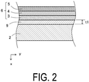
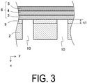
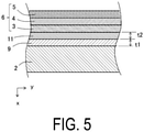
- FIGS. 2 and 3 are enlarged cross-sectional views of a portion surrounded by a dashed line in FIG. 1 .
- the metal plate 2 may be a flat plate-shaped porous body having an open porosity of, for example, 30% or more, particularly in a range of from 35% to 50%.
- the metal plate 2 may be a dense plate having a plurality of through holes 10 passing through the metal plate 2 in the thickness direction.
- Each of the through holes 10 may have, for example, a diameter of 0.01 mm or more and 1.0 mm or less in a cross-section perpendicular to the thickness direction of the metal plate 2.
- the dense metal plate 2 has a smaller surface area and higher corrosion resistance than the porous metal plate 2. Additionally, since the surface area of the dense metal plate 2 is small, an oxide film formed on the surface, that is, the content of the oxide is small. Therefore, the dense metal plate 2 has higher electrical conductivity.
- the shape of the metal plate 2 may be a flat plate having the first surface 2a and the second surface 2b, which are a pair of flat surfaces facing each other.
- the shape of the metal plate 2 may be a curved plate having the first surface 2a and the second surface 2b, which are a pair of curved surfaces facing each other.
- the thickness of the metal plate 2 may be, for example, 100 ⁇ m or more and 1 mm or less.
- the material of the metal plate 2 may be, for example, a conductive material such as a heat-resistant alloy.
- the metal plate 2 contains Cr and may contain, for example, from 4 atomic% to 30 atomic% chromium (Cr) with respect to the entire alloy.
- the Cr-containing alloy may be a nickel-chromium-based alloy, an iron-chromium-based alloy, or austenite-based, ferrite-based, or austenite-ferrite-based stainless steel. Additionally, the metal plate 2 may contain manganese (Mn) or aluminum (Al) as an element other than Cr.
- the metal plate 2 and the first electrode layer 3 are often bonded by thermal treatment in the air or in a nitrogen atmosphere. This is because when thermal treatment is performed in a reducing atmosphere or in a vacuum, the first electrode layer 3 or the second electrode layer 5 is likely to be sintered and is not easily made porous. During this thermal treatment, the surface of the alloy containing Cr is oxidized, and a passivation film of chromium(III) oxide (Cr 2 O 3 ) is formed on the surface of the alloy.
- the metal plate 2 has high corrosion resistance due to this passivation film. However, Cr 2 O 3 has low electrical conductivity and increases the electric resistance between the metal plate 2 and the first electrode layer 3 as the fuel electrode or the like.
- the cell 1 of the present disclosure has a first intermediate layer 9 containing chromium(III) oxide (Cr 2 O 3 ) and first conductive particles different from Cr 2 O 3 between the first surface 2a of the metal plate 2 and the first electrode layer 3.
- the first intermediate layer 9 has electrical conductivity.
- the first intermediate layer 9 may be a porous layer having an open porosity of, for example, 30% or more, in particular, in a range of from 35% to 50%.
- the first intermediate layer 9 may have a plurality of through holes 10 passing through the first intermediate layer 9 in the thickness direction.
- the first intermediate layer 9 having the plurality of through holes 10 may be a dense layer.
- the first intermediate layer 9 is sandwiched between the first surface 2a of the metal plate 2 and the first electrode layer 3. When the metal plate 2 has the plurality of through holes 10, the plurality of through holes 10 also pass through the first intermediate layer 9.
- An average thickness t1 of the first intermediate layer 9 may be, for example, 0.5 ⁇ m or more and 20 ⁇ m or less.
- the durability of the metal plate 2 can be enhanced even in a high temperature reaction atmosphere.
- Cr 2 O 3 is an insulator having an electrical resistivity of approximately 10 10 ⁇ •m
- the first intermediate layer 9 contains only Cr 2 O 3 , the electric resistance between the metal plate 2 and the first electrode layer 3 becomes high, and it becomes difficult for the metal plate 2 to collect the electricity generated in the element portion 6.
- the first intermediate layer 9 contains Cr 2 O 3 and further contains the first conductive particles different from Cr 2 O 3
- the conductivity of the first intermediate layer 9 becomes high, and the electricity generated in the element portion 6 can be easily collected by the metal plate 2 through the first conductive particles different from Cr 2 O 3 .
- the power generation efficiency of the cell 1 can be enhanced.
- the first conductive particles different from Cr 2 O 3 have an electrical resistivity of approximately 10 ⁇ •m or less.
- the particle size of the first conductive particles different from Cr 2 O 3 is smaller than the thickness t1 of the first intermediate layer 9.
- the particle size of the first conductive particles is, for example, less than 0.5 ⁇ m.
- the first conductive particles different from Cr 2 O 3 may be simply referred to as first conductive particles.
- Cr 2 O 3 tends to have a reduced electric resistance due to the other elements such as Ti and Mn in solid solution.
- electron transfer in Cr 2 O 3 basically occurs when electrons trapped in Cr atoms hop between atoms.
- the amount of electrons that transfer by hopping is much smaller than the amount of free electrons that flow through a metal or the like. Therefore, even when Cr 2 O 3 includes other elements in solid solution, the electrical conductivity is lower than that of a metal or the like.
- the electric resistance of Cr 2 O 3 fluctuates depending on the type and amount of element in solid solution, and the surrounding atmosphere, for example, the oxygen partial pressure, stable characteristics cannot be obtained.
- the first intermediate layer 9 of the present disclosure contains the first conductive particles different from Cr 2 O 3 .
- the electric resistance becomes smaller due to the conductivity of the first conductive particles themselves, and the contact between the first conductive particles forms a current path in the first intermediate layer 9, which facilitates the flow of current.
- the electric field strength applied to Cr 2 O 3 between the first conductive particles becomes large, thereby facilitating flow of the current. Therefore, when the first conductive particles are dispersed, the electric resistance of the first intermediate layer 9 as a whole becomes smaller and the electrical conductivity becomes higher than when Cr 2 O 3 includes other elements in solid solution.
- the electrical conductivity of the entirety of the first intermediate layer 9 can be further enhanced.
- Cr 2 O 3 may include other elements in solid solution, such as Ti and Mn described above, in the first intermediate layer 9.
- the first conductive particles may be surrounded by the first intermediate layer 9. That is, the first conductive particles may be inside the first intermediate layer 9 and need not be exposed outside the first intermediate layer 9.
- the first conductive particles are surrounded by the first intermediate layer 9, that is, Cr 2 O 3 in the first intermediate layer, for example, even when the conductivity of the first conductive particles fluctuates due to a change in the atmosphere with which the first conductive particles are in contact, the influence of the change in the atmosphere surrounding the first intermediate layer 9 on the first conductive particles becomes small. As a result, the electrical conductivity of the first conductive particles is less likely to fluctuate.
- the change in the surrounding atmosphere is, for example, the change in the concentration of the fuel gas in contact with the first intermediate layer 9.
- the cell in which the metal plate 2 and the first electrode layer 3 are directly bonded has a lower electric resistance between the metal plate 2 and the first electrode layer 3 than the cell 1 having the passivation layer, which is the oxide film, or the first intermediate layer 9 between the metal plate 2 and the first electrode layer 3.
- the metal plate 2 since the metal plate 2 does not have the passivation layer, there is a concern that the corrosion resistance may be lowered.
- the first intermediate layer 9 may contain, with respect to the total amount of the elements contained in the first intermediate layer 9 in terms of an oxide, for example, 50 mol% or more and 95 mol% or less of Cr 2 O 3 , and, for example, more than 5 mol% and less than 50 mol% of the first conductive particles in terms of an oxide. In addition, the first intermediate layer 9 may contain approximately 3 vol% or more and 40 vol% or less of the first conductive particles. A method for measuring the composition of the first intermediate layer 9 will be described later.
- the first intermediate layer 9 may contain at least one of manganese (Mn) and aluminum (Al) in addition to Cr 2 O 3 and the first conductive particles.
- Mn manganese
- Al aluminum
- Mn may be used to form MnCr 2 O 4 , which is a spinel crystal which is a composite oxide of Cr and Mn.
- Mn and Al may be contained in the metal plate 2.
- the first conductive particles may be, for example, metal or alloy particles, conductive oxide particles, or the like.
- the first conductive particles may contain metals such as Ni, Cu, Co, Fe, and Ti, or alloys thereof. Metals such as Ni, Cu, Co, Fe, and Ti or alloys thereof have an electrical resistivity of approximately 10 -6 ⁇ •m or less and have high conductivity.
- the first conductive particles may contain a lanthanum chromite-based perovskite oxide (LaCrO 3 -based oxide) or a lanthanum strontium titanium-based perovskite oxide (LaSrTiO 3 -based oxide).
- perovskite oxides have an electrical resistivity of approximately 10 ⁇ •m or less, and have electrical conductivity, and are neither reduced nor oxidized even when the perovskite oxides come into contact with a fuel gas such as a hydrogen-containing gas and an oxygen-containing gas such as air.
- a fuel gas such as a hydrogen-containing gas and an oxygen-containing gas such as air.
- These metals or alloys and perovskite oxides are stable even at a high temperature and have high electrical conductivity, so that the electricity generated in the element portion 6 can be easily collected by the metal plate 2.
- the metal Ni not only has high electrical conductivity, but its conductivity is unlikely to fluctuate due to a change in atmosphere. Therefore, the metal Ni can maintain high electrical conductivity even in a high temperature reaction atmosphere. Accordingly, the metal Ni can maintain stable electrical conductivity even when the surrounding atmosphere, for example, the concentration of the fuel gas fluctuates. Further, Ni is contained in the first electrode layer 3, which is the fuel electrode, and the first intermediate layer 9 contains the first conductive particles containing Ni, so that the joining properties between the first intermediate layer 9 and the first electrode layer 3 can be enhanced.
- the cell 1 may further include a second intermediate layer 11, that is porous, between the first intermediate layer 9 and the first electrode layer 3.
- the second intermediate layer 11 also has gas permeability and electrical conductivity.
- the second intermediate layer 11 may have an open porosity of, for example, 30% or more, in particular, in a range of from 35% to 50%.
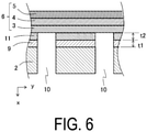
- the through holes 10 may pass through the second intermediate layer 11 in the thickness direction as illustrated in FIG. 6 , or need not pass through the second intermediate layer 11 as illustrated in FIG. 7 .
- the second intermediate layer 11 may be thicker than the first intermediate layer 9.
- a thickness t2 of the second intermediate layer 11 may be, for example, 10 ⁇ m or more and 200 ⁇ m or less. As illustrated in FIGS. 5 to 7 , the thickness t2 of the second intermediate layer 11 is the thickness of the second intermediate layer 11 located between the first intermediate layer 9 and the first electrode layer 3, and may be the distance between the first intermediate layer 9 and the first electrode layer 3.
- the thickness t2 of the second intermediate layer 11 is thicker than the thickness t1 of the first intermediate layer 9, Cr contained in the first intermediate layer 9 is less likely to diffuse into the first electrode layer 3.
- the second intermediate layer 11 When the second intermediate layer 11 has the above-mentioned open porosity, that is, an open porosity of 30% or more, the second intermediate layer 11 may fill at least a part of the through holes 10. That is, the thickness of the second intermediate layer 11 located above the through holes 10 illustrated in FIG. 7 may be larger than t2. The thickness of the second intermediate layer 11 located above the through holes 10 illustrated in FIG. 7 may be smaller than t2.
- the second intermediate layer 11 may contain second conductive particles.
- the second conductive particles contained in the second intermediate layer 11 may be the above-mentioned metal or alloy particles, conductive oxide particles, or the like.
- the material of the second conductive particles contained in the second intermediate layer 11 may be the same as or different from the first conductive particles contained in the first intermediate layer 9 described above.
- the second conductive particles contained in the second intermediate layer 11 may contain a metal element having electrical conductivity in a reduced state.
- the metal elements having electrical conductivity in the reduced state include, for example, Ni, Cu, Co, and Zn.
- the second intermediate layer 11 Since the second conductive particles contained in the second intermediate layer 11 contain a metal element having electrical conductivity in a reduced state, the second intermediate layer 11 can have high conductivity even in a reducing atmosphere, and the electricity generated in the element portion 6 can be easily collected by the metal plate 2.
- the first conductive particles contained in the first intermediate layer 9, that is porous may also contain a metal element having electrical conductivity in a reduced state.
- the first intermediate layer 9, that is dense may contain an oxide as the first conductive particles. Since the first intermediate layer 9, that is dense, has a small surface area, the first conductive particles, which are the oxide contained in the first intermediate layer 9 are less likely to be reduced under a reducing atmosphere.
- the second intermediate layer 11 may further contain an inorganic oxide.
- the inorganic oxide contained in the second intermediate layer 11 include oxides of Ti, Zr, Al, Si, Mg, Ca, Sr, and Ba, and rare earth oxides such as oxides of Y, Yb, Ce, and Gd.
- the inorganic oxide contained in the second intermediate layer 11 may be, for example, stabilized zirconia, a rare earth oxide, an ABO 3 perovskite oxide, or a titanium oxide. Note that an example of the rare earth oxide is yttrium oxide (Y 2 O 3 ).
- the second intermediate layer 11 may contain stabilized zirconia or a rare earth oxide contained in the fuel electrode.
- the second intermediate layer 11 may contain an electrically conductive ABO 3 perovskite oxide contained in the air electrode. Since the second intermediate layer 11 contains the same inorganic oxide as the inorganic oxide contained in the first electrode layer 3, the adhesive strength between the first electrode layer 3 and the metal plate 2 can be increased.
- the second intermediate layer 11 may contain at least one kind of inorganic oxide from among Ti, Al, and Si.
- the second intermediate layer 11 contains the inorganic oxides of Ti, Al, and Si, the components of the second conductive particles contained in the second intermediate layer 11 are likely to dissolve or diffuse in the first intermediate layer 9, and the ratio of the first conductive particles contained in the first intermediate layer 9 becomes larger, whereby the electrical conductivity of the first intermediate layer 9 can be made higher.
- the ratio of the second conductive particles may be, for example, 40 mol% or more and 80 mol% or less, and the ratio of the inorganic oxide may be, for example, more than 20 mol% and less than 60 mol%.
- the metal plate 2 may have recessed portions or projecting portions on at least one of the first surface 2a and the second surface 2b.
- FIG. 8 illustrates one example of the cell 1 provided with the metal plate 2 having recessed portions on the first surface 2a.
- a figure illustrated on the top side of FIG. 8 is a horizontal cross-sectional view of the cell 1, and a figure illustrated on the bottom side of FIG. 8 is a plan view of the first surface 2a of the metal plate 2.
- the metal plate 2 when the metal plate 2 has the recessed portions on the first surface 2a, the recessed portions need not be in contact with the first electrode layer 3. That is, the metal plate 2 may have gaps between the recessed portions of the first surface 2a and the first electrode layer 3.
- the gaps between the recessed portions of the first surface 2a and the first electrode layer 3 may be used as the gas-flow passages 7.
- the metal plate 2 also serves as the flow path member 8, so that the metal plate 2 need not have gas permeability between the first surface 2a and the second surface 2b.
- FIG. 9 illustrates one example of the cell 1 provided with the metal plate 2 having the projecting portions on the first surface 2a.
- a figure illustrated on the top side of FIG. 9 is a horizontal cross-sectional view of the cell 1, and a figure illustrated on the bottom side of FIG. 9 is a plan view of the first surface 2a of the metal plate 2.
- the cell 1 such as that described above has gaps between portions other than the projecting portions of the first surface 2a of the metal plate 2 and the first electrode layer 3, and these gaps may be used as the gas-flow passages 7.
- the metal plate 2 also serves as the flow path member 8, so that the metal plate 2 need not have gas permeability between the first surface 2a and the second surface 2b.
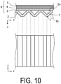
- the metal plate 2 may have recessed portions and projecting portions on both the first surface 2a and the second surface 2b.
- a figure illustrated on the top side of FIG. 10 is a horizontal cross-sectional view of the cell 1, and a figure illustrated on the bottom side of FIG. 10 is a plan view of the first surface 2a of the metal plate 2.
- the projecting portions of the first surface 2a of the metal plate 2 may be in contact with the first electrode layer 3.
- the cell 1 such as that described above has gaps between the recessed portions of the first surface 2a of the metal plate 2 and the first electrode layer 3, and these gaps may be used as the gas-flow passages 7.
- the metal plate 2 also serves as the flow path member 8, so that the metal plate 2 need not have gas permeability between the first surface 2a and the second surface 2b.
- the cells 1 illustrated in FIGS. 8 to 10 also include the above-mentioned first intermediate layer 9 between the first surface 2a and the first electrode layer 3.
- the cells 1 illustrated in FIGS. 8 to 10 may further include the second intermediate layer 11.
- the presence or absence of the first intermediate layer 9 and the second intermediate layer 11 can be confirmed, for example, by observing a cross section of the cell 1 with a scanning electron microscope (SEM), a scanning transmission electron microscope (STEM), a transmission electron microscope (TEM), or the like.
- SEM scanning electron microscope
- STEM scanning transmission electron microscope
- TEM transmission electron microscope
- the elements contained in the first intermediate layer 9 and the second intermediate layer 11 and the content ratios thereof can be analyzed with, for example, wavelength dispersive X-ray spectroscopy (WDS), energy dispersive X-ray spectroscopy (EDS), or an electron probe microanalyzer (EPMA). From the obtained elemental analysis results, the molar ratios of Cr 2 O 3 , the first or second conductive particles, and the inorganic oxide in terms of an oxide can be calculated. Further, as necessary, the first intermediate layer 9 or the second intermediate layer 11 may be cut out from the cell 1, and elemental analysis such as high-frequency inductively coupled plasma (ICP) emission spectros
- the volume ratio of the first conductive particles contained in the first intermediate layer 9 or the second conductive particles contained in the second intermediate layer 11 may be calculated based on the calculated molar ratios of Cr 2 O 3 , the first or second conductive particles, and the inorganic oxide.
- the volume ratio of the first conductive particles contained in the first intermediate layer 9 may be obtained, for example, by performing element mapping of a cross section of the first intermediate layer 9, calculating an area occupancy ratio of the elements contained in the first conductive particles by image analysis, and converting the area occupancy ratio into the volume ratio.
- the volume ratio of the second conductive particles contained in the second intermediate layer 11 may be obtained by image analysis of the element mapping image of the cross section of the second intermediate layer 11.
- a method of manufacturing the cell 1 provided with the first intermediate layer 9 when the first electrode layer 3 is used as the fuel electrode will be described.
- a base member such as stainless steel containing Cr is prepared.
- the base member may be an alloy plate or an alloy foil.
- the base member may be an alloy plate or an alloy foil having the through holes 10, or may be a porous sintered body made of a metal powder.
- a laminate formed of the fuel electrode and stabilized zirconia to be the solid electrolyte layer 4 is prepared.
- the fuel electrode contains Ni and/or NiO and stabilized zirconia.
- the laminate of the fuel electrode and the solid electrolyte layer 4 may be produced by the following method.
- a binder is added to a slurry obtained by mixing a Ni or NiO powder and a stabilized zirconia powder with an organic solvent to form a sheet, thereby obtaining a sheet compact for the fuel electrode.
- a binder is added to the slurry in which stabilized zirconia powder is mixed with an organic solvent, and sheet forming is performed on the sheet compact for the fuel electrode to obtain a laminated compact.
- the obtained laminated compact is fired to obtain the laminate of the fuel electrode and the solid electrolyte layer 4.
- the base member and the laminate of the fuel electrode, that is, the first electrode layer 3 and the solid electrolyte layer 4, are bonded with an adhesive.
- a paste is used containing at least one of the conductive particles of Ni, NiO, Cu, Co, and Zn, and as the inorganic oxide, at least one of oxides such as oxides of Ti, Zr, Al, Si, Mg, Ca, Sr, and Ba and rare earth oxides such as oxides of Y and Yb.
- the adhesive may contain not only one kind of conductive particles but also two or more kinds, and may contain not only one kind of inorganic oxide but also two or more kinds. Further, the inorganic oxide may be a composite oxide of two or more kinds of elements.
- the adhesive is applied to the first surface 2a of the base member, and the first surface 2a of the base member to which the adhesive has been applied is bonded to the surface of the first electrode layer 3 of the laminate.
- the bonded base member and the laminate are thermally treated in a nitrogen atmosphere or in the air, for example, in a range of from 1000°C to 1200°C for 0.5 hours to 2 hours.
- a Cr 2 O 3 film in which the first conductive particles such as Ni, Cu, Co, and Zn are dispersed is formed between the base member and the first electrode layer 3 after the thermal treatment.
- the oxides constituting the fuel electrode are reduced, and the particles of the material contained in the fuel electrode are likely to grow. As a result, sintering of the fuel electrode may proceed and it may be difficult for the fuel electrode and the fuel gas to react with each other, and the electric resistance of the fuel electrode may increase.
- the second intermediate layer 11 may be formed between the base member and the first electrode layer 3 depending on the kind of inorganic oxide contained in the adhesive, the coating thickness of the adhesive, the thermal treatment conditions, and the like. In some cases, the constituent components of the adhesive diffuse into the base member or the first electrode layer 3, and a clear second intermediate layer 11 is not formed. For example, when the coating thickness of the adhesive is 10 ⁇ m or more, or when the thermal treatment time is short, the constituent components of the adhesive do not diffuse into the base member or the first electrode layer 3 and easily remain at the interface, so that the second intermediate layer 11 is easily formed.
- the coating thickness of the adhesive is less than 1 ⁇ m, or when the thermal treatment time is long, most of the constituent components of the adhesive are diffused into the base member or the first electrode layer 3 and hardly remain at the interface, so that it is difficult to form the clear second intermediate layer 11.
- the adhesive contains titanium oxide (titania), the melting point of the adhesive is lowered, the adhesive is easily sintered, and the components of the conductive particles easily dissolve and diffuse in the first intermediate layer 9 and the first electrode layer 3. Further, Ti can form a solid solution with chromium oxide of the first intermediate layer 9 to make the first intermediate layer 9 more electrically conductive.
- titanium oxide titanium oxide
- the adhesive contains any of titania, aluminum oxide (alumina), and silicon oxide (silica)
- the coefficient of thermal expansion of the adhesive layer that is, the second intermediate layer 11 becomes small.
- the first electrode layer 3 is the fuel electrode
- the difference between the coefficient of thermal expansion of the second intermediate layer 11 and the coefficients of thermal expansion of the metal plate 2 and the first electrode layer 3 becomes small, so that the second intermediate layer 11 and the metal plate 2, and the second intermediate layer 11 and the first electrode layer 3 are less likely to be separated from each other.
- these inorganic oxides facilitate the transfer of the components of the conductive particles contained in the adhesive to the chromium oxide layer which is to be the first intermediate layer 9 on the surface of the base member.
- Ni/NiO, titanium oxide (titania), and yttrium oxide When the adhesive contains Ni/NiO, titanium oxide (titania), and yttrium oxide together, Ni/NiO and titanium oxide (titania) react with yttrium oxide to form a composite oxide such as Y 2 Ti 2 O 7 or Y 2 Ti 2 O 7 including NiO in solid solution.
- the crystal phase of this composite oxide is stable in a reducing atmosphere, the crystal structure is less likely to change due to the effect of the atmosphere, and breakage due to volume change associated with the phase transformation of the crystal is unlikely to occur.
- the cell 1 of the present disclosure can be obtained by forming an air electrode, which is the second electrode layer 5, on the surface of the solid electrolyte layer 4 of the base member and the laminate bonded with the adhesive.
- the air electrode may be obtained, for example, by adding a binder to the slurry obtained by mixing electrically conductive ABO 3 perovskite oxide powder with an organic solvent, printing on the surface of the solid electrolyte layer 4, and then firing at 1000°C to 1200°C in an oxidizing atmosphere together with the base member and the laminate.
- the laminate of the first electrode layer 3 and the solid electrolyte layer 4 is prepared in advance, and then the laminate is bonded to the substrate.
- the first electrode layer 3 and the solid electrolyte layer 4 may be sequentially formed on the metal plate 2 without preparing the laminate of the first electrode layer 3 and the solid electrolyte layer 4.
- a sheet compact to be the first electrode layer 3 may be adhered to the metal plate 2 to which the adhesive has been applied, and a sheet to be the solid electrolyte layer 4 may be further formed on the sheet compact, and then they may be fired.
- the solid electrolyte layer 4 may be formed on the surface of the fired first electrode layer 3 by, for example, a vacuum film formation method such as
- a cell stack device 20 includes a cell stack 21 in which a plurality of cells 1 are disposed and a gas tank 22. A lower end portion of the cell 1 is bonded to and fixed to an opening portion of the gas tank 22. The gas tank 22 supplies fuel gas to the plurality of cells 1.
- the cell stack 21 includes the plurality of cells 1 disposed or stacked in the thickness direction of the cell 1, and conductive members 23a that electrically connect adjacent ones of the cells 1 in series.
- Each of the cells 1 is the cell 1 including the first intermediate layer 9 described above.
- the direction in which the plurality of cells 1 are disposed is referred to as an arrangement direction x.
- the conductive members 23a may also be disposed on the two ends of the cell stack 21 in the arrangement direction x.
- the conductive members 23a may be bonded to the cells 1 with a conductive adhesive.
- an elastic metal or alloy may be used, or felt made of metal fiber or alloy fiber may be used.
- the felt made of metal fiber or alloy fiber may be surface-treated as needed.
- the cell stack device 20 includes end conductive members 23b outside the cell stack 21 in the arrangement direction x.
- the end conductive members 23b are electrically connected to the cells 1 located on the outermost sides in the arrangement direction x.
- Each of the end conductive members 23b includes a lead-out portion 23c that protrudes outward in the arrangement direction x.
- the lead-out portions 23c collect the electricity generated in the cells 1 and draw out the collected electricity to the outside.
- FIG. 12 is an enlarged horizontal cross-sectional view of a portion surrounded by a dashed line in FIG. 11 .
- the lower end portion of the cell 1 is fixed to the opening portion of the gas tank 22 with a sealing member S.
- the gas-flow passage 7 of the cell 1 leads to a fuel gas chamber (not illustrated) of the gas tank 22.
- a material of the sealing member S may be, for example, glass having excellent thermal resistance.
- the lower end portions of the conductive members 23a and the end conductive members 23b may be fixed to the gas tank 22 with the sealing member S.
- the end conductive members 23b may be integrated with the cell stack 21.
- FIG. 13 is an exterior perspective view illustrating one example of a module including a cell stack device.
- a module 30 includes a rectangular parallelepiped-shaped housing container 31 and the above-mentioned cell stack device 20 housed inside the housing container 31.
- a reformer 32 is disposed above the cell stack 21.
- the reformer 32 is connected to the gas tank 22 by a gas flow pipe 33.
- the reformer 32 reforms raw fuel such as natural gas or kerosene supplied via a raw fuel supply pipe 34 to produce fuel gas.
- the gas flow pipe 33 supplies the fuel gas reformed by the reformer 32 to the gas tank 22.
- the fuel gas is supplied from the gas tank 22 to the gas-flow passage 7 of the cell 1.
- FIG. 13 illustrates a state in which a front surface portion and a rear surface portion, which are parts of the housing container 31, are removed, and the cell stack device 20 housed inside the housing container 31 is taken out rearward.
- the cell stack device 20 can be slid and housed in the housing container 31.
- the cell stack device 20 need not include the reformer 32.
- the housing container 31 includes an oxygen-containing-gas inlet member 35 therein.
- the oxygen-containing-gas inlet member 35 in FIG. 13 is disposed between the two cell stacks 21 in a state in which the cell stack device 20 is housed in the housing container 31.
- the oxygen-containing-gas inlet member 35 supplies the oxygen-containing gas to the lower end portion of the cell 1.
- the oxygen-containing gas flows along the side of the cell 1 from the lower end portion to the upper end portion in synchronization with the flow of the fuel gas by the oxygen-containing-gas inlet member 35.
- the fuel gas discharged from the gas-flow passage 7 of the cell 1 to the upper end portion of the cell 1 is mixed with the oxygen-containing gas and burned.
- the temperature of the cell 1 rises, and the activation of the cell stack device 20 can be accelerated.
- the reformer 32 disposed above the cell 1 is heated, and the reformer 32 can efficiently perform a reformation reaction.
- FIG. 14 is an exploded perspective view illustrating one example of a module housing device. Note that some configurations are omitted in FIG. 14 .
- the module housing device includes an external case, a module housed in the external case, and an auxiliary device configured to operate the module and housed in the external case.
- a module housing device 40 illustrated in FIG. 14 has supports 41 and exterior plates 42.
- a dividing plate 43 divides the inside of the external case into upper and lower spaces.
- a space above the dividing plate 43 in the external case is a module housing chamber 44 that houses the module 30, and a space below the dividing plate 43 in the external case is an auxiliary device housing chamber 45 that houses the auxiliary device for operating the module 30. Note that the description of the auxiliary device to be housed in the auxiliary device housing chamber 45 is omitted.
- the dividing plate 43 has an air flow port 46 for allowing the air in the auxiliary device housing chamber 45 to flow into the module housing chamber 44.
- One of the exterior plates 42 forming the module housing chamber 44 has an exhaust hole 47 for exhausting the air in the module housing chamber 44. The air in the module housing chamber 44 is exhausted from the exhaust hole 47.
- the module housing device 40 can have high power generation efficiency.
- the present disclosure has been described in detail above. However, the present disclosure is not limited to the embodiments described above.
- the cell, the cell stack device, the module, and the module housing device of the present disclosure may be variously modified, improved, and the like without departing from the gist of the present disclosure.
- the fuel gas is supplied to the gas-flow passage 7 in the cell 1 and the oxygen-containing gas is supplied to the outside of the cell 1.
- the oxygen-containing gas may be supplied to the gas-flow passage 7, and the fuel gas may be supplied to the outside of the cell 1.
- the fuel cell, the fuel cell stack device, the fuel cell module, and the fuel cell device are respectively illustrated as one example of the “cell”, the “cell stack device”, the “module”, and the “module housing device”.
- the "cell”, the “cell stack device”, the “module”, and the “module housing device” may be an electrolysis cell, an electrolysis cell stack device, an electrolysis module, and an electrolysis device, respectively.
- a substrate having 81 through holes/cm 2 with a diameter of 0.3 mm formed on a stainless steel plate having a thickness of 0.3 mm containing Cr was prepared.
- a laminate of a fuel electrode, which is a mixture of NiO and stabilized zirconia, and a solid electrolyte layer made of stabilized zirconia was prepared.
- the fuel electrode contains 60% by mass of NiO and 40% by mass of stabilized zirconia.
- Stabilized zirconia contained in the fuel electrode and the solid electrolyte layer contains 8 mol% yttrium in the form of Y 2 O 3 .
- the laminate was fired in the air at a maximum temperature of 1400°C for two hours to become integrated.
- a material to which a TiO 2 powder and a Y 2 O 3 powder were added instead of stabilized zirconia contained in the fuel electrode that is, a material A containing NiO, TiO 2 , and Y 2 O 3 was prepared.
- the composition of the material A was 65% by mass of NiO, 10% by mass of TiO 2 , and 25% by mass of Y 2 O 3 .
- a paste of the material A was prepared and applied to the surface of the substrate which is stainless steel.
- the coating thickness of the adhesive was 50 ⁇ m. After the surface of the substrate coated with the adhesive and the surface of the fuel electrode of the laminate were bonded together, thermal treatment was performed in the air at a maximum temperature of 1050°C for two hours to bond the substrate and the fuel electrode to obtain a joint body.
- the electrical resistivity of the obtained joint body was measured as follows. LaSrCoO 3 was baked onto the solid electrolyte layer to obtain an electrode with a diameter of 10 mm. A platinum mesh was attached to the surface of the base member facing the electrode, that is, the surface having no power generation element, and used as a counter electrode. The electrical resistivity was measured by an AC four-terminal method.
- the electrical resistivity of the substrate that was thermally treated under the same conditions without applying the adhesive was measured. While the electrical resistivity of the comparative example was 7.06 ⁇ •m, the electrical resistivity of the entire intermediate layer including the first intermediate layer and the second intermediate layer of the joint body using the material A was 0.047 ⁇ •m.
- the cross-sections of the comparative example and the joint body using the material A were confirmed by a scanning electron microscope (SEM). Elemental analysis of the cross section of each sample was performed using energy dispersive X-ray spectroscopy (EDS). In the reflection electron image obtained by the SEM, a dense chromium oxide layer having a contrast different from that of metal was formed on the surface of the substrate of the comparative example, and no particles containing other elements, that is, the first conductive particles, were detected in the chromium oxide layer.
- SEM scanning electron microscope
- EDS energy dispersive X-ray spectroscopy
- Each of the joint body using the material A and the joint body using the material B had, between the base member and the fuel electrode, a first intermediate layer containing chromium oxide and the first conductive particles containing Ni, and a second intermediate layer containing the second conductive particles that were porous and contained Ni, and inorganic oxides such as zirconia, TiO 2 , and Y 2 O 3 .
- the first intermediate layer of the joint body using the material A had an average thickness of 6 ⁇ m, and contained 80 mol% of chromium oxide and 20 mol% of Ni and Ti in terms of an oxide in total.
- the second intermediate layer had an average thickness of 50 ⁇ m and an open porosity of 40%, and contained 30 mol% of Ti and Y in terms of an oxide in total, and 70 mol% of Ni in terms of an oxide.
Landscapes
- Chemical & Material Sciences (AREA)
- Life Sciences & Earth Sciences (AREA)
- Engineering & Computer Science (AREA)
- Manufacturing & Machinery (AREA)
- Sustainable Development (AREA)
- Sustainable Energy (AREA)
- Chemical Kinetics & Catalysis (AREA)
- Electrochemistry (AREA)
- General Chemical & Material Sciences (AREA)
- Fuel Cell (AREA)
- Composite Materials (AREA)
Applications Claiming Priority (2)
| Application Number | Priority Date | Filing Date | Title |
|---|---|---|---|
| JP2019083010 | 2019-04-24 | ||
| PCT/JP2020/017521 WO2020218431A1 (ja) | 2019-04-24 | 2020-04-23 | セル、セルスタック装置、モジュール及びモジュール収容装置 |
Publications (2)
| Publication Number | Publication Date |
|---|---|
| EP3961777A1 true EP3961777A1 (de) | 2022-03-02 |
| EP3961777A4 EP3961777A4 (de) | 2023-09-20 |
Family
ID=72942793
Family Applications (1)
| Application Number | Title | Priority Date | Filing Date |
|---|---|---|---|
| EP20794119.6A Pending EP3961777A4 (de) | 2019-04-24 | 2020-04-23 | Zelle, zellenstapelvorrichtung, modul und modulgehäuse |
Country Status (5)
| Country | Link |
|---|---|
| US (1) | US12237553B2 (de) |
| EP (1) | EP3961777A4 (de) |
| JP (2) | JP7250910B2 (de) |
| CN (1) | CN113711402B (de) |
| WO (1) | WO2020218431A1 (de) |
Families Citing this family (16)
| Publication number | Priority date | Publication date | Assignee | Title |
|---|---|---|---|---|
| JP7360276B2 (ja) * | 2019-08-30 | 2023-10-12 | 太陽誘電株式会社 | 固体酸化物型燃料電池およびその製造方法 |
| JP7377051B2 (ja) | 2019-10-07 | 2023-11-09 | 太陽誘電株式会社 | 固体酸化物型燃料電池およびその製造方法 |
| JP7484048B2 (ja) | 2020-03-10 | 2024-05-16 | 太陽誘電株式会社 | 固体酸化物型燃料電池およびその製造方法 |
| US20250192215A1 (en) * | 2022-03-18 | 2025-06-12 | Kyocera Corporation | Electrochemical cell, electrochemical cell device, module, and module housing device |
| JPWO2023195520A1 (de) * | 2022-04-08 | 2023-10-12 | ||
| US20250385278A1 (en) | 2022-06-30 | 2025-12-18 | Kyocera Corporation | Electrochemical cell, electrochemical cell device, module, and module housing device |
| CN119698707A (zh) * | 2022-08-31 | 2025-03-25 | 京瓷株式会社 | 电化学单电池装置、模块以及模块收容装置 |
| JP7543601B1 (ja) * | 2022-09-29 | 2024-09-02 | 京セラ株式会社 | 導電部材、電気化学セル装置、モジュールおよびモジュール収容装置 |
| JPWO2024117052A1 (de) * | 2022-11-30 | 2024-06-06 | ||
| EP4621891A4 (de) | 2022-12-27 | 2026-04-29 | Kyocera Corp | Elektrochemische zelle, elektrochemische zellenvorrichtung, modul und modulaufnahmevorrichtung |
| JPWO2024150829A1 (de) * | 2023-01-13 | 2024-07-18 | ||
| WO2025028530A1 (ja) * | 2023-07-31 | 2025-02-06 | 京セラ株式会社 | 電気化学セル、電気化学セル装置、モジュールおよびモジュール収容装置 |
| WO2025095015A1 (ja) * | 2023-10-30 | 2025-05-08 | 京セラ株式会社 | 電気化学セル、電気化学セル装置、モジュールおよびモジュール収容装置 |
| WO2025183102A1 (ja) * | 2024-02-29 | 2025-09-04 | 京セラ株式会社 | 流路部材、電気化学セル、電気化学セル装置、モジュールおよびモジュール収容装置 |
| WO2025244917A1 (en) * | 2024-05-20 | 2025-11-27 | Precision Combustion, Inc. | Porous metal substrate for metal-supported electrochemical cell |
| JP2026006757A (ja) * | 2024-07-01 | 2026-01-16 | 株式会社デンソー | 固体酸化物形電解セル |
Family Cites Families (18)
| Publication number | Priority date | Publication date | Assignee | Title |
|---|---|---|---|---|
| JPH10172590A (ja) | 1996-12-12 | 1998-06-26 | Fuji Electric Corp Res & Dev Ltd | 固体電解質型燃料電池 |
| US6123898A (en) * | 1997-03-18 | 2000-09-26 | Sumitomo Special Metals Co., Ltd. | Low heat expansion alloy |
| JP4511122B2 (ja) * | 2003-02-28 | 2010-07-28 | 京セラ株式会社 | 燃料電池セル |
| JP4593997B2 (ja) * | 2004-07-28 | 2010-12-08 | 京セラ株式会社 | 燃料電池セル用支持体及び燃料電池セル並びに燃料電池 |
| JP5098186B2 (ja) * | 2006-02-20 | 2012-12-12 | 大日本印刷株式会社 | 色素増感型太陽電池の製造方法および色素増感型太陽電池 |
| TWI335305B (en) * | 2007-01-05 | 2011-01-01 | Univ Nat Taiwan Science Tech | The metallic bipolar plate of solid oxide fuel cell with perovskite protective coating and method of manufacturing thereof |
| EP2495791B1 (de) * | 2009-10-28 | 2019-07-10 | Kyocera Corporation | Brennstoffzelle, brennstoffzellenstapel, brennstoffzellenmodul und brennstoffzellenvorrichtung |
| US20130004881A1 (en) | 2010-03-15 | 2013-01-03 | Nima Shaigan | Composite coatings for oxidation protection |
| JP5712518B2 (ja) | 2010-07-16 | 2015-05-07 | 日産自動車株式会社 | 導電部材の製造方法 |
| JP5572146B2 (ja) | 2011-03-22 | 2014-08-13 | 大阪瓦斯株式会社 | 保護膜形成方法、セル接続部材および固体酸化物形燃料電池用セル |
| EP3016190B1 (de) * | 2013-06-27 | 2018-08-01 | Kyocera Corporation | Zelle, zellstapel, und modul |
| JP6204822B2 (ja) | 2013-12-24 | 2017-09-27 | 日本特殊陶業株式会社 | 固体酸化物形燃料電池 |
| JP5989941B1 (ja) * | 2014-10-29 | 2016-09-07 | 京セラ株式会社 | セル、セルスタック装置、モジュールおよびモジュール収容装置 |
| JP2016115506A (ja) | 2014-12-15 | 2016-06-23 | 株式会社村田製作所 | メタルサポートsofc |
| JP6735568B2 (ja) | 2015-03-31 | 2020-08-05 | 大阪瓦斯株式会社 | セルスタックの製造方法 |
| JP6581836B2 (ja) | 2015-08-03 | 2019-09-25 | 本田技研工業株式会社 | メタルサポートセル |
| JP6749050B2 (ja) | 2015-12-18 | 2020-09-02 | 京セラ株式会社 | セルスタック装置、モジュールおよびモジュール収容装置 |
| JP6910170B2 (ja) | 2017-03-22 | 2021-07-28 | 大阪瓦斯株式会社 | 金属支持型電気化学素子用の電極層付基板、電気化学素子、電気化学モジュール、電気化学装置、エネルギーシステム、固体酸化物形燃料電池、および製造方法 |
-
2020
- 2020-04-23 JP JP2021516208A patent/JP7250910B2/ja active Active
- 2020-04-23 EP EP20794119.6A patent/EP3961777A4/de active Pending
- 2020-04-23 US US17/601,772 patent/US12237553B2/en active Active
- 2020-04-23 CN CN202080030493.7A patent/CN113711402B/zh active Active
- 2020-04-23 WO PCT/JP2020/017521 patent/WO2020218431A1/ja not_active Ceased
-
2023
- 2023-03-22 JP JP2023044959A patent/JP7645920B2/ja active Active
Also Published As
| Publication number | Publication date |
|---|---|
| JP7250910B2 (ja) | 2023-04-03 |
| CN113711402A (zh) | 2021-11-26 |
| US20220200033A1 (en) | 2022-06-23 |
| CN113711402B (zh) | 2024-10-29 |
| EP3961777A4 (de) | 2023-09-20 |
| JP7645920B2 (ja) | 2025-03-14 |
| US12237553B2 (en) | 2025-02-25 |
| WO2020218431A1 (ja) | 2020-10-29 |
| JP2023093447A (ja) | 2023-07-04 |
| JPWO2020218431A1 (de) | 2020-10-29 |
Similar Documents
| Publication | Publication Date | Title |
|---|---|---|
| US12237553B2 (en) | Cell, cell stack device, module, and module housing device | |
| EP2393148B1 (de) | Wärmebeständige legierung, legierungselement für brennstoffzelle, brennstoffzellenstapelelement, brennstoffzellenmodul und brennstoffzellenelement | |
| EP3960902B1 (de) | Zelle, zellenstapelvorrichtung, modul und modulaufnahmevorrichtung | |
| EP1334528B1 (de) | Brennstoffzellen | |
| KR101553270B1 (ko) | 고체 산화물형 연료 전지용 셀 | |
| TWI761479B (zh) | 電化學元件、電化學模組、電化學裝置、能源系統、固態氧化物型燃料電池、及電化學元件之製造方法 | |
| US8852825B2 (en) | Multi-layered coating providing corrosion resistance to zirconia based electrolytes | |
| EP2495791B1 (de) | Brennstoffzelle, brennstoffzellenstapel, brennstoffzellenmodul und brennstoffzellenvorrichtung | |
| EP3217457B1 (de) | Leitfähiges element, zellenstapelvorrichtung, modul und modulgehäusevorrichtung | |
| KR102564764B1 (ko) | 전기 화학 장치, 에너지 시스템, 및 고체 산화물형 연료 전지 | |
| JP5079991B2 (ja) | 燃料電池セル及び燃料電池 | |
| JP6818960B1 (ja) | セル、セルスタック装置、モジュールおよびモジュール収容装置 | |
| HK1054123B (en) | Fuel cells |
Legal Events
| Date | Code | Title | Description |
|---|---|---|---|
| STAA | Information on the status of an ep patent application or granted ep patent |
Free format text: STATUS: THE INTERNATIONAL PUBLICATION HAS BEEN MADE |
|
| PUAI | Public reference made under article 153(3) epc to a published international application that has entered the european phase |
Free format text: ORIGINAL CODE: 0009012 |
|
| STAA | Information on the status of an ep patent application or granted ep patent |
Free format text: STATUS: REQUEST FOR EXAMINATION WAS MADE |
|
| 17P | Request for examination filed |
Effective date: 20210927 |
|
| AK | Designated contracting states |
Kind code of ref document: A1 Designated state(s): AL AT BE BG CH CY CZ DE DK EE ES FI FR GB GR HR HU IE IS IT LI LT LU LV MC MK MT NL NO PL PT RO RS SE SI SK SM TR |
|
| DAV | Request for validation of the european patent (deleted) | ||
| DAX | Request for extension of the european patent (deleted) | ||
| P01 | Opt-out of the competence of the unified patent court (upc) registered |
Effective date: 20230508 |
|
| REG | Reference to a national code |
Ref country code: DE Ref legal event code: R079 Free format text: PREVIOUS MAIN CLASS: H01M0008120000 Ipc: H01M0008247500 |
|
| A4 | Supplementary search report drawn up and despatched |
Effective date: 20230823 |
|
| RIC1 | Information provided on ipc code assigned before grant |
Ipc: H01M 8/0206 20160101ALI20230817BHEP Ipc: H01M 8/247 20160101ALI20230817BHEP Ipc: H01M 8/0228 20160101ALI20230817BHEP Ipc: H01M 8/2475 20160101AFI20230817BHEP |