EP3961799A1 - Batterie - Google Patents
Batterie Download PDFInfo
- Publication number
- EP3961799A1 EP3961799A1 EP21192778.5A EP21192778A EP3961799A1 EP 3961799 A1 EP3961799 A1 EP 3961799A1 EP 21192778 A EP21192778 A EP 21192778A EP 3961799 A1 EP3961799 A1 EP 3961799A1
- Authority
- EP
- European Patent Office
- Prior art keywords
- tab
- core
- cover plate
- separator
- region
- Prior art date
- Legal status (The legal status is an assumption and is not a legal conclusion. Google has not performed a legal analysis and makes no representation as to the accuracy of the status listed.)
- Pending
Links
- 238000005452 bending Methods 0.000 claims abstract description 78
- 125000006850 spacer group Chemical group 0.000 claims description 24
- 230000007704 transition Effects 0.000 claims description 15
- 238000005476 soldering Methods 0.000 description 14
- 229910000679 solder Inorganic materials 0.000 description 6
- 238000010586 diagram Methods 0.000 description 4
- 238000004519 manufacturing process Methods 0.000 description 3
- HBBGRARXTFLTSG-UHFFFAOYSA-N Lithium ion Chemical group [Li+] HBBGRARXTFLTSG-UHFFFAOYSA-N 0.000 description 1
- 230000009286 beneficial effect Effects 0.000 description 1
- 238000005056 compaction Methods 0.000 description 1
- 230000003247 decreasing effect Effects 0.000 description 1
- 238000009434 installation Methods 0.000 description 1
- 229910001416 lithium ion Inorganic materials 0.000 description 1
- 238000000034 method Methods 0.000 description 1
- 238000012986 modification Methods 0.000 description 1
- 230000004048 modification Effects 0.000 description 1
- 238000003825 pressing Methods 0.000 description 1
- 230000008569 process Effects 0.000 description 1
Images

Classifications
-
- H—ELECTRICITY
- H01—ELECTRIC ELEMENTS
- H01M—PROCESSES OR MEANS, e.g. BATTERIES, FOR THE DIRECT CONVERSION OF CHEMICAL ENERGY INTO ELECTRICAL ENERGY
- H01M6/00—Primary cells; Manufacture thereof
-
- H—ELECTRICITY
- H01—ELECTRIC ELEMENTS
- H01M—PROCESSES OR MEANS, e.g. BATTERIES, FOR THE DIRECT CONVERSION OF CHEMICAL ENERGY INTO ELECTRICAL ENERGY
- H01M50/00—Constructional details or processes of manufacture of the non-active parts of electrochemical cells other than fuel cells, e.g. hybrid cells
- H01M50/50—Current conducting connections for cells or batteries
- H01M50/531—Electrode connections inside a battery casing
- H01M50/533—Electrode connections inside a battery casing characterised by the shape of the leads or tabs
-
- H—ELECTRICITY
- H01—ELECTRIC ELEMENTS
- H01M—PROCESSES OR MEANS, e.g. BATTERIES, FOR THE DIRECT CONVERSION OF CHEMICAL ENERGY INTO ELECTRICAL ENERGY
- H01M50/00—Constructional details or processes of manufacture of the non-active parts of electrochemical cells other than fuel cells, e.g. hybrid cells
- H01M50/50—Current conducting connections for cells or batteries
- H01M50/531—Electrode connections inside a battery casing
- H01M50/54—Connection of several leads or tabs of plate-like electrode stacks, e.g. electrode pole straps or bridges
-
- H—ELECTRICITY
- H01—ELECTRIC ELEMENTS
- H01M—PROCESSES OR MEANS, e.g. BATTERIES, FOR THE DIRECT CONVERSION OF CHEMICAL ENERGY INTO ELECTRICAL ENERGY
- H01M10/00—Secondary cells; Manufacture thereof
- H01M10/04—Construction or manufacture in general
- H01M10/0413—Large-sized flat cells or batteries for motive or stationary systems with plate-like electrodes
-
- H—ELECTRICITY
- H01—ELECTRIC ELEMENTS
- H01M—PROCESSES OR MEANS, e.g. BATTERIES, FOR THE DIRECT CONVERSION OF CHEMICAL ENERGY INTO ELECTRICAL ENERGY
- H01M10/00—Secondary cells; Manufacture thereof
- H01M10/04—Construction or manufacture in general
- H01M10/0436—Small-sized flat cells or batteries for portable equipment
-
- H—ELECTRICITY
- H01—ELECTRIC ELEMENTS
- H01M—PROCESSES OR MEANS, e.g. BATTERIES, FOR THE DIRECT CONVERSION OF CHEMICAL ENERGY INTO ELECTRICAL ENERGY
- H01M50/00—Constructional details or processes of manufacture of the non-active parts of electrochemical cells other than fuel cells, e.g. hybrid cells
- H01M50/10—Primary casings; Jackets or wrappings
- H01M50/102—Primary casings; Jackets or wrappings characterised by their shape or physical structure
- H01M50/103—Primary casings; Jackets or wrappings characterised by their shape or physical structure prismatic or rectangular
-
- H—ELECTRICITY
- H01—ELECTRIC ELEMENTS
- H01M—PROCESSES OR MEANS, e.g. BATTERIES, FOR THE DIRECT CONVERSION OF CHEMICAL ENERGY INTO ELECTRICAL ENERGY
- H01M50/00—Constructional details or processes of manufacture of the non-active parts of electrochemical cells other than fuel cells, e.g. hybrid cells
- H01M50/10—Primary casings; Jackets or wrappings
- H01M50/102—Primary casings; Jackets or wrappings characterised by their shape or physical structure
- H01M50/105—Pouches or flexible bags
-
- H—ELECTRICITY
- H01—ELECTRIC ELEMENTS
- H01M—PROCESSES OR MEANS, e.g. BATTERIES, FOR THE DIRECT CONVERSION OF CHEMICAL ENERGY INTO ELECTRICAL ENERGY
- H01M50/00—Constructional details or processes of manufacture of the non-active parts of electrochemical cells other than fuel cells, e.g. hybrid cells
- H01M50/10—Primary casings; Jackets or wrappings
- H01M50/102—Primary casings; Jackets or wrappings characterised by their shape or physical structure
- H01M50/107—Primary casings; Jackets or wrappings characterised by their shape or physical structure having curved cross-section, e.g. round or elliptic
-
- H—ELECTRICITY
- H01—ELECTRIC ELEMENTS
- H01M—PROCESSES OR MEANS, e.g. BATTERIES, FOR THE DIRECT CONVERSION OF CHEMICAL ENERGY INTO ELECTRICAL ENERGY
- H01M50/00—Constructional details or processes of manufacture of the non-active parts of electrochemical cells other than fuel cells, e.g. hybrid cells
- H01M50/10—Primary casings; Jackets or wrappings
- H01M50/172—Arrangements of electric connectors penetrating the casing
-
- H—ELECTRICITY
- H01—ELECTRIC ELEMENTS
- H01M—PROCESSES OR MEANS, e.g. BATTERIES, FOR THE DIRECT CONVERSION OF CHEMICAL ENERGY INTO ELECTRICAL ENERGY
- H01M50/00—Constructional details or processes of manufacture of the non-active parts of electrochemical cells other than fuel cells, e.g. hybrid cells
- H01M50/40—Separators; Membranes; Diaphragms; Spacing elements inside cells
- H01M50/471—Spacing elements inside cells other than separators, membranes or diaphragms; Manufacturing processes thereof
- H01M50/474—Spacing elements inside cells other than separators, membranes or diaphragms; Manufacturing processes thereof characterised by their position inside the cells
-
- H—ELECTRICITY
- H01—ELECTRIC ELEMENTS
- H01M—PROCESSES OR MEANS, e.g. BATTERIES, FOR THE DIRECT CONVERSION OF CHEMICAL ENERGY INTO ELECTRICAL ENERGY
- H01M50/00—Constructional details or processes of manufacture of the non-active parts of electrochemical cells other than fuel cells, e.g. hybrid cells
- H01M50/50—Current conducting connections for cells or batteries
- H01M50/531—Electrode connections inside a battery casing
- H01M50/538—Connection of several leads or tabs of wound or folded electrode stacks
-
- Y—GENERAL TAGGING OF NEW TECHNOLOGICAL DEVELOPMENTS; GENERAL TAGGING OF CROSS-SECTIONAL TECHNOLOGIES SPANNING OVER SEVERAL SECTIONS OF THE IPC; TECHNICAL SUBJECTS COVERED BY FORMER USPC CROSS-REFERENCE ART COLLECTIONS [XRACs] AND DIGESTS
- Y02—TECHNOLOGIES OR APPLICATIONS FOR MITIGATION OR ADAPTATION AGAINST CLIMATE CHANGE
- Y02E—REDUCTION OF GREENHOUSE GAS [GHG] EMISSIONS, RELATED TO ENERGY GENERATION, TRANSMISSION OR DISTRIBUTION
- Y02E60/00—Enabling technologies; Technologies with a potential or indirect contribution to GHG emissions mitigation
- Y02E60/10—Energy storage using batteries
-
- Y—GENERAL TAGGING OF NEW TECHNOLOGICAL DEVELOPMENTS; GENERAL TAGGING OF CROSS-SECTIONAL TECHNOLOGIES SPANNING OVER SEVERAL SECTIONS OF THE IPC; TECHNICAL SUBJECTS COVERED BY FORMER USPC CROSS-REFERENCE ART COLLECTIONS [XRACs] AND DIGESTS
- Y02—TECHNOLOGIES OR APPLICATIONS FOR MITIGATION OR ADAPTATION AGAINST CLIMATE CHANGE
- Y02P—CLIMATE CHANGE MITIGATION TECHNOLOGIES IN THE PRODUCTION OR PROCESSING OF GOODS
- Y02P70/00—Climate change mitigation technologies in the production process for final industrial or consumer products
- Y02P70/50—Manufacturing or production processes characterised by the final manufactured product
Definitions
- This application relates to the field of batteries, and in particular, to a secondary battery.
- a tab led out from the core bends to different degrees in the process of being connected to a cover plate.
- the root portion of the tab tilts to push down a separator.
- the tilting may even be so great that the root portion of the tab crosses the separator and comes into contact with an electrode plate, resulting in a short circuit in the secondary battery.
- the space design inside the casing of a battery has certain impact on the tab bending angle. If the space is excessively small, the tab is always in a pressed state in the small space, which cannot meet the requirements on the tab bending angle, resulting in a short circuit. If the bending space is excessively large, utilization of the height of the battery core is reduced, resulting in a decreased capacity of the battery core.
- this application provides a battery, including:
- the height of the tab bending space along the first direction is D g , and D g meets a relational expression: D * sin 45 ° ⁇ D g ⁇ D / 2 ⁇ tan 90 ° ⁇ a * D z ⁇ tan ⁇ , where D is the thickness of the core, Dz ranges from 1 mm to 2 mm, a is a tab bending angle, and ⁇ ranges from 10 degrees to 30 degrees.
- the tab bending angle ranges from 45 degrees to 135 degrees.
- the core includes a positive electrode plate, a negative electrode plate, and a separator disposed between the positive electrode plate and the negative electrode plate;
- a height of the tab bending region along the first direction ranges from 1 mm to 2 mm.
- a height of the separator is greater than a height of the negative electrode plate, and the height of the negative electrode plate is greater than a height of the positive electrode plate;
- the exposed separator and the tab are in parallel to each other in the separator extension region.
- the battery further includes an inner spacer and an outer spacer
- the plurality of tabs converge and form a tab convergence portion, and a tab protection sheet is provided outside the tab convergence portion; and a cover plate lead-out sheet is further disposed on the cover plate, and the tab protection sheet is connected to the cover plate lead-out sheet.
- a width of the tab protection sheet ranges from 8 mm to 12 mm.
- the design of the tab bending space in the casing of the battery in this application avoids a case that the tab is pressed to cause a short circuit due to an excessively small tab bending space and a case that the tab is pulled due to an excessively large tab bending space and utilization of the height of the battery core is reduced.
- the battery in this application has a reasonable space design, thereby ensuring that the tab bending angle is kept within a certain range to avoid a short circuit so as to improve the safety of the battery, and ensuring utilization of the height of the battery core to improve the battery core capacity.
- orientation or position relationships indicated by the terms such as “center”, “thickness”, “inner”, “outer”, “axial”, “radial”, and “circumferential” are based on orientation or position relationships shown in the accompanying drawings, and are used only for ease and brevity of illustration and description in this application, rather than indicating or implying that the mentioned apparatus or component needs to have a particular orientation or needs to be constructed and operated in a particular orientation. Therefore, such terms are not to be construed as limiting of this application.
- the battery 10 may be a secondary lithium ion battery or battery of another type.
- the battery 10 in the embodiments of this application includes: a casing 1, a cover plate 2, and a core 3.
- a cavity for accommodating the core 3 is provided in the casing 1, and the core 3 is disposed in the cavity in the casing 1.
- One end of the casing 1 is provided with an opening, and the cover plate 2 covers the opening of the casing 1.
- the core 3 is a laminated core or a wound core.
- a quantity of the cores 3 is not specifically limited, as long as the core can meet a requirement in practical installation or usage.
- the core 3 includes a positive electrode plate 31, a negative electrode plate 32, and a separator 33 disposed between the positive electrode plate and the negative electrode plate.
- an A-A line is a straight line at which an end portion of the positive electrode plate 31 is located;
- a B-B line is a straight line at which an end portion of the negative electrode plate 32 is located;
- a C-C line is a straight line at which an end portion of the separator 33 is located.
- a height of the separator 33 along a first direction is greater than a height of the negative electrode plate 32 along the first direction, and the height of the negative electrode plate 32 along the first direction is greater than a height of the positive electrode plate 31 along the first direction.
- the first direction is a height direction of the battery 10.
- a plurality of tabs 34 are disposed on the core 3, and the plurality of tabs 34 are connected to electrode plates in the core 3 respectively.
- the tabs 34 include positive tabs and negative tabs.
- the positive tabs are connected to the positive electrode plate, and the negative tabs are connected to the negative electrode plate.
- Ends of a plurality of positive tabs are connected to the positive electrode plate respectively, and the other ends of the plurality of positive tabs are connected to the cover plate after convergence.
- Ends of a plurality of negative tabs are connected to the negative electrode plate respectively, and the other ends of the plurality of negative tabs are connected to the cover plate after convergence.
- a tab bending space for accommodating the bent tab 34 is formed between the cover plate 2 and the core 3.
- the tab bending space includes a tab bending region 12 and a tab transition region 13.
- a D-D line is a dividing line between the tab bending region 12 and the tab transition region 13.
- a region between the D-D line and an E-E line is the tab transition region 13.
- apart of the separator 33 exceeding an end portion of the negative electrode plate 32 is an exposed separator, and a region in which the exposed separator is located forms a separator extension region 11.
- the separator extension region 11, the tab bending region 12, and the tab transition region 13 are distributed in sequence along the first direction.
- the tab transition region 13 is disposed between the tab bending region 12 and the cover plate 2, and the tab transition region 13 is arranged adjacent to the tab bending region 12.
- the bent tab 34 passes through the tab transition region 13 and is then fixedly connected to the cover plate 2.
- the first direction is the height direction of the battery 10.
- a height of the tab bending region 12 along the first direction ranges from 1 mm to 2 mm.
- the exposed separator is parallel to the tab, thereby avoiding a case that the tab pushes down the separator to cause a short circuit.
- the tab bending region 12 is located on an end portion of the separator 33.
- the tab 34 bends on the end portion of the separator 33 and forms a tab bending angle a.
- the tab bending angle a is located in the tab bending region 12. Specifically, the tab 34 bends at a junction of the separator extension region 11 and the tab bending region 12 and forms the tab bending angle a.
- the tab bending angle a ranges from 45 degrees to 135 degrees. Preferentially, the tab bending angle ranges from 60 degrees to 120 degrees.
- the design of the tab bending angle avoids a case that when the tabs bends, the positive and negative electrode plates and the separator press each other due to an excessively small tab bending angle to cause a short circuit of the battery.
- a cover plate lead-out sheet 21 is provided on an inner side surface of the cover plate 2.
- a tab bending space is formed between the cover plate lead-out sheet 21 and the core 3.
- the tab transition region 13 is disposed between the tab bending region 12 and the cover plate lead-out sheet 21.
- the inner side surface of the cover plate 2 refers to a side surface of the cover plate 2 opposite to the core 3.
- a tab protection sheet 35 is disposed at a junction of the plurality of tabs 34.
- a tab convergence portion formed by the plurality of tabs 34 after convergence is disposed between two tab protection sheets 35. The tab convergence portion is soldered to the tab protection sheet 35.
- the tab protection sheet 35 is soldered to the cover plate lead-out sheet 21 of the cover plate 2, so as to connect the tab 34 to the cover plate 2.
- a width of the tab protection sheet 35 is greater than or equal to 8 mm and less than or equal to 12 mm.
- the tab protection sheet 35 ensures that the tab is not ultrasonically cracked during soldering and avoids capacity loss.
- the width design of the tab protection sheet 35 further ensures that a sufficient soldering region is provided for subsequent laser soldering, and also ensures full compaction during laser soldering, thereby improving the reliability of laser soldering.
- the battery 10 has two cores 3, and the cover plate 2 has two cover plate lead-out sheets 21.
- the tabs 34 are bent to be parallel to the cover plate lead-out sheet 21 and are soldered to the cover plate lead-out sheet 21 respectively, so as to ensure reliable soldering of the cover plate lead-out sheet 21 and the tab protection sheet 35.
- a terminal 22 is disposed on the cover plate 2.
- the cover plate lead-out sheet 21 is connected to the terminal 22, and the tab protection sheet 35 is soldered to the cover plate lead-out sheet 21, so as to implement connection and current conduction.
- An insulating member 24 is further disposed between the inner side surface of the cover plate 2 and the cover plate lead-out sheet 21. The insulating member 24 insulates the cover plate 2 from positive and negative electrodes of the core, thereby preventing the positive and negative electrodes from coming into contact with the cover plate at the same time to cause a short circuit of the battery.
- a height of the tab bending space along the first direction is greater than D/10 and less than 3D/4.
- D is the thickness of the core.
- the height of the tab bending space along the first direction is D g , and D g meets a relational expression: D ⁇ sin 45° ⁇ D g ⁇ [D/2-(tan(90°-a) ⁇ D z )] ⁇ tan ⁇ , where D is the thickness of the core, ⁇ ranges from 10° to 30°, that is, ⁇ ranges from 10 degrees to 30 degrees, D z ranges from 1 mm to 2 mm, a is the tab bending angle, and 45° ⁇ a ⁇ 135°, that is a ranges from 45 degrees to 135 degrees.
- the tab bending space can be kept within a reasonable range, so as to prevent the tab from being pressed to cause a short circuit, and improve the utilization of the height of the battery core and the battery core capacity.
- the battery 10 in the embodiments of this application further includes an inner spacer 4 and an outer spacer 5. Both the inner spacer 4 and the outer spacer 5 are fixedly connected to the cover plate 2. The inner spacer 4 and the outer spacer 5 may alternatively be connected to the cover plate 2 in a fastening manner.
- the inner spacer 4 is disposed on the inner side surface of the cover plate 2, and a distance between a lower end surface of the inner spacer 4 and an upper end surface of the core 3 ranges from 0 mm to 1 mm. By setting the distance, the bending space may be further limited and supported while preventing the core 3 from moving in the first direction.
- the outer spacer 5 is disposed on the inner side surface of the cover plate 2 and is disposed perpendicular to the first direction.
- the core 3 may be prevented from swaying along a second direction.
- the second direction is perpendicular to the first direction.
- the second direction is a width or length direction of the battery 10.
- FIG. 2 is a schematic diagram of tabs of a core of a battery that do not bend or that are spread after convergence according to an embodiment of this application.
- a plurality of tabs 34 of a core 3 form a tab end-portion staggered layer region 341, a tab soldering region 342, and a pre-soldered press-fit region 343 in sequence after convergence.
- a width of the tab end-portion staggered layer region 341 is d 1 .
- a tab protection sheet 35 is disposed in the tab soldering region 342.
- a width of the tab protection sheet 35 is d 2
- a width direction of the tab protection sheet 35 is a left-right direction in FIG. 2 .
- a width of the pre-soldered press-fit region 343 is d 3 .
- a thickness of the core 3 is D, and a length of the tab exposed out of the core 3 is determined according to the width of the tab end-portion staggered layer region 341, the width of the tab soldering region 342, the width of the pre-soldered press-fit region 343, the thickness of the core 3, and a tab bending angle a of the tab 34.
- the width of the tab end-portion staggered layer region 341 is suitable, and the width of the tab end-portion staggered layer region 341 may be prevented from being too large, so that the length of the tab exposed out of the core 3 may be more suitable.
- 8 mm ⁇ d 2 ⁇ 12 mm, and preferentially, d 2 is 10 mm.
- the width of the tab protection sheet 35 is suitable, and a soldering width of the tab soldering region 342 may be ensured, so that the length of the tab exposed out of the core 3 may be more suitable, which is more conductive to production and manufacturing of the core 3.
- 0.5 mm ⁇ d 3 ⁇ 2 mm, and preferentially, d 3 is 1.5 mm.
- a width of the pre-soldered press-fit region 343 can be suitable, and a pre-soldering pressing block may press against the plurality of tabs 34, thereby ensuring the soldering quality of the plurality of tabs 34 and further ensuring the production quality of the core 3.
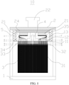
- FIG. 3 is a schematic diagram of a core of a battery connected to a cover plate in parallel before convergence or when being spread according to an embodiment of this application.
- a plurality of tabs 34 are soldered to a cover plate 2 of a battery 10 after convergence and a solder joint 23 is formed.
- a distance between a core 3 and the solder joint 23 is determined according to a thickness of the core 3, a tab bending angle a of the tab 34, and a width of a tab protection sheet 35.
- a distance from an end portion of a separator 33 of the core 3 opposite to the solder joint 23 to a center-point position of the solder joint 23 is L 1 . In this way, the tab 34 can be prevented from being pulled after bending and may further be prevented from being torn. In addition, a length that the tab 34 can move is more suitable to prevent the tab 34 from being pressed, thereby improving the safety of the battery 10 in use.
Landscapes
- Chemical & Material Sciences (AREA)
- Chemical Kinetics & Catalysis (AREA)
- Electrochemistry (AREA)
- General Chemical & Material Sciences (AREA)
- Engineering & Computer Science (AREA)
- Manufacturing & Machinery (AREA)
- Connection Of Batteries Or Terminals (AREA)
- Cell Separators (AREA)
Applications Claiming Priority (1)
| Application Number | Priority Date | Filing Date | Title |
|---|---|---|---|
| CN202010899177.5A CN114204224B (zh) | 2020-08-31 | 2020-08-31 | 一种电池 |
Publications (1)
| Publication Number | Publication Date |
|---|---|
| EP3961799A1 true EP3961799A1 (de) | 2022-03-02 |
Family
ID=77465876
Family Applications (1)
| Application Number | Title | Priority Date | Filing Date |
|---|---|---|---|
| EP21192778.5A Pending EP3961799A1 (de) | 2020-08-31 | 2021-08-24 | Batterie |
Country Status (6)
| Country | Link |
|---|---|
| US (1) | US20230207982A1 (de) |
| EP (1) | EP3961799A1 (de) |
| JP (1) | JP7703646B2 (de) |
| KR (1) | KR20230049687A (de) |
| CN (1) | CN114204224B (de) |
| WO (1) | WO2022042495A1 (de) |
Cited By (1)
| Publication number | Priority date | Publication date | Assignee | Title |
|---|---|---|---|---|
| EP4447176A3 (de) * | 2023-04-14 | 2025-01-22 | Volkswagen Ag | Batteriezelle mit einer elektrodenableiter-isolierung |
Families Citing this family (6)
| Publication number | Priority date | Publication date | Assignee | Title |
|---|---|---|---|---|
| DE102016016074A1 (de) | 2016-04-19 | 2024-05-23 | Jochen Karsch | Kaminaufsatz für einen Rauchgas- oder Lüftungsabzug |
| CN217933996U (zh) * | 2022-07-08 | 2022-11-29 | 厦门海辰储能科技股份有限公司 | 电池 |
| CN118738701A (zh) * | 2023-03-31 | 2024-10-01 | 宁德时代新能源科技股份有限公司 | 电池单体、电池及用电装置 |
| CN116213500B (zh) * | 2023-05-09 | 2023-08-04 | 宁德时代新能源科技股份有限公司 | 极耳整形装置、极耳整形方法及电池生产装置 |
| CN119542695B (zh) * | 2023-08-31 | 2025-10-17 | 比亚迪股份有限公司 | 电池单体、电池装置和用电设备 |
| CN119994408A (zh) * | 2025-03-07 | 2025-05-13 | 蜂巢能源科技股份有限公司 | 单体电池及电池包 |
Citations (4)
| Publication number | Priority date | Publication date | Assignee | Title |
|---|---|---|---|---|
| US20190221877A1 (en) * | 2018-01-12 | 2019-07-18 | Contemporary Amperex Technology Co., Limited | Secondary Battery and Vehicle |
| US20190363401A1 (en) * | 2017-02-22 | 2019-11-28 | Samsung Sdi Co., Ltd. | Secondary battery having symmetric multi-tabs |
| CN210897462U (zh) * | 2019-11-21 | 2020-06-30 | 四川新敏雅电池科技有限公司 | 锂离子电池封装结构 |
| US20200251711A1 (en) * | 2017-02-27 | 2020-08-06 | Sanyo Electric Co., Ltd. | Rectangular secondary battery and method of manufacturing the same |
Family Cites Families (11)
| Publication number | Priority date | Publication date | Assignee | Title |
|---|---|---|---|---|
| EP2866279B1 (de) * | 2012-06-26 | 2017-08-23 | Kabushiki Kaisha Toyota Jidoshokki | Akkumulatorvorrichtung |
| WO2014027606A1 (ja) * | 2012-08-14 | 2014-02-20 | 株式会社 豊田自動織機 | 蓄電装置 |
| CN104409768B (zh) * | 2014-11-25 | 2017-03-08 | 东莞新能源科技有限公司 | 锂电池 |
| JP2016110948A (ja) * | 2014-12-10 | 2016-06-20 | 株式会社豊田自動織機 | リチウムイオン二次電池 |
| CN106972144B (zh) * | 2016-01-14 | 2023-03-17 | 宁德时代新能源科技股份有限公司 | 二次电池 |
| KR102234993B1 (ko) * | 2016-12-21 | 2021-04-01 | 주식회사 엘지화학 | 전지셀 및 이의 제조방법 |
| CN206250267U (zh) * | 2016-12-27 | 2017-06-13 | 宁德时代新能源科技股份有限公司 | 电芯以及二次电池 |
| JP6930140B2 (ja) * | 2017-03-06 | 2021-09-01 | 株式会社村田製作所 | 二次電池 |
| JP2018156724A (ja) * | 2017-03-15 | 2018-10-04 | 日立化成株式会社 | リチウムイオン二次電池 |
| JP2020013752A (ja) * | 2018-07-20 | 2020-01-23 | 株式会社豊田自動織機 | 蓄電装置 |
| JP7300266B2 (ja) * | 2018-12-27 | 2023-06-29 | 三洋電機株式会社 | 二次電池 |
-
2020
- 2020-08-31 CN CN202010899177.5A patent/CN114204224B/zh active Active
-
2021
- 2021-08-23 JP JP2023513943A patent/JP7703646B2/ja active Active
- 2021-08-23 WO PCT/CN2021/114106 patent/WO2022042495A1/zh not_active Ceased
- 2021-08-23 KR KR1020237008084A patent/KR20230049687A/ko not_active Ceased
- 2021-08-24 EP EP21192778.5A patent/EP3961799A1/de active Pending
-
2023
- 2023-02-28 US US18/115,212 patent/US20230207982A1/en active Pending
Patent Citations (4)
| Publication number | Priority date | Publication date | Assignee | Title |
|---|---|---|---|---|
| US20190363401A1 (en) * | 2017-02-22 | 2019-11-28 | Samsung Sdi Co., Ltd. | Secondary battery having symmetric multi-tabs |
| US20200251711A1 (en) * | 2017-02-27 | 2020-08-06 | Sanyo Electric Co., Ltd. | Rectangular secondary battery and method of manufacturing the same |
| US20190221877A1 (en) * | 2018-01-12 | 2019-07-18 | Contemporary Amperex Technology Co., Limited | Secondary Battery and Vehicle |
| CN210897462U (zh) * | 2019-11-21 | 2020-06-30 | 四川新敏雅电池科技有限公司 | 锂离子电池封装结构 |
Cited By (1)
| Publication number | Priority date | Publication date | Assignee | Title |
|---|---|---|---|---|
| EP4447176A3 (de) * | 2023-04-14 | 2025-01-22 | Volkswagen Ag | Batteriezelle mit einer elektrodenableiter-isolierung |
Also Published As
| Publication number | Publication date |
|---|---|
| JP7703646B2 (ja) | 2025-07-07 |
| KR20230049687A (ko) | 2023-04-13 |
| JP2023539657A (ja) | 2023-09-15 |
| CN114204224A (zh) | 2022-03-18 |
| US20230207982A1 (en) | 2023-06-29 |
| WO2022042495A1 (zh) | 2022-03-03 |
| CN114204224B (zh) | 2023-06-13 |
Similar Documents
| Publication | Publication Date | Title |
|---|---|---|
| EP3961799A1 (de) | Batterie | |
| EP1724855B1 (de) | Deformierbarer Kern für eine cylindrische Lithium Batterie | |
| EP3852165B1 (de) | Sekundärbatterie und herstellungsverfahren für sekundärbatterie | |
| EP3745523B1 (de) | Sekundärbatterie und kraftfahrzeug | |
| CN111755657B (zh) | 电极组件 | |
| EP3961798A1 (de) | Batteriekern, batterie und batteriepack | |
| US9991499B2 (en) | Battery | |
| CN209401724U (zh) | 二次电池及电池模组 | |
| JP2009532824A (ja) | 改善された安全性を有する二次電池 | |
| WO2025035870A1 (zh) | 电池单体、电池单体的装配方法及电池包 | |
| EP4164021A1 (de) | Knopfbatteriezellenstruktur und herstellungsverfahren dafür sowie knopfbatterie | |
| US10505173B2 (en) | Connector having a narrow transition part disposed between two adjacent winding electrode cores of battery, and battery comprising the same | |
| JP2000200595A (ja) | 封口電池 | |
| US8043737B2 (en) | Secondary battery and method with electrode tap positioned at short side portion of secondary battery can | |
| CN217655970U (zh) | 电池盖板组件及动力电池 | |
| CN217589350U (zh) | 电池 | |
| CN116235362A (zh) | 具有用于短路防止的涂覆部的电极组件 | |
| KR20030066172A (ko) | 전극 탭 및 이를 구비한 밀폐전지 | |
| WO2025209475A1 (zh) | 导电柱、盖板组件、电池、电池装置及用电设备 | |
| US20230104632A1 (en) | Non-aqueous electrolyte secondary battery | |
| KR102960346B1 (ko) | 셀, 배터리, 및 배터리 팩 | |
| CN208225930U (zh) | 顶盖组件以及二次电池 | |
| JP7840393B2 (ja) | 二次電池 | |
| CN219717201U (zh) | 电池的转接片、顶盖组件、电芯和电池包 | |
| CN218005188U (zh) | 裸电芯、锂电池和车辆 |
Legal Events
| Date | Code | Title | Description |
|---|---|---|---|
| PUAI | Public reference made under article 153(3) epc to a published international application that has entered the european phase |
Free format text: ORIGINAL CODE: 0009012 |
|
| STAA | Information on the status of an ep patent application or granted ep patent |
Free format text: STATUS: REQUEST FOR EXAMINATION WAS MADE |
|
| 17P | Request for examination filed |
Effective date: 20210824 |
|
| AK | Designated contracting states |
Kind code of ref document: A1 Designated state(s): AL AT BE BG CH CY CZ DE DK EE ES FI FR GB GR HR HU IE IS IT LI LT LU LV MC MK MT NL NO PL PT RO RS SE SI SK SM TR |