EP3962007B1 - Procédé et appareil de traitement de symboles - Google Patents
Procédé et appareil de traitement de symboles Download PDFInfo
- Publication number
- EP3962007B1 EP3962007B1 EP20835505.7A EP20835505A EP3962007B1 EP 3962007 B1 EP3962007 B1 EP 3962007B1 EP 20835505 A EP20835505 A EP 20835505A EP 3962007 B1 EP3962007 B1 EP 3962007B1
- Authority
- EP
- European Patent Office
- Prior art keywords
- transmitted symbol
- symbol
- transmitted
- reference point
- time domain
- Prior art date
- Legal status (The legal status is an assumption and is not a legal conclusion. Google has not performed a legal analysis and makes no representation as to the accuracy of the status listed.)
- Active
Links
Images


Classifications
-
- H—ELECTRICITY
- H04—ELECTRIC COMMUNICATION TECHNIQUE
- H04L—TRANSMISSION OF DIGITAL INFORMATION, e.g. TELEGRAPHIC COMMUNICATION
- H04L27/00—Modulated-carrier systems
- H04L27/26—Systems using multi-frequency codes
- H04L27/2601—Multicarrier modulation systems
- H04L27/2602—Signal structure
-
- H—ELECTRICITY
- H04—ELECTRIC COMMUNICATION TECHNIQUE
- H04L—TRANSMISSION OF DIGITAL INFORMATION, e.g. TELEGRAPHIC COMMUNICATION
- H04L27/00—Modulated-carrier systems
- H04L27/26—Systems using multi-frequency codes
- H04L27/2601—Multicarrier modulation systems
- H04L27/2602—Signal structure
- H04L27/2605—Symbol extensions, e.g. Zero Tail, Unique Word [UW]
- H04L27/2607—Cyclic extensions
-
- H—ELECTRICITY
- H04—ELECTRIC COMMUNICATION TECHNIQUE
- H04L—TRANSMISSION OF DIGITAL INFORMATION, e.g. TELEGRAPHIC COMMUNICATION
- H04L27/00—Modulated-carrier systems
- H04L27/26—Systems using multi-frequency codes
- H04L27/2601—Multicarrier modulation systems
- H04L27/2602—Signal structure
- H04L27/261—Details of reference signals
- H04L27/2613—Structure of the reference signals
-
- H—ELECTRICITY
- H04—ELECTRIC COMMUNICATION TECHNIQUE
- H04L—TRANSMISSION OF DIGITAL INFORMATION, e.g. TELEGRAPHIC COMMUNICATION
- H04L5/00—Arrangements affording multiple use of the transmission path
- H04L5/003—Arrangements for allocating sub-channels of the transmission path
- H04L5/0048—Allocation of pilot signals, i.e. of signals known to the receiver
-
- H—ELECTRICITY
- H04—ELECTRIC COMMUNICATION TECHNIQUE
- H04L—TRANSMISSION OF DIGITAL INFORMATION, e.g. TELEGRAPHIC COMMUNICATION
- H04L5/00—Arrangements affording multiple use of the transmission path
- H04L5/003—Arrangements for allocating sub-channels of the transmission path
- H04L5/0078—Timing of allocation
-
- H—ELECTRICITY
- H04—ELECTRIC COMMUNICATION TECHNIQUE
- H04L—TRANSMISSION OF DIGITAL INFORMATION, e.g. TELEGRAPHIC COMMUNICATION
- H04L25/00—Baseband systems
- H04L25/02—Details ; arrangements for supplying electrical power along data transmission lines
- H04L25/03—Shaping networks in transmitter or receiver, e.g. adaptive shaping networks
- H04L25/03006—Arrangements for removing intersymbol interference
- H04L2025/03777—Arrangements for removing intersymbol interference characterised by the signalling
- H04L2025/03783—Details of reference signals
- H04L2025/03796—Location of reference signals
-
- H—ELECTRICITY
- H04—ELECTRIC COMMUNICATION TECHNIQUE
- H04L—TRANSMISSION OF DIGITAL INFORMATION, e.g. TELEGRAPHIC COMMUNICATION
- H04L25/00—Baseband systems
- H04L25/02—Details ; arrangements for supplying electrical power along data transmission lines
- H04L25/03—Shaping networks in transmitter or receiver, e.g. adaptive shaping networks
- H04L25/03006—Arrangements for removing intersymbol interference
- H04L25/03159—Arrangements for removing intersymbol interference operating in the frequency domain
Definitions
- This application relates to the communication field, and specifically, to a symbol processing method, a communication apparatus, a computer-readable storage medium and a program product.
- the guard interval can remove intersymbol interference (ISI) between adjacent symbols.
- ISI intersymbol interference
- the guard interval converts a linear convolution of the channel and the transmitted symbol into a cyclic convolution of the channel and the transmitted symbol, so that a symbol receive end can eliminate the multipath effect of the channel by using a frequency domain equalization method.
- a cyclic prefix (CP) is used as a guard interval between symbols.
- the CP is a cyclic structure formed by copying a segment of data at the end (or referred to as a tail) of a data symbol to the start (or referred to as a header) of the symbol.
- a stable frame structure needs to be maintained.
- a CP length is fixed.
- a network device configures a same CP length for a plurality of users.
- channel conditions are different for different users, and therefore requirements for a CP length may also be different.
- a system selects a CP whose length is greater than a multipath delay of a user with large delay spreading.
- an excessive CP causes unnecessary overheads.
- WO 2008/056901 A1 discloses a technology for extending a guard interval for individual user equipment in an OFDMA system.
- US 2011/0305286 A1 discloses that in a transmission apparatus which multicarrier-modulates and transmits symbols, which are basic units of digital signals, a subcarrier in which a symbol is arranged in a first multicarrier symbol having a first guard interval and a subcarrier in which a symbol is arranged in a second multicarrier symbol having a second guard interval longer than the first guard interval are scattered among a plurality of subcarriers constituting a multicarrier at the same time.
- US 2007/0165728 A1 discloses that a base station generates and transmits a multi-symbol beacon/timing synchronization signal.
- the multi-symbol beacon/timing synchronization signal includes: (i) an initial symbol including a body portion and a cyclic prefix, the cyclic prefix preceding the body portion and being generated from an end portion of the body portion and (ii) an extension symbol, which immediately follows the initial symbol.
- US 2017/0339697 A1 discloses a guard band signal for communication on a guard band between a first frequency band utilized by a first radio access technology having a first sub-carrier spacing and a second frequency band utilized by a second radio access technology having a second sub-carrier spacing that is a multiple of the first sub-carrier spacing.
- This application provides a symbol processing method, a communication apparatus, a computer-readable storage medium and a program product, as defined in the appended set of claims, to flexibly configure a guard interval between symbols when a CP length is fixed.
- the invention is defined by the independent claims and preferred embodiments are given by the dependent claims.
- a guard interval between symbols can be flexibly configured, and integrity of a reference signal can also be ensured.
- a guard interval between symbols can be flexibly configured, and a length of the guard interval can also be flexibly configured based on a user requirement.
- a single-carrier waveform such as DFT-s-OFDM or SC-QAM has a lower peak to average power ratio (PAPR). Therefore, in a case of a same power amplifier, the single-carrier waveform can provide larger output power and higher power amplification efficiency, and this improves coverage and reducing energy consumption. Therefore, single-carrier waveforms such as DFT-s-OFDM or SC-QAM are widely applied to various communication systems such as a long term evolution (LTE) system, a 5th generation (5G) system, or a new radio (NR) system.
- LTE long term evolution
- 5G 5th generation
- NR new radio
- DFT-s-OFDM is discrete fourier transform-spread-orthogonal frequency division multiplexing (DFT-s-OFDM).
- SC-QAM is single carrier-quadrature amplitude modulation (SC-QAM).
- the DFT-s-OFDM waveform uses a CP as a guard interval between symbols (DFT-s-OFDM symbols).
- FIG. 1 is a schematic diagram of a time domain structure in which a CP is used as a guard interval between symbols.
- two transmitted symbols are provided: a transmitted symbol 1 and a transmitted symbol 2.
- a CP of the transmitted symbol 1 refers to a cyclic structure formed by copying a segment of transmitted symbol components between a location from which a CP is obtained through truncation and an end location in the transmitted symbol 1 to the start of the transmitted symbol 1.
- a CP of the transmitted symbol 2 refers to a cyclic structure formed by copying a segment of transmitted symbol components between a location from which a CP is obtained through truncation and an end location in the transmitted symbol 2 to the start of the transmitted symbol 2.
- the CP of the transmitted symbol 2 is used as a guard interval between the transmitted symbol 1 and the transmitted symbol 2
- the CP of the transmitted symbol 1 is used as a guard interval between the transmitted symbol 1 and a transmitted symbol (not shown in FIG. 1 ) preceding the transmitted symbol 1.
- FIG. 2 shows receiving cases, at a receive end, of the transmitted symbol 1 and the transmitted symbol 2 shown in FIG. 1 after the transmitted symbol 1 and the transmitted symbol 2 are transmitted through a channel ( FIG. 2 shows only a maximum multipath delay of the channel as an example).
- Case 1 indicates that the maximum multipath delay of the channel does not exceed a CP length.
- a receive window of none of transmitted symbols includes ISI of another transmitted symbol.
- a receive window of the transmitted symbol 2 does not include the transmitted symbol 1, and therefore ISI of the transmitted symbol 1 can be avoided, and a receive window of the transmitted symbol 1 does not include the transmitted symbol (not shown in FIG. 2 ) preceding the transmitted symbol 1, and therefore the transmitted symbol 1 is not subject to ISI, either.
- a received symbol is a cyclic convolution of the transmitted symbol and the channel, so that the receive end can eliminate a multipath effect of the channel by using a frequency domain equalization method.
- Case 2 indicates that the maximum multipath delay of the channel exceeds a CP length.
- a receive window of one transmitted symbol includes another transmitted symbol.
- a receive window of the transmitted symbol 2 includes a segment of transmitted symbol components of the transmitted symbol 1, and therefore the transmitted symbol 2 is subject to ISI of the transmitted symbol 1, and a receive window of the transmitted symbol 1 may also include the transmitted symbol (not shown in FIG. 2 ) preceding the transmitted symbol 1, and therefore the transmitted symbol 1 is also subject to ISI.
- a received symbol in a receive window of each transmitted symbol, a received symbol is no longer a cyclic convolution of the transmitted symbol and the channel. This is not helpful for the receive end to eliminate a multipath effect of the channel.
- the transmitted symbol mentioned above represents a symbol sent by a transmit end
- the received symbol represents a symbol received by the receive end.
- a CP length required by a channel condition in Case 2 is greater than a CP length required by a channel condition in Case 1.
- different channel conditions may also require different CP lengths.
- a CP length affects a frame structure. Because of reasons such as complexity of a transceiver and out-of-band interference, flexibility of performing (frequency division, spatial, and time division) multiplexing between users with different CP lengths is relatively poor.
- a network device usually configures a same CP length for different users.
- user equipment with different channel conditions may also require different CP lengths.
- FIG. 2 To overcome the problem shown in FIG.
- a system selects, as CP lengths of all users, CP lengths greater than a channel delay of a large-delay user.
- CP lengths of all users selects, as CP lengths greater than a channel delay of a large-delay user.
- an excessive CP length causes unnecessary signaling overheads.
- This application provides a symbol processing method and apparatus, so that a guard interval between symbols can be flexibly configured when a CP length is fixed.
- a cellular communication system such as LTE and evolution of the cellular communication system
- a 5G system such as LTE and evolution of the cellular communication system
- a NR system such as a NR system
- M2M machine-to-machine
- An embodiment of this application provides a symbol processing method.
- the method includes: sending a first transmitted symbol and a second transmitted symbol that are consecutive in time domain, where the first transmitted symbol is located before the second transmitted symbol, a symbol component whose end location is a first reference point in the first transmitted symbol is the same as a symbol component whose end location is a second reference point in the second transmitted symbol, the first reference point represents an end location of a transmitted symbol, and the second reference point represents a location from which a CP is obtained through truncation in a transmitted symbol.
- the second transmitted symbol has a CP.
- FIG. 3 is a schematic diagram of time domain structures of a first transmitted symbol and a second transmitted symbol.
- a symbol component D1 in the first transmitted symbol is the same as a symbol component D2 in the second transmitted symbol
- an end location of the symbol component D1 in the first transmitted symbol is a first reference point
- an end location of the symbol component D2 in the second transmitted symbol is a second reference point.
- the first reference point represents an end location of a transmitted symbol
- the second reference point represents a location from which a CP is obtained through truncation in a transmitted symbol.
- That a symbol component D1 in the first transmitted symbol is the same as a symbol component D2 in the second transmitted symbol includes: Content included in the symbol component D1 and the symbol component D2 is the same, and time lengths of the symbol component D1 and the symbol component D2 are the same. That content included in the symbol component D1 and the symbol component D2 is the same may be understood as follows: Complex-valued symbols separately corresponding to the symbol component D1 and the symbol component D2 are the same before the symbol components are generated.
- a symbol component D1 in the first transmitted symbol is the same as a symbol component D2 in the second transmitted symbol
- the same is not necessarily “absolutely the same”, and may alternatively indicate “approximately the same”. It should be understood that there may be a slight deviation between the symbol component D1 in the first transmitted symbol and the symbol component D2 in the second transmitted symbol because of an effect of filtering.
- the symbol processing method provided in this application may be implemented by a transmit end, for example, may be implemented by a transmitter or a circuit used to implement a transmitter.
- the transmitted symbol in this embodiment of this application may be an uplink waveform symbol and/or a downlink waveform symbol in a communication system.
- FIG. 4 shows receiving cases, at a receive end (corresponding to the transmit end), of the first transmitted symbol and the second transmitted symbol shown in FIG. 3 (after the first transmitted symbol and the second transmitted symbol are transmitted through a channel).
- Case 1 indicates that a maximum multipath delay of the channel does not exceed a CP length.
- a receive window of none of transmitted symbols includes ISI of another transmitted symbol.
- a receive window of the second transmitted symbol does not include a component of the first transmitted symbol, so that ISI of the first transmitted symbol can be avoided.
- Case 2 indicates that a maximum multipath delay of the channel exceeds a CP length.
- a receive window of one transmitted symbol may include another transmitted symbol.
- the symbol component D1 in the first transmitted symbol enters the receive window of the second transmitted symbol.
- the symbol component D1 in the first transmitted symbol is the same as the symbol component D2 in the second transmitted symbol, that the symbol component D1 in the first transmitted symbol enters the receive window of the second transmitted symbol equivalently means that the symbol component D2 in the second transmitted symbol enters the receive window of the second transmitted symbol.
- the symbol component D2 and a symbol component used as a CP are consecutive in the second transmitted symbol, based on a principle that a CP of the second transmitted symbol does not cause ISI to the second transmitted symbol, the symbol component D1 that is in the first transmitted symbol and that enters the receive window of the second transmitted symbol does not cause ISI to the second transmitted symbol, either.
- a length of the symbol component D1 may be flexibly configured (which equivalently means that a length of the symbol component D2 is flexibly configured), so that a sum of the length of the symbol component D1 and the CP length is greater than a channel delay, and therefore a multipath effect of the channel can be resisted.
- the symbol component D1 in the first transmitted symbol and the CP of the second transmitted symbol may be considered together as an equivalent guard interval between the first transmitted symbol and the second transmitted symbol, as shown in FIG. 3 .
- the symbol component whose end location is the first reference point in the first transmitted symbol and the symbol component whose end location is the second reference point in the second transmitted symbol are enabled to be the same, so that a guard interval between symbols can be flexibly configured by controlling a length of a common symbol component between the first transmitted symbol and the second transmitted symbol.
- the length of the common symbol component between the first transmitted symbol and the second transmitted symbol does not affect a frame structure of the transmitted symbol. Therefore, for users with different channel conditions, such common symbol components with different lengths are configured, so that a guard interval between symbols can be flexibly configured first, and then (frequency division, spatial, and time division) multiplexing can also be performed between users for which different guard intervals are configured.
- a guard interval between symbols can be flexibly configured, and a length of the guard interval can also be flexibly configured based on a user requirement.
- the first reference point represents an end location of a transmitted symbol
- the second reference point represents a location from which a CP is obtained through truncation in a transmitted symbol
- the third reference point represents a start location of a transmitted symbol.
- the start location of the transmitted symbol is the start location of the transmitted symbol, and is not a start location of a CP of the transmitted symbol.
- the start location of the transmitted symbol is an end location of a CP of the transmitted symbol.
- the foregoing describes time domain structures of transmitted symbols (for example, the first transmitted symbol and the second transmitted symbol described above) sent by the transmit end.
- the following describes content related to a process of generating a transmitted symbol.
- FIG. 5 is a schematic diagram of a basic procedure of symbol processing according to an embodiment of this application. As shown in FIG. 5 , the procedure includes the following steps S320, S340, and S360.
- S320 Group a plurality of complex-valued symbols (complex-valued symbols) to obtain a plurality of sets (sets), where each set corresponds to one transmitted symbol.
- a plurality of complex-valued symbols are divided into (be divided into) a plurality of sets, and each set corresponds to one transmitted symbol.
- the plurality of complex-valued symbols may include a modulated symbol obtained by modulating an encoded bit stream.
- a modulation scheme for modulating the encoded bit stream may include pi/2-binary phase shift keying (BPSK), quadrature phase shift keying (QPSK), 16 quadrature amplitude modulation (QAM), 64QAM, 256QAM, phase shift keying (PSK), amplitude phase shift keying (APSK), non-uniform QAM, or the like.
- BPSK phase shift keying
- QPSK quadrature phase shift keying
- QAM 16 quadrature amplitude modulation
- QAM quadrature amplitude modulation
- PSK phase shift keying
- APSK amplitude phase shift keying
- the plurality of complex-valued symbols may further include a reference signal sampling point.
- the reference signal sampling point may include a phase tracking reference signal (PTRS) sampling point.
- PTRS phase tracking reference signal
- That each set corresponds to one transmitted symbol means that each finally generated transmitted symbol is generated based on a corresponding set.
- step S340 Perform a complex-valued symbol copy operation on the plurality of sets obtained in step S320.
- the copy operation in step 340 enables the two sets to have some same complex-valued symbols.
- step 340 The following describes the copy operation in step 340.
- Signals to be grouped (or divided) into sets are referred to as complex-valued symbols.
- a signal obtained by grouping (or dividing) complex-valued symbols is referred to as a set.
- a set including some complex-valued symbols in the set is referred to as a subset.
- a signal sent by a transmit end is referred to as a transmitted symbol.
- the transmitted symbol in this embodiment of this application may be a symbol of a single-carrier waveform.
- the transmitted symbol is a DFT-s-OFDM symbol.
- the DFT-s-OFDM symbol represents a single-carrier symbol whose waveform is a DFT-s-OFDM waveform.
- the transmitted symbol is an SC-QAM symbol.
- the SC-QAM symbol represents a single-carrier symbol whose waveform is an SC-QAM waveform.
- a wireless communication system to which the DFT-s-OFDM waveform is applicable in this application is denoted as an application scenario 1
- a wireless communication system to which the SC-QAM waveform is applicable in this application is denoted as an application scenario 2.
- an application scenario of this application is the application scenario 1, in other words, the transmitted symbol is a DFT-s-OFDM symbol.
- step S350 may be further included between step S340 and step S360.
- step S350 a discrete fourier transform (DFT) operation and an inverse fast fourier transform (IFFT) operation are included.
- DFT discrete fourier transform
- IFFT inverse fast fourier transform
- a transmitter performs M -point DFT on the sets obtained through the copy operation, then maps M -point frequency domain elements to M consecutive subcarriers (not shown in FIG. 6 ), and performs IFFT on a frequency domain signal after the subcarrier mapping.
- the IFFT is performed after the subcarrier mapping.
- the DFT may also be referred to as frequency domain precoding.
- step 360 includes: adding a CP to a signal obtained through the IFFT to obtain a DFT-s-OFDM symbol.
- step S350 further includes a frequency domain spectrum shaping (FDSS) operation.
- FDSS frequency domain spectrum shaping
- step S350 the transmitter performs M -point DFT on the sets obtained through the copy operation, performs cyclic extension and frequency domain filtering (namely, the FDSS operation) on M -point frequency domain elements obtained through the DFT, then maps the frequency domain elements obtained through the FDSS operation to M1 ( M1 ⁇ M ) consecutive subcarriers, and performs IFFT on a frequency domain signal after the subcarrier mapping.
- cyclic extension and frequency domain filtering namely, the FDSS operation
- an application scenario of this application is the application scenario 2, in other words, the transmitted symbol is an SC-QAM symbol.
- step S360 not only the operation of adding a CP is included, but also upsampling and filtering are included.
- a transmitter adds a CP to the sets obtained through the copy operation, to obtain a signal obtained after the CP is added, and then performs upsampling and filtering on the signal obtained after the CP is added, to finally obtain an SC-QAM symbol.
- FIG. 8 is a schematic flowchart of a symbol processing method according to an embodiment of this application. The method includes the following steps S810 to S830.
- the plurality of complex-valued symbols may include a modulated symbol obtained by modulating an encoded bit stream.
- the plurality of complex-valued symbols may further include a reference signal sampling point.
- the reference signal sampling point may include a PTRS sampling point.
- S820 Divide the plurality of complex-valued symbols into a plurality of sets, or in other words, group the plurality of complex-valued symbols to obtain a plurality of sets.
- Each set corresponds to one transmitted symbol.
- each set corresponds to one DFT-s-OFDM symbol or SC-QAM symbol.
- Each set may include several complex-valued symbols.
- each set may be considered as one multidimensional time domain vector, and complex-valued symbols in the set may be considered as elements in the time domain vector.
- Step S820 corresponds to step S320 shown in FIG. 5, FIG. 6, and FIG. 7 .
- S830 Perform a copy operation on the plurality of sets, so that two sets corresponding to two transmitted symbols that are consecutive in time domain have some same complex-valued symbols.
- Step S830 corresponds to step S340 shown in FIG. 5 to FIG. 7 .
- step S830 is performed before DFT, and in the application scenario 2, step S830 is performed before a CP is added.
- time domain structures, shown in FIG. 3 of the two transmitted symbols corresponding to the two sets can be implemented to some extent.
- a copy operation is performed on two sets corresponding to two transmitted symbols that are consecutive in time domain, so that the two sets have same complex-valued symbols. This helps generate transmitted symbols whose time domain structures are shown in FIG. 3 . In this way, a guard interval between symbols can be flexibly configured when a CP length is fixed.
- a first transmitted symbol and a second transmitted symbol that are consecutive in time domain are used as examples for description. It should be understood that the symbol processing method provided in this application is applicable to any two or more transmitted symbols that are consecutive in time domain in a signal stream transmitted by a transmit end.
- step S830 a copy operation may be performed on the sets in a plurality of manners. This is described below.
- the first reference point represents an end location of a transmitted symbol
- the second reference point represents a location from which a CP is obtained through truncation in a transmitted symbol
- the third reference point represents a start location of a transmitted symbol.
- Application scenario 1 The transmitted symbol is a DFT-s-OFDM symbol.
- a symbol processing procedure is shown in FIG. 6 .
- a dimension of a time domain vector on which DFT needs to be performed should be M.
- the time domain vector x l includes M elements, and time domain indexes of the first element to the last element are 0, 1, ..., and M-1.
- K P / N ⁇ M , where P / N ⁇ M represents rounding down ( P / N ) ⁇ M . It should be understood that the rounding manner herein may be alternatively rounding up, rounding off, or the like.
- the quantity P of sampling points of the CP may be obtained based on a CP length.
- a time domain index of a first reference point of the DFT-s-OFDM symbol in the time domain vector x l is M-1
- a time domain index of a second reference point of the DFT-s-OFDM symbol in the time domain vector x l is M-K-1
- a time domain index of a third reference point of the DFT-s-OFDM symbol in the time domain vector x l is 0.
- the transmitted symbol is an SC-QAM symbol.
- SC-QAM symbol As shown in FIG. 7 , in a process of generating the SC-QAM symbol, neither DFT nor IFFT is included before a CP is added, and upsampling and filtering are performed after the CP is added. Therefore, a quantity that is of points in a time domain vector and that is equivalent to a CP length may be directly obtained based on the CP length. Therefore, a transmitter may directly obtain an equivalent CP length value K1. The equivalent CP length value K1 may be obtained based on the CP length.
- a time domain vector before a CP is added is the M -dimensional time domain vector x l described in the application scenario 1, and an equivalent CP length value is K1
- a time domain index of a first reference point of the SC-QAM symbol in the time domain vector x l is M-1
- a time domain index of a second reference point of the SC-QAM symbol in the time domain vector x l is M-K1-1
- a time domain index of a third reference point of the SC-QAM symbol in the time domain vector x l is 0.
- a set may be considered as a multidimensional time domain vector.
- the time domain vector x l in the foregoing example may represent a time domain vector corresponding to a set.
- An element in the time domain vector x l corresponds to a complex-valued symbol in the set.
- a time domain index of the element in the time domain vector x l corresponds to a location, in the set, of the complex-valued symbol in the set.
- the foregoing example indicates that there is a correspondence between a time domain index of an element in the time domain vector x l and a time domain location (for example, the first reference point, the second reference point, or the third reference point) in a transmitted symbol corresponding to the time domain vector x l . Therefore, there is also a correspondence between a location of a complex-valued symbol in a set and a location in a transmitted symbol corresponding to the set.
- the plurality of sets obtained in step S820 include a first set corresponding to the first transmitted symbol and a second set corresponding to the second transmitted symbol, the first transmitted symbol and the second transmitted symbol are consecutive in time domain, and the first transmitted symbol is located before the second transmitted symbol.
- Step S830 includes step S831.
- Step S831 Perform a first copy operation on the first set and the second set, so that both the first set and the second set have first complex-valued symbols, an end location of a first subset E11 including the first complex-valued symbols in the first set corresponds to a first reference point of the first transmitted symbol, and an end location of a second subset E21 including the first complex-valued symbols in the second set corresponds to a second reference point of the second transmitted symbol, where the first reference point represents an end location of a transmitted symbol, and the second reference point represents a location from which a CP is obtained through truncation in a transmitted symbol.
- the first complex-valued symbol may include a plurality of complex-valued symbols.
- K in this example is equal to the equivalent CP length value K1.
- the sub vector x l [1] in the time domain vector x l corresponding to the first set is the same as an element included in the first subset E11 in the first set
- the subvector x l +1 [2] in the time domain vector x l +1 corresponding to the second set is the same as an element included in the second subset E21 in the second set.
- the first transmitted symbol corresponding to the first set and the second transmitted symbol corresponding to the second set may have time domain structures shown in FIG. 3 .
- time domain structures of the first transmitted symbol corresponding to the first set and the second transmitted symbol corresponding to the second set are shown in FIG. 3 , the first subset E11 in the first set may correspond to a symbol component D1 in the first transmitted symbol, and the second subset E21 in the second set may correspond to a symbol component D2 in the second transmitted symbol.
- a copy operation is performed on the first set and the second set corresponding to the first transmitted symbol and the second transmitted symbol that are consecutive in time domain, so that both the first set and the second set have the first complex-valued symbols.
- an end location of a subset including the first complex-valued symbols in the first set corresponds to the first reference point of the first transmitted symbol
- an end location of a subset including the first complex-valued symbols in the second set corresponds to the second reference point of the second transmitted symbol, so that the first transmitted symbol and the second transmitted symbol whose time domain structures are shown in FIG. 3 can be generated based on the first set and the second set obtained through the copy operation. Therefore, in this embodiment of this application, a guard interval between symbols can be flexibly configured when a CP length is fixed.
- first copy operation performed on the first set and the second set in step S831 may also be understood as mapping the first complex-valued symbols in the first set and the second set.
- step S831 the first complex-valued symbols in the first set are copied into the second set.
- a time domain vector corresponding to a first subset including the first complex-valued symbols copied in the first set is x l [1] described above
- a time domain vector corresponding to a second subset including the first complex-valued symbols copied into the second set from the first set is x l +i [2] described above.
- This copying manner may be referred to as backward copying.
- time domain structures of the first transmitted symbol corresponding to the first set and the second transmitted symbol corresponding to the second set are shown in FIG. 3 may equivalently mean that the symbol component D1 in the first transmitted symbol is copied into the second transmitted symbol and the symbol component D2 in the second transmitted symbol comes from the symbol component D1 in the first transmitted symbol.
- step S831 the first complex-valued symbols in the second set are copied into the first set.
- a time domain vector corresponding to a second subset including the first complex-valued symbols copied in the second set is x l +1 [2] described above
- a time domain vector corresponding to a first subset including the first complex-valued symbols copied into the first set from the second set is x l [1] described above.
- This copying manner may be referred to as forward copying.
- time domain structures of the first transmitted symbol corresponding to the first set and the second transmitted symbol corresponding to the second set are shown in FIG. 3 may equivalently mean that the symbol component D2 in the second transmitted symbol is copied into the first transmitted symbol and the symbol component D1 in the first transmitted symbol comes from the symbol component D2 in the second transmitted symbol.
- the first transmitted symbol generated based on the first set and the second transmitted symbol generated based on the second set may have the time domain structures shown in FIG. 3 , in other words, the symbol component D1 whose end location is the first reference point in the first transmitted symbol is the same as the symbol component D2 whose end location is the second reference point in the second transmitted symbol.
- an extension effect of a guard interval between symbols may be poor because of an effect of filtering.
- time domain structures of the first transmitted symbol and the second transmitted symbol that are generated based on the first set and the second set in the embodiment in FIG. 9 are shown in FIG.
- a symbol component D1' whose end location is the first reference point in the first transmitted symbol is different from a symbol component D2' whose end location is the second reference point in the second transmitted symbol. Consequently, a CP of the second transmitted symbol and the symbol component D1' in the first symbol are non-consecutive, affecting extension of a guard interval between symbols.
- step S831 the method further includes step S840.
- Step S840 Separately perform a cyclic shift on the first set and the second set based on a same step and direction, so that the end location of the first subset E11 corresponds to a location following the first reference point of the first transmitted symbol, and the end location of the second subset E21 corresponds to a location following the second reference point of the second transmitted symbol.
- step S840 because a cyclic shift is performed on the first set and the second set based on the same step and direction, a symbol component whose end location is the first reference point in the first transmitted symbol can be the same as a symbol component whose end location is the second reference point in the second transmitted symbol.
- time domain structures of the first transmitted symbol corresponding to the first set and the second transmitted symbol corresponding to the second set are shown in FIG. 12 .
- the symbol component D1 in the first transmitted symbol is the same as the symbol component D2 in the second transmitted symbol, and an end location of the symbol component D1 is located at a location following the first reference point of the first transmitted symbol, in other words, the end location of the symbol component D1 is located at a header of the first transmitted symbol, and an end location of the symbol component D2 is located at a location following the second reference point of the second transmitted symbol.
- the first subset E11 in the first set obtained through the cyclic shift in step S840 corresponds to the symbol component D1 in the first transmitted symbol
- the second subset E21 in the second set obtained through the cyclic shift in step S840 corresponds to the symbol component D2 in the second transmitted symbol.
- a symbol component D11 whose end location is the first reference point in the first transmitted symbol is the same as a symbol component D21 whose end location is the second reference point in the second transmitted symbol.
- An execution window of step S840 varies with an application scenario.
- an execution occasion of step S840 may include 1, 2, or 3 shown in FIG. 6 .
- step S840 is performed before DFT.
- step S840 is further performed on the first set and the second set before the DFT.
- step S840 is performed after DFT and before IFFT.
- step S831 For example, after the copy operation in step S831 is performed on the first set and the second set, DFT is performed on the first set and the second set to separately obtain frequency domain signals of the first set and the second set, and then frequency domain weighting is performed on the frequency domain signals of the first set and the second set, to equivalently implement the cyclic shift described in step S840.
- step S840 is performed after IFFT and before a CP is added.
- time domain symbols of the first set and the second set are obtained, and then a cyclic shift is performed on the time domain symbols of the first set and the second set.
- an execution occasion of step S840 may be 4 shown in FIG. 7 , that is, step S840 is performed after a copy operation and before a CP is added.
- the method further includes: performing a second copy operation on the first set and the second set, so that both the first set and the second set have second complex-valued symbols, a start location of a third subset E12 including the second complex-valued symbols in the first set corresponds to a third reference point of the first transmitted symbol, and a start location of a fourth subset E22 including the second complex-valued symbols in the second set corresponds to the second reference point of the second transmitted symbol, where the third reference point represents a start location of a transmitted symbol.
- the second complex-valued symbol may include a plurality of complex-valued symbols.
- the operation in this embodiment can achieve a same effect as that in the embodiment shown in FIG. 11 . Therefore, the first transmitted symbol and the second transmitted symbol whose time domain structures are shown in FIG. 12 can also be generated based on the first set and the second set in this embodiment.
- the second copy operation performed on the first set and the second set in this embodiment may also be understood as mapping the second complex-valued symbols in the first set and the second set.
- step S831 may be separately performed, or may be combined into one copy operation for execution.
- step S830 includes step S832.
- Step S832 Perform a copy operation on the first set and the second set, so that both the first set and the second set have third complex-valued symbols, an end location of a subset E1 including the third complex-valued symbols in the first set corresponds to a location following the first reference point of the first transmitted symbol, and an end location of a subset E2 including the third complex-valued symbols in the second set corresponds to a location following the second reference point of the second transmitted symbol.
- the third complex-valued symbol may include a plurality of complex-valued symbols.
- copy operation performed on the first set and the second set in this embodiment may also be understood as mapping the third complex-valued symbols in the first set and the second set.
- first transmitted symbol and the second transmitted symbol whose time domain structures are shown in FIG. 12 may be generated based on the first set and the second set in this embodiment.
- the subset E1 in the first set corresponds to the symbol component D1 in the first transmitted symbol
- the subset E2 in the second set corresponds to the symbol component D2 in the second transmitted symbol.
- step S832 may also include two manners of forward copying and backward copying. Specific descriptions are similar to those of forward copying and backward copying described above. For brevity, details are not described herein again.
- step S832 when backward copying is used in step S832, in the example of FIG. 12 , the symbol component D1 in the first transmitted symbol is copied into the second transmitted symbol, and the symbol component D2 in the second transmitted symbol comes from the symbol component D1 in the first transmitted symbol, where a symbol component D21 comes from a symbol component D11 in the first transmitted symbol, and a symbol component D22 comes from a symbol component D12 in the first transmitted symbol.
- step S832 when forward copying is used in step S832, in the example of FIG. 12 , the symbol component D2 in the second transmitted symbol is copied into the first transmitted symbol, and the symbol component D1 in the first transmitted symbol comes from the symbol component D2 in the second transmitted symbol, where a symbol component D11 comes from a symbol component D21 in the second transmitted symbol, and a symbol component D12 comes from a symbol component D22 in the second transmitted symbol.
- This embodiment of this application may be applied to generating a DFT-s-OFDM symbol and an SC-QAM symbol.
- this application may be further applied to generating a reference signal such as a DMRS.
- a reference signal is usually generated in frequency domain, and subcarrier mapping is directly performed.
- the copy operation in this embodiment of this application is performed after a sampling value of a time domain sequence converted from a reference signal frequency domain sequence is calculated.
- the reference signal is used to estimate a channel, to ensure channel performance, a time domain sampling point including another symbol is not desirable in the reference signal.
- a transmitted symbol x is a reference signal
- transmitted symbols preceding and following the transmitted symbol x are non-reference signals
- forward copying is performed in step S830 for transmitted symbols preceding the transmitted symbol x (including the reference signal x)
- backward copying is performed in step S830 for reference signals following the transmitted symbol x (including the reference signal x).
- the first transmitted symbol may be a reference signal
- the second transmitted symbol is a non-reference signal
- the first transmitted symbol is a DMRS.
- the first transmitted symbol is a non-reference signal
- the second transmitted symbol may be a reference signal
- the second transmitted symbol is a DMRS.
- a guard interval between symbols can be flexibly configured, and integrity of a reference signal can also be ensured.
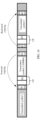
- FIG. 14 is a schematic diagram of time domain structures of three transmitted symbols (1, 2, and 3).
- the transmitted symbol 2 is a DMRS
- the transmitted symbol 1 and the transmitted symbol 2 are non-reference signals
- a copy relationship between a set 2 corresponding to the transmitted symbol 2 and a set 1 corresponding to the transmitted symbol 1 is forward copying
- a copy relationship between the set 2 corresponding to the transmitted symbol 2 and a set 3 corresponding to the transmitted symbol 3 is backward copying.
- the copy relationship between the transmitted symbol 2 and the symbol 1 is forward copying.
- the symbol component R1 in the DMRS is forward copied into the symbol 1, and by analogy, a symbol component D0 in the symbol 1 is forward copied into a symbol (not shown in FIG. 14 ) preceding the symbol 1.
- the copy relationship between the DMRS and the symbol 3 is backward copying.
- the symbol component R2 in the DMRS is backward copied into the symbol 3, and by analogy, a symbol component D3 in the symbol 3 is copied into a symbol (not shown in FIG. 14 ) following the symbol 3.
- a guard interval between symbols can be flexibly configured, and accuracy of a reference signal can also be ensured, so that channel performance can be ensured.
- this application provides a symbol processing method.
- the method includes the following steps.
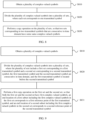
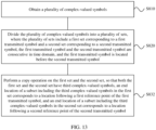
- Step (1) Obtain a plurality of complex-valued symbols.
- Step (2) Divide the plurality of complex-valued symbols into a plurality of sets, where the plurality of sets include a first set and a second set that are the same, the first set corresponds to a first transmitted symbol, the second set corresponds to a second transmitted symbol, the first transmitted symbol and the second transmitted symbol are consecutive in time domain, and the first transmitted symbol is located before the second transmitted symbol.
- a time domain vector corresponding to the first set is the same as a time domain vector corresponding to the second set.
- Step (3) Perform a cyclic shift on the first set and/or the second set, so that complex-valued symbols in a first subset in the first set are the same as complex-valued symbols in a second subset in the second set, where an end location of the first subset corresponds to a first reference point of the first transmitted symbol, and an end location of the second subset corresponds to a second reference point of the second transmitted symbol.
- the first reference point represents an end location of a transmitted symbol
- the second reference point represents a location from which a CP is obtained through truncation in a transmitted symbol.
- the transmitted symbols corresponding to the first set and the second set are reference signals such as DMRSs.
- the method further includes: processing the plurality of sets obtained through the copy operation, to obtain a plurality of transmitted symbols, where the plurality of transmitted symbols include the first transmitted symbol and the second transmitted symbol, the first transmitted symbol and the second transmitted symbol are consecutive in time domain, and the first transmitted symbol is located before the second transmitted symbol.
- a symbol component whose end location is the first reference point in the first transmitted symbol is the same as a symbol component whose end location is the second reference point in the second transmitted symbol, the first reference point represents an end location of a transmitted symbol, and the second reference point represents a location from which a CP is obtained through truncation in a transmitted symbol.
- the symbol component whose end location is the first reference point in the first transmitted symbol and the symbol component whose end location is the second reference point in the second transmitted symbol are enabled to be the same, so that a guard interval between symbols can be flexibly configured by controlling a length of the symbol component.
- a guard interval between symbols can be flexibly configured, and a length of the guard interval can also be flexibly configured based on a user requirement.
- an execution body may be a terminal device or a component (for example, a chip or a circuit) that may be used in a terminal device, or may be a network device or a component (for example, a chip or a circuit) that may be used in a network device.
- FIG. 15 is a schematic block diagram of a symbol processing apparatus 1500 according to an embodiment of this application.
- the apparatus 1500 includes the following units:
- a copy operation is performed on two sets corresponding to two transmitted symbols that are consecutive in time domain, so that the two sets have same complex-valued symbols. This helps generate a first transmitted symbol and a second transmitted symbol whose time domain structures are shown in FIG. 3 . Therefore, in this application, a guard interval between symbols can be flexibly configured when a CP length is fixed.
- the plurality of sets include a first set corresponding to the first transmitted symbol and a second set corresponding to the second transmitted symbol, the first transmitted symbol and the second transmitted symbol are consecutive in time domain, and the first transmitted symbol is located before the second transmitted symbol.
- the copying unit 1530 is configured to perform a first copy operation on the first set and the second set, so that both the first set and the second set have first complex-valued symbols, an end location of a first subset including the first complex-valued symbols in the first set corresponds to a first reference point of the first transmitted symbol, and an end location of a second subset including the first complex-valued symbols in the second set corresponds to a second reference point of the second transmitted symbol, where the first reference point represents an end location of a transmitted symbol, and the second reference point represents a location from which a CP is obtained through truncation in a transmitted symbol.
- the copying unit 1530 is configured to copy the first complex-valued symbols in the first set into the second set.
- a time domain vector corresponding to a first subset including the first complex-valued symbols copied in the first set is x l [1] described above
- a time domain vector corresponding to a second subset including the first complex-valued symbols copied into the second set from the first set is x l +1 [2] described above.
- the first transmitted symbol is a reference signal
- the second transmitted symbol is a non-reference signal
- the copying unit 1530 is configured to copy the first complex-valued symbols in the second set into the first set.
- a time domain vector corresponding to a second subset including the first complex-valued symbols copied in the second set is x l +1 [2] described above
- a time domain vector corresponding to a first subset including the first complex-valued symbols copied into the first set from the second set is x l [1] described above.
- the first transmitted symbol is a non-reference signal
- the second transmitted symbol is a reference signal
- the apparatus 1500 further includes a shifting unit 1540, configured to separately perform a cyclic shift on the first set and the second set based on a same step and direction, so that the end location of the first subset corresponds to a location following the first reference point of the first transmitted symbol, and the end location of the second subset corresponds to a location following the second reference point of the second transmitted symbol.
- a shifting unit 1540 configured to separately perform a cyclic shift on the first set and the second set based on a same step and direction, so that the end location of the first subset corresponds to a location following the first reference point of the first transmitted symbol, and the end location of the second subset corresponds to a location following the second reference point of the second transmitted symbol.
- the copying unit 1530 is further configured to perform a second copy operation on the first set and the second set, so that both the first set and the second set have second complex-valued symbols, a start location of a third subset including the second complex-valued symbols in the first set corresponds to a third reference point of the first transmitted symbol, and a start location of a fourth subset including the second complex-valued symbols in the second set corresponds to the second reference point of the second transmitted symbol, where the third reference point represents a start location of a transmitted symbol.
- the apparatus 1500 further includes a symbol generation unit 1550, configured to process the plurality of sets obtained through the copy operation, to obtain a plurality of transmitted symbols, where the plurality of transmitted symbols include the first transmitted symbol and the second transmitted symbol, the first transmitted symbol and the second transmitted symbol are consecutive in time domain, and the first transmitted symbol is located before the second transmitted symbol.
- a symbol component whose end location is the first reference point in the first transmitted symbol is the same as a symbol component whose end location is the second reference point in the second transmitted symbol, the first reference point represents an end location of a transmitted symbol, and the second reference point represents a location from which a CP is obtained through truncation in a transmitted symbol.
- a guard interval between symbols can be flexibly configured, and a length of the guard interval can also be flexibly configured based on a user requirement.
- the obtaining unit 1510 may include a modulation subunit, configured to modulate an encoded bit stream to obtain a modulated symbol, where the modulated symbol may also be referred to as a complex-valued symbol.
- the obtaining unit 1510 is configured to obtain, based on a PTRS sampling point and the modulated symbol, a plurality of complex-valued symbols for processing by the grouping unit 1520.
- the symbol generation unit 1550 may include a DFT subunit, a subcarrier mapping subunit, an IFFT subunit, and a CP adding subunit.
- the shifting unit 1540 is located between the copying unit 1530 and the symbol generation unit 1550, but this is only one implementation.
- the shifting unit 1540 may be located in the symbol generation unit 1550.
- the shifting unit 1540 is located between the DFT subunit and the IFFT subunit.
- the shifting unit 1540 is located between the IFFT subunit and the CP adding subunit.
- the symbol generation unit 1550 may include a CP adding subunit, an upsampling subunit, and a filtering subunit.
- the obtaining unit 1510 is configured to obtain a plurality of complex-valued symbols.
- the grouping unit 1520 is configured to divide the plurality of complex-valued symbols into a plurality of sets, where the plurality of sets include a first set and a second set that are the same, the first set corresponds to a first transmitted symbol, the second set corresponds to a second transmitted symbol, the first transmitted symbol and the second transmitted symbol are consecutive in time domain, and the first transmitted symbol is located before the second transmitted symbol.
- the shifting unit 1540 is configured to perform a cyclic shift on the first set and/or the second set, so that complex-valued symbols in a first subset in the first set are the same as complex-valued symbols in a second subset in the second set.
- An end location of the first subset corresponds to a first reference point of the first transmitted symbol
- an end location of the second subset corresponds to a second reference point of the second transmitted symbol.
- the first reference point represents an end location of a transmitted symbol
- the second reference point represents a location from which a CP is obtained through truncation in a transmitted symbol.
- both the first transmitted symbol and the second transmitted symbol are reference signals.
- both the first transmitted symbol and the second transmitted symbol are DMRSs.
- the obtaining unit 1510, the grouping unit 1520, and the copying unit 1530 may be implemented by using software, may be implemented by using hardware, or may be implemented by using hardware and software.
- the obtaining unit 1510, the grouping unit 1520, and the copying unit 1530 may be different chips, or may be integrated into one chip or integrated circuit.
- the obtaining unit 1510, the grouping unit 1520, the copying unit 1530, the shifting unit 1540, and the symbol generation unit 1550 each may be implemented by using a processor or a related circuit of a processor.
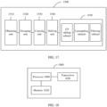
- an embodiment of this application further provides a symbol processing apparatus 1800.
- the apparatus 1800 includes a processor 1810, a memory 1820, and a transceiver 1830.
- the memory 1820 stores a program.
- the processor 1810 is configured to execute the program stored in the memory 1820. Execution of the program stored in the memory 1820 enables the processor 1810 to perform related processing steps in the foregoing method embodiments, and enables the processor 1810 to control the transceiver 1830 to perform receiving/sending related steps in the foregoing method embodiments.
- An embodiment of this application further provides a communication apparatus 1900.
- the communication apparatus 1900 may be a terminal device or a chip.
- the communication device 1900 may be configured to execute the foregoing method embodiments.
- FIG. 19 is a simplified schematic diagram of a structure of the terminal device.
- the terminal device includes a processor, a memory, a radio frequency circuit, an antenna, and an input/output apparatus.
- the processor is mainly configured to: process a communication protocol and communication data, control the terminal device, execute a software program, process data of the software program, and the like.
- the memory is mainly configured to store the software program and the data.
- the radio frequency circuit is mainly configured to: perform conversion between a baseband signal and a radio frequency signal, and process the radio frequency signal.
- the antenna is mainly configured to receive and send a radio frequency signal in a form of an electromagnetic wave.
- the input/output apparatus such as a touchscreen, a display, or a keyboard, is mainly configured to: receive data entered by a user and output data to the user. It should be noted that some types of terminal devices may have no input/output apparatus.
- the processor When data needs to be sent, the processor performs baseband processing on the to-be-sent data, and outputs a baseband signal to the radio frequency circuit. After performing radio frequency processing on the baseband signal, the radio frequency circuit sends a radio frequency signal to the outside in a form of an electromagnetic wave through the antenna.
- the radio frequency circuit receives the radio frequency signal through the antenna, converts the radio frequency signal into a baseband signal, and outputs the baseband signal to the processor.
- the processor converts the baseband signal into data, and processes the data.
- FIG. 19 shows only one memory and one processor. In an actual terminal device product, there may be one or more processors and one or more memories.
- the memory may also be referred to as a storage medium, a storage device, or the like.
- the memory may be disposed independent of the processor, or may be integrated with the processor. This is not limited in this embodiment of this application.
- the antenna and the radio frequency circuit that have receiving and sending functions may be considered as a transceiver unit of the terminal device, and the processor that has a processing function may be considered as a processing unit of the terminal device.
- the terminal device includes a transceiver unit 1910 and a processing unit 1920.
- the transceiver unit 1910 may also be referred to as a transceiver, a transceiver machine, a transceiver apparatus, or the like.
- the processing unit 1920 may also be referred to as a processor, a processing board, a processing module, a processing apparatus, or the like.
- a component that is in the transceiver unit 1910 and that is configured to implement a receiving function may be considered as a receiving unit
- a component that is in the transceiver unit 1910 and that is configured to implement a sending function may be considered as a sending unit.
- the transceiver unit 1910 includes the receiving unit and the sending unit.
- the transceiver unit sometimes may also be referred to as a transceiver machine, a transceiver, a transceiver circuit, or the like.
- the receiving unit sometimes may also be referred to as a receiver machine, a receiver, a receiving circuit, or the like.
- the sending unit sometimes may also be referred to as a transmitter machine, a transmitter, a transmitter circuit, or the like.
- the processing unit 1920 is configured to execute the foregoing method embodiments.
- the transceiver unit 1910 is configured to perform related receiving/sending operations in the foregoing method embodiments.
- the transceiver unit 1910 is configured to send a DFT-s-OFDM symbol or an SC-QAM symbol.
- FIG. 19 is merely an example instead of a limitation.
- the terminal device including the transceiver unit and the processing unit may not depend on the structure shown in FIG. 19 .
- the chip When the communication device 1900 is a chip, the chip includes a transceiver unit and a processing unit.
- the transceiver unit may be an input/output circuit or a communication interface.
- the processing unit may be a processor, a microprocessor, or an integrated circuit integrated on the chip.
- An embodiment of this application further provides a communication device 2000.
- the communication device 2000 may be a network device or a chip.
- the communication device 2000 may be configured to execute the foregoing method embodiments.
- FIG. 20 is a simplified schematic diagram of a structure of the base station.
- the base station includes a part 2010 and a part 2020.
- the part 2010 is mainly configured to: receive and send a radio frequency signal, and perform conversion between a radio frequency signal and a baseband signal.
- the part 2020 is mainly configured to: perform baseband processing, control the base station, and the like.
- the part 2010 may be usually referred to as a transceiver unit, a transceiver machine, a transceiver circuit, a transceiver, or the like.
- the part 2020 is usually a control center of the base station, and may be usually referred to as a processing unit, and is configured to control the base station to perform a processing operation on the network device side in the foregoing method embodiments.
- the transceiver unit in the part 2010 may also be referred to as a transceiver machine, a transceiver, or the like.
- the transceiver unit includes an antenna and a radio frequency unit.
- the radio frequency unit is mainly configured to perform radio frequency processing.
- a component that is in the part 2010 and that is configured to implement a receiving function may be considered as a receiving unit, and a component that is configured to implement a sending function may be considered as a sending unit.
- the part 2010 includes the receiving unit and the sending unit.
- the receiving unit may also be referred to as a receiver machine, a receiver, a receiver circuit, or the like.
- the sending unit may be referred to as a transmitter machine, a transmitter, a transmitter circuit, or the like.
- the part 2020 may include one or more boards, and each board may include one or more processors and one or more memories.
- the processor is configured to read and execute a program in the memory to implement a baseband processing function and control the base station. If there are a plurality of boards, the boards may be interconnected to enhance a processing capability.
- the plurality of boards may share one or more processors, or the plurality of boards may share one or more memories, or the plurality of boards may simultaneously share one or more processors.
- the part 2020 is configured to execute the foregoing method embodiments.
- the part 2010 is configured to perform related receiving/sending operations in the foregoing method embodiments.
- the part 2010 is configured to send a DFT-s-OFDM symbol or an SC-QAM symbol.
- FIG. 10 is merely an example instead of a limitation.
- the network device including the transceiver unit and the processing unit may not depend on the structure shown in FIG. 10 .
- the chip When the communication device 2000 is a chip, the chip includes a transceiver unit and a processing unit.
- the transceiver unit may be an input/output circuit or a communication interface.
- the processing unit may be a processor, a microprocessor, or an integrated circuit integrated on the chip.
- the terminal device in the embodiments of this application includes a handheld device, a vehicle-mounted device, a wearable device, or a computing device that has a wireless communication function.
- the terminal device may be user equipment (UE), an access terminal, a subscriber unit, a subscriber station, a mobile station, a remote station, a remote terminal, a mobile device, a user terminal, a terminal, a wireless communication device, a user agent, or a user apparatus.
- the terminal device may be a mobile phone (mobile phone), a tablet computer, or a computer that has a wireless transceiver function.
- the terminal device may alternatively be a virtual reality (VR) terminal device, an augmented reality (AR) terminal device, a wireless terminal in industrial control, a wireless terminal in self-driving, a wireless terminal in telemedicine, a wireless terminal in a smart grid, a wireless terminal in a smart city (smart city), a wireless terminal in a smart home (smart home), or the like.
- the terminal device may be a terminal device in a 5G network, a terminal device in a future evolved public land mobile network (PLMN), or the like.
- PLMN public land mobile network
- the network device in the embodiments of this application may be configured to communicate with one or more terminal devices, or may be configured to communicate with one or more base stations that have some terminal functions (for example, communication between a macro base station and a micro base station, such as an access point).
- the network device may be referred to as a base station.
- the base station may be in a plurality of forms, for example, a macro base station, a micro base station, a relay station, and an access point.
- the network device in the embodiments of this application may be a base station in NR, a base transceiver station (BTS) in a global system for mobile communications (GSM) or code division multiple access (CDMA), a NodeB (NB) in a wideband code division multiple access (WCDMA) system, or an evolved NodeB (eNB or eNodeB) in an LTE system.
- the base station in 5G NR may also be referred to as a transmission reception point (TRP) or a next generation NodeB (gNB).
- TRP transmission reception point
- gNB next generation NodeB
- An embodiment of this application further provides a computer-readable storage medium.
- the computer-readable storage medium stores a computer program.
- the computer program When the computer program is executed by a computer, the computer is enabled to implement the method in the foregoing method embodiments.
- An embodiment of this application further provides a computer program product including instructions.
- the instructions When the instructions are executed by a computer, the computer is enabled to implement the method in the foregoing method embodiments.
- the terminal device or the network device includes a hardware layer, an operating system layer running above the hardware layer, and an application layer running above the operating system layer.
- the hardware layer includes hardware such as a central processing unit (CPU), a memory management unit (MMU), and a memory (which is also referred to as a main memory).
- the operating system may be any one or more computer operating systems that implement service processing through a process (process), for example, a Linux operating system, a Unix operating system, an Android operating system, an iOS operating system, or a Windows operating system.
- the application layer includes applications such as a browser, an address book, word processing software, and instant messaging software.
- a specific structure of an execution body of a method provided in the embodiments of this application is not specifically limited in the embodiments of this application, provided that a program that records code of the method provided in the embodiments of this application can be run to perform communication according to the method provided in the embodiments of this application.
- the method provided in the embodiments of this application may be performed by the terminal device or the network device, or by a function module, in the terminal device or network device, that can invoke and execute the program.
- aspects or features of this application may be implemented as a method, an apparatus, or a product that uses standard programming and/or engineering technologies.
- the term "product" used in this application covers a computer program that can be accessed from any computer-readable component, carrier, or medium.
- the computer-readable medium may include but is not limited to: a magnetic storage component (for example, a hard disk, a floppy disk, or a magnetic tape), an optical disc (for example, a compact disc (CD) or a digital versatile disc (DVD)), a smart card, and a flash memory component (for example, an erasable programmable read-only memory (EPROM), a card, a stick, or a key drive).
- a magnetic storage component for example, a hard disk, a floppy disk, or a magnetic tape
- an optical disc for example, a compact disc (CD) or a digital versatile disc (DVD)
- a smart card for example, an erasable programmable read-only memory (EPROM),
- various storage media described in this specification may represent one or more devices and/or other machine-readable media that are configured to store information.
- machine-readable media may include but is not limited to a radio channel and various other media that can store, include, and/or carry instructions and/or data.
- the processor mentioned in the embodiments of this application may be a CPU, or may be another general-purpose processor, a digital signal processor (DSP), an application-specific integrated circuit (ASIC), a field programmable gate array (FPGA) or another programmable logic device, a discrete gate or a transistor logic device, a discrete hardware component, or the like.
- the general-purpose processor may be a microprocessor, or the processor may be any conventional processor, or the like.
- the memory mentioned in the embodiments of this application may be a volatile memory or a nonvolatile memory, or may include a volatile memory and a nonvolatile memory.
- the nonvolatile memory may be a read-only memory (ROM), a programmable read-only memory (PROM), an EPROM, an electrically erasable programmable read-only memory (EEPROM), or a flash memory.
- the volatile memory may be a random access memory (RAM), used as an external cache.
- RAMs may be used, for example, a static random access memory (SRAM), a dynamic random access memory (DRAM), a synchronous dynamic random access memory (SDRAM), a double data rate synchronous dynamic random access memory (DDR SDRAM), an enhanced synchronous dynamic random access memory (ESDRAM), a synchlink dynamic random access memory (SLDRAM), and a direct rambus random access memory (DR RAM).
- SRAM static random access memory
- DRAM dynamic random access memory
- SDRAM synchronous dynamic random access memory
- DDR SDRAM double data rate synchronous dynamic random access memory
- ESDRAM enhanced synchronous dynamic random access memory
- SLDRAM synchlink dynamic random access memory
- DR RAM direct rambus random access memory
- the processor is a general-purpose processor, a DSP, an ASIC, an FPGA or another programmable logic device, a discrete gate or a transistor logic device, or a discrete hardware component
- the memory is integrated into the processor.
- the memory described in this specification aims to include but is not limited to these memories and any memory of another proper type.
- the disclosed system, apparatus, and method may be implemented in other manners.
- the apparatus embodiments described above are merely examples.
- division into the units is merely logical function division, and may be other division during actual implementation.
- a plurality of units or components may be combined or integrated into another system, or some features may be ignored or may not be performed.
- the displayed or discussed mutual couplings or direct couplings or communication connections may be implemented through some interfaces.
- the indirect couplings or communication connections between the apparatuses or units may be implemented in electrical, mechanical, or other forms.
- the units described as separate parts may or may not be physically separate, and parts displayed as units may or may not be physical units, may be located in one position, or may be distributed on a plurality of network units. Some or all of the units may be selected based on actual requirements to achieve the objectives of the solutions of the embodiments.
- the functions When the functions are implemented in a form of a software functional unit and sold or used as an independent product, the functions may be stored in a computer-readable storage medium. Based on such an understanding, the technical solutions of this application essentially, or the part contributing to the conventional technology, or some of the technical solutions may be implemented in a form of a software product.
- the computer software product is stored in a storage medium, and includes several instructions for instructing a computer device (which may be a personal computer, a server, or a network device) to perform all or some of the steps of the methods described in the embodiments of this application.
- the foregoing storage medium includes any medium that can store program code, such as a USB flash drive, a removable hard disk, a ROM, a RAM, a magnetic disk, or an optical disc.
Landscapes
- Engineering & Computer Science (AREA)
- Signal Processing (AREA)
- Computer Networks & Wireless Communication (AREA)
- Power Engineering (AREA)
- Mobile Radio Communication Systems (AREA)
Claims (12)
- Procédé de traitement de symboles par ordinateur, comprenant :l'obtention (S810) d'une pluralité de symboles de valeurs complexes ;la division (S820) de la pluralité de symboles de valeurs complexes en une pluralité d'ensembles, dans lequel chaque ensemble correspond à un symbole transmis ; etla réalisation (S830) d'une opération de copie sur la pluralité d'ensembles, de telle sorte que deux ensembles correspondant à deux symboles transmis qui sont consécutifs dans le domaine temporel aient certains symboles de valeurs complexes identiques,dans lequel la pluralité d'ensembles comprend un premier ensemble correspondant à un premier symbole transmis et un second ensemble correspondant à un second symbole transmis, le premier symbole transmis et le second symbole transmis sont consécutifs dans le domaine temporel, et le premier symbole transmis est situé avant le second symbole transmis ; etla réalisation (S830) d'une opération de copie sur la pluralité d'ensembles comprend :la réalisation (S831) d'une première opération de copie sur le premier ensemble et le second ensemble, de telle sorte que le premier ensemble et le second ensemble aient tous deux des premiers symboles de valeurs complexes, qu'un emplacement final d'un premier sous-ensemble constitué des premiers symboles de valeurs complexes dans le premier ensemble corresponde à un premier point de référence du premier symbole transmis, et qu'un emplacement final d'un deuxième sous-ensemble constitué des premiers symboles de valeurs complexes dans le second ensemble corresponde à un deuxième point de référence du second symbole transmis, dans lequel le premier point de référence représente un emplacement final d'un symbole transmis,et le deuxième point de référence représente un emplacement à partir duquel un préfixe cyclique est obtenu par troncature dans un symbole transmis, et dans lequel le préfixe cyclique est ajouté en fonction des ensembles obtenus par l'opération de copie.
- Procédé selon la revendication 1, dans lequel un vecteur de domaine temporel correspondant au premier sous-ensemble est un sous-vecteur xl [1] dans un vecteur de domaine temporel correspondant au premier ensemble :

un vecteur de domaine temporel correspondant au deuxième sous-ensemble est un sous-vecteur x l+1[2] dans un vecteur de domaine temporel correspondant au second ensemble :
M représente des dimensions des vecteurs de domaine temporel correspondant séparément au premier ensemble et au second ensemble,
- Procédé selon la revendication 1 ou 2, dans lequel la réalisation (S831) d'une première opération de copie sur le premier ensemble et le second ensemble comprend :
la copie des premiers symboles de valeurs complexes du premier ensemble dans le second ensemble. - Procédé selon la revendication 1 ou 2, dans lequel la réalisation (S831) d'une opération de copie sur le premier ensemble et le second ensemble comprend :
la copie des premiers symboles de valeurs complexes du second ensemble dans le premier ensemble. - Procédé selon l'une quelconque des revendications 1 à 4, le procédé comprenant en outre :
après la réalisation (S831) d'une première opération de copie sur le premier ensemble et le second ensemble, la réalisation séparément (S840) d'un décalage cyclique sur le premier ensemble et le second ensemble selon un même pas et une même direction, de telle sorte que l'emplacement final du premier sous-ensemble corresponde à un emplacement qui suit le premier point de référence du premier symbole transmis, et que l'emplacement final du deuxième sous-ensemble corresponde à un emplacement qui suit le deuxième point de référence du second symbole transmis. - Procédé selon l'une quelconque des revendications 1 à 4, le procédé comprenant en outre :la réalisation d'une seconde opération de copie sur le premier ensemble et le second ensemble, de telle sorte que le premier ensemble et le second ensemble aient tous deux des seconds symboles de valeurs complexes, qu'un emplacement de départ d'un troisième sous-ensemble constitué des seconds symboles de valeurs complexes du premier ensemble corresponde à un troisième point de référence du premier symbole transmis, et qu'un emplacement de départ d'un quatrième sous-ensemble constitué des seconds symboles de valeurs complexes du second ensemble corresponde au deuxième point de référence du second symbole transmis, dans lequelle troisième point de référence représente un emplacement de départ d'un symbole transmis.
- Procédé selon la revendication 3, dans lequel le premier symbole transmis est un signal de référence, et le second symbole transmis est un signal non de référence.
- Procédé selon la revendication 4, dans lequel le premier symbole transmis est un signal non de référence, et le second symbole transmis est un signal de référence.
- Procédé selon l'une quelconque des revendications 1 à 8, le procédé comprenant en outre :le traitement de la pluralité d'ensembles obtenus par l'opération de copie, pour obtenir une pluralité de symboles transmis, dans lequel la pluralité de symboles transmis comprend le premier symbole transmis et le second symbole transmis, le premier symbole transmis et le second symbole transmis sont consécutifs dans le domaine temporel, et le premier symbole transmis est situé avant le second symbole transmis, dans lequelun composant de symbole dont l'emplacement final est le premier point de référence dans le premier symbole transmis est le même qu'un composant de symbole dont l'emplacement final est le deuxième point de référence dans le second symbole transmis, le premier point de référence représente un emplacement final d'un symbole transmis, et le deuxième point de référence représente un emplacement à partir duquel un préfixe cyclique est obtenu par troncature dans un symbole transmis.
- Appareil de communication (1500, 1800, 1900, 2000), configuré pour réaliser le procédé selon l'une quelconque des revendications 1 à 9.
- Support de stockage lisible par ordinateur, dans lequel le support de stockage lisible par ordinateur stocke un programme d'ordinateur ; et le programme d'ordinateur, à son exécution par un ordinateur, amenant l'ordinateur à entreprendre le procédé selon l'une quelconque des revendications 1 à 9.
- Produit-programme comprenant un programme d'ordinateur qui, lorsque le programme d'ordinateur est exécuté par un ordinateur, amène l'ordinateur à entreprendre le procédé selon l'une quelconque des revendications 1 à 9.
Applications Claiming Priority (2)
| Application Number | Priority Date | Filing Date | Title |
|---|---|---|---|
| CN201910591582.8A CN112187682B (zh) | 2019-07-02 | 2019-07-02 | 符号处理的方法与装置 |
| PCT/CN2020/095627 WO2021000711A1 (fr) | 2019-07-02 | 2020-06-11 | Procédé et appareil de traitement de symboles |
Publications (3)
| Publication Number | Publication Date |
|---|---|
| EP3962007A1 EP3962007A1 (fr) | 2022-03-02 |
| EP3962007A4 EP3962007A4 (fr) | 2022-08-10 |
| EP3962007B1 true EP3962007B1 (fr) | 2025-01-29 |
Family
ID=73915850
Family Applications (1)
| Application Number | Title | Priority Date | Filing Date |
|---|---|---|---|
| EP20835505.7A Active EP3962007B1 (fr) | 2019-07-02 | 2020-06-11 | Procédé et appareil de traitement de symboles |
Country Status (4)
| Country | Link |
|---|---|
| US (1) | US11943086B2 (fr) |
| EP (1) | EP3962007B1 (fr) |
| CN (1) | CN112187682B (fr) |
| WO (1) | WO2021000711A1 (fr) |
Families Citing this family (5)
| Publication number | Priority date | Publication date | Assignee | Title |
|---|---|---|---|---|
| US11678285B2 (en) * | 2021-07-28 | 2023-06-13 | Qualcomm Incorporated | Synchronization signal block design using a single carrier quadrature amplitude modulation waveform |
| CN115776430A (zh) * | 2021-09-07 | 2023-03-10 | 华为技术有限公司 | 一种通信方法及装置 |
| CN118233265A (zh) * | 2022-12-20 | 2024-06-21 | 北京三星通信技术研究有限公司 | 用于发送和接收信号的方法和装置 |
| CN120017453A (zh) * | 2023-11-16 | 2025-05-16 | 华为技术有限公司 | 一种通信方法及装置 |
| CN120074997A (zh) * | 2023-11-29 | 2025-05-30 | 华为技术有限公司 | 一种符号处理的方法及通信装置 |
Family Cites Families (19)
| Publication number | Priority date | Publication date | Assignee | Title |
|---|---|---|---|---|
| US6842487B1 (en) * | 2000-09-22 | 2005-01-11 | Telefonaktiebolaget Lm Ericsson (Publ) | Cyclic delay diversity for mitigating intersymbol interference in OFDM systems |
| WO2004021616A1 (fr) * | 2002-08-28 | 2004-03-11 | Fujitsu Limited | Appareil de transmission/reception et procede de transmission/reception |
| KR101121069B1 (ko) * | 2005-03-08 | 2012-03-20 | 꼼미사리아 아 레네르지 아또미끄 에 오 에네르지 알떼르나띠브스 | 추정된 복소수 심벌들의 유연한 복조를 위한 방법 |
| US20070165728A1 (en) * | 2006-01-17 | 2007-07-19 | Vladimir Parizhsky | Multi-symbol signals including an initial symbol and an extension portion |
| WO2008056901A1 (fr) * | 2006-11-10 | 2008-05-15 | Electronics And Telecommunications Research Institute | Émetteurs pour étendre l'intervalle de protection d'un équipement utilisateurs individuel dans des systèmes d'accès mrof |
| US20100111017A1 (en) * | 2007-04-19 | 2010-05-06 | Electronics And Telecommunications Research Institute | Method and apparatus of generating signals for initial ranging in ofdma system |
| US8743855B2 (en) * | 2007-12-17 | 2014-06-03 | Lg Electronics Inc. | Method of generating data and transmitting synchronization channel in mobile communication system |
| KR101530536B1 (ko) * | 2008-03-03 | 2015-06-22 | 삼성전자주식회사 | 광대역 무선통신 시스템에서 레인징 신호를 이용한 채널 품질 측정 장치 및 방법 |
| CN102273113A (zh) * | 2009-01-08 | 2011-12-07 | 夏普株式会社 | 发送装置、发送方法、通信系统以及通信方法 |
| US10027518B2 (en) * | 2010-02-12 | 2018-07-17 | Lg Electronics Inc. | Broadcasting signal transmitter/receiver and broadcasting signal transmission/reception method |
| GB2511796A (en) * | 2013-03-13 | 2014-09-17 | Sony Corp | Transmitters, receivers and methods of transmitting and receiving |
| EP3247079A4 (fr) * | 2015-02-10 | 2018-02-14 | Huawei Technologies Co., Ltd. | Procédé, appareil, dispositif et système de réduction de rapport puissance maximale sur puissance moyenne |
| CN107852393B (zh) * | 2015-08-21 | 2019-11-29 | 华为技术有限公司 | 发送、解调数据的方法、设备及系统 |
| US10200994B2 (en) * | 2016-05-20 | 2019-02-05 | Qualcomm Incorporated | Non-equal bit allocation for coexistence with scaled numerology systems |
| CN107888532B (zh) * | 2016-09-30 | 2020-04-14 | 华为技术有限公司 | 数据传输方法及通信设备 |
| US10700910B2 (en) * | 2017-06-16 | 2020-06-30 | Qualcomm Incorporated | Single carrier waveform data transmission and reception based on configurable DFT window |
| EP3657748B1 (fr) * | 2018-11-20 | 2021-07-28 | Mitsubishi Electric R&D Centre Europe B.V. | Générateur de symboles de préambule et son procédé de modulation ofdm à répartition de transformée de fourier discrète |
| CN112187690B (zh) * | 2019-07-02 | 2022-10-04 | 华为技术有限公司 | 符号处理的方法与装置 |
| WO2021081831A1 (fr) * | 2019-10-30 | 2021-05-06 | 华为技术有限公司 | Procédé et appareil de traitement de symboles |
-
2019
- 2019-07-02 CN CN201910591582.8A patent/CN112187682B/zh active Active
-
2020
- 2020-06-11 EP EP20835505.7A patent/EP3962007B1/fr active Active
- 2020-06-11 WO PCT/CN2020/095627 patent/WO2021000711A1/fr not_active Ceased
-
2021
- 2021-12-29 US US17/564,450 patent/US11943086B2/en active Active
Also Published As
| Publication number | Publication date |
|---|---|
| WO2021000711A1 (fr) | 2021-01-07 |
| US11943086B2 (en) | 2024-03-26 |
| CN112187682B (zh) | 2022-08-26 |
| CN112187682A (zh) | 2021-01-05 |
| EP3962007A4 (fr) | 2022-08-10 |
| US20220123979A1 (en) | 2022-04-21 |
| EP3962007A1 (fr) | 2022-03-02 |
Similar Documents
| Publication | Publication Date | Title |
|---|---|---|
| EP3989499B1 (fr) | Procédé et appareil de traitement de symboles | |
| EP3962007B1 (fr) | Procédé et appareil de traitement de symboles | |
| US11991112B2 (en) | Symbol processing method and apparatus | |
| US12301397B2 (en) | Symbol processing method and apparatus | |
| US10312990B2 (en) | Signal sending or receiving method and device | |
| US20240388411A1 (en) | Symbol Processing Method and Apparatus | |
| US11843485B2 (en) | Symbol processing method and apparatus | |
| CN111865517A (zh) | 发送参考信号的方法和装置 | |
| WO2018059350A1 (fr) | Procédé, appareil et système de traitement de données | |
| WO2018024127A1 (fr) | Procédé d'émission de signaux et dispositif de réseau | |
| CN107666455A (zh) | 一种传输信号的方法及网络设备 | |
| US11563612B2 (en) | Transmission method and first communication device | |
| KR102591141B1 (ko) | 참조 신호 송수신 방법 및 장치 | |
| CN121907645A (zh) | 一种符号处理的方法与装置 | |
| WO2025020200A1 (fr) | Procédé de communication, appareil de communication et support de stockage lisible par ordinateur | |
| WO2024094132A1 (fr) | Procédé de communication et appareil de communication |
Legal Events
| Date | Code | Title | Description |
|---|---|---|---|
| STAA | Information on the status of an ep patent application or granted ep patent |
Free format text: STATUS: THE INTERNATIONAL PUBLICATION HAS BEEN MADE |
|
| PUAI | Public reference made under article 153(3) epc to a published international application that has entered the european phase |
Free format text: ORIGINAL CODE: 0009012 |
|
| STAA | Information on the status of an ep patent application or granted ep patent |
Free format text: STATUS: REQUEST FOR EXAMINATION WAS MADE |
|
| 17P | Request for examination filed |
Effective date: 20211123 |
|
| AK | Designated contracting states |
Kind code of ref document: A1 Designated state(s): AL AT BE BG CH CY CZ DE DK EE ES FI FR GB GR HR HU IE IS IT LI LT LU LV MC MK MT NL NO PL PT RO RS SE SI SK SM TR |
|
| A4 | Supplementary search report drawn up and despatched |
Effective date: 20220708 |
|
| RIC1 | Information provided on ipc code assigned before grant |
Ipc: H04J 13/00 20110101ALN20220704BHEP Ipc: H04L 27/26 20060101ALI20220704BHEP Ipc: H04L 5/00 20060101ALI20220704BHEP Ipc: H04L 25/03 20060101AFI20220704BHEP |
|
| DAV | Request for validation of the european patent (deleted) | ||
| DAX | Request for extension of the european patent (deleted) | ||
| GRAP | Despatch of communication of intention to grant a patent |
Free format text: ORIGINAL CODE: EPIDOSNIGR1 |
|
| STAA | Information on the status of an ep patent application or granted ep patent |
Free format text: STATUS: GRANT OF PATENT IS INTENDED |
|
| RIC1 | Information provided on ipc code assigned before grant |
Ipc: H04J 13/00 20110101ALN20240912BHEP Ipc: H04L 27/26 20060101ALI20240912BHEP Ipc: H04L 5/00 20060101ALI20240912BHEP Ipc: H04L 25/03 20060101AFI20240912BHEP |
|
| INTG | Intention to grant announced |
Effective date: 20240923 |
|
| RIC1 | Information provided on ipc code assigned before grant |
Ipc: H04J 13/00 20110101ALN20240913BHEP Ipc: H04L 27/26 20060101ALI20240913BHEP Ipc: H04L 5/00 20060101ALI20240913BHEP Ipc: H04L 25/03 20060101AFI20240913BHEP |
|
| GRAS | Grant fee paid |
Free format text: ORIGINAL CODE: EPIDOSNIGR3 |
|
| GRAA | (expected) grant |
Free format text: ORIGINAL CODE: 0009210 |
|
| STAA | Information on the status of an ep patent application or granted ep patent |
Free format text: STATUS: THE PATENT HAS BEEN GRANTED |
|
| AK | Designated contracting states |
Kind code of ref document: B1 Designated state(s): AL AT BE BG CH CY CZ DE DK EE ES FI FR GB GR HR HU IE IS IT LI LT LU LV MC MK MT NL NO PL PT RO RS SE SI SK SM TR |
|
| REG | Reference to a national code |
Ref country code: GB Ref legal event code: FG4D |
|
| REG | Reference to a national code |
Ref country code: CH Ref legal event code: EP |
|
| REG | Reference to a national code |
Ref country code: DE Ref legal event code: R096 Ref document number: 602020045589 Country of ref document: DE |
|
| REG | Reference to a national code |
Ref country code: IE Ref legal event code: FG4D |
|
| REG | Reference to a national code |
Ref country code: NL Ref legal event code: MP Effective date: 20250129 |
|
| PG25 | Lapsed in a contracting state [announced via postgrant information from national office to epo] |
Ref country code: NL Free format text: LAPSE BECAUSE OF FAILURE TO SUBMIT A TRANSLATION OF THE DESCRIPTION OR TO PAY THE FEE WITHIN THE PRESCRIBED TIME-LIMIT Effective date: 20250129 |
|
| PG25 | Lapsed in a contracting state [announced via postgrant information from national office to epo] |
Ref country code: RS Free format text: LAPSE BECAUSE OF FAILURE TO SUBMIT A TRANSLATION OF THE DESCRIPTION OR TO PAY THE FEE WITHIN THE PRESCRIBED TIME-LIMIT Effective date: 20250429 |
|
| PG25 | Lapsed in a contracting state [announced via postgrant information from national office to epo] |
Ref country code: FI Free format text: LAPSE BECAUSE OF FAILURE TO SUBMIT A TRANSLATION OF THE DESCRIPTION OR TO PAY THE FEE WITHIN THE PRESCRIBED TIME-LIMIT Effective date: 20250129 |
|
| PG25 | Lapsed in a contracting state [announced via postgrant information from national office to epo] |
Ref country code: PL Free format text: LAPSE BECAUSE OF FAILURE TO SUBMIT A TRANSLATION OF THE DESCRIPTION OR TO PAY THE FEE WITHIN THE PRESCRIBED TIME-LIMIT Effective date: 20250129 |
|
| PGFP | Annual fee paid to national office [announced via postgrant information from national office to epo] |
Ref country code: DE Payment date: 20250429 Year of fee payment: 6 |
|
| PG25 | Lapsed in a contracting state [announced via postgrant information from national office to epo] |
Ref country code: ES Free format text: LAPSE BECAUSE OF FAILURE TO SUBMIT A TRANSLATION OF THE DESCRIPTION OR TO PAY THE FEE WITHIN THE PRESCRIBED TIME-LIMIT Effective date: 20250129 |
|
| PGFP | Annual fee paid to national office [announced via postgrant information from national office to epo] |
Ref country code: GB Payment date: 20250501 Year of fee payment: 6 |
|
| REG | Reference to a national code |
Ref country code: LT Ref legal event code: MG9D |
|
| PG25 | Lapsed in a contracting state [announced via postgrant information from national office to epo] |
Ref country code: IS Free format text: LAPSE BECAUSE OF FAILURE TO SUBMIT A TRANSLATION OF THE DESCRIPTION OR TO PAY THE FEE WITHIN THE PRESCRIBED TIME-LIMIT Effective date: 20250529 Ref country code: NO Free format text: LAPSE BECAUSE OF FAILURE TO SUBMIT A TRANSLATION OF THE DESCRIPTION OR TO PAY THE FEE WITHIN THE PRESCRIBED TIME-LIMIT Effective date: 20250429 |
|
| REG | Reference to a national code |
Ref country code: AT Ref legal event code: MK05 Ref document number: 1764537 Country of ref document: AT Kind code of ref document: T Effective date: 20250129 |
|
| PG25 | Lapsed in a contracting state [announced via postgrant information from national office to epo] |
Ref country code: HR Free format text: LAPSE BECAUSE OF FAILURE TO SUBMIT A TRANSLATION OF THE DESCRIPTION OR TO PAY THE FEE WITHIN THE PRESCRIBED TIME-LIMIT Effective date: 20250129 |
|
| PG25 | Lapsed in a contracting state [announced via postgrant information from national office to epo] |
Ref country code: LV Free format text: LAPSE BECAUSE OF FAILURE TO SUBMIT A TRANSLATION OF THE DESCRIPTION OR TO PAY THE FEE WITHIN THE PRESCRIBED TIME-LIMIT Effective date: 20250129 Ref country code: PT Free format text: LAPSE BECAUSE OF FAILURE TO SUBMIT A TRANSLATION OF THE DESCRIPTION OR TO PAY THE FEE WITHIN THE PRESCRIBED TIME-LIMIT Effective date: 20250529 |
|
| PG25 | Lapsed in a contracting state [announced via postgrant information from national office to epo] |
Ref country code: GR Free format text: LAPSE BECAUSE OF FAILURE TO SUBMIT A TRANSLATION OF THE DESCRIPTION OR TO PAY THE FEE WITHIN THE PRESCRIBED TIME-LIMIT Effective date: 20250430 Ref country code: BG Free format text: LAPSE BECAUSE OF FAILURE TO SUBMIT A TRANSLATION OF THE DESCRIPTION OR TO PAY THE FEE WITHIN THE PRESCRIBED TIME-LIMIT Effective date: 20250129 |
|
| PG25 | Lapsed in a contracting state [announced via postgrant information from national office to epo] |
Ref country code: AT Free format text: LAPSE BECAUSE OF FAILURE TO SUBMIT A TRANSLATION OF THE DESCRIPTION OR TO PAY THE FEE WITHIN THE PRESCRIBED TIME-LIMIT Effective date: 20250129 |
|
| PG25 | Lapsed in a contracting state [announced via postgrant information from national office to epo] |
Ref country code: SE Free format text: LAPSE BECAUSE OF FAILURE TO SUBMIT A TRANSLATION OF THE DESCRIPTION OR TO PAY THE FEE WITHIN THE PRESCRIBED TIME-LIMIT Effective date: 20250129 |
|
| PG25 | Lapsed in a contracting state [announced via postgrant information from national office to epo] |
Ref country code: SM Free format text: LAPSE BECAUSE OF FAILURE TO SUBMIT A TRANSLATION OF THE DESCRIPTION OR TO PAY THE FEE WITHIN THE PRESCRIBED TIME-LIMIT Effective date: 20250129 |
|
| PG25 | Lapsed in a contracting state [announced via postgrant information from national office to epo] |
Ref country code: DK Free format text: LAPSE BECAUSE OF FAILURE TO SUBMIT A TRANSLATION OF THE DESCRIPTION OR TO PAY THE FEE WITHIN THE PRESCRIBED TIME-LIMIT Effective date: 20250129 |
|
| PG25 | Lapsed in a contracting state [announced via postgrant information from national office to epo] |
Ref country code: IT Free format text: LAPSE BECAUSE OF FAILURE TO SUBMIT A TRANSLATION OF THE DESCRIPTION OR TO PAY THE FEE WITHIN THE PRESCRIBED TIME-LIMIT Effective date: 20250129 |
|
| PG25 | Lapsed in a contracting state [announced via postgrant information from national office to epo] |
Ref country code: EE Free format text: LAPSE BECAUSE OF FAILURE TO SUBMIT A TRANSLATION OF THE DESCRIPTION OR TO PAY THE FEE WITHIN THE PRESCRIBED TIME-LIMIT Effective date: 20250129 Ref country code: CZ Free format text: LAPSE BECAUSE OF FAILURE TO SUBMIT A TRANSLATION OF THE DESCRIPTION OR TO PAY THE FEE WITHIN THE PRESCRIBED TIME-LIMIT Effective date: 20250129 |
|
| PG25 | Lapsed in a contracting state [announced via postgrant information from national office to epo] |
Ref country code: RO Free format text: LAPSE BECAUSE OF FAILURE TO SUBMIT A TRANSLATION OF THE DESCRIPTION OR TO PAY THE FEE WITHIN THE PRESCRIBED TIME-LIMIT Effective date: 20250129 |
|
| PG25 | Lapsed in a contracting state [announced via postgrant information from national office to epo] |
Ref country code: SK Free format text: LAPSE BECAUSE OF FAILURE TO SUBMIT A TRANSLATION OF THE DESCRIPTION OR TO PAY THE FEE WITHIN THE PRESCRIBED TIME-LIMIT Effective date: 20250129 |
|
| REG | Reference to a national code |
Ref country code: DE Ref legal event code: R097 Ref document number: 602020045589 Country of ref document: DE |
|
| PLBE | No opposition filed within time limit |
Free format text: ORIGINAL CODE: 0009261 |
|
| STAA | Information on the status of an ep patent application or granted ep patent |
Free format text: STATUS: NO OPPOSITION FILED WITHIN TIME LIMIT |
|
| REG | Reference to a national code |
Ref country code: CH Ref legal event code: L10 Free format text: ST27 STATUS EVENT CODE: U-0-0-L10-L00 (AS PROVIDED BY THE NATIONAL OFFICE) Effective date: 20251210 |
|
| 26N | No opposition filed |
Effective date: 20251030 |
|
| REG | Reference to a national code |
Ref country code: CH Ref legal event code: H13 Free format text: ST27 STATUS EVENT CODE: U-0-0-H10-H13 (AS PROVIDED BY THE NATIONAL OFFICE) Effective date: 20260127 |
|
| PG25 | Lapsed in a contracting state [announced via postgrant information from national office to epo] |
Ref country code: MC Free format text: LAPSE BECAUSE OF FAILURE TO SUBMIT A TRANSLATION OF THE DESCRIPTION OR TO PAY THE FEE WITHIN THE PRESCRIBED TIME-LIMIT Effective date: 20250129 |
|
| PG25 | Lapsed in a contracting state [announced via postgrant information from national office to epo] |
Ref country code: LU Free format text: LAPSE BECAUSE OF NON-PAYMENT OF DUE FEES Effective date: 20250611 |
|
| REG | Reference to a national code |
Ref country code: BE Ref legal event code: MM Effective date: 20250630 |
|
| PG25 | Lapsed in a contracting state [announced via postgrant information from national office to epo] |
Ref country code: IE Free format text: LAPSE BECAUSE OF NON-PAYMENT OF DUE FEES Effective date: 20250611 |
|
| PG25 | Lapsed in a contracting state [announced via postgrant information from national office to epo] |
Ref country code: BE Free format text: LAPSE BECAUSE OF NON-PAYMENT OF DUE FEES Effective date: 20250630 |
|
| PG25 | Lapsed in a contracting state [announced via postgrant information from national office to epo] |
Ref country code: FR Free format text: LAPSE BECAUSE OF NON-PAYMENT OF DUE FEES Effective date: 20250630 |
|
| PG25 | Lapsed in a contracting state [announced via postgrant information from national office to epo] |
Ref country code: CH Free format text: LAPSE BECAUSE OF NON-PAYMENT OF DUE FEES Effective date: 20250630 |