EP3962071A1 - Bildanzeigevorrichtung - Google Patents
Bildanzeigevorrichtung Download PDFInfo
- Publication number
- EP3962071A1 EP3962071A1 EP20794043.8A EP20794043A EP3962071A1 EP 3962071 A1 EP3962071 A1 EP 3962071A1 EP 20794043 A EP20794043 A EP 20794043A EP 3962071 A1 EP3962071 A1 EP 3962071A1
- Authority
- EP
- European Patent Office
- Prior art keywords
- display panel
- antenna unit
- plate
- display device
- image display
- Prior art date
- Legal status (The legal status is an assumption and is not a legal conclusion. Google has not performed a legal analysis and makes no representation as to the accuracy of the status listed.)
- Pending
Links
Images




Classifications
-
- G—PHYSICS
- G06—COMPUTING OR CALCULATING; COUNTING
- G06F—ELECTRIC DIGITAL DATA PROCESSING
- G06F1/00—Details not covered by groups G06F3/00 - G06F13/00 and G06F21/00
- G06F1/16—Constructional details or arrangements
- G06F1/18—Packaging or power distribution
- G06F1/181—Enclosures
- G06F1/182—Enclosures with special features, e.g. for use in industrial environments; grounding or shielding against radio frequency interference [RFI] or electromagnetical interference [EMI]
-
- G—PHYSICS
- G06—COMPUTING OR CALCULATING; COUNTING
- G06F—ELECTRIC DIGITAL DATA PROCESSING
- G06F1/00—Details not covered by groups G06F3/00 - G06F13/00 and G06F21/00
- G06F1/16—Constructional details or arrangements
- G06F1/1601—Constructional details related to the housing of computer displays, e.g. of CRT monitors, of flat displays
-
- H—ELECTRICITY
- H01—ELECTRIC ELEMENTS
- H01Q—ANTENNAS, i.e. RADIO AERIALS
- H01Q1/00—Details of, or arrangements associated with, antennas
- H01Q1/12—Supports; Mounting means
- H01Q1/22—Supports; Mounting means by structural association with other equipment or articles
-
- H—ELECTRICITY
- H04—ELECTRIC COMMUNICATION TECHNIQUE
- H04N—PICTORIAL COMMUNICATION, e.g. TELEVISION
- H04N5/00—Details of television systems
- H04N5/64—Constructional details of receivers, e.g. cabinets or dust covers
Definitions
- the present disclosure relates to an image display device including an antenna unit.
- Patent Literature (PTL) 1 discloses a liquid crystal television including a slot antenna.
- the slot antenna is accommodated in a conductive component above the liquid crystal panel, so that radio waves emitted from an external interrogator are received by the slot antenna.
- the present disclosure provides an image display device capable of improving the reception performance.
- An image display device includes: a display panel which displays an image on the front surface of the display panel; an antenna unit positioned in front of the front surface of the display panel; and a non-conductive component which accommodates the antenna unit.
- An image display device is capable of improving the reception performance.
- the inventors of the present application have found the following problem in the conventional liquid crystal television.
- a slot antenna is accommodated in a conductive component above the liquid crystal panel. This leads to reduced reception performance.
- the present disclosure has been conceived in view of the above finding.
- the inventors have arrived at an idea of a configuration of an image display device capable of improving the reception performance.
- the top-bottom direction is represented by the Z-axis
- the front-back direction is represented by the Y-axis
- the left-right direction is represented by the X-axis for the sake of description, but these do not limit the orientation of the image display device according to the present disclosure at the time of manufacture or usage.
- the positive X-axis side indicates the direction of the arrow of the X-axis
- the negative X-axis side indicates the direction opposite to the positive X-axis side.
- the Y-axis and the Z-axis are examples of the positive X-axis side.
- FIG. 1 is an external perspective view of a state of image display device 10 according to Embodiment 1 when operating in a first transmissive mode.
- FIG. 2 is an external perspective view of a state of image display device 10 according to Embodiment 1 when operating in an image display mode.
- FIG. 3 is an external perspective view of a state of image display device 10 according to Embodiment 1 when operating in a second transmissive mode.
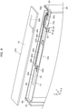
- FIG. 4 is an exploded perspective view of a portion in proximity to lower plate 24 of image display device 10 according to Embodiment 1.
- FIG. 5 is a plan view of controller 16 of image display device 10 according to Embodiment 1.
- FIG. 6 is a cross-sectional view taken along line VI-VI in FIG. 5 .
- FIG. 5 omits illustration of cover 34 and the like and illustrates the lower edge of display panel 12 as a chained double-dashed line.
- image display device 10 includes display panel 12, housing 14, and controller 16.
- Image display device 10 is an image display device connectable to Wi-Fi (registered trademark) and the like via antenna unit 54 (to be described later) disposed in proximity to the lower edge of display panel 12.
- Wi-Fi registered trademark
- antenna unit 54 to be described later
- display panel 12 is a display device switchable between an image display mode in which an image is displayed on front surface 13 of display panel 12 and a transmissive mode in which display panel 12 is in a transmissive state where each of objects behind image display panel 12 is visible in the front view of display panel 12.
- Display panel 12 has a rectangular shape in the front view.
- display panel 12 is an organic electro-luminescent (EL) panel, and includes front glass plate 18 and organic light-emitting diode (OLED) panel 20 disposed behind front glass plate 18.
- organic EL elements each of which includes an EL layer and transparent electrodes sandwiching the EL layer, are disposed in a matrix in OLED panel 20.
- the region of OLED panel 20 where an image (including background image) is not displayed has light transmitting properties to the extent generally referred to as transparent.
- the "image" displayed on display panel 12 may be any of a still image or a moving image, or may be video content including both the still image and the moving image.
- Display panel 12 becomes, for example, as illustrated in FIG. 1 , a first transmissive mode, in which objects 200 behind display panel 12 are visible, by not displaying an image on display panel 12. Moreover, as illustrated in FIG. 2 , display panel 12 becomes an image display mode by displaying image 202 on the entire region of the image display region of display panel 12. Moreover, as illustrated in FIG. 3 , display panel 12 becomes a second transmissive mode in which objects 200 behind display panel 12 are visible while partial images 204 are displayed by displaying partial images 204 in a portion of the image display region of display panel 12. Moreover, display panel 12 may include, for example, an optical component, such as an anti-reflection film and a light adjusting panel, in addition to the above described structural elements.
- an optical component such as an anti-reflection film and a light adjusting panel
- front surface 13 of display panel 12 is the front surface of front glass plate 18.
- Display panel 12 does not have to include front glass plate 18.
- the front surface of display panel 12 is the front surface of OLED panel 20.
- housing 14 is disposed along the edge of display panel 12, and supports display panel 12. Housing 14 supports display panel 12 such that display panel 12 tilts slightly rearward.
- Housing 14 includes upper plate 22 disposed along the upper edge of display panel 12, lower plate 24 disposed along the lower edge of display panel 12, left plate 26 disposed along the left edge of display panel 12, and right plate 28 disposed along the right edge of display panel 12.
- Each of upper plate 22, lower plate 24, left plate 26, and right plate 28 has a plate shape.
- Each of upper plate 22, lower plate 24, left plate 26, and right plate 28 protrudes forward and rearward relative to display panel 12.
- Upper plate 22 and lower plate 24 are disposed parallel to each other, and left plate 26 and right plate 28 are disposed parallel to each other.
- Upper plate 22 includes a groove (not illustrated) recessed upward. The upper edge of display panel 12 is accommodated in the groove.
- lower plate 24 includes bottom plate 30, front wall 32, and cover 34.
- Bottom plate 30 extends in the left-right direction. Controller 16 and the like are disposed on bottom plate 30.
- Bottom plate 30 includes notch 31 formed by notching the front edge of bottom plate 30. Notch 31 is recessed rearward in the front edge of bottom plate 30, and extends in the left-right direction. Notch 31 is positioned to the right of the central portion of bottom plate 30 in the left-right direction.
- Lid 40 (to be described later) is disposed on notch 31.
- Front wall 32 includes main body 35, accommodation unit 36, notch 38, and lid 40.
- Main body 35 extends in the left-right direction along the lower edge of display panel 12 in front of the lower edge of display panel 12, and is fixed to the front edge of bottom plate 30. In such a manner, main body 35 is disposed so as to protrude forward relative to the lower edge of display panel 12. Main body 35 is positioned in front of front surface 13 of display panel 12, and overlaps display panel 12 in the front-back direction. Specifically, main body 35 is positioned in front of the lower edge of front surface 13 of display panel 12, and overlaps the lower edge of display panel 12 in the front-back direction.
- Accommodation unit 36 is a portion which accommodates antenna unit 54. Accommodation unit 36 is positioned to the right of the central portion of main body 35 in the left-right direction.
- Accommodation unit 36 is opened in the bottom surface of main body 35, that is, is opened downward, and is recessed upward.
- Accommodation unit 36 is positioned above notch 31, and extends in the left-right direction along notch 31.
- Accommodation unit 36 is positioned to the right of the central portion of display panel 12 in the left-right direction.
- Accommodation unit 36 is positioned in front of front surface 13 of display panel 12, and overlaps display panel 12 in the front-back direction.
- Accommodation unit 36 is positioned in front of the lower edge of front surface 13 of display panel 12, and overlaps the lower edge of display panel 12 in the front-back direction.
- Notch 38 is a portion through which electric wire 72 (to be described later) which connects antenna unit 54 and communication board 56 (to be described later) passes.
- Notch 38 is disposed behind accommodation unit 36 and is formed by notching main body 35.
- Lid 40 is a component which supports antenna unit 54 from below. Lid 40 extends in the left-right direction, and is disposed on accommodation unit 36 so as to cover opening 42 of accommodation unit 36. Lid 40 is attached to main body 35 by two bolts 44.
- Cover 34 is disposed above bottom plate 30 so as to cover controller 16 and the like. The front edge of cover 34 is disposed spaced apart from front wall 32 in the front-back direction. Lower plate 24 accommodates the lower edge of display panel 12 by inserting the lower edge of display panel 12 between front wall 32 and the front edge of cover 34.
- One or more objects 200 can be placed on the upper surface of cover 34.
- lower plate 24 When display panel 12 operates in a transmissive mode, the user is capable of viewing objects 200 placed on the upper surface of cover 34 via display panel 12.
- the elements housed in lower plate 24 are not limited to controller 16.
- a loudspeaker device, an exhaust fan, a television tuner, an optical disk player and the like which are not illustrated may be accommodated in lower plate 24.
- Left plate 26 connects the left edge of upper plate 22 and the left edge of lower plate 24.
- Left plate 26 includes a groove (not illustrated) recessed toward the left. The left edge of display panel 12 is accommodated in the groove.
- Right plate 28 connects the right edge of upper plate 22 and the right edge of lower plate 24.
- Right plate 28 includes groove 29 recessed toward the right. The right edge of display panel 12 is accommodated in groove 29.
- front wall 32 corresponds to a non-conductive component, and front wall 32 forms part of housing 14.
- controller 16 is accommodated in lower plate 24 to control the operation of display panel 12.
- Controller 16 includes power supply board 46, signal board 48, T-con board 50, two source boards 52, antenna unit 54, and communication board 56.
- Antenna unit 54 is disposed in front of the lower edge of display panel 12.
- Power supply board 46, signal board 48, T-con board 50, two source boards 52, and communication board 56 are disposed behind the lower edge of display panel 12.
- antenna unit 54 is disposed in front of the lower edge of front surface 13 of display panel 12.
- Power supply board 46, signal board 48, T-con board 50, two source boards 52, and communication board 56 are disposed behind the lower edge of front surface 13 of display panel 12.
- Power supply board 46 is connected to an external power supply (not illustrated) via electric wire 58, is connected to signal board 48 via electric wire 60, and is connected to T-con board 50 via electric wire 62. Power supply board 46 supplies power from the external power supply to signal board 48, T-con board 50, and the like. Power supply board 46 is positioned to the right of the central portion of bottom plate 30 in the left-right direction.
- Signal board 48 is connected to communication board 56 via electric wire 64 to transmit and receive signals to and from communication board 56.
- Signal board 48 is connected to T-con board 50 via electric wire 66 to transmit and receive signals to and from T-con board 50.
- Signal board 48 is positioned to the left of the central portion of bottom plate 30 in the left-right direction.
- T-con board 50 forms so-called a timing controller, and is connected to two source boards 52 via flexible printed boards 68.
- T-con board 50 generates various types of signals, such as a clock signal for distributing image data to be displayed on display panel 12 to each pixel included in display panel 12, and supplies the signals to source boards 52.
- T-con board 50 is positioned in the central portion of bottom plate 30 in the left-right direction.
- Two source boards 52 are connected to display panel 12 via flexible printed boards 70, to supply a signal from T-con board 50 to display panel 12.
- Two source boards 52 are disposed adjacent to each other, and in front of power supply board 46, signal board 48, T-con board 50, and communication board 56.
- Antenna unit 54 is connected to communication board 56 via electric wire 72.
- Antenna unit 54 transmits and receives radio waves used by communication board 56 and another communication apparatus (not illustrated) for performing communication in accordance with Wi-Fi (registered trademark) standard.
- Antenna unit 54 extends in the left-right direction, and has a plate shape.
- Antenna unit 54 is accommodated in accommodation unit 36 while projecting in the top-bottom direction, and is disposed in proximity to the lower edge of display panel 12.
- Antenna unit 54 is positioned to the right of the central portion of main body 35 in the left-right direction and is positioned to the right of the central portion of display panel 12 in the left-right direction.
- Antenna unit 54 is positioned in front of front surface 13 of display panel 12, and overlaps display panel 12 in the front-back direction. Specifically, antenna unit 54 is positioned in front of the lower edge of front surface 13 of display panel 12, and overlaps the lower edge of display panel 12 in the front-back direction. Antenna unit 54 is entirely positioned in front of the lower edge of front surface 13 of display panel 12. Antenna unit 54 is supported by lid 40 from below. The front, top, left, and right of antenna unit 54 are covered by main body 35, and the bottom of antenna unit 54 is covered by lid 40. Antenna unit 54 does not have to be entirely positioned in front of the lower edge of front surface 13 of display panel 12.
- antenna unit 54 may be positioned in front of the lower edge of front surface 13 of display panel 12.
- a conductive material such as metal can be used.
- antenna unit 54 includes a metal component and a resin which covers at least a portion of the metal component.
- Communication board 56 performs communication with another communication apparatus via antenna unit 54. Communication board 56 also transmits and receives a signal to and from signal board 48. Communication board 56 is positioned to the right of the central portion of bottom plate 30 in the left-right direction, and is positioned slightly closer to the central portion than the right edge of bottom plate 30 is. Communication board 56 is positioned to the right of the central portion of display panel 12 and antenna unit 54 in the left-right direction.
- image display device 10 includes: display panel 12 which displays an image on front surface 13 of display panel 12; antenna unit 54 disposed in front of front surface 13 of display panel 12; and front wall 32 which accommodates antenna unit 54.
- antenna unit 54 is positioned in front of front surface 13 of display panel 12. Accordingly, for example, even when image display panel 10 is disposed near the wall, it is possible to prevent the radio waves received by antenna unit 54 from being blocked by the wall. This leads to improved reception performance of antenna unit 54. Moreover, antenna unit 54 is accommodated in accommodation unit 36 of front wall 32. Accordingly, compared with the case where antenna unit 54 is accommodated in a conductive component, it is possible to prevent the sensitivity of antenna unit 54 from decreasing. This leads to improved reception performance of antenna unit 54. Moreover, this prevents antenna unit 54 from being seen by the user, and improves the appearance of image display device 10. In addition, it prevents the user from directly touching antenna unit 54, which leads to improved safety.
- Image display device 10 further includes communication board 56 which is disposed behind display panel 12 and which is capable of performing communication with antenna unit 54.
- communication board 56 is disposed behind display panel 12. Accordingly, it is possible to improve the reception performance of antenna unit 54 while preventing communication board 56 from being seen by the user in front of display panel 12.
- front wall 32 includes accommodation unit 36 which is opened downward and which accommodates antenna unit 54, and lid 40 which is disposed on accommodation unit 36.
- Image display device 10 further includes housing 14 disposed along the edge of display panel 12. Front wall 32 forms part of housing 14.
- front wall 32 forms part of housing 14.
- antenna unit 54 can be accommodated without separately providing a component for accommodating antenna unit 54.
- antenna unit 54 is disposed so as to overlap display panel 12 in the front-back direction.
- antenna unit 54 does not overlap display panel 12 in the front-back direction, it is possible to improve the reception performance of antenna unit 54 while preventing the size of image display device 10 from increasing in the top-bottom direction and the left-right direction.
- front wall 32 is disposed along the lower edge of display panel 12, and protrudes forward relative to display panel 12.
- antenna unit 54 can be positioned in proximity to the lower edge of display panel 12. Hence, it is possible to improve the reception performance of antenna unit 54 while preventing the image displayed on display panel 12 from becoming difficult to be viewed due to overlapping with antenna unit 54.
- FIG. 7 is an external perspective view of a state of image display device 10a according to Embodiment 2 when operating in a first transmissive mode.
- FIG. 8 is an exploded perspective view of a portion in proximity to upper plate 22a of image display device 10a according to Embodiment 2.
- FIG. 9 is a plan view of controller 16a of image display device 10a according to Embodiment 2.
- FIG. 10 is a cross-sectional view taken along line X-X in FIG. 9 . Note that illustration of source boards 52a and the like is omitted in FIG. 8 in order to prevent the drawing from becoming complicated.
- FIG. 9 omits illustration of upper plate 22a and the like and illustrates the upper edge of display panel 12 as a chained double-dashed line.
- image display device 10a includes: display panel 12; housing 14a; controller 16a; and illumination unit 74.
- Image display device 10a is an image display device connectable to Wi-Fi (registered trademark) or the like via antenna unit 54 disposed in proximity to the upper edge of display panel 12.
- Wi-Fi registered trademark
- antenna unit 54 disposed in proximity to the upper edge of display panel 12.
- housing 14a includes upper plate 22a, lower plate 24a, left plate 26, and right plate 28.
- Each of upper plate 22a, lower plate 24a, left plate 26, and right plate 28 protrudes forward and rearward relative to display panel 12.
- upper plate 22a includes main body 75 and groove 76.
- Main body 75 extends in the left-right direction, and is disposed along the upper edge of display panel 12. Main body 75 protrudes forward and rearward relative to display panel 12. Main body 75 is positioned in front of front surface 13 of display panel 12, and overlaps display panel 12 in the front-back direction. Specifically, main body 75 is positioned in front of the upper edge of front surface 13 of display panel 12, and overlaps the upper edge of display panel 12 in the front-back direction.
- Groove 76 is a groove in which the upper edge of display panel 12 is accommodated. Groove 76 is opened in the bottom surface of main body 75, that is, opened downward and recessed upward.
- Groove 76 extends along the upper edge of display panel 12 in the left-right direction.
- Upper plate 22a includes accommodation unit 36a, groove 38a, and lid 40.
- Accommodation unit 36a is a portion for accommodating antenna unit 54.
- Accommodation unit 36a is positioned to the right of the central portion of main body 75 in the left-right direction.
- Accommodation unit 36a is opened in the bottom surface of main body 75, that is, is opened downward, and is recessed upward.
- Accommodation unit 36a extends in the left-right direction.
- Accommodation unit 36a is positioned to the right of the central portion of display panel 12 in the left-right direction.
- Accommodation unit 36a is positioned in front of front surface 13 of display panel 12, and overlaps display panel 12 in the front-back direction.
- accommodation unit 36a is positioned in front of the upper edge of front surface 13 of display panel 12, and overlaps the upper edge of display panel 12 in the front-back direction.
- Groove 38a is a portion through which electric wire 72a (to be described later) which connects antenna unit 54 and communication board 56a (to be described later) passes.
- Groove 38a is opened in the bottom surface of main body 75, that is, is opened downward, and is recessed upward.
- Groove 38a is in communication with accommodation unit 36a.
- Groove 38a extends rearward from accommodation unit 36a, and then extends toward the right.
- Lid 40 is a component which supports antenna unit 54 from below, and is disposed on accommodation unit 36a. Lid 40 is attached to main body 75 by two bolts 44.
- Lower plate 24a includes a groove (not illustrated) recessed downward. The lower edge of display panel 12 is accommodated in the groove. Detailed descriptions of left plate 26 and right plate 28 are omitted by referring to the descriptions given in Embodiment 1.
- main body 75, lid 40, lower plate 24a, left plate 26, and right plate 28 for example, non-conductive materials such as wood or resin can be used.
- upper plate 22a corresponds to the non-conductive component and upper plate 22a forms part of housing 14.
- controller 16a is supported by upper plate 22a on the lower surface side of upper plate 22a, and controls the operations of display panel 12 and illumination unit 74.
- Controller 16a includes power supply board 46a, signal board 48a, T-con board 50a, two source boards 52a, antenna unit 54, communication board 56a, and support 77.
- power supply board 46a, signal board 48a, T-con board 50a, and two source boards 52a are omitted by referring to the descriptions given in Embodiment 1.
- Antenna unit 54 is connected to communication board 56a via electric wire 72a.
- Antenna unit 54 transmits and receives radio waves used by communication board 56 and another communication apparatus (not illustrated) for performing communication in accordance with Wi-Fi (registered trademark) standard.
- Antenna unit 54 extends in the left-right direction, and has a plate shape.
- Antenna unit 54 is accommodated in accommodation unit 36a while projecting in the top-bottom direction, and is disposed in proximity to the upper edge of display panel 12.
- Antenna unit 54 is positioned to the right of the central portion of main body 75 in the left-right direction and is positioned to the right of the central portion of display panel 12 in the left and right direction.
- Antenna unit 54 is positioned in front of front surface 13 of display panel 12.
- antenna unit 54 is positioned in front of the upper edge of front surface 13 of display panel 12. Antenna unit 54 is entirely positioned in front of the upper edge of front surface 13 of display panel 12. Antenna unit 54 is supported by lid 40 from below. The front, top, left, and right of antenna unit 54 are covered by main body 75, and the bottom of antenna unit 54 is covered by lid 40.
- antenna unit 54 only has to be positioned at least in front of the upper edge of front surface 13 of display panel 12, and may be positioned behind the lower edge of front surface 13 of display panel 12.
- Antenna unit 54 does not have to be entirely positioned in front of the upper edge of front surface 13 of display panel 12. For example, at least a portion of antenna unit 54 may be positioned in front of the upper edge of front surface 13 of display panel 12. Moreover, antenna unit 54 may overlap display panel 12 in the front-back direction. Specifically, antenna unit 54 may overlap the upper edge of display panel 12 in the front-back direction. As the material of antenna unit 54, for example, a conductive material such as metal can be used. Specifically, for example, antenna unit 54 includes a metal component and a resin which covers at least a portion of the metal component.
- Communication board 56a performs communication with another communication apparatus via antenna unit 54. Communication board 56a also transmits and receives a signal to and from signal board 48a. Communication board 56a is positioned to the right of the central portion of support 77 in the left-right direction, and is positioned slightly closer to the central portion than the right edge of support 77 is. Communication board 56a is positioned to the right of the central portion of display panel 12 and is positioned to the right of antenna unit 54 in the left-right direction.
- Support 77 extends in the left-right direction, is attached to the bottom surface of upper plate 22a, and connects left plate 26 and right plate 28.
- Support 77 includes bottom portion 78, left portion 80, right portion 82, and back portion 84.
- Bottom portion 78 extends in the left-right direction, has a plate shape, and is disposed substantially parallel to upper plate 22a.
- the front edge of bottom portion 78 has a cross-section with a substantial reverse U shape (see FIG. 10 ).
- Illumination unit 74 is supported by the front edge of bottom portion 78.
- Left portion 80 protrudes upward from the left edge of bottom portion 78, and is disposed along left plate 26.
- Left portion 80 is fixed to left plate 26 by bolts (not illustrated).
- Right portion 82 protrudes upward from the right edge of bottom portion 78, and is disposed along right plate 28.
- Right portion 82 is fixed to right plate 28 by bolts (not illustrated).
- Left portion 80 is fixed to left plate 26 and right portion 82 is fixed to right plate 28, so that support 77 connects left plate 26 and right plate 28.
- Back portion 84 protrudes upward from the rear edge of bottom portion 78.
- the upper edge of rear portion 84 is folded rearward, and is fixed to upper plate 22a by bolts (not illustrated).
- a conductive material such as metal can be used as the material of support 77.
- illumination unit 74 is disposed on the front edge of bottom portion 78 of support 77, and is electrically connected to controller 16a by electric wires (not illustrated).
- minute light shielding elements such as organic EL elements and liquid crystals, are dispersed in display panel 12.
- the light transmittance of display panel 12 is, for example, 40% to 50% approximately. Accordingly, for example, when image display device 10a is placed in a relatively dark environment, the user may fail to clearly view objects 200 behind display panel 12. However, objects 200 behind display panel 12 can be illuminated by the light emitted by illumination unit 74.
- Illumination unit 74 is embedded in the front edge of bottom portion 78. Accordingly, when display panel 12 is turned into a transmissive state, it is possible to prevent the light emitted from illumination unit 74 from directly entering the eyes of the user in front of image display device 10a. Illumination unit 74 includes board 86 elongated in the left-right direction and a plurality of LED elements 88 which are mounted on board 86 and which emit light. One or more objects 200 placed on lower plate 24a are illuminated by illumination unit 74 configured as above.
- upper plate 22a is disposed along the upper edge of display panel 12, and protrudes forward relative to display panel 12.
- antenna unit 54 can be positioned in proximity to the upper edge of display panel 12. Hence, it is possible to improve the reception performance of antenna unit 54 while preventing the image displayed on display panel 12 from becoming difficult to be viewed due to overlapping with antenna unit 54.
- display panel 12 is switchable between an image display mode in which an image is displayed on front surface 13 and a transmissive mode in which display panel 12 is in a transmissive state where an object behind display panel 12 is visible in a front view of display panel 12.
- display panel 12b may be a liquid crystal panel or the like which is not capable of switching between the image display mode and the transmissive mode.
- antenna unit 54 only has to be positioned in front of the front surface of display panel 12b (see FIG. 11 ).
- antenna unit 54 is accommodated in lower plate 24 disposed along the lower edge of display panel 12 and where antenna unit 54 is accommodated in upper plate 22a disposed along the upper edge of display panel 12.
- antenna unit 54 may be accommodated in left plate 26 disposed along the left edge of display panel 12, or may be accommodated in right plate 28 disposed along the right edge of display panel 12.
- antenna unit 54 and accommodation unit 36 are positioned to the right of the central portion of display panel 12 in the left-right direction and where antenna unit 54 and accommodation unit 36a are positioned to the right of the central portion of display panel 12 in the left-right direction.
- the present disclosure is not limited to such examples.
- the antenna unit and the accommodation unit may be positioned in the central portion of display panel 12 in the left-right direction, or may be positioned to the left of the central portion of display panel 12 in the left-right direction.
- housing 14 includes upper plate 22, lower plate 24, left plate 26, and right plate 28 each of which has a plate shape and where housing 14a includes upper plate 22a, lower plate 24a, left plate 26, and right plate 28 each of which has a plate shape.
- the housing may include an upper frame, a lower frame, a left frame, and a right frame each of which has a prism shape.
- housing 14 supports display panel 12 so that display panel 12 tilts slightly rearward.
- the present disclosure is not limited to such an example.
- the housing may support display panel 12 such that display panel 12 does not tilt in the front-back direction.
- antenna unit 54 has a plate shape.
- the present disclosure is not limited to such an example.
- the antenna unit may have a bar shape, cylinder shape, or columnar shape.
- the antenna unit may have a meander shape.
- the structural elements described in the accompanying drawings and detailed description may include not only structural elements which are essential for solving the problem but also structural elements which are not essential for solving the problem but are provided for illustrating the technique. Therefore, the non-essential structural elements described in the attached drawings and/or the detailed description should not be instantly acknowledged to be essential structural elements.
- the present disclosure is applicable to an image display device, such as a television receiver, a monitor display, or a digital signage.
Landscapes
- Engineering & Computer Science (AREA)
- Theoretical Computer Science (AREA)
- Physics & Mathematics (AREA)
- General Engineering & Computer Science (AREA)
- Computer Hardware Design (AREA)
- Human Computer Interaction (AREA)
- General Physics & Mathematics (AREA)
- Electromagnetism (AREA)
- Power Engineering (AREA)
- Multimedia (AREA)
- Signal Processing (AREA)
- Devices For Indicating Variable Information By Combining Individual Elements (AREA)
Applications Claiming Priority (2)
| Application Number | Priority Date | Filing Date | Title |
|---|---|---|---|
| JP2019081220 | 2019-04-22 | ||
| PCT/JP2020/017119 WO2020218266A1 (ja) | 2019-04-22 | 2020-04-20 | 画像表示装置 |
Publications (2)
| Publication Number | Publication Date |
|---|---|
| EP3962071A1 true EP3962071A1 (de) | 2022-03-02 |
| EP3962071A4 EP3962071A4 (de) | 2022-05-11 |
Family
ID=72942769
Family Applications (1)
| Application Number | Title | Priority Date | Filing Date |
|---|---|---|---|
| EP20794043.8A Pending EP3962071A4 (de) | 2019-04-22 | 2020-04-20 | Bildanzeigevorrichtung |
Country Status (5)
| Country | Link |
|---|---|
| US (1) | US12228979B2 (de) |
| EP (1) | EP3962071A4 (de) |
| JP (1) | JP7457988B2 (de) |
| CN (1) | CN112673623B (de) |
| WO (1) | WO2020218266A1 (de) |
Families Citing this family (6)
| Publication number | Priority date | Publication date | Assignee | Title |
|---|---|---|---|---|
| JP1723568S (ja) * | 2020-06-24 | 2022-08-31 | 巻取り式ディスプレイ付きテレビジョン | |
| USD1016769S1 (en) * | 2020-07-16 | 2024-03-05 | Lg Electronics Inc. | Television with rollable display |
| USD1016768S1 (en) * | 2020-07-16 | 2024-03-05 | Lg Electronics Inc. | Television assembly with rollable display and drawers |
| JP1732741S (ja) * | 2020-07-16 | 2022-12-21 | 巻取り式ディスプレイ付きテレビジョン | |
| EP4280034A1 (de) * | 2022-05-19 | 2023-11-22 | Aito BV | Haptisches berührungsmodul und ein verfahren zum herstellen des haptischen berührungsmoduls |
| USD1074630S1 (en) * | 2023-11-24 | 2025-05-13 | Lg Electronics Inc. | Television receiver |
Family Cites Families (28)
| Publication number | Priority date | Publication date | Assignee | Title |
|---|---|---|---|---|
| JP2972702B2 (ja) * | 1998-03-17 | 1999-11-08 | 静岡日本電気株式会社 | ペン入力型携帯情報端末機 |
| JP2003060422A (ja) * | 2001-08-09 | 2003-02-28 | Matsushita Electric Ind Co Ltd | ディスプレイ−アンテナ一体型構造体、通信装置 |
| JP2003143030A (ja) * | 2001-11-05 | 2003-05-16 | Citizen Watch Co Ltd | 携帯型情報端末 |
| US6842335B1 (en) * | 2001-11-21 | 2005-01-11 | Palmone, Inc. | Multifunctional cover integrated into sub-panel of portable electronic device |
| US6879293B2 (en) * | 2002-02-25 | 2005-04-12 | Tdk Corporation | Antenna device and electric appliance using the same |
| JP4088180B2 (ja) * | 2003-03-14 | 2008-05-21 | 株式会社東芝 | 電子機器 |
| TWM289264U (en) * | 2005-08-10 | 2006-04-01 | Compal Electronics Inc | Display frame having antenna |
| JP4365365B2 (ja) | 2005-10-31 | 2009-11-18 | シャープ株式会社 | 無線装置を備えた機器および無線装置の収納構造 |
| TW200735458A (en) * | 2006-03-14 | 2007-09-16 | Mitac Technology Corp | Built-in antenna structure |
| US20080258990A1 (en) * | 2007-04-17 | 2008-10-23 | Burrell Dennis A | Parasitically-coupled surface-attachable antenna systems and related methods |
| JP4973311B2 (ja) * | 2007-05-16 | 2012-07-11 | ソニー株式会社 | 電子機器 |
| JP2009094864A (ja) | 2007-10-10 | 2009-04-30 | Univ Of Electro-Communications | テレビジョン装置 |
| JP2009211372A (ja) * | 2008-03-04 | 2009-09-17 | Daito Electron Co Ltd | 液晶表示装置 |
| JP5077051B2 (ja) | 2008-04-28 | 2012-11-21 | 株式会社Jvcケンウッド | アンテナ取付構造および車載用機器 |
| JP5235121B2 (ja) * | 2008-10-07 | 2013-07-10 | パナソニック株式会社 | 情報処理装置 |
| CN201893384U (zh) * | 2010-09-16 | 2011-07-06 | 昆山维信诺显示技术有限公司 | 一种有机电致发光器件,显示器及应用该显示器的移动通信设备 |
| JP2013038650A (ja) * | 2011-08-09 | 2013-02-21 | Nikon Corp | 電子機器 |
| JP5079922B1 (ja) * | 2011-08-23 | 2012-11-21 | シャープ株式会社 | ブラケット、取付システムおよび型紙 |
| JP5175968B1 (ja) * | 2011-10-28 | 2013-04-03 | 株式会社東芝 | スタンドおよび電子機器 |
| PL2800360T3 (pl) * | 2011-12-27 | 2021-01-25 | Saturn Licensing Llc | Urządzenie podłączeniowe |
| KR101848628B1 (ko) * | 2012-05-25 | 2018-04-13 | 삼성전자주식회사 | 디스플레이 장치 |
| KR20150033398A (ko) | 2013-09-24 | 2015-04-01 | 삼성전자주식회사 | 디스플레이 장치 |
| WO2016092801A1 (ja) * | 2014-12-08 | 2016-06-16 | パナソニックIpマネジメント株式会社 | アンテナ及び電気機器 |
| KR102466002B1 (ko) * | 2016-04-19 | 2022-11-11 | 삼성전자주식회사 | 안테나를 포함하는 전자 장치 |
| JP2018040852A (ja) * | 2016-09-05 | 2018-03-15 | シャープ株式会社 | 表示装置およびテレビジョン受信機 |
| WO2018139111A1 (ja) | 2017-01-26 | 2018-08-02 | シャープ株式会社 | ヘッドマウントディスプレイおよびヘッドマウントディスプレイシステム |
| KR102388342B1 (ko) * | 2017-09-07 | 2022-04-20 | 삼성전자주식회사 | 안테나를 포함하는 전자 장치 |
| CN108736128A (zh) * | 2018-06-29 | 2018-11-02 | 珠海市魅族科技有限公司 | 终端设备及终端设备的控制方法 |
-
2020
- 2020-04-20 WO PCT/JP2020/017119 patent/WO2020218266A1/ja not_active Ceased
- 2020-04-20 US US17/273,691 patent/US12228979B2/en active Active
- 2020-04-20 EP EP20794043.8A patent/EP3962071A4/de active Pending
- 2020-04-20 JP JP2021516115A patent/JP7457988B2/ja active Active
- 2020-04-20 CN CN202080005068.2A patent/CN112673623B/zh active Active
Also Published As
| Publication number | Publication date |
|---|---|
| JP7457988B2 (ja) | 2024-03-29 |
| WO2020218266A1 (ja) | 2020-10-29 |
| US20210311533A1 (en) | 2021-10-07 |
| EP3962071A4 (de) | 2022-05-11 |
| JPWO2020218266A1 (de) | 2020-10-29 |
| US12228979B2 (en) | 2025-02-18 |
| CN112673623B (zh) | 2024-06-11 |
| CN112673623A (zh) | 2021-04-16 |
Similar Documents
| Publication | Publication Date | Title |
|---|---|---|
| EP3962071A1 (de) | Bildanzeigevorrichtung | |
| CN109743426B (zh) | 电子装置 | |
| EP3598217B1 (de) | Anzeigevorrichtung | |
| US20090147155A1 (en) | Digital photo frame | |
| US9568756B2 (en) | Display device | |
| KR102460231B1 (ko) | 백라이트 유닛 및 이를 포함하는 액정 표시 장치 | |
| US20200225539A1 (en) | Display device | |
| US10965797B2 (en) | Terminal | |
| EP2816393B1 (de) | Flüssigkristalltafelanordnung und Flüssigkristallanzeigevorrichtung damit | |
| US20190394318A1 (en) | Terminal | |
| JP2014127900A (ja) | 表示装置 | |
| US10921647B2 (en) | Display device | |
| US10928676B2 (en) | Display device | |
| EP3949809B1 (de) | Bildanzeigevorrichtung | |
| US9910462B2 (en) | Display module and electronic device including the same | |
| KR20130074794A (ko) | 표시장치 | |
| EP3779936B1 (de) | Bildanzeigevorrichtung | |
| US11316960B2 (en) | Electronic apparatus comprising display panel including at least one hole | |
| US20150022759A1 (en) | Display with Radioluminescent Backlight Unit | |
| KR20180025776A (ko) | 디스플레이 장치 | |
| US20120194759A1 (en) | Liquid crystal module and method for assembling thereof | |
| JP5197822B2 (ja) | 電子機器 | |
| KR102091113B1 (ko) | 슬림형 대화면 시현기 | |
| JP2008152086A (ja) | 表示装置及び電子機器 |
Legal Events
| Date | Code | Title | Description |
|---|---|---|---|
| STAA | Information on the status of an ep patent application or granted ep patent |
Free format text: STATUS: THE INTERNATIONAL PUBLICATION HAS BEEN MADE |
|
| PUAI | Public reference made under article 153(3) epc to a published international application that has entered the european phase |
Free format text: ORIGINAL CODE: 0009012 |
|
| STAA | Information on the status of an ep patent application or granted ep patent |
Free format text: STATUS: REQUEST FOR EXAMINATION WAS MADE |
|
| 17P | Request for examination filed |
Effective date: 20211102 |
|
| AK | Designated contracting states |
Kind code of ref document: A1 Designated state(s): AL AT BE BG CH CY CZ DE DK EE ES FI FR GB GR HR HU IE IS IT LI LT LU LV MC MK MT NL NO PL PT RO RS SE SI SK SM TR |
|
| A4 | Supplementary search report drawn up and despatched |
Effective date: 20220408 |
|
| RIC1 | Information provided on ipc code assigned before grant |
Ipc: H01Q 1/22 20060101ALI20220404BHEP Ipc: G06F 1/16 20060101ALI20220404BHEP Ipc: H04N 5/64 20060101AFI20220404BHEP |
|
| DAV | Request for validation of the european patent (deleted) | ||
| DAX | Request for extension of the european patent (deleted) | ||
| STAA | Information on the status of an ep patent application or granted ep patent |
Free format text: STATUS: EXAMINATION IS IN PROGRESS |
|
| 17Q | First examination report despatched |
Effective date: 20240215 |