EP3962190A1 - Verfahren zur steuerung der datenübertragung in einem funkkommunikationssystem - Google Patents
Verfahren zur steuerung der datenübertragung in einem funkkommunikationssystem Download PDFInfo
- Publication number
- EP3962190A1 EP3962190A1 EP20192965.0A EP20192965A EP3962190A1 EP 3962190 A1 EP3962190 A1 EP 3962190A1 EP 20192965 A EP20192965 A EP 20192965A EP 3962190 A1 EP3962190 A1 EP 3962190A1
- Authority
- EP
- European Patent Office
- Prior art keywords
- hopping
- frequency
- user equipment
- user
- equipment
- Prior art date
- Legal status (The legal status is an assumption and is not a legal conclusion. Google has not performed a legal analysis and makes no representation as to the accuracy of the status listed.)
- Withdrawn
Links
Images




Classifications
-
- H—ELECTRICITY
- H04—ELECTRIC COMMUNICATION TECHNIQUE
- H04W—WIRELESS COMMUNICATION NETWORKS
- H04W72/00—Local resource management
-
- H—ELECTRICITY
- H04—ELECTRIC COMMUNICATION TECHNIQUE
- H04B—TRANSMISSION
- H04B1/00—Details of transmission systems, not covered by a single one of groups H04B3/00 - H04B13/00; Details of transmission systems not characterised by the medium used for transmission
- H04B1/69—Spread spectrum techniques
- H04B1/713—Spread spectrum techniques using frequency hopping
- H04B1/7136—Arrangements for generation of hop frequencies, e.g. using a bank of frequency sources, using continuous tuning or using a transform
-
- H—ELECTRICITY
- H04—ELECTRIC COMMUNICATION TECHNIQUE
- H04B—TRANSMISSION
- H04B1/00—Details of transmission systems, not covered by a single one of groups H04B3/00 - H04B13/00; Details of transmission systems not characterised by the medium used for transmission
- H04B1/69—Spread spectrum techniques
- H04B1/713—Spread spectrum techniques using frequency hopping
- H04B1/7143—Arrangements for generation of hop patterns
-
- H—ELECTRICITY
- H04—ELECTRIC COMMUNICATION TECHNIQUE
- H04L—TRANSMISSION OF DIGITAL INFORMATION, e.g. TELEGRAPHIC COMMUNICATION
- H04L1/00—Arrangements for detecting or preventing errors in the information received
- H04L1/12—Arrangements for detecting or preventing errors in the information received by using return channel
- H04L1/16—Arrangements for detecting or preventing errors in the information received by using return channel in which the return channel carries supervisory signals, e.g. repetition request signals
- H04L1/18—Automatic repetition systems, e.g. Van Duuren systems
- H04L1/1812—Hybrid protocols; Hybrid automatic repeat request [HARQ]
-
- H—ELECTRICITY
- H04—ELECTRIC COMMUNICATION TECHNIQUE
- H04L—TRANSMISSION OF DIGITAL INFORMATION, e.g. TELEGRAPHIC COMMUNICATION
- H04L5/00—Arrangements affording multiple use of the transmission path
- H04L5/0001—Arrangements for dividing the transmission path
- H04L5/0003—Two-dimensional division
- H04L5/0005—Time-frequency
- H04L5/0007—Time-frequency the frequencies being orthogonal, e.g. OFDM(A) or DMT
- H04L5/0012—Hopping in multicarrier systems
-
- H—ELECTRICITY
- H04—ELECTRIC COMMUNICATION TECHNIQUE
- H04W—WIRELESS COMMUNICATION NETWORKS
- H04W36/00—Hand-off or reselection arrangements
- H04W36/08—Reselecting an access point
-
- H—ELECTRICITY
- H04—ELECTRIC COMMUNICATION TECHNIQUE
- H04W—WIRELESS COMMUNICATION NETWORKS
- H04W72/00—Local resource management
- H04W72/04—Wireless resource allocation
- H04W72/044—Wireless resource allocation based on the type of the allocated resource
- H04W72/0453—Resources in frequency domain, e.g. a carrier in FDMA
-
- H—ELECTRICITY
- H04—ELECTRIC COMMUNICATION TECHNIQUE
- H04B—TRANSMISSION
- H04B1/00—Details of transmission systems, not covered by a single one of groups H04B3/00 - H04B13/00; Details of transmission systems not characterised by the medium used for transmission
- H04B1/69—Spread spectrum techniques
- H04B1/713—Spread spectrum techniques using frequency hopping
- H04B1/7136—Arrangements for generation of hop frequencies, e.g. using a bank of frequency sources, using continuous tuning or using a transform
- H04B2001/71362—Arrangements for generation of hop frequencies, e.g. using a bank of frequency sources, using continuous tuning or using a transform using a bank of frequency sources
-
- H—ELECTRICITY
- H04—ELECTRIC COMMUNICATION TECHNIQUE
- H04B—TRANSMISSION
- H04B1/00—Details of transmission systems, not covered by a single one of groups H04B3/00 - H04B13/00; Details of transmission systems not characterised by the medium used for transmission
- H04B1/69—Spread spectrum techniques
- H04B1/713—Spread spectrum techniques using frequency hopping
- H04B1/715—Interference-related aspects
- H04B2001/7154—Interference-related aspects with means for preventing interference
-
- H—ELECTRICITY
- H04—ELECTRIC COMMUNICATION TECHNIQUE
- H04B—TRANSMISSION
- H04B2201/00—Indexing scheme relating to details of transmission systems not covered by a single group of H04B3/00 - H04B13/00
- H04B2201/69—Orthogonal indexing scheme relating to spread spectrum techniques in general
- H04B2201/713—Frequency hopping
Definitions
- the present invention relates to a method for operating a base station transceiver of a cellular radio communication system in controlling transmission of a radio signal to a user equipment, to a controller device for controlling transmission of a radio signal from a base station transceiver of a cellular radio communication system to a user equipment, to a base station transceiver for use in a cellular radio communication system, and to a method for operating a user equipment of a cellular radio communication system in controlling reception of a radio signal from a base station transceiver.
- hopping schemes are frequently used for transmission of a radio signal from a base station transceiver to a user equipment.
- frequency sub-bands of a downlink frequency band used for the transmission are frequently changed according to a hopping scheme known to both the base station transceiver and the user equipment to reduce the effect of sources of interference on the transmission.
- Different hopping schemes are already known in the prior art. Performing hopping based on a pre-known sequence has the advantage of avoiding instantaneous signalling during execution of hopping sequence.
- WO 2018/073812 A1 describes a method in a wireless communication network comprises determining a frequency hopping sequence for communication between a wireless device and a network node.
- the frequency hopping sequence used is a function of a first hopping sequence and a second hopping sequence.
- the first hopping sequence has a first frequency step size and a first sequence length
- the second hopping sequence has a second frequency step size and a second sequence length.
- the first frequency step size is greater than the second frequency step size.
- the method of WO 2018/073812 A1 comprises communicating on frequencies selected according to the determined frequency hopping sequence.
- the objective of providing an improved hopping scheme is achieved, according to first aspect of the invention, by a method for operating a base station transceiver described in claim 1.
- the invention is formed by a controller device for a base station transceiver, and a base station transceiver according to claim 12 and 15, respectively.
- the invention is formed by a method for operating a user equipment according to claim 16.
- the invention is formed by a computer program for controlling a base station transceiver and a computer program for controlling a user equipment according to claims 21 and 22.
- the method according to the first aspect of the invention is concerned with operating a base station transceiver of a cellular radio communication system in controlling transmission of a radio signal to a user equipment.
- the method comprises determining frequency-hopping control information.
- the frequency-hopping control information is indicative of a hopping-frequency set of frequency sub-bands of a downlink frequency band of a downlink channel of the cellular radio communication system, which are to be used for transmission of consecutive radio signal segments of the radio signal to the user equipment.
- the frequency-hopping control information is indicative of a hopping time order of the frequency sub-bands of the hopping frequency set, which is to be used for the transmission of the consecutive radio signal segments of the radio signal to the user equipment.
- determining the frequency-hopping control information comprises
- the invention is based on the recognition that hopping schemes are very efficient to reduce the effect of sources of interference on the transmission.
- Certain environments in which the base station transceiver and the user equipment are used contain sources of interference that affect transmissions at one of more frequencies.
- hopping schemes are used in which consecutive radio signal segments of the radio signal are transmitted according to a hopping time order using a plurality of frequency sub-bands of the downlink frequency band of the downlink channel of the cellular radio communication system.
- the invention comprises the recognition that the described positive effect of given hopping schemes can be improved by taking into account any limitation of the set of suitable frequency sub-bands that is individual limitations for a given user equipment.
- the method of the present invention also comprises ascertaining user-equipment hopping-limitation information that is indicative of one or more of the frequency sub-bands of the downlink frequency band that are to be excluded from the hopping-frequency set, and using the user-equipment hopping-limitation information in determining the hopping frequency set.
- the reception performance can also suffer from internal sources of interference in the user equipment, also referred to as self-interference.
- wireless receiver modules nowadays are in close proximity to other modules inside a compact casing of a user equipment.
- DC-DC converters in particular switched-mode converters, or memory modules can act as internal sources of interference. Effects of this kind are typically known on the side of the manufacturer of the user equipment to be present in operation of a given user equipment.
- the present invention makes such information available to the base station transceiver for the control of the hopping scheme to be used in communication with a given user equipment.
- the effect of internal sources of self-interference can be decreased by excluding those frequencies that due to such self-interference exhibit decreased reception performance from the hopping-frequency set, using the user-equipment hopping-limitation information.
- the given example is non-limiting in the sense that any limitation known to apply for a given user equipment at the time of determining the frequency-hopping control information at the current location of the user equipment can be provided as user-equipment hopping-limitation information.
- the base station transceiver ascertains the user-equipment hopping-limitation information from different sources.
- ascertaining the user-equipment hopping-limitation information comprises receiving the user-equipment hopping-limitation information from the user equipment.
- This embodiment is particularly advantageous in that individual user-equipment hopping-limitation information is maintained directly at and obtained directly from the device it applies to. This avoids network-internal control communication for maintaining and ascertaining this information. As a result, less computational resources and/or storage recourses are required in the network.
- ascertaining the user-equipment hopping-limitation information comprises signalling to the user equipment minimum-reception-performance information for one or more of the frequency sub-bands, wherein the minimum-reception-performance information is indicative of a maximum error rate of reception at the user equipment, or any quantity similarly indicative of signal-quality information on the receiver side (RSSI, BER, etc.).
- RSSI signal-quality information on the receiver side
- hopping-limitation information is received from the user equipment depending on the minimum-reception performance information. For example, if a certain level of required upper error rate threshold imposed by the minimum-reception-performance information cannot be met by the user equipment for a certain frequency sub-band, this frequency sub-band is dynamically added to the hopping limitation information.
- the base station uses pre-stored look-up tables to obtain the hopping-limitation information. For instance, ascertaining the user-equipment hopping limitation information comprises
- This embodiment is advantageous, because it maintains a lower amount of the control traffic related to information exchanged between user equipment and the base station transceiver in determining the user-equipment hopping limitation information.
- Another embodiment of the method comprises the further step of additionally using the user-equipment hopping-limitation information in determining the hopping time order.
- This allows advanced hopping control schemes, for instance when using the same frequency sub-bands in parallel for wireless communication between the base station transceiver and different user equipment devices.
- the hopping time order can be controlled by the base station for the different user equipment devices to avoid using the same frequency sub-band at the same time for different user equipment devices, as further developed below for a group of embodiments.
- determining the hopping frequency set, or determining the hopping time order, or determining the hopping frequency set and the hopping time order is performed additionally using bandwidth information indicative of a frequency bandwidth occupied by the individual frequency sub-bands, which are to be used for the transmission of the radio signal to the user equipment.
- bandwidth information indicative of a frequency bandwidth occupied by the individual frequency sub-bands, which are to be used for the transmission of the radio signal to the user equipment.
- the method further comprises using the determined frequency-hopping control information in determining further frequency-hopping control information for one or more additional parallel transmissions of radio signals from the base station transceiver to the user equipment.
- the further frequency-hopping control information comprises
- the frequency sub-bands used in this embodiment in the hopping scheme are all of equal bandwidth, so that the hopping schemes for the individual transmissions in shifted versions are particularly simple to control.
- the method further comprises
- the frequency sub-bands comprised in the frequency-hopping control information are scheduled as one entity, i.e., as one scheduling information
- the method further comprises the steps:
- the method further comprises the steps:
- This embodiment thus also includes retransmissions under the Hybrid Automated Repeat Request (HARQ) scheme in the hopping scheme, using the frequency-hopping control information determined based on the user-equipment hopping-limitation information.
- HARQ Hybrid Automated Repeat Request
- the method comprises performing a handover of the user equipment from the base station transceiver to a second base station transceiver.
- the user-equipment hopping-limitation information is provided from the base station transceiver to the second base station transceiver. This allows continuing signal transmission in accordance with the user-equipment hopping-limitation even after a handover and avoided additional control communication between the user equipment and the second base station transceiver for enabling the UE-individual hopping scheme.
- the base station transceiver in the course of performing the handover, also provides the minimum-reception-performance information or the coverage enhancement mode information, or both sets of information, to the second base station transceiver. This further improves the handover experience for the user equipment.
- controller device for controlling transmission of a radio signal from a base station transceiver of a cellular radio communication system to a user equipment according to the second aspect of the invention.
- the controller device comprises a hopping control unit configured to determine frequency-hopping control information that is indicative of a hopping-frequency set of frequency sub-bands of a downlink frequency band of a downlink channel of the cellular radio communication system, which are to be used for transmission of consecutive radio signal segments of the radio signal to the user equipment. Furthermore, the frequency-hopping control information is indicative of a hopping time order of the frequency sub-bands of the hopping frequency set, which is to be used for the transmission of the consecutive radio signal segments of the radio signal to the user equipment.
- the hopping control unit is configured
- the controller device shares the advantages of the method according to the first aspect of the invention.
- the controller device is in some embodiments implemented as a component to be integrated in a base station transceiver. In other embodiments, it is a stand-alone component for use as an separate device that is external to the base station transceiver.
- the hopping control unit is further configured
- the hopping control unit is further configured
- a base station transceiver for use in a cellular radio communication system.
- the base station transceiver comprises a controller device of the second aspect or one of its embodiments described above.
- the base station transceiver shares the advantages described in the context of the method according to the first aspect of the invention.
- a method for operating a user equipment of a cellular radio communication system is provided.
- the method comprises receiving frequency-hopping control information that is indicative of a hopping-frequency set of frequency sub-bands of a downlink frequency band of a downlink channel of the cellular radio communication system, which are to be used for reception of consecutive radio signal segments of the radio signal by the user equipment.
- the frequency-hopping control information is indicative of a hopping time order of the frequency sub-bands of the hopping frequency set, which is to be used for the reception of the consecutive radio signal segments of the radio signal by the user equipment.
- the method comprises the additional step of providing to the base station transceiver, in a control exchange with the base station transceiver before transmission of the radio signal by the base station transceiver, user-equipment hopping-limitation information that is indicative of one or more of frequency sub-bands of a downlink frequency band that are to be excluded from the hopping-frequency set.
- the method comprises the additional step of receiving from the base station transceiver, in a control exchange with the base station transceiver before transmission of the radio signal by the base station transceiver, user equipment minimum-reception-performance information for one or more of frequency sub-band, wherein the minimum-reception-performance information is indicative of a maximum error rate of reception at the user equipment.
- the method comprises the additional steps of
- the method comprises the additional steps of:
- a computer program for controlling a base station transceiver comprises executable code for controlling a base station transceiver of a cellular radio communication system in controlling transmission of a radio signal to a user equipment according to a method of the first aspect of the invention.
- the computer program shares all the advantages of the method according to the first aspect of the invention.
- a computer program for controlling a user equipment comprises executable code for controlling a user equipment for use in a cellular radio communication system in controlling reception of a radio signal from a base station transceiver according to a method of the fourth aspect of the invention.
- the computer program shares all the advantages of the method according to the fourth aspect of the invention.
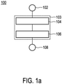
- Fig. 1a shows a flowchart of an embodiment of a method 100 for operating a base station transceiver in controlling transmission of a radio signal to a user equipment according to the invention.
- the base station transceiver and the user equipment are both part of a cellular radio communication system.
- the method starts with a terminator 102 and comprises an algorithm 103 to determine frequency-hopping control information.
- the frequency-hopping control information is indicative of a hopping-frequency set of frequency sub-bands of a downlink frequency band of a downlink channel of the cellular radio communication system, which are to be used for transmission of consecutive radio signal segments of the radio signal to the user equipment.
- the frequency-hopping control information is indicative of a hopping time order of the frequency sub-bands of the hopping-frequency set, which is to be used for the transmission of the consecutive radio signal segments of the radio signal to the user equipment.
- the algorithm 103 comprises two steps 104 and 106.
- step 104 user-equipment hopping-limitation information are ascertained that is indicative of one or more of the frequency sub-bands of the downlink frequency band that are to be excluded from the hopping-frequency set.
- the frequency sub-bands included in the hopping-frequency set are each indicated by a respective center frequency and a respective frequency sub-band width.
- the frequency sub-bands are of smaller width than the other frequency sub-bands, e.g. for sparing impacted frequency regions which could be accordingly used for other devices.
- the hopping frequency set is determined based on the ascertained user-equipment hopping-limitation information.
- a hopping scheme 100' generated with method 100 is shown in Fig. 1b and will be described in the following.
- Fig. 1b shows an exemplary hopping scheme generated with method 100 illustrated in Fig. 1a .
- Fig. 1b the frequency band 122 and 124 of the downlink channel of the base station transceiver and of the user equipment, respectively, are shown as a function of frequency indicated by a coordinate axis labelled "f".
- the hopping frequency set and the hopping time order are illustrated, wherein the a coordinate axis labelled "t" indicates the hopping time order and the coordinate axis "f" the hopping frequency order.
- the downlink frequency band is subdivided into five frequency sub-bands of which only four frequency sub-bands are used as indicated by the rectangles 126, 128, 130, and 132.
- the frequency sub-band for transmission is cyclically changed after a pre-determined period of time. The illustration only shows a single period. In a following period, the transmission is continued with lowest frequency sub-band and the described pattern is repeated.
- the frequency sub-band between the frequency sub-bands corresponding to rectangles 128 and 130 is never used in the hopping scheme.
- the left out frequency sub-band was indicated by the user-equipment hopping-limitation to be excluded for the transmission due to self-interference.
- Self-interference can be caused by functional modules, e.g. DC-DC converter or memory modules, situated in close proximity to a receiver module, which emit signals whose frequencies fall within the frequency band of the downlink channel. The effect of self-interference on the reception sensitivity will be described in the following with reference to Fig. 1c .
- Fig. 1c shows an exemplary illustration 100" how self-interference affects receiver sensitivity of a given user equipment.
- the exemplary illustration 100" shows noise levels of the given user equipment as a function of frequency denoted by a coordinate axis labelled "f", which is indicative of a receiver sensitivity of a receiver module of the given user equipment.
- the unsuppressed noise level of the given user equipment is indicated by an upper noise level 140.
- the receiver sensitivity can be increased by accumulation, which leads to a lower noise level 142.
- the resulting increase in receiver sensitivity is a result of the fact that noise is uncorrelated in time and therefore gets reduced due to destructive interference in the accumulation process.
- Peaks 144.1, 144.2, and 144.3 in the illustration 100" are exemplary illustrations of noise due to self-interference in the frequency range of the downlink frequency band. As noise from self-interference is correlated in time. As a result, those peaks are unaffected by accumulation and remain in a cumulative noise level 146 of peaks 144.1-144.3 and uncorrelated noise after accumulation 142.
- Fig. 2 shows a flowchart of an embodiment of a method 200 for operating a base station transceiver and a user equipment in controlling transmission of a radio signal from the base station transceiver to the user equipment.
- FIG. 1a While the flowchart of Fig. 1a only illustrates the steps of method 100 performed by the base station transceiver, Fig. 2 illustrates steps executed by both the base station transceiver and the user equipment. As a result, the flowchart is sub-divided by a dashed line into a left and a right side.
- the left side also labeled "BST” indicates all those steps of the method that are executed by the base station transceiver while the right side, also labelled "UE”, indicates all steps executed by the user equipment.
- the method 200 starts with terminator 202 followed by an algorithm 204 for determining frequency-hopping control information that is indicative of the hopping-frequency set of frequency sub-bands and the hopping time order of the frequency sub-bands of the hopping frequency set, which is to be used for the transmission of the consecutive radio signal segments of the radio signal from the base station transceiver to the user equipment.
- the algorithm 204 comprises a step 210, in the user equipment sends user-equipment hopping-limitation information in a control exchange to the base station transceiver. In a subsequent step 220, the user-equipment hopping-limitation information is received by the base station transceiver.
- a step 230 the user equipment processes the user-equipment hopping-limitation information for determining the hopping frequency set of the frequency-hopping control information.
- the method 200 stops with terminator 242.
- the user-equipment hopping limitation information is only used to determine the hopping frequency set.
- the base station alternatively or additionally uses the user-equipment hopping-limitation information also for determining the hopping time order.
- the user equipment does not send the user-equipment hopping-limitation information to the base station transceiver, but rather user-equipment type information.
- User-equipment type information can be, for example, parts of the IMEI.
- the user-equipment type information corresponds to a manufacturer and device type information, i.e. the TAC (Type Allocation Code).
- the base station then accesses and searches a look-up table on a server using the obtained user-equipment type information to retrieve the hopping-limitation information assigned to the user-equipment type information.
- the base station transceiver accesses and searches a look-up table on a server using the obtained user-equipment type information to directly retrieve a hopping-frequency set that takes into account the hopping-limitation information assigned to the user-equipment type information.
- the base station transceiver takes into account bandwidth information, labelled "BWI" in Fig. 2 , in step 230.
- the bandwidth information is indicative of a frequency bandwidth occupied by the individual frequency sub-bands, which are to be used for the transmission of the radio signal to the user equipment.
- the bandwidth information is used to determine the hopping frequency set, or determining the hopping time order, or determining the hopping frequency set and the hopping time order.
- Fig. 3 shows a flowchart of a method 300, which is an alternative embodiment of the method 200 of Fig. 2 .
- Steps of the method 300 that are identical to those of the method 200 of Fig. 2 are labeled using the same reference signs. For an explanation of those features, the reader is referred to the description of Fig. 2 . In the following, only those features that are unique to the method 300 will be explained.
- the method 300 comprises an additional step 350, in which the base station transceiver provides to the user equipment minimum-reception-performance information for the frequency sub-bands of the downlink frequency band, wherein the minimum-reception-performance information is indicative of a maximum error rate of reception at the user equipment.
- the user equipment determines the user-equipment hopping-limitation information based on the minimum-reception-performance information and provides the user-equipment hopping-limitation information to the base station transceiver.
- Fig. 4a shows a flowchart of an embodiment of a method for determining further frequency-hopping control information for one or more additional parallel transmissions of radio signals from the base station transceiver to the user equipment. The method is formulated from the point of view of the base station transceiver.
- the method 400 starts with terminator 402 after which a first step 410 is executed.
- step 410 the algorithm 103 of method 700 is executed for determining the frequency-hopping control information.
- the further frequency-hopping control information is determined, wherein the further frequency-hopping control information comprises the hopping frequency set of the determined frequency-hopping control information and a modified hopping time order assigned to the frequency sub-bands of the hopping frequency set.
- the modified hopping time order for each additional parallel transmission is a respective cyclically shifted version of the hopping time order of the determined frequency-hopping control information.
- Fig. 4b shows an exemplary hopping scheme 400' generated using the method of Fig. 4a .
- the hopping scheme 400' shows a parallel transmission of a radio signal to two different devices that support an identical hopping-frequency set.
- the hopping scheme 400' is depicted in the same manner as the hopping scheme 100' of Fig. 1b .
- the frequency band 122 and 124 of the downlink channel of the base station transceiver and of the user equipment, respectively are shown as a function of frequency, wherein a coordinate axis labelled "f" indicates the frequency dependence.
- Fig. 4b the time and frequency dependence of the hopping scheme 400' is shown with the help of the coordinate axis "f" for the frequency dependence and a coordinate axis labeled "t" for the time dependence.
- the downlink frequency band is subdivided into five sub-bands.
- the transmission is performed using two parallel hopping schemes.
- a first hopping scheme is illustrated by the rectangles 126, 128, 130, and 132, which correspond to the hopping scheme 100' shown in Fig. 1b .
- Fig. 4b shows a second hopping scheme illustrated by rectangles 426, 428, 430, and 432.
- the transmission of the first and the second hopping schemes is conducted using the same set of frequency sub-bands.
- the first and the second hopping schemes differ in the time-order in such a way that the first hopping scheme conducts a transmission using that frequency sub-band, which had been used in the previous time step by the second hopping scheme.
- the hopping time order of the second hopping scheme corresponds to a cyclically shifted hopping time order of the first hopping scheme.
- Fig. 4c A more complicated combination of hopping schemes is shown in Fig. 4c .
- the hopping scheme is also generated according to method 400 of Fig. 4a .
- the hopping-frequency set is modified in addition to the hopping time order.
- Fig. 4c shows an alternative exemplary hopping scheme 400" generated using the method of Fig. 4a .
- the hopping scheme 400" is identical to the hopping scheme 400' except for the rectangle 428 of the second hopping scheme, which is replaced by a rectangle 428'.
- the rectangle 428' indicates the usage of the frequency sub-band occupying a middle of the frequency band 122, which was previously unused, as part of the second hopping scheme. As a consequence, the frequency sub-band indicated by rectangle 130 is not used by the second hopping scheme.
- a hopping scheme such as the hopping scheme of Fig. 4c , that are not only based on a different hopping time order, but are also based on a different hopping-frequency set are particularly advantageous when the devices receiving the parallel transmission support different frequency sub-bands due to, e.g. different sources of internal interference.
- the methods previously described include only those steps required for determining the frequency-hopping control information.
- a method will be described that includes additional steps for preparing the transmission of the radio signal.
- Fig. 5 shows shows a flowchart of a method 500, which is an alternative embodiment of the method 200 of Fig. 2 .
- Steps of the method 500 that are identical to those of the method 200 of Fig. 2 are labeled using the same reference signs. For an explanation of those features, the reader is referred to the description of Fig. 2 . In the following, only those features that are unique to the method 500 will be explained.
- the method 500 comprises additional steps 550 and 560.
- the base station transceiver uses the determined frequency-hopping control information to determine scheduling control information for scheduling a transmission of the radio signal from the base station transceiver to the user equipment.
- the scheduling control information are required so that the user equipment knows which frequency sub-bands to listen to for the transmission of the radio signal.
- the base station transceiver provides the determined scheduling control information for transmission to the user equipment in a control communication associated with the transmission of the radio signal to the user equipment.
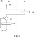
- Fig. 6 shows a flowchart of a method 600, which is yet another alternative embodiment of the method of Fig. 2 .
- Steps of the method 600 that are identical to those of the method 200 of Fig. 2 are labeled using the same reference signs. For an explanation of those features, the reader is referred to the description of Fig. 2 . In the following, only those features that are unique to the method 600 will be explained.
- the base station transceiver verifies in a step 620 whether the user equipment operates in a coverage enhancement mode. To this end, the user equipment provides to the base station transceiver in a step 610 coverage-enhancement-mode information indicative of whether or not the user equipment is being operated in a coverage-enhancement mode defined by a radio communication standard.
- Coverage enhancement mode in this example includes the CEmodeA and the CEmodeB for Cat-M devices and CElevel 1 to CElevel 3 for NB-loT devices.
- the base station transceiver uses a standard hopping algorithm for the transmission of the radio signal to the user equipment (indicated by a branch marked with "N" in Fig. 6 ).
- the user equipment provides information indicative of which coverage enhancement the user equipment is using.
- the algorithm 204 is only executed if the user equipment uses a pre-determined coverage enhancement mode.
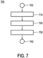
- Fig. 7 shows a flowchart of a method 700 for using frequency-hopping control information in a transmission in response to a Hybrid Automated Repeat Request.
- the method 700 is formulated from the point of view of the base station transceiver. Steps taken by the user equipment are only implicitly referred to.
- the method 700 start with a terminator 702 and is executed in response to receiving one or more repeat requests from a given user equipment.
- the algorithm 103 of method 100 is used for determining the frequency-hopping control information.
- the frequency-hopping control information are used in determining retransmission control information under a Hybrid Automated Repeat Request scheme.
- the base station In a final step 730 of the method 700, the base station providing the determined retransmission control information for transmission to the user equipment in a control communication.
- the method 700 ends with terminator 742.
- Fig. 8 shows a flowchart of a method 800 for performing a handover of a given user equipment from one base station transceiver to a next base station transceiver.
- the method 800 starts with a terminator 802.
- the algorithm 103 of method 100 is executed to determine the frequency-hopping control information.
- the base station transceiver transfers the user-equipment hopping-limitation information to the next base station transceiver in case of a handover.
- This method is particularly advantageous for an intra-frequency handover.
- the algorithm 802 also comprises a step for transferring information about the control enhancement mode used by the user equipment.
- the minimum-reception-performance information signalled to the user equipment by the base station transceiver for determining the user-equipment hopping-limitation information is also transferred to the next base station transceiver.
- a base station transceiver and a user equipment configured to execute one of the methods described above are described with reference to Fig. 9 .
- Fig. 9 illustrates a base station transceiver 920 and a user equipment 910 according to the invention.
- the user equipment in the example of Fig. 9 is a cell phone 910 that communicates with a base station transceiver 920 depicted by a radio signal tower, which are both part of a cellular radio communication system 900.
- the base station transceiver 920 comprises a controller device 920.1 comprising a hopping control unit.
- the hopping control unit is configured to determine frequency-hopping control information that is indicative of a hopping-frequency set of frequency sub-bands of a downlink frequency band of a downlink channel of the cellular radio communication system, which are to be used for transmission of consecutive radio signal segments of a radio signal to the user equipment.
- the frequency-hopping control information is indicative of a hopping time order of the frequency sub-bands of the hopping frequency set, which is to be used for the transmission of the consecutive radio signal segments of the radio signal to the user equipment.
- the hopping control unit is configured to ascertain user-equipment hopping-limitation information that is indicative of one or more of the frequency sub-bands of the downlink frequency band that are to be excluded from the hopping-frequency set due to a perturbation of signal reception at the user equipment caused by self-interference and to determine the hopping frequency set using the user-equipment hopping-limitation information.
- the ascertaining of the user-equipment hopping limitation information is performed by requesting the cell phone 910 to provide the user-equipment hopping limitation information in a control exchange before the transmission of the radio signal.
- the cell phone 910 comprises a controller device 910.1 with a hopping control unit, which is configured to provide to the base station transceiver 920 the user-equipment frequency-limitation information and to subsequently receive the frequency-hopping control information from the base station 920.
Landscapes
- Engineering & Computer Science (AREA)
- Signal Processing (AREA)
- Computer Networks & Wireless Communication (AREA)
- Mobile Radio Communication Systems (AREA)
Priority Applications (8)
| Application Number | Priority Date | Filing Date | Title |
|---|---|---|---|
| EP20192965.0A EP3962190A1 (de) | 2020-08-26 | 2020-08-26 | Verfahren zur steuerung der datenübertragung in einem funkkommunikationssystem |
| PCT/EP2021/073360 WO2022043310A1 (en) | 2020-08-26 | 2021-08-24 | Method for controlling data transmission in a radio communication system |
| KR1020257013300A KR20250065421A (ko) | 2020-08-26 | 2021-08-24 | 라디오 통신 시스템에서 데이터 전송을 제어하기 위한 방법 |
| KR1020237010296A KR20230070222A (ko) | 2020-08-26 | 2021-08-24 | 라디오 통신 시스템에서 데이터 전송을 제어하기 위한 방법 |
| EP21765658.6A EP4205468A1 (de) | 2020-08-26 | 2021-08-24 | Verfahren zur steuerung der datenübertragung in einem funkkommunikationssystem |
| JP2023513920A JP7463639B2 (ja) | 2020-08-26 | 2021-08-24 | 無線通信システムにおけるデータ伝送を制御する方法 |
| CN202180072893.9A CN116803156A (zh) | 2020-08-26 | 2021-08-24 | 用于控制无线电通信系统中的数据传输的方法 |
| US18/042,678 US20230370112A1 (en) | 2020-08-26 | 2021-08-24 | Method for controlling data transmission in a radio communication system |
Applications Claiming Priority (1)
| Application Number | Priority Date | Filing Date | Title |
|---|---|---|---|
| EP20192965.0A EP3962190A1 (de) | 2020-08-26 | 2020-08-26 | Verfahren zur steuerung der datenübertragung in einem funkkommunikationssystem |
Publications (1)
| Publication Number | Publication Date |
|---|---|
| EP3962190A1 true EP3962190A1 (de) | 2022-03-02 |
Family
ID=72266137
Family Applications (2)
| Application Number | Title | Priority Date | Filing Date |
|---|---|---|---|
| EP20192965.0A Withdrawn EP3962190A1 (de) | 2020-08-26 | 2020-08-26 | Verfahren zur steuerung der datenübertragung in einem funkkommunikationssystem |
| EP21765658.6A Pending EP4205468A1 (de) | 2020-08-26 | 2021-08-24 | Verfahren zur steuerung der datenübertragung in einem funkkommunikationssystem |
Family Applications After (1)
| Application Number | Title | Priority Date | Filing Date |
|---|---|---|---|
| EP21765658.6A Pending EP4205468A1 (de) | 2020-08-26 | 2021-08-24 | Verfahren zur steuerung der datenübertragung in einem funkkommunikationssystem |
Country Status (6)
| Country | Link |
|---|---|
| US (1) | US20230370112A1 (de) |
| EP (2) | EP3962190A1 (de) |
| JP (1) | JP7463639B2 (de) |
| KR (2) | KR20250065421A (de) |
| CN (1) | CN116803156A (de) |
| WO (1) | WO2022043310A1 (de) |
Citations (4)
| Publication number | Priority date | Publication date | Assignee | Title |
|---|---|---|---|---|
| US20050232135A1 (en) * | 2004-03-31 | 2005-10-20 | Manabu Mukai | Radio communication system, terminal apparatus and base station apparatus |
| US20080279259A1 (en) * | 2004-07-16 | 2008-11-13 | Takahiro Kobayashi | Radio Communication Apparatus, Base Station and System |
| GB2491908A (en) * | 2011-06-13 | 2012-12-19 | Neul Ltd | Calibration mode in whitespace networks |
| WO2018073812A1 (en) | 2016-10-21 | 2018-04-26 | Telefonaktiebolaget L M Ericsson (Publ) | Coverage extension frequency hopping scheme |
Family Cites Families (3)
| Publication number | Priority date | Publication date | Assignee | Title |
|---|---|---|---|---|
| US6278723B1 (en) * | 2000-03-08 | 2001-08-21 | Motorola, Inc. | Method and apparatus for minimizing a probability of self-interference among neighboring wireless networks |
| JP4382729B2 (ja) | 2005-09-22 | 2009-12-16 | 株式会社東芝 | 無線通信装置および無線通信方法 |
| GB2492052B (en) | 2011-06-13 | 2015-06-24 | Neul Ltd | Interference mitigation |
-
2020
- 2020-08-26 EP EP20192965.0A patent/EP3962190A1/de not_active Withdrawn
-
2021
- 2021-08-24 KR KR1020257013300A patent/KR20250065421A/ko active Pending
- 2021-08-24 KR KR1020237010296A patent/KR20230070222A/ko not_active Ceased
- 2021-08-24 EP EP21765658.6A patent/EP4205468A1/de active Pending
- 2021-08-24 US US18/042,678 patent/US20230370112A1/en active Pending
- 2021-08-24 JP JP2023513920A patent/JP7463639B2/ja active Active
- 2021-08-24 CN CN202180072893.9A patent/CN116803156A/zh active Pending
- 2021-08-24 WO PCT/EP2021/073360 patent/WO2022043310A1/en not_active Ceased
Patent Citations (4)
| Publication number | Priority date | Publication date | Assignee | Title |
|---|---|---|---|---|
| US20050232135A1 (en) * | 2004-03-31 | 2005-10-20 | Manabu Mukai | Radio communication system, terminal apparatus and base station apparatus |
| US20080279259A1 (en) * | 2004-07-16 | 2008-11-13 | Takahiro Kobayashi | Radio Communication Apparatus, Base Station and System |
| GB2491908A (en) * | 2011-06-13 | 2012-12-19 | Neul Ltd | Calibration mode in whitespace networks |
| WO2018073812A1 (en) | 2016-10-21 | 2018-04-26 | Telefonaktiebolaget L M Ericsson (Publ) | Coverage extension frequency hopping scheme |
Also Published As
| Publication number | Publication date |
|---|---|
| KR20250065421A (ko) | 2025-05-12 |
| CN116803156A (zh) | 2023-09-22 |
| WO2022043310A1 (en) | 2022-03-03 |
| KR20230070222A (ko) | 2023-05-22 |
| US20230370112A1 (en) | 2023-11-16 |
| JP2023539655A (ja) | 2023-09-15 |
| JP7463639B2 (ja) | 2024-04-09 |
| EP4205468A1 (de) | 2023-07-05 |
Similar Documents
| Publication | Publication Date | Title |
|---|---|---|
| JP7514916B2 (ja) | データ送信方法と装置 | |
| US11457443B2 (en) | Method for transmitting configuration information and terminal device | |
| JP2023510448A (ja) | 伝送方法、装置、第1の通信ノード、第2の通信ノード、および媒体 | |
| US7865201B2 (en) | HARQ data reception in multiradio device | |
| RU2735383C1 (ru) | Способ передачи данных, оконечное устройство и сетевое устройство | |
| JP7577685B2 (ja) | 通信チャネル状態を予測するためのデバイス、システムおよび方法 | |
| US9743220B2 (en) | Adaptive frequency hopping (AFH) with channel inhibition (CI) for bluetooth | |
| US20060063533A1 (en) | Frequency band allocation device and method | |
| KR20160122668A (ko) | 무선 통신 시스템에서 랜덤 접속 채널을 위한 자원 할당 방법 및 장치 | |
| JP4845644B2 (ja) | 通信方法およびそれを利用した無線装置 | |
| US20230239932A1 (en) | Communication method and apparatus | |
| EP4181595A1 (de) | Kommunikationsverfahren und sidelink-vorrichtung | |
| US20140162715A1 (en) | Channel information providing method, channel information providing database server, and channel information providing system | |
| US10420074B2 (en) | Base station and user equipment | |
| WO2020105191A1 (ja) | 通信装置および無線通信システム | |
| JP5688332B2 (ja) | 無線通信システム | |
| US20230370112A1 (en) | Method for controlling data transmission in a radio communication system | |
| JP2003163652A (ja) | 無線通信装置および無線通信方法 | |
| CN112583528B (zh) | 确定传输块大小的方法和装置 | |
| US9661644B2 (en) | Wireless communication system | |
| KR101768073B1 (ko) | 무선 통신 기술의 채널별 통신 품질 추정 방법 및 장치 | |
| WO2024183005A1 (en) | Power adaptation in unlicensed bands | |
| KR101239796B1 (ko) | 공간 분할 다중 접속 통신 장치 및 방법 | |
| JP4340126B2 (ja) | 基地局装置選択方法およびそれを利用した端末装置 | |
| JP6802747B2 (ja) | 基地局装置、端末装置、制御方法、及びプログラム |
Legal Events
| Date | Code | Title | Description |
|---|---|---|---|
| PUAI | Public reference made under article 153(3) epc to a published international application that has entered the european phase |
Free format text: ORIGINAL CODE: 0009012 |
|
| STAA | Information on the status of an ep patent application or granted ep patent |
Free format text: STATUS: THE APPLICATION HAS BEEN PUBLISHED |
|
| AK | Designated contracting states |
Kind code of ref document: A1 Designated state(s): AL AT BE BG CH CY CZ DE DK EE ES FI FR GB GR HR HU IE IS IT LI LT LU LV MC MK MT NL NO PL PT RO RS SE SI SK SM TR |
|
| STAA | Information on the status of an ep patent application or granted ep patent |
Free format text: STATUS: THE APPLICATION IS DEEMED TO BE WITHDRAWN |
|
| 18D | Application deemed to be withdrawn |
Effective date: 20220903 |