EP3963193B1 - Revêtement acoustique avec fentes à angle oblique - Google Patents
Revêtement acoustique avec fentes à angle oblique Download PDFInfo
- Publication number
- EP3963193B1 EP3963193B1 EP20801595.8A EP20801595A EP3963193B1 EP 3963193 B1 EP3963193 B1 EP 3963193B1 EP 20801595 A EP20801595 A EP 20801595A EP 3963193 B1 EP3963193 B1 EP 3963193B1
- Authority
- EP
- European Patent Office
- Prior art keywords
- slot
- face sheet
- recited
- acoustic liner
- acoustic
- Prior art date
- Legal status (The legal status is an assumption and is not a legal conclusion. Google has not performed a legal analysis and makes no representation as to the accuracy of the status listed.)
- Active
Links
Images



Classifications
-
- F—MECHANICAL ENGINEERING; LIGHTING; HEATING; WEAPONS; BLASTING
- F02—COMBUSTION ENGINES; HOT-GAS OR COMBUSTION-PRODUCT ENGINE PLANTS
- F02C—GAS-TURBINE PLANTS; AIR INTAKES FOR JET-PROPULSION PLANTS; CONTROLLING FUEL SUPPLY IN AIR-BREATHING JET-PROPULSION PLANTS
- F02C7/00—Features, components parts, details or accessories, not provided for in, or of interest apart form groups F02C1/00 - F02C6/00; Air intakes for jet-propulsion plants
- F02C7/04—Air intakes for gas-turbine plants or jet-propulsion plants
- F02C7/045—Air intakes for gas-turbine plants or jet-propulsion plants having provisions for noise suppression
-
- F—MECHANICAL ENGINEERING; LIGHTING; HEATING; WEAPONS; BLASTING
- F02—COMBUSTION ENGINES; HOT-GAS OR COMBUSTION-PRODUCT ENGINE PLANTS
- F02C—GAS-TURBINE PLANTS; AIR INTAKES FOR JET-PROPULSION PLANTS; CONTROLLING FUEL SUPPLY IN AIR-BREATHING JET-PROPULSION PLANTS
- F02C7/00—Features, components parts, details or accessories, not provided for in, or of interest apart form groups F02C1/00 - F02C6/00; Air intakes for jet-propulsion plants
- F02C7/24—Heat or noise insulation
-
- F—MECHANICAL ENGINEERING; LIGHTING; HEATING; WEAPONS; BLASTING
- F02—COMBUSTION ENGINES; HOT-GAS OR COMBUSTION-PRODUCT ENGINE PLANTS
- F02K—JET-PROPULSION PLANTS
- F02K1/00—Plants characterised by the form or arrangement of the jet pipe or nozzle; Jet pipes or nozzles peculiar thereto
- F02K1/78—Other construction of jet pipes
- F02K1/82—Jet pipe walls, e.g. liners
- F02K1/827—Sound absorbing structures or liners
-
- F—MECHANICAL ENGINEERING; LIGHTING; HEATING; WEAPONS; BLASTING
- F05—INDEXING SCHEMES RELATING TO ENGINES OR PUMPS IN VARIOUS SUBCLASSES OF CLASSES F01-F04
- F05D—INDEXING SCHEME FOR ASPECTS RELATING TO NON-POSITIVE-DISPLACEMENT MACHINES OR ENGINES, GAS-TURBINES OR JET-PROPULSION PLANTS
- F05D2250/00—Geometry
- F05D2250/20—Three-dimensional
- F05D2250/28—Three-dimensional patterned
- F05D2250/283—Three-dimensional patterned honeycomb
-
- F—MECHANICAL ENGINEERING; LIGHTING; HEATING; WEAPONS; BLASTING
- F05—INDEXING SCHEMES RELATING TO ENGINES OR PUMPS IN VARIOUS SUBCLASSES OF CLASSES F01-F04
- F05D—INDEXING SCHEME FOR ASPECTS RELATING TO NON-POSITIVE-DISPLACEMENT MACHINES OR ENGINES, GAS-TURBINES OR JET-PROPULSION PLANTS
- F05D2260/00—Function
- F05D2260/96—Preventing, counteracting or reducing vibration or noise
-
- F—MECHANICAL ENGINEERING; LIGHTING; HEATING; WEAPONS; BLASTING
- F05—INDEXING SCHEMES RELATING TO ENGINES OR PUMPS IN VARIOUS SUBCLASSES OF CLASSES F01-F04
- F05D—INDEXING SCHEME FOR ASPECTS RELATING TO NON-POSITIVE-DISPLACEMENT MACHINES OR ENGINES, GAS-TURBINES OR JET-PROPULSION PLANTS
- F05D2260/00—Function
- F05D2260/96—Preventing, counteracting or reducing vibration or noise
- F05D2260/964—Preventing, counteracting or reducing vibration or noise counteracting thermoacoustic noise
-
- Y—GENERAL TAGGING OF NEW TECHNOLOGICAL DEVELOPMENTS; GENERAL TAGGING OF CROSS-SECTIONAL TECHNOLOGIES SPANNING OVER SEVERAL SECTIONS OF THE IPC; TECHNICAL SUBJECTS COVERED BY FORMER USPC CROSS-REFERENCE ART COLLECTIONS [XRACs] AND DIGESTS
- Y02—TECHNOLOGIES OR APPLICATIONS FOR MITIGATION OR ADAPTATION AGAINST CLIMATE CHANGE
- Y02T—CLIMATE CHANGE MITIGATION TECHNOLOGIES RELATED TO TRANSPORTATION
- Y02T50/00—Aeronautics or air transport
- Y02T50/60—Efficient propulsion technologies, e.g. for aircraft
Definitions
- a typical acoustic liner includes a cellular structure sandwiched between a back sheet and a perforated face sheet. The liner may be used in the fan case or nacelle of the engine.
- US2002/036115 discloses a noise attenuation panel used to attenuate noise in aircraft engines includes a cellular core and a facing sheet formed with an array of holes.
- the invention provides an acoustic liner for a gas turbine engine as claimed in claim 1.
- each elongated slot defines a slot length (L) and a slot width (W), and a ratio of L to W is from 2 to 10.
- the elongated slots are arranged in multiple circumferential rows.
- each elongated slot defines a slot width (W)
- the elongated slots define a slot-to-slot spacing (S)
- a ratio of S to W is from 2 to 10.
- the elongated slots are linear.
- the elongated slots are parallel to each other.
- the oblique angles are from 37° to 65°.
- each elongated slot defines a slot width (W)
- face sheet defines a thickness (T)
- width (W) is from 0.005 to 0.07 inches (about 0.13mm to 1.78mm)
- thickness (T) is from 0.02 to 0.1 inches (about 0.51mm to 2.54mm).
- elongated slots are arranged in adjacent slot patterns, each elongated slot defines a slot width (W), each one of the adjacent slot patterns defines a minimum pattern-to-pattern gap (G), and a ratio of the pattern-to-pattern gap (G) to the slot width (W) is 2 or greater.
- the elongated slots are aligned with cells of the cellular structure.
- the present invention provides a method of fabricating a face sheet for an acoustic liner as claimed in claim 12.
- the face sheet is formed on a cellular structure and the slot centerlines are sloped at oblique angles to the central axis.
- the elongated slots are formed in alignment with cells of the cellular structure.
- the face sheet is fused directly to the cellular structure without an adhesive.
- FIG. 1 schematically illustrates a gas turbine engine 20.
- the engine 20 generally includes a fan 22, a compressor section 24, a combustor 26, and a turbine section 28.
- the turbine section 28 is coupled by a shaft 30 to the compressor section 24 and the fan 22, which are all rotatable about a central engine axis A.
- the shaft 30 may be coupled through a speed reduction gear 31 to the fan 22.
- a housing 32 such as a casing and/or nacelle, surrounds the fan 22.
- a core case 34 surrounds the core engine components, such as the compressor section 24 and the turbine section 28.
- the portion of the housing 32 aft of the fan 22 and the core case 34 define a bypass passage B there between.
- the portion of the housing 32 forward of the fan 22 defines an inlet region 36.
- the housing 32 includes one or more acoustic liners 38 for reducing noise.
- the housing 32 includes acoustic liners 38 forward of the fan 22 in the inlet region 36 and forward fan case, another acoustic liner 38 at an inter-stage location between the fan 22 and exit guide vanes 40, a trailing acoustic liner 38 aft of the exit guide vanes 40, and an acoustic liner 38 in the tailpipe.
- the liners 38 in the housing 32 are located on the outer boundary of the inlet region 36 and bypass passage B.
- the core case 34 can include an acoustic liner 38 on the inner boundary of the bypass passage B and/or in the tailpipe. As will be appreciated, such locations are for example only, and acoustic liners 38 may be excluded from one or more of the locations shown and/or additionally used elsewhere in the engine 20.
- the acoustic liner 38 is generally provided as an annular structure.
- the acoustic liner 38 can be constructed of one or more acoustic panels 42, a representative one of which is shown in cross-section in Figure 2 .
- the one or more panels 42 are curved about a central axis which is coincident with the central engine axis A.
- the panel 42 may be attached to a structural portion of the housing 32 or core case 34 in a known manner, such as with fasteners.
- panels 42 may be provided as arc segments that are attached to provide the annular structure.
- the panel 42 includes a support backing 44 (e.g., a back sheet), a face sheet 46, and a cellular structure 48 (e.g., a honeycomb structure) disposed between the support backing 44 and the face sheet 46.
- the face sheet 46 faces toward, and is exposed to, the acoustic environment, which in the illustrated engine 20 is the bypass passage B or inlet region 36.
- the support backing 44, the face sheet 46, and the cellular structure 48 can be composed of metal alloys, polymers, or composites, and may be attached together, such as with an adhesive, soldering, or brazing, as applicable.
- the architecture of the panel 42, having a single layer of the cellular structure 48 is what is known as a "single degree of freedom" construction.
- this disclosure is not limited to such architectures and the examples herein can also be applied to "double degree of freedom" constructions, "three degree of freedom” constructions, as well as other architectures.
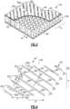
- the slots 50 are provided in a pattern as represented at 55 that is defined by the number of slot rows 52, the slot width (W), the slot angle (OA) relative to the engine axis A, the ratio of the slot length (L) to slot width (W), the ratio of the slot spacing (S) to slot width (W), and the ratio of slot offset (Q) to slot length (L).
- the slot length (L) is the end-to-end length between the ends 50a/50b taken along the slot centerlines C, while the slot width (W) is the distance between the sides 50c/50d taken perpendicular to the slot centerline C.
- the slot-to-slot spacing (S) is the distance between the side 50c of one slot 50 and the side 50d of the next adjacent slot 50 taken perpendicular to the slot centerlines C.
- the slot offset (Q) is the circumferential spacing between ends 50a of adjacent slots 50, measured in the direction of fan rotation, which is denoted by R in Figure 4 .
- Figures 5A , 5B , and 5C show, respectively, three exemplary slot patterns. In Figure 5A the slot pattern has a positive offset, in Figure 5B the slot pattern has a zero offset, and in Figure 5C the slot pattern has a negative offset.
- the positive or negative offsets are taken with regard to the direction of fan rotation R, in which offset in the direction of fan rotation R is positive and offset in the direction opposite the fan direction is negative.
- the face sheet 46 may have one or more slot patterns, for example 55, 56, 57 and 58, which are circumferentially spaced by the pitch (P).
- the pitch (P) establishes the smallest or minimum pattern-to-pattern gap (G) between the two closest points, 50e and 50f, on adjacent patterns, for example slot patterns 55 and 56.
- the slot patterns 55, 56, 57 and 58 are identical to each other and uniformly spaced.
- the face sheet is not limited to such a configuration and may contain different slot patterns and pitches.
- the slotted face sheet 46 has thickness (T), which is the distance between surface 46a and surface 46b taken perpendicular to surface 46a.
- the thickness (T) may be variable in a direction D1, which may be parallel to the engine axis A.
- the slotted face sheet 46 may have its thickest value near the fan 22 trailing edge TE to improve its capability to withstand impact from ice that may be shed from the fan 22.
- the slots 50, or at least groups of the slots 50 are parallel to each other. Additionally, the slots 50, or at least groups of the slots 50, are all of the same length and width. As also shown in Figure 4 , the slots 50, or groups of slots 50, can be arranged in a circumferential row 52 (the central engine axis A is shown for reference). In the illustrated example, the slots 50 are arranged in six circumferential rows, but additional or fewer circumferential rows may be used.
- Perforations in acoustic liners can create drag that debits aerodynamic performance of an engine.
- the slots 50 of the panel 42 are sloped with regard the angular orientations of the slots 50 to the central engine axis A to reduce drag.
- each slot 50 is sloped at an oblique angle (OA) to the central axis about which the panel 42 is curved (i.e., the central engine axis A).
- the angles are defined by the slot centerlines C and the central engine axis A.
- the angles (OA) are from 37° to 65°.
- the axially aft slot end 50a of each slot 50 is circumferentially offset from the axially forward slot end 50b of the slot 50.
- the slots 50 are oriented at the angles (OA) such that the slots 50 are approximately perpendicular to an expected airflow direction, represented at AD in Figure 4 .
- the panel 42 may especially be employed in locations aft of the fan 22 where there is directional oblique airflow from the fan and, in particular, at an inter-stage location between the fan 22 and the exit guide vanes 40.
- the airflow in this inter-stage location, prior to being straightened by the exit guide vanes, is non-axial.
- the slots 50 are angled such that the non-axial airflow moves across the slots 50 rather than travelling substantially along the length of the slots 50.
- the airflow direction may be the airflow from the fan 22 at an acoustic certification condition, such as the approach, lateral or flyover condition, and may be determined from computer simulation and/or engine testing.
- the airflow direction is from about 30° to 48° with respect to the angle formed with the engine central axis A.
- the orientation of the slots 50 to reduce drag may also be represented with regard to a slot texture 54 (e.g., see Figure 4 ).
- the slots 50 collectively define the slot texture 54, schematically shown with single-headed arrows aligned with the slot centerlines C.
- the slot texture 54 is determined by the angles (OA) of the slots 50 and the relative axial and circumferential positions of the ends 50a/50b.
- the axially forward slot end 50b is situated axially upstream, or forward, of the axially aft slot end 50a with respect to the airflow through the engine 20 from the front of the engine (at the inlet region 36) to the back of the engine 20.
- the ends 50a/50b are also circumferentially offset.
- Such a configuration establishes a sloped directionality along the slot centerlines C from the axially forward slot end 50b to the axially aft slot end 50a.
- the single-headed arrows represent this directionality and thus the slot texture 54.
- the slot texture 54 is not limited to texture of rectangular elongated slots 50, and slots having other geometries with upstream and downstream ends may likewise define a slot texture.
- the fan 22 rotates in a rotational direction, which is represented at R in Figure 4 .
- the rotational direction R establishes a circumferentially forward direction in the direction of the rotation and a circumferentially aft direction opposite to the direction of the rotation.
- the rotational direction R of the fan 22 is against the slot texture 54. That is, the axially forward slot ends 50b are circumferentially forward of the axially aft slot ends relative to the rotational direction R of the fan 22.
- the blade passes by the circumferential position of the axial aft slot end 50a of the slot 50 before then passing by the circumferential position of the axially forward slot end 50b of that slot 50.
- the face sheet 46 and slots 50 may be designed to enhance acoustic attenuation and drag reduction, and must be able to withstand impact from ice that may shed from the fan.
- the face sheet thickness (T) is from 0.02 to 0.1 inches (about 0.51mm to 2.54mm)
- the slot width (W) is from 0.005 to 0.07 inches (about 0.13mm to 1.78mm)
- the ratio of the slot length (L) to the slot width (W) is from 2 to 10
- the ratio of the slot-to-slot spacing (S) to the slot width (W) is from 2 to 10
- the ratio of pattern-to-pattern gap (G) to slot width (W) is 2 or greater (where each parameter is measured in inches or equivalent units and each of the ratios specified is non-dimensional).
- the face sheet 46 and slots 50 can be fabricated by subtractive machining, such as by using shaped tools and secondary processes to cut the slots 50 and smooth the edges of the slots 50.
- additive manufacturing can be used to fabricate the face sheet 46 and slots 50.
- additive manufacturing may enable smoother surfaces and edges that are free or substantially free of burrs to further reduce drag, as well as more complex geometries.
- additive manufacturing may enable the pattern of the slots 50 to be produced in alignment with the cells of the cellular structure 48 and avoid or reduce configurations in which the slots 50 overlap the walls of the cellular structure 48 so that the walls do not block the slots 50.
- Additive manufacturing also enables a wider variety of possible materials for the face sheet 46, as additive manufacturing can be conducted for metals or polymers.
- additive manufacturing techniques allow for the creation of a component, such as the face sheet 46, by building the component with successively added layers; e.g., layers of powdered material.
- layers e.g., layers of powdered material.
- one or more materials are deposited on a surface in a layer.
- the layers are subsequently compacted.
- the powder material(s) of the layer may be subsequently fused using any one of a number of known processes (e.g., laser, electron beam, etc.).
- the deposition of the material i.e. the geometry of the deposition later for each of the materials
- CAD computer aided design
- the three-dimensional (3D) model is converted into a plurality of slices, with each slice defining a cross section of the component for a predetermined height (i.e. layer) of the 3D model.
- the additively manufactured component is then "built" layer by layer; e.g., a layer of powdered material(s) is deposited and then fused, and then the process is repeated for the next layer.
- additive manufacturing processes include, but are not limited to, Stereolithography (SLS), Direct Selective Laser Sintering (DSLS), Electron Beam Sintering (EBS), Electron Beam Melting (EBM), Laser Engineered Net Shaping (LENS), Laser Net Shape Manufacturing (LNSM), Direct Metal Deposition (DMD), Direct Metal Laser Sintering (DMLS), "material extrusion” or fused filament fabrication (FFF), "vat polymerization” such as stereolithography (SLA) and digital light projection (DLP), polyjet, and selective laser sintering (SLS), and others.
- SLS Stereolithography
- DSLS Direct Selective Laser Sintering
- EBS Electron Beam Sintering
- EBM Electron Beam Melting
- LENS Laser Engineered Net Shaping
- LNSM Laser Net Shape Manufacturing
- DMD Direct Metal Deposition
- DMLS Direct Metal Laser Sintering
- FFF fused filament fabrication
- VFF vat polymerization
- SLA stereolithography
- DLP digital light projection
Landscapes
- Engineering & Computer Science (AREA)
- Chemical & Material Sciences (AREA)
- Combustion & Propulsion (AREA)
- Mechanical Engineering (AREA)
- General Engineering & Computer Science (AREA)
- Structures Of Non-Positive Displacement Pumps (AREA)
Claims (15)
- Revêtement acoustique (38) pour un moteur à turbine à gaz (20), comprenant :un panneau acoustique (42) qui est courbé autour d'un axe central, le panneau acoustique (42) comprenant,un renforcement de support (44),une feuille de face (46), etune structure cellulaire (48) disposée entre le renforcement de support (44) et la feuille de face (46),la feuille de face (46) comportant des fentes allongées (50) se prolongeant le long des axes centraux des fentes (C) respectifs dans le plan de la feuille de face (46), les axes centraux des fentes (C) étant inclinés à des angles obliques par rapport à l'axe central,caractérisé en ce que la feuille de face (46) varie en dureté.
- Revêtement acoustique (38) selon la revendication 1, dans lequel chaque fente allongée (50) définit une longueur de fente (L) et une largeur de fente (W), et un rapport de L à W est de 2 à 10.
- Revêtement acoustique (38) selon la revendication 1 ou 2, dans lequel les fentes allongées (50) sont disposées en plusieurs rangées circonférentielles.
- Revêtement acoustique (38) selon la revendication 1, 2 ou 3, dans lequel chaque fente allongée (50) définit une largeur de fente (W), les fentes allongées (50) définissent un espacement fente à fente (S), et un rapport de S à W est de 2 à 10.
- Revêtement acoustique (38) selon l'une quelconque des revendications précédentes, dans lequel les fentes allongées (50) sont linéaires.
- Revêtement acoustique (38) selon l'une quelconque des revendications précédentes, dans lequel les fentes allongées (50) sont parallèles les unes aux autres.
- Revêtement acoustique (38) selon l'une quelconque des revendications précédentes, dans lequel les angles obliques sont compris entre 37° et 65°.
- Revêtement acoustique (38) selon l'une quelconque des revendications précédentes, dans lequel chaque fente allongée (50) définit une largeur de fente (W), ladite feuille de face (46) définit une épaisseur (T), ladite largeur (W) est de 0,005 à 0,07 pouce (environ 0,13 mm à 1,78 mm), et ladite épaisseur (T) est de 0,02 à 0,1 pouce (environ 0,51 mm à 2,54 mm) .
- Revêtement acoustique (38) selon l'une quelconque des revendications précédentes, dans lequel lesdites fentes allongées (50) sont disposées selon des motifs de fentes adjacents, chaque dite fente allongée (50) définit une largeur de fente (W), chacun desdits motifs de fentes adjacents définit un espace motif à motif minimal (G), et un rapport dudit espace motif à motif (G) à ladite largeur de fente (W) est de 2 ou plus.
- Revêtement acoustique (38) tel que décrit dans l'une quelconque des revendications précédentes, dans lequel les fentes allongées (50) sont alignées avec les cellules de la structure cellulaire (48).
- Moteur à turbine à gaz (20), comprenant :un ventilateur (22) rotatif autour d'un axe central du moteur (A) ;un carter de ventilateur (32) entourant le ventilateur, le carter de ventilateur (32) comprenant une doublure acoustique (38) telle que décrite dans l'une quelconque des revendications 1 à 9,le revêtement acoustique (38) comportant un ou plusieurs panneaux acoustiques (42),dans lequel l'axe central est l'axe central du moteur (A).
- Procédé de fabrication d'une feuille de face pour un revêtement acoustique (38) tel que défini dans l'une quelconque des revendications précédentes, le procédé comprenant :former une feuille de face (46) par fabrication additive, dans laquelle la feuille de face (46) est courbée autour d'un axe central et qui présente des fentes allongées (50) se prolongeant le long des axes centraux des fentes respectifs (C) dans le plan de la feuille de face (46),caractérisé en ce que la fabrication additive utilise des polymères de duretés différentes de telle sorte que la feuille de face (38) varie en dureté.
- Procédé tel que récité dans la revendication 12, dans lequel la feuille de face (46) est formée sur une structure cellulaire (48) et les axes centraux des fentes (C) sont inclinés à des angles obliques par rapport à l'axe central.
- Procédé tel que récité dans la revendication 13, dans lequel les fentes allongées (50) sont formées en alignement avec les cellules de la structure cellulaire (48).
- Procédé tel que récité dans la revendication 13 ou 14, dans lequel la feuille de face (46) est fusionnée directement à la structure cellulaire (48) sans adhésif.
Applications Claiming Priority (3)
| Application Number | Priority Date | Filing Date | Title |
|---|---|---|---|
| US201962843111P | 2019-05-03 | 2019-05-03 | |
| US16/411,728 US11480106B2 (en) | 2019-05-03 | 2019-05-14 | Acoustic liner with obliquely angled slots |
| PCT/US2020/031364 WO2020227237A1 (fr) | 2019-05-03 | 2020-05-04 | Revêtement acoustique avec fentes à angle oblique |
Publications (3)
| Publication Number | Publication Date |
|---|---|
| EP3963193A1 EP3963193A1 (fr) | 2022-03-09 |
| EP3963193A4 EP3963193A4 (fr) | 2023-06-14 |
| EP3963193B1 true EP3963193B1 (fr) | 2025-01-15 |
Family
ID=73017380
Family Applications (1)
| Application Number | Title | Priority Date | Filing Date |
|---|---|---|---|
| EP20801595.8A Active EP3963193B1 (fr) | 2019-05-03 | 2020-05-04 | Revêtement acoustique avec fentes à angle oblique |
Country Status (3)
| Country | Link |
|---|---|
| US (1) | US11480106B2 (fr) |
| EP (1) | EP3963193B1 (fr) |
| WO (1) | WO2020227237A1 (fr) |
Families Citing this family (12)
| Publication number | Priority date | Publication date | Assignee | Title |
|---|---|---|---|---|
| US12109793B2 (en) * | 2019-11-21 | 2024-10-08 | Rtx Corporation | Composite skins having variable hole sizes and shapes formed using photomachining |
| US12110844B2 (en) * | 2022-11-15 | 2024-10-08 | Rohr, Inc. | Zoned liner exhaust with buried N-core |
| US20240343413A1 (en) * | 2023-04-17 | 2024-10-17 | The Boeing Company | Cellular Core for Aircraft Acoustic Panel and Method of Manufacture |
| US12546258B2 (en) | 2023-05-31 | 2026-02-10 | Rtx Corporation | Acoustic treatment made by additive manufacturing |
| US12359584B1 (en) * | 2024-01-03 | 2025-07-15 | Honeywell International Inc. | Acoustic engine casing for gas turbine engine |
| US12428962B1 (en) | 2024-06-14 | 2025-09-30 | General Electric Company | Gas turbine engine with acoustic spacing of the fan blades and outlet guide vanes |
| US12429067B1 (en) | 2024-06-14 | 2025-09-30 | General Electric Company | Gas turbine engine with acoustic spacing of the fan blades and outlet guide vanes |
| US12292017B1 (en) * | 2024-06-14 | 2025-05-06 | General Electric Company | Gas turbine engine with acoustic spacing of the fan blades and outlet guide vanes |
| US12497923B1 (en) | 2024-06-14 | 2025-12-16 | General Electric Company | Gas turbine engine with acoustic spacing of the fan blades and outlet guide vanes |
| US12421854B1 (en) * | 2024-06-14 | 2025-09-23 | General Electric Company | Gas turbine engine with acoustic spacing of the fan blades and outlet guide vanes |
| US12560125B2 (en) | 2024-06-14 | 2026-02-24 | General Electric Company | Gas turbine engine with acoustic spacing of the fan blades and outlet guide vanes |
| US12510104B2 (en) | 2024-06-14 | 2025-12-30 | General Electric Company | Gas turbine engine with acoustic spacing of the fan blades and outlet guide vanes |
Family Cites Families (12)
| Publication number | Priority date | Publication date | Assignee | Title |
|---|---|---|---|---|
| GB0016149D0 (en) * | 2000-06-30 | 2000-08-23 | Short Brothers Plc | A noise attenuation panel |
| US8602156B2 (en) * | 2006-05-19 | 2013-12-10 | United Technologies Corporation | Multi-splice acoustic liner |
| US7540354B2 (en) | 2006-05-26 | 2009-06-02 | United Technologies Corporation | Micro-perforated acoustic liner |
| US20100206664A1 (en) * | 2007-07-12 | 2010-08-19 | Rolls-Royce Plc | Acoustic panel |
| US10184398B2 (en) | 2013-10-17 | 2019-01-22 | Rohr, Inc. | Acoustic structural panel with slanted core |
| US9604438B2 (en) | 2014-04-30 | 2017-03-28 | The Boeing Company | Methods and apparatus for noise attenuation in an engine nacelle |
| US20160215700A1 (en) * | 2015-01-23 | 2016-07-28 | Rohr, Inc. | Inner fixed structure acoustic panel with directional perforations |
| US10961913B2 (en) | 2015-03-10 | 2021-03-30 | Mra Systems, Llc | Acoustic liners for use in a turbine engine |
| FR3041704B1 (fr) * | 2015-09-29 | 2017-11-03 | Snecma | Panneau d'echange thermique et de reduction de bruit pour un ensemble propulsif |
| US10443496B2 (en) | 2016-07-18 | 2019-10-15 | The Boeing Company | Acoustic paneling |
| US20180029719A1 (en) * | 2016-07-28 | 2018-02-01 | The Boeing Company | Drag reducing liner assembly and methods of assembling the same |
| US10332501B2 (en) * | 2017-02-01 | 2019-06-25 | General Electric Company | Continuous degree of freedom acoustic cores |
-
2019
- 2019-05-14 US US16/411,728 patent/US11480106B2/en active Active
-
2020
- 2020-05-04 EP EP20801595.8A patent/EP3963193B1/fr active Active
- 2020-05-04 WO PCT/US2020/031364 patent/WO2020227237A1/fr not_active Ceased
Also Published As
| Publication number | Publication date |
|---|---|
| WO2020227237A1 (fr) | 2020-11-12 |
| EP3963193A4 (fr) | 2023-06-14 |
| US11480106B2 (en) | 2022-10-25 |
| EP3963193A1 (fr) | 2022-03-09 |
| US20200347785A1 (en) | 2020-11-05 |
Similar Documents
| Publication | Publication Date | Title |
|---|---|---|
| US11480106B2 (en) | Acoustic liner with obliquely angled slots | |
| CN110494632B (zh) | 具有冷却流体通道的增材制造的机械紧固件 | |
| US11098601B2 (en) | Diffuser-deswirler for a gas turbine engine | |
| CN112585335B (zh) | 用于涡轮发动机的增材制造的嵌套段组件 | |
| US11131247B2 (en) | Additively manufactured rotating shaft | |
| CN111441829B (zh) | 具有冷却孔的涡轮发动机的部件 | |
| US12286902B2 (en) | Turbomachine cooling trench | |
| CN110735665B (zh) | 具有可调节冷却构造的翼型件 | |
| CN107084157B (zh) | 容纳壳体沟槽填充层和容纳来自可旋转机器的脱扣部件的方法 | |
| US10458251B2 (en) | Airfoil cooling using non-line of sight holes | |
| EP2947273B1 (fr) | Pale et procédé de refroidissement associé d'une pale | |
| CN115726844B (zh) | 具有格子结构的耐磨插入件 | |
| CN112240227A (zh) | 涡轮发动机翼型件 | |
| US20160290139A1 (en) | Gas turbine engine component cooling passage turbulator | |
| US20250035038A1 (en) | Gas turbine engine having a heat exchanger located in an annular duct | |
| US20230286640A1 (en) | Acoustic absorber for a gas turbine engine | |
| US20210256947A1 (en) | Acoustic cores and methods for splicing acoustic cores | |
| EP3287598B1 (fr) | Éléments de refroidissement à géométrie de chevrons en trois dimensions | |
| CN115199354B (zh) | 复合角度加速器 | |
| EP3399148B1 (fr) | Aube refroidie pour un moteur à turbine à gaz | |
| US12312969B2 (en) | Airfoils for turbofan engines | |
| US10724376B2 (en) | Airfoil having integral fins | |
| CN116733786A (zh) | 用于燃气涡轮发动机的吸声器 |
Legal Events
| Date | Code | Title | Description |
|---|---|---|---|
| STAA | Information on the status of an ep patent application or granted ep patent |
Free format text: STATUS: THE INTERNATIONAL PUBLICATION HAS BEEN MADE |
|
| PUAI | Public reference made under article 153(3) epc to a published international application that has entered the european phase |
Free format text: ORIGINAL CODE: 0009012 |
|
| STAA | Information on the status of an ep patent application or granted ep patent |
Free format text: STATUS: REQUEST FOR EXAMINATION WAS MADE |
|
| 17P | Request for examination filed |
Effective date: 20211130 |
|
| AK | Designated contracting states |
Kind code of ref document: A1 Designated state(s): AL AT BE BG CH CY CZ DE DK EE ES FI FR GB GR HR HU IE IS IT LI LT LU LV MC MK MT NL NO PL PT RO RS SE SI SK SM TR |
|
| DAV | Request for validation of the european patent (deleted) | ||
| DAX | Request for extension of the european patent (deleted) | ||
| A4 | Supplementary search report drawn up and despatched |
Effective date: 20230517 |
|
| RIC1 | Information provided on ipc code assigned before grant |
Ipc: F02K 1/82 20060101ALI20230511BHEP Ipc: F02C 7/045 20060101AFI20230511BHEP |
|
| RAP3 | Party data changed (applicant data changed or rights of an application transferred) |
Owner name: RTX CORPORATION |
|
| GRAP | Despatch of communication of intention to grant a patent |
Free format text: ORIGINAL CODE: EPIDOSNIGR1 |
|
| STAA | Information on the status of an ep patent application or granted ep patent |
Free format text: STATUS: GRANT OF PATENT IS INTENDED |
|
| INTG | Intention to grant announced |
Effective date: 20240828 |
|
| GRAS | Grant fee paid |
Free format text: ORIGINAL CODE: EPIDOSNIGR3 |
|
| GRAA | (expected) grant |
Free format text: ORIGINAL CODE: 0009210 |
|
| STAA | Information on the status of an ep patent application or granted ep patent |
Free format text: STATUS: THE PATENT HAS BEEN GRANTED |
|
| AK | Designated contracting states |
Kind code of ref document: B1 Designated state(s): AL AT BE BG CH CY CZ DE DK EE ES FI FR GB GR HR HU IE IS IT LI LT LU LV MC MK MT NL NO PL PT RO RS SE SI SK SM TR |
|
| REG | Reference to a national code |
Ref country code: CH Ref legal event code: EP Ref country code: GB Ref legal event code: FG4D |
|
| REG | Reference to a national code |
Ref country code: DE Ref legal event code: R096 Ref document number: 602020044895 Country of ref document: DE |
|
| REG | Reference to a national code |
Ref country code: IE Ref legal event code: FG4D |
|
| REG | Reference to a national code |
Ref country code: NL Ref legal event code: MP Effective date: 20250115 |
|
| PG25 | Lapsed in a contracting state [announced via postgrant information from national office to epo] |
Ref country code: NL Free format text: LAPSE BECAUSE OF FAILURE TO SUBMIT A TRANSLATION OF THE DESCRIPTION OR TO PAY THE FEE WITHIN THE PRESCRIBED TIME-LIMIT Effective date: 20250115 |
|
| PG25 | Lapsed in a contracting state [announced via postgrant information from national office to epo] |
Ref country code: RS Free format text: LAPSE BECAUSE OF FAILURE TO SUBMIT A TRANSLATION OF THE DESCRIPTION OR TO PAY THE FEE WITHIN THE PRESCRIBED TIME-LIMIT Effective date: 20250415 |
|
| PG25 | Lapsed in a contracting state [announced via postgrant information from national office to epo] |
Ref country code: FI Free format text: LAPSE BECAUSE OF FAILURE TO SUBMIT A TRANSLATION OF THE DESCRIPTION OR TO PAY THE FEE WITHIN THE PRESCRIBED TIME-LIMIT Effective date: 20250115 |
|
| PG25 | Lapsed in a contracting state [announced via postgrant information from national office to epo] |
Ref country code: PL Free format text: LAPSE BECAUSE OF FAILURE TO SUBMIT A TRANSLATION OF THE DESCRIPTION OR TO PAY THE FEE WITHIN THE PRESCRIBED TIME-LIMIT Effective date: 20250115 |
|
| PGFP | Annual fee paid to national office [announced via postgrant information from national office to epo] |
Ref country code: DE Payment date: 20250423 Year of fee payment: 6 |
|
| PG25 | Lapsed in a contracting state [announced via postgrant information from national office to epo] |
Ref country code: ES Free format text: LAPSE BECAUSE OF FAILURE TO SUBMIT A TRANSLATION OF THE DESCRIPTION OR TO PAY THE FEE WITHIN THE PRESCRIBED TIME-LIMIT Effective date: 20250115 |
|
| PGFP | Annual fee paid to national office [announced via postgrant information from national office to epo] |
Ref country code: GB Payment date: 20250423 Year of fee payment: 6 |
|
| REG | Reference to a national code |
Ref country code: LT Ref legal event code: MG9D |
|
| PG25 | Lapsed in a contracting state [announced via postgrant information from national office to epo] |
Ref country code: IS Free format text: LAPSE BECAUSE OF FAILURE TO SUBMIT A TRANSLATION OF THE DESCRIPTION OR TO PAY THE FEE WITHIN THE PRESCRIBED TIME-LIMIT Effective date: 20250515 Ref country code: NO Free format text: LAPSE BECAUSE OF FAILURE TO SUBMIT A TRANSLATION OF THE DESCRIPTION OR TO PAY THE FEE WITHIN THE PRESCRIBED TIME-LIMIT Effective date: 20250415 |
|
| REG | Reference to a national code |
Ref country code: AT Ref legal event code: MK05 Ref document number: 1759979 Country of ref document: AT Kind code of ref document: T Effective date: 20250115 |
|
| PG25 | Lapsed in a contracting state [announced via postgrant information from national office to epo] |
Ref country code: HR Free format text: LAPSE BECAUSE OF FAILURE TO SUBMIT A TRANSLATION OF THE DESCRIPTION OR TO PAY THE FEE WITHIN THE PRESCRIBED TIME-LIMIT Effective date: 20250115 |
|
| PG25 | Lapsed in a contracting state [announced via postgrant information from national office to epo] |
Ref country code: LV Free format text: LAPSE BECAUSE OF FAILURE TO SUBMIT A TRANSLATION OF THE DESCRIPTION OR TO PAY THE FEE WITHIN THE PRESCRIBED TIME-LIMIT Effective date: 20250115 Ref country code: PT Free format text: LAPSE BECAUSE OF FAILURE TO SUBMIT A TRANSLATION OF THE DESCRIPTION OR TO PAY THE FEE WITHIN THE PRESCRIBED TIME-LIMIT Effective date: 20250515 |
|
| PGFP | Annual fee paid to national office [announced via postgrant information from national office to epo] |
Ref country code: FR Payment date: 20250424 Year of fee payment: 6 |
|
| PG25 | Lapsed in a contracting state [announced via postgrant information from national office to epo] |
Ref country code: GR Free format text: LAPSE BECAUSE OF FAILURE TO SUBMIT A TRANSLATION OF THE DESCRIPTION OR TO PAY THE FEE WITHIN THE PRESCRIBED TIME-LIMIT Effective date: 20250416 Ref country code: BG Free format text: LAPSE BECAUSE OF FAILURE TO SUBMIT A TRANSLATION OF THE DESCRIPTION OR TO PAY THE FEE WITHIN THE PRESCRIBED TIME-LIMIT Effective date: 20250115 |
|
| PG25 | Lapsed in a contracting state [announced via postgrant information from national office to epo] |
Ref country code: AT Free format text: LAPSE BECAUSE OF FAILURE TO SUBMIT A TRANSLATION OF THE DESCRIPTION OR TO PAY THE FEE WITHIN THE PRESCRIBED TIME-LIMIT Effective date: 20250115 |
|
| PG25 | Lapsed in a contracting state [announced via postgrant information from national office to epo] |
Ref country code: SE Free format text: LAPSE BECAUSE OF FAILURE TO SUBMIT A TRANSLATION OF THE DESCRIPTION OR TO PAY THE FEE WITHIN THE PRESCRIBED TIME-LIMIT Effective date: 20250115 |
|
| PG25 | Lapsed in a contracting state [announced via postgrant information from national office to epo] |
Ref country code: SM Free format text: LAPSE BECAUSE OF FAILURE TO SUBMIT A TRANSLATION OF THE DESCRIPTION OR TO PAY THE FEE WITHIN THE PRESCRIBED TIME-LIMIT Effective date: 20250115 |
|
| PG25 | Lapsed in a contracting state [announced via postgrant information from national office to epo] |
Ref country code: DK Free format text: LAPSE BECAUSE OF FAILURE TO SUBMIT A TRANSLATION OF THE DESCRIPTION OR TO PAY THE FEE WITHIN THE PRESCRIBED TIME-LIMIT Effective date: 20250115 |
|
| PG25 | Lapsed in a contracting state [announced via postgrant information from national office to epo] |
Ref country code: IT Free format text: LAPSE BECAUSE OF FAILURE TO SUBMIT A TRANSLATION OF THE DESCRIPTION OR TO PAY THE FEE WITHIN THE PRESCRIBED TIME-LIMIT Effective date: 20250115 |
|
| REG | Reference to a national code |
Ref country code: DE Ref legal event code: R097 Ref document number: 602020044895 Country of ref document: DE |
|
| PG25 | Lapsed in a contracting state [announced via postgrant information from national office to epo] |
Ref country code: CZ Free format text: LAPSE BECAUSE OF FAILURE TO SUBMIT A TRANSLATION OF THE DESCRIPTION OR TO PAY THE FEE WITHIN THE PRESCRIBED TIME-LIMIT Effective date: 20250115 Ref country code: EE Free format text: LAPSE BECAUSE OF FAILURE TO SUBMIT A TRANSLATION OF THE DESCRIPTION OR TO PAY THE FEE WITHIN THE PRESCRIBED TIME-LIMIT Effective date: 20250115 |
|
| PG25 | Lapsed in a contracting state [announced via postgrant information from national office to epo] |
Ref country code: RO Free format text: LAPSE BECAUSE OF FAILURE TO SUBMIT A TRANSLATION OF THE DESCRIPTION OR TO PAY THE FEE WITHIN THE PRESCRIBED TIME-LIMIT Effective date: 20250115 |
|
| PG25 | Lapsed in a contracting state [announced via postgrant information from national office to epo] |
Ref country code: SK Free format text: LAPSE BECAUSE OF FAILURE TO SUBMIT A TRANSLATION OF THE DESCRIPTION OR TO PAY THE FEE WITHIN THE PRESCRIBED TIME-LIMIT Effective date: 20250115 |
|
| PLBE | No opposition filed within time limit |
Free format text: ORIGINAL CODE: 0009261 |
|
| STAA | Information on the status of an ep patent application or granted ep patent |
Free format text: STATUS: NO OPPOSITION FILED WITHIN TIME LIMIT |
|
| REG | Reference to a national code |
Ref country code: CH Ref legal event code: L10 Free format text: ST27 STATUS EVENT CODE: U-0-0-L10-L00 (AS PROVIDED BY THE NATIONAL OFFICE) Effective date: 20251126 |
|
| REG | Reference to a national code |
Ref country code: CH Ref legal event code: H13 Free format text: ST27 STATUS EVENT CODE: U-0-0-H10-H13 (AS PROVIDED BY THE NATIONAL OFFICE) Effective date: 20251223 |
|
| 26N | No opposition filed |
Effective date: 20251016 |
|
| PG25 | Lapsed in a contracting state [announced via postgrant information from national office to epo] |
Ref country code: LU Free format text: LAPSE BECAUSE OF NON-PAYMENT OF DUE FEES Effective date: 20250504 |
|
| PG25 | Lapsed in a contracting state [announced via postgrant information from national office to epo] |
Ref country code: CH Free format text: LAPSE BECAUSE OF NON-PAYMENT OF DUE FEES Effective date: 20250531 |
|
| REG | Reference to a national code |
Ref country code: BE Ref legal event code: MM Effective date: 20250531 |
|
| PG25 | Lapsed in a contracting state [announced via postgrant information from national office to epo] |
Ref country code: MC Free format text: LAPSE BECAUSE OF FAILURE TO SUBMIT A TRANSLATION OF THE DESCRIPTION OR TO PAY THE FEE WITHIN THE PRESCRIBED TIME-LIMIT Effective date: 20250115 |
|
| PG25 | Lapsed in a contracting state [announced via postgrant information from national office to epo] |
Ref country code: IE Free format text: LAPSE BECAUSE OF NON-PAYMENT OF DUE FEES Effective date: 20250504 |
|
| PG25 | Lapsed in a contracting state [announced via postgrant information from national office to epo] |
Ref country code: BE Free format text: LAPSE BECAUSE OF NON-PAYMENT OF DUE FEES Effective date: 20250531 |