EP3963607B1 - Appareil de magnétisation multipolaire pour matériaux à haute coercivité - Google Patents
Appareil de magnétisation multipolaire pour matériaux à haute coercivité Download PDFInfo
- Publication number
- EP3963607B1 EP3963607B1 EP19722584.0A EP19722584A EP3963607B1 EP 3963607 B1 EP3963607 B1 EP 3963607B1 EP 19722584 A EP19722584 A EP 19722584A EP 3963607 B1 EP3963607 B1 EP 3963607B1
- Authority
- EP
- European Patent Office
- Prior art keywords
- layer
- fixture
- conducting portions
- conducting
- magnetizing
- Prior art date
- Legal status (The legal status is an assumption and is not a legal conclusion. Google has not performed a legal analysis and makes no representation as to the accuracy of the status listed.)
- Active
Links
Images



Classifications
-
- H—ELECTRICITY
- H01—ELECTRIC ELEMENTS
- H01F—MAGNETS; INDUCTANCES; TRANSFORMERS; SELECTION OF MATERIALS FOR THEIR MAGNETIC PROPERTIES
- H01F13/00—Apparatus or processes for magnetising or demagnetising
- H01F13/003—Methods and devices for magnetising permanent magnets
-
- A—HUMAN NECESSITIES
- A63—SPORTS; GAMES; AMUSEMENTS
- A63C—SKATES; SKIS; ROLLER SKATES; DESIGN OR LAYOUT OF COURTS, RINKS OR THE LIKE
- A63C5/00—Skis or snowboards
- A63C5/12—Making thereof; Selection of particular materials
- A63C5/126—Structure of the core
-
- A—HUMAN NECESSITIES
- A63—SPORTS; GAMES; AMUSEMENTS
- A63C—SKATES; SKIS; ROLLER SKATES; DESIGN OR LAYOUT OF COURTS, RINKS OR THE LIKE
- A63C7/00—Devices preventing skis from slipping back; Ski-stoppers or ski-brakes
- A63C7/02—Skins; Substitutes for skins
-
- H—ELECTRICITY
- H01—ELECTRIC ELEMENTS
- H01F—MAGNETS; INDUCTANCES; TRANSFORMERS; SELECTION OF MATERIALS FOR THEIR MAGNETIC PROPERTIES
- H01F27/00—Details of transformers or inductances, in general
- H01F27/28—Coils; Windings; Conductive connections
- H01F27/2847—Sheets; Strips
-
- H—ELECTRICITY
- H01—ELECTRIC ELEMENTS
- H01F—MAGNETS; INDUCTANCES; TRANSFORMERS; SELECTION OF MATERIALS FOR THEIR MAGNETIC PROPERTIES
- H01F7/00—Magnets
- H01F7/06—Electromagnets; Actuators including electromagnets
- H01F7/20—Electromagnets; Actuators including electromagnets without armatures
- H01F7/202—Electromagnets for high magnetic field strength
-
- A—HUMAN NECESSITIES
- A63—SPORTS; GAMES; AMUSEMENTS
- A63C—SKATES; SKIS; ROLLER SKATES; DESIGN OR LAYOUT OF COURTS, RINKS OR THE LIKE
- A63C2203/00—Special features of skates, skis, roller-skates, snowboards and courts
- A63C2203/10—Special features of skates, skis, roller-skates, snowboards and courts enabling folding, collapsing
Definitions
- the present invention relates to a magnetizing fixture, which could be used for magnetizing thin sheets or laminated layers in a multipolar pattern.
- the resulting magnetic pattern is an approximate realization of a continuous Halbach array with a magnetic field concentrated on an active side of the sheet or laminated layer with negligible stray fields on the other side.
- Such a multipolar stripe pattern also has the advantage of creating strong magnetic holding forces in the direction perpendicular to the sheet or laminated layer as well as in the in-sheet direction perpendicular to the stripes.
- the current technologies mainly use a wire embedded into a laminated iron block. High precision is needed for the machining of the laminated iron block and meticulous care must be taken to provide insulation when including the wire into the block. This imposes considerable technical constraints on how close wire portions can be arranged to one another and the minimal spacing of the multipolar stripe pattern.
- DE 43 01 771 A1 discloses a magnetizing device which has strip poles in the form of a roller over which the foil to be magnetized is guided by contact.
- the roller has axially parallel current conductors on its surface. These are arranged as meanders and are connected as groups in series. They are successively connected sector-wise to a current source. Contact segments may be connected to the roller and allocated in pairs to individual conductor groups. A pair of collector brushes may make the connection between a conductor group and the pulse generator.
- US 5,063,367 A discloses a method and apparatus for producing complex magnetization patterns in a sheet of magnetic material.
- a fixture having top and bottom plates with a matching conductor pattern embedded in one surface of each plate.
- the conductor pattern covers substantially the entire surface of each plate.
- To magnetize the sheet of magnetic material it is placed between the plates and a magnetizing current is applied to the conductors with a capacitor discharge magnetizer.
- the resulting sheet of magnetized material is useful as a magnetic deactivator for electromagnetic security articles.
- US 3,474,368 A discloses a magnet charging fixture to provide a plurality of magnetic poles on the face of a block of magnet material.
- a cylindrical, soft-iron pole piece, having longitudinal slots formed in one end thereof, is encircled by a copper conductor, portions of the conductor being disposed in the slots thereby to form a single turn conductor winding about the portions of the pole piece defined by the slots.
- EP 1 513 169 A2 discloses a multipole magnetizing device which uses a solid multipolar magnetizing head to carry out magnetization of permanent magnets, made of highly coercive materials such as hard magnetic ferrites and rare earths based materials, that require a very high magnetic field strength concentrated on precisely defined sections to reach the point of magnetic saturation.
- the magnetization is carried out within a multipolar magnetizing head in such a way, that a series of symmetric and alternately opposite poles are produced on the permanent magnet.
- the magnetizing head has a shape of a tubular body, made of a material having good electrical conductivity.
- a succession of opposite current loops is created in the magnetizing head by appropriate geometry of vertical cuttings in the tubular body of the magnetizing head.
- the shape of the current loops ensures that the main portion of the electric current is sufficiently close to the surface of the magnet material.
- the width of the magnetic poles is defined by the gaps between the said cuttings.
- US 3,480,894 A discloses an elongated strip of flexible material having an L-shaped channel therein, the strip being magnetized along the channel.
- the flexible strip is positioned with respect to the metal edge of a ski such that the channel surfaces overlap the exposed portions of the edge causing the strip to adhere to the edge by magnetic action.
- US 4,794,358 A discloses a magnetic field coil which consists of discs made of an electrical conductor which have a radial slit, are spirally connected to one another, and by means of further radial slits, have an inner current-carrying region and an outer region which dissipates heat.
- this objective is achieved by a magnetizing fixture according to claim 1.
- every pair of adjacent conducting portions is connected together at one end thereof in a way that a meandering pattern across the entire conducting portions is created.
- the connection between the conducting portions could be done with conducting bridges.
- the meandering pattern made of connected conducting portions represents a realization of a meandering current carrying path.
- a meandering path here refers to a path consisting of one or more substantially U-shaped curves, which are formed by the conducting portions and, if present, the conducting bridges. In this way, every conducting portion is connected with both of its adjacent conducting portions.
- the Halbach-array-like stripe pattern creates a magnetic field concentrated on one side of the sheet or laminated layer with negligible stray fields on the other side, which creates strong magnetic holding forces in the direction perpendicular to the sheet or the laminated layer as well as in the in-sheet direction perpendicular to the stripes.
- the plate-shaped conducting portions are mainly used for planar magnetizing fixtures and can easily be stacked and fixed together, while the wedge-shaped conducting portions are mainly implemented for arc-shaped or cylindrical magnetizing fixtures, which are used for creating arc-shaped or cylindrical multipolar magnetic patterns.
- plate is not limited to a flat plate or a plate with flat surfaces.
- wedge wherein the surface of the wedge is not necessary to be flat, convex or concave. It could also take on any other geometry, if appropriate.
- a wave- or zig-zag-like plate instead of a flat plate, which creates wavy or zig-zag-like stripe patterns instead of straight stripe patterns, is also to be understood as “plate-shaped” within the scope of the invention.
- a "plate-shaped" conducting portion has preferably a cross section which is substantially rectangular, wherein the two sides of the rectangle which are substantially orthogonal to the stacking direction are longer than the other two sides of the rectangle which are substantially parallel to the stacking direction.
- the surfaces of the conducting portions which are orthogonal to the stacking direction are preferably prepared in such a way that a sufficient surface contact area of every two adjacent conducting portions (taking into consideration the electrical insulation between them except for the connecting point) is provided.
- the conducting portions of the magnetizing fixture are preferably separate pieces which are electrically connected to one another.
- the magnetizing fixture becomes easily scalable so that the number of the conducting portions can be increased or reduced according to the specific application. Furthermore, the fixture can also be dismounted and remounted without difficulty and thus could easily be transported.
- the conducting portions are electrically connected by a conducting bridge, preferably a copper piece, which has a good electrical conductivity.
- a conducting bridge preferably a copper piece, which has a good electrical conductivity.
- the connection of two adjacent conducting portions using a conducting bridge further improves the scalability of the fixture.
- the conducting bridge is however optional as it could also be engineered to be a part of the conducting portion. Indeed, the magnetizing fixture could also be manufactured as one single piece having a meandering pattern, wherein the conducting portions are integrally connected with one another.
- the conducting portions of the magnetizing fixture are stacked and mechanically fixed together.
- Stacking the plate-shaped conducting portions makes for a very modular and variable solution that can be easily scaled.
- the high mechanical strength of the stacking and fixing e.g. by glue make it possible for this fixture to withstand the high forces experienced during the magnetizing process.
- At least one insulation layer is provided between two adjacent conducting portions of the magnetizing fixture. This provides electrical insulation between the conducting portions and a way to mechanically fix the conducting portions together.
- the insulation layer is preferably a glue layer, wherein the glue layer is more preferably lined with fiber glass. Insulation layers are important for preventing electrical contact between two conducting portions except for the connection point at the conducting bridge.
- the insulation layer preferably contains adhesive materials, e.g. glue, in order to firmly connect and fix the stacked conducting portions together, wherein the layer is preferably lined with fiber glass so that even under large pressures it keeps a set thickness.
- the insulation layer is also preferably plate- or wedge-shaped. However, it can also have any other shape which makes it suitable for being stacked between the conducting portions.
- At least one field guide portion preferably containing iron, is provided between two adjacent conducting portions.
- This field guide portion amplifies the magnetic field created by the current and helps magnetize a sheet or laminated layer that is placed at the meandering pattern above the fixture.
- the field guide portion is preferably plate- or wedge-shaped. However, it can also take on any other geometries which makes it suitable for being stacked between the conducting portions as well as the insulation layers.
- the at least one field guide portion preferably comprises at least one open slot, which extends to one side of the field guide portion.
- the field guide portion is cut in such a way as to reduce the eddy currents but to still be mechanically strong enough to be stacked together.
- the magnetizing fixture further comprises a means of cooling.
- the cooling means is used to further dissipate heat from the magnetizing fixture, wherein the cooling means can be based on liquid cooling, air cooling or any other cooling mechanism.
- the invention further provides a method of magnetizing a layer, comprising: applying the layer at the meandering pattern of a magnetizing fixture according to the above; applying a current source to the magnetizing fixture so that a current flows through the meandering pattern.
- a layer can be quickly magnetized into a multipolar pattern, which is a realization of a Halbach-like array, but in a continuous way instead of using discrete magnets as is more common, which significantly improves e.g. the assembly of the magnets.
- the invention relates to a ski skin comprising a layer magnetized by the above introduced method.
- the ski skin can be magnetically fixed to a ski base which preferably also has a magnetic layer, so that glue is not needed anymore for the adhesion.
- the invention discloses a ski base comprising a layer magnetized by the above introduced method.
- a ski skin which preferably also has a magnetic layer can be magnetically fixed to the ski base.
- the invention in a fifth aspect, relates to a ski comprising a ski skin and a ski base, wherein the ski skin comprises a layer magnetized by the method according to the invention and/or a ski base comprises a layer magnetized by the method according to the invention, wherein the ski skin and ski base are magnetically attached. It is up to a manufacturer to decide whether both ski skin and ski base are magnetized using the fixture and the method according to the invention or only one of them is magnetized in this way.
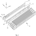
- FIG. 1 A perspective exploded view of a planar magnetizing fixture 10 according to an embodiment of the invention is shown in Fig. 1 .
- the magnetizing fixture 10 comprises a plurality of conducting portions 12, wherein the conducting portions 12 are prepared in such a way that every pair of adjacent conducting portions 12 is connected together at one end thereof such that a meandering pattern across the entire conducting portions or the entire fixture is created.
- the conducting portions 12 are preferably made of copper, which exhibits good electrical conductivity.
- planar magnetizing fixture 10 will be described using the coordinate system shown in Fig.1 .
- the Z-direction is referred to as an upper or top direction, while a direction opposite to the Z-direction is referred to as a lower or bottom direction.
- a person skilled in the art will understand that such relative terms are used to clarify the description and do not limit the scope of the present invention to any particular orientation.
- the conducting portions 12 are plate-shaped portions which extend in the X-direction, wherein the conducting portions 12 are preferably separate pieces which are electrically connected, preferably by plate-shaped conducting bridges 14, in particular copper pieces, wherein the conducting portions 12 are one by one stacked in the Y-direction.
- each conducting portion 12 preferably comprises one or more through holes 16, as well as one or more open slots 18, wherein each open slot 18 preferably extends from one through hole 16 to one side of the conducting portions 12.
- the slots may extend in the Z-direction to the lower side of the conducting portions 12.
- the open slots 18 are used to prevent any eddy currents from running around the hole 16, while the through holes 16 are cut in order to force the current to flow in a layer at the upper side of the conducting portions 12.
- the metal between the through holes 16 helps to hold the current carrying layer in place, which could thus not be bended by high current induced forces.
- the metal between the through holes 16 also helps with heat dissipation, because it provides a path for the heat to flow from the current-carrying layer where the heat is created by Joule heating to the opposite lower side of the conducting portions where there is a lot of metal material for the heat to spread to. In this way, the heat can be better and more efficiently dissipated.
- Each conducting portion 12 preferably further comprises at least one fastening hole 20 for fastening the conducting portion in the stack, e.g. two round through holes 20 which are respectively provided at both ends of the conducting portion 12.
- the fastening holes 20 may receive rods, for example fiber glass rods, to fix the stacked conducting portions together.
- An open slot also preferably extends from each fastening hole to one side of each conducting portion 12, in order to avoid or reduce eddy currents.
- Every pair of adjacent conducting portions 12 is preferably separated by at least one insulation layer 22, so that no other electrical contact is established except for the connecting point by the conducting bridge 14.
- the insulation layer 22 is for example made of glue, which is preferably lined with fiber glass so that even under large pressures it keeps a set thickness.
- Each insulation layer 22 also comprises at least one through hole aligned with the fastening hole 20 for stacking and fixing purposes.
- the field guide plates 24 amplify the magnetic field created by the current and help magnetize a sheet or layer which is placed at the meandering pattern above the fixture.
- the metal layers 24 preferably also comprise through holes aligned with the fastening holes 20 for fixing purpose.
- a plurality of open slots may be provided, preferably at positions distributed along the X-direction and each slot extending in Z-direction, for preventing eddy currents.
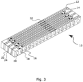
- Fig. 3 is an exemplary illustration of a current path created by the fixture.
- the direction of the current 32 is illustrated with arrows.
- the conducting portions are cut in such a way that the current is confined in a layer at the upper surface of the fixture 10.
- Fig. 4 shows a schematic cross-section view of the magnetizing fixture 10 with indicated current directions.
- An upper layer 36 at the surface of the fixture 10 which carries the major part of the current 32 is also illustrated.
- the magnetic field inside the dotted square 34 created by the current 32 is simulated by the software COMSOL and illustrated in Fig. 5 .
- the circular field lines correspond to the magnetic field 40 created by the current 32, reflecting the right-hand rule.
- a sheet or a laminated layer 38 which is placed above the upper surface of the fixture 10 is magnetized by the magnetic field 40.
- the short arrows 42 indicate the magnetic field at a certain height inside the sheet or layer and show a cycloidal pattern, magnetizing the sheet or laminated layer 38 above the fixture 10 into a continuous Halbach array-like pattern.
- the pattern shown in Fig. 5 repeats throughout the whole fixture.
- Fig. 6 and Fig. 7 illustrate two embodiments of an assembled planar magnetizing fixture.
- Fig. 6 shows a fixture 100 comprising stacked conducting portions 112 out of copper, conducting bridge 114 out of copper, insulation layers 122 as well as field guide plates 124 out of iron.
- the high mechanical strength of the stacking and the glue make it possible for this fixture 100 to withstand the high forces experienced during the magnetizing process.
- At least one rod, preferably two fiberglass rods 140 are inserted through the aligned fastening holes and other aligned holes at the ends of the conducting portions 112, conducting bridges 114, insulation layers 122 and field guide plates 124 such as to establish a rigid configuration and keep the stack from bending when compressed.
- the conducting portions 112 and other parts are preferably cut out from a sheet of corresponding thickness and material by electro-erosion or other method like laser cutting etc.
- the portions 112 are then stacked together and aligned along the rods 140.
- the stack may be squeezed and fixed together e.g. by screws 142 and the glue may be cured in an oven at about 120 °C for 3-4 hours.
- the glue may be cured in an oven at about 120 °C for 3-4 hours.
- the stack is able to resist high pressures applied on it.
- a pressure which is high enough to keep the fixture from delaminating is subsequently applied, which also helps to make a good contact between the conducting portions 112 and the conducting bridges 114 which form the current path.
- a realization of the fixture has for example a copper portion thickness of 1.5 mm and an iron layer thickness of 1.5 mm, resulting in a pole pitch of about 3.4 mm.
- the invention can be adapted by completely taking out the iron layers.
- a fixture 200 only comprises conducting portions 212, conducting bridges 214 and insulation layers 222, which also acts as spacer to set the pole width.
- the pole density can thus be significantly increased without losing structural properties.
- a realization of such a fixture 200 without field guide plates has for example a conducting portion thickness of 1.5 mm and a pole pitch of 1.8 mm.
- Fig. 8 illustrates a cross-section view of such a fixture 300 which comprises wedge-shaped conducting portions 312 which are preferably made of copper, insulation layers 322 e.g. made of glue, and field guide pieces which are preferably made of iron.
- the wedge-shaped conducting portions 312 are also preferably cut in such a way that the current 332 is confined in a layer 336 as close as possible to the inner surface of the fixture 300.
- An arc-shaped or cylindrical layer 338 is placed along the inner surface of the fixture 300 and can be magnetized into a multipolar pattern which is an approximate realization of a continuous circular Halbach array.
- a plate-shaped conducting portion of the magnetizing fixture is not restricted to be flat or rectangular plate-shaped as shown in Fig. 6 and Fig. 7 . Instead, other more sophisticated geometries can also be obtained and used.
- a wedge-shaped conducting portion of the magnetizing fixture is also not restricted to a wedge with flat, convex or concave surfaces as shown in Fig. 8 . It could also be a wedge with any geometry.
- Fig. 9 shows a further embodiment of the fixture 100' that can be used to create wave- or zig-zag-like stripe patterns, wherein each conducting portion 112' is shaped into a wave- or zig-zag-like plate.
- each field guide portion 124' as well as each insulation layer 122' is also shaped into a wave- or zig-zag-like plate accordingly.
- the shaping process could be realized before stacking by pressing each conducting plate 112' with an according die, so that the conducting plate 112' take on the shape of the die.
- the conducting plates 112' could also be formed into other plate-shape using other appropriate dies.
- the same shaping process also applies to the field guide portions 124' as well as the insulation layers 122', so that they could be accordingly stacked with the conducting portions 122' and if present, the conducting bridges 114' together to build up the fixture 100', preferably using fiber glass rods 140'. After being stacked, they are preferably further squeezed and firmly fixed together by screws 142'.
- a magnetizing fixture according to the invention can be used to magnetize any thin sheets or layers of magnetizable material, preferably 0.1 to 1 mm.
- One example is ski skins or ski bases which comprise layers magnetized by a fixture according to the invention.
- Fig. 10 shows a traditionally connected ski skin 450 and ski base 460.
- Ski skin 450 is usually made up of layers of different materials, namely a layer 451 which will be in contact with the snow and is for example made of velvet, a layer 453 which will contact the ski which is preferably made of rubber, and some other structural layers 452 in between, as illustrated in Fig. 10 .
- a layer of glue 470 above the rubber layer 453 is usually used to fasten the ski skin 450 to the ski base 460.
- the glue is not needed anymore for fastening the ski skin 550, as shown in Fig. 11 .
- magnetizable particles are mixed directly into the rubber layer 553.
- other materials such as silicone can also be used instead of rubber.
- magnetizable particles are then directly mixed into silicone.
- magnetic forces are used to fasten the ski skin 550 to the ski base 560.
- the magnetizable particles are randomly oriented and have randomly oriented grains. Thus they do not create any significant magnetic fields.
- a magnetizing fixture according to the invention is able to create a magnetic field of about 2 Tesla which can saturate the magnetic particles, which will retain permanently a portion of this magnetization, inside the rubber layer 553 of the ski skin 550.
- the rubber layer 553 can thus be magnetized by the fixture into an approximation of a continuous Halbach-array, which provides significant magnetic forces in a direction perpendicular to the surface of the rubber layer 553 as well as inside the layer in the direction perpendicular to the stripes.
- a similar magnetic layer 562 can be introduced into the ski base 560 as well.
- the ski base 560 is usually made of a 1.2 mm layer of HDPE.
- a thin layer of HDPE can be mixed with magnetizable particles and integrated into the HDPE layer of the ski base 560, resulting in a sandwich-shaped three layers in the ski base 560.
- the first layer 561 is a pure HDPE layer for gliding
- the second layer 562 is a magnetic layer of HDPE for fastening purpose
- the third layer 563 is made of pure HDPE in order to reach the 1.2 mm thickness without adding too much additional weight.
- the magnetic layer 562 of the ski base can be magnetized using the same fixture for the ski base. However, it is up to a manufacturer or a person skilled in the art to decide whether both ski skin and ski base are magnetized using the fixture or only one of them is magnetized in this way.
- a magnetizing fixture according to the invention is however not restricted to the magnetization of ski skins and ski bases but can be applied to anything that uses thin sheets or layers of magnetizable materials such as Nd-Fe-B.
- it can be used to magnetize thin sheets for fastening purposes like fastening phones to docking stations, or one can also imagine planar fridge magnets.
- another application would be applying magnetizable particles into textiles and magnetizing them by a fixture according to the invention, so that magnetic forces can be used to close or tighten garments, instead of using buttons or zippers.
- a cylindrical embodiment as for example illustrated in Fig.
- a fixture according to the invention can also be used to create an approximate Halbach array in a stator of an electric motor, for example a stepper motor, wherein magnetizing the circular stator into a continuous multipolar pattern would significantly simplify the assembly of the stator.
Landscapes
- Engineering & Computer Science (AREA)
- Power Engineering (AREA)
- Physics & Mathematics (AREA)
- Electromagnetism (AREA)
- Permanent Field Magnets Of Synchronous Machinery (AREA)
- Magnetic Treatment Devices (AREA)
- Dynamo-Electric Clutches, Dynamo-Electric Brakes (AREA)
Claims (12)
- Dispositif de magnétisation (10, 100, 200, 300, 100') comprenant des parties conductrices (12, 112, 212, 312, 112'), de préférence en cuivre, dans lequel les parties conductrices (12, 112, 212, 312, 112') sont préparées de telle sorte qu'elles forment un motif sinueux,dans laquelle chaque partie conductrice (12, 112, 212, 312, 112') comprend au moins un trou traversant (16),dans laquelle chaque partie conductrice (12, 112, 212, 312, 112') comprend au moins une fente ouverte (18) qui s'étend sur un côté de la partie conductrice,dans laquelle la au moins une fente ouverte (18) s'étend respectivement de l'au moins un trou traversant (16) à un côté de la partie conductrice, etcaractérisé par le fait que les parties conductrices (12, 112, 212, 312, 112') ont la forme d'une plaque ou d'un coin.
- Dispositif de magnétisation (10, 100, 200, 300, 100') selon la revendication 1, caractérisé en ce que les parties conductrices (12, 112, 212, 312, 112') sont des pièces séparées qui sont connectées électriquement l'une à l'autre.
- Dispositif de magnétisation (10, 100, 200, 300, 100') selon la revendication 2, caractérisé en ce que les parties conductrices (12, 112, 212, 312, 112') sont reliées électriquement par un pont conducteur (14, 114, 214, 114'), de préférence une pièce de cuivre.
- Installation de magnétisation (10, 100, 200, 300, 100') selon l'une des revendications précédentes, caractérisée en ce que les parties conductrices (12, 112, 212, 312, 112') sont empilées et fixées mécaniquement ensemble.
- Dispositif de magnétisation (10, 100, 200, 300, 100') selon l'une des revendications précédentes, caractérisé en ce qu'au moins une couche d'isolation (22, 122, 222, 322, 122') est prévue entre deux portions conductrices adjacentes (12, 112, 212, 312, 112'), la couche d'isolation (22, 122, 222, 322, 122') étant de préférence une couche de colle, la couche de colle étant plus préférentiellement doublée de fibre de verre.
- Dispositif de magnétisation (10, 100, 300, 100') selon la revendication 5, caractérisé en ce qu'au moins une portion de guidage de champ (24, 124, 324, 124'), contenant de préférence du fer, est prévue entre deux portions conductrices adjacentes (12, 112, 312, 112').
- Dispositif de magnétisation (10, 100, 300, 100') selon la revendication 6, dans lequel au moins une partie de guidage de champ (24, 124, 324, 124') comprend au moins une fente ouverte qui s'étend sur un côté de la partie de guidage de champ.
- Dispositif de magnétisation (10, 100, 300, 100') selon l'une des revendications précédentes, caractérisé en ce que le dispositif de magnétisation comprend en outre un moyen de refroidissement.
- Procédé de magnétisation d'une couche, comprenant :- Appliquer la couche au niveau des méandres d'un dispositif de magnétisation (10, 100, 200, 300, 100') selon l'une des revendications précédentes,- Appliquer une source de courant à l'appareil de magnétisation (10, 100, 200, 300, 100') de manière à ce qu'un courant circule à travers les méandres.
- Peau de ski (550) comprenant une couche (553) magnétisée par le procédé selon la revendication 9.
- Base de ski (560) comprenant une couche (562) magnétisée par le procédé selon la revendication 9.
- Ski comprenant une peau de ski (550) et une base de ski (560), dans lequel la peau de ski (550) comprend une couche (553) magnétisée par la méthode selon la revendication 9 et/ou une base de ski (560) comprend une couche (562) magnétisée par la méthode selon la revendication 9, dans lequel la peau de ski (550) et la base de ski (560) sont magnétiquement connectées.
Applications Claiming Priority (1)
| Application Number | Priority Date | Filing Date | Title |
|---|---|---|---|
| PCT/EP2019/061425 WO2020224747A1 (fr) | 2019-05-03 | 2019-05-03 | Appareil de magnétisation multipolaire pour matériaux à haute coercivité |
Publications (3)
| Publication Number | Publication Date |
|---|---|
| EP3963607A1 EP3963607A1 (fr) | 2022-03-09 |
| EP3963607B1 true EP3963607B1 (fr) | 2025-03-19 |
| EP3963607C0 EP3963607C0 (fr) | 2025-03-19 |
Family
ID=66440042
Family Applications (1)
| Application Number | Title | Priority Date | Filing Date |
|---|---|---|---|
| EP19722584.0A Active EP3963607B1 (fr) | 2019-05-03 | 2019-05-03 | Appareil de magnétisation multipolaire pour matériaux à haute coercivité |
Country Status (4)
| Country | Link |
|---|---|
| EP (1) | EP3963607B1 (fr) |
| CN (1) | CN113678214B (fr) |
| ES (1) | ES3024132T3 (fr) |
| WO (1) | WO2020224747A1 (fr) |
Families Citing this family (1)
| Publication number | Priority date | Publication date | Assignee | Title |
|---|---|---|---|---|
| CN114566348B (zh) * | 2022-04-08 | 2022-11-11 | 浙江大学 | 一种全局加热的多极磁化方法和装置 |
Family Cites Families (16)
| Publication number | Priority date | Publication date | Assignee | Title |
|---|---|---|---|---|
| US3474368A (en) * | 1967-08-01 | 1969-10-21 | R F L Ind Inc | Magnet charging fixture |
| US3480894A (en) * | 1968-02-28 | 1969-11-25 | Kevin E Joyce | Magnetic edge protector for a ski |
| DE3506757A1 (de) * | 1984-09-22 | 1986-08-28 | Erich Dr.-Ing. 5300 Bonn Steingroever | Magnetisiervorrichtung fuer dauermagnete |
| DE3610690C5 (de) * | 1986-03-29 | 2005-12-08 | Magnet-Physik Dr. Steingroever Gmbh | Magnetspule mit scheibenförmigem Stromleiter |
| US5063367A (en) * | 1990-09-04 | 1991-11-05 | Eastman Kodak Company | Method and apparatus for producing complex magnetization patterns in hard magnetic materials |
| DE4301771C2 (de) * | 1993-01-23 | 1995-06-29 | Steingroever Magnet Physik | Magnetisiervorrichtung für Dauermagnet-Folien mit streifenförmigen Polen |
| US6566731B2 (en) * | 1999-02-26 | 2003-05-20 | Micron Technology, Inc. | Open pattern inductor |
| JP2002313628A (ja) * | 2001-04-16 | 2002-10-25 | Shimizu Corp | 建築構造物用脱磁装置の脱磁コイル |
| US20070010702A1 (en) * | 2003-04-08 | 2007-01-11 | Xingwu Wang | Medical device with low magnetic susceptibility |
| SI21630A (sl) * | 2003-09-05 | 2005-04-30 | Iskra Mehanizmi, Industrija Mehanizmov, Aparatov In Sistemov D.D. | Mnogopolna magnetilna naprava in postopek izdelave |
| JP2009278168A (ja) * | 2008-05-12 | 2009-11-26 | Mitsubishi Electric Engineering Co Ltd | 電磁変換器 |
| GB2502084A (en) * | 2012-05-14 | 2013-11-20 | Bombardier Transp Gmbh | Arrangement for providing vehicles with energy comprising magnetisable material |
| US20170305184A1 (en) * | 2014-11-27 | 2017-10-26 | Sicpa Holdings Sa | Devices and methods for orienting platelet-shaped magnetic or magnetizable pigment particles |
| CN105895322A (zh) * | 2014-12-29 | 2016-08-24 | 上海稳得新能源科技有限公司 | 非叠片型铁心节能电抗器 |
| US10607759B2 (en) * | 2017-03-31 | 2020-03-31 | International Business Machines Corporation | Method of fabricating a laminated stack of magnetic inductor |
| HUE054728T2 (hu) * | 2017-08-03 | 2021-09-28 | Pomoca S A | Egyirányú súrolóanyag |
-
2019
- 2019-05-03 ES ES19722584T patent/ES3024132T3/es active Active
- 2019-05-03 CN CN201980095310.7A patent/CN113678214B/zh active Active
- 2019-05-03 WO PCT/EP2019/061425 patent/WO2020224747A1/fr not_active Ceased
- 2019-05-03 EP EP19722584.0A patent/EP3963607B1/fr active Active
Also Published As
| Publication number | Publication date |
|---|---|
| CN113678214A (zh) | 2021-11-19 |
| EP3963607A1 (fr) | 2022-03-09 |
| CN113678214B (zh) | 2025-09-23 |
| ES3024132T3 (en) | 2025-06-03 |
| EP3963607C0 (fr) | 2025-03-19 |
| WO2020224747A1 (fr) | 2020-11-12 |
Similar Documents
| Publication | Publication Date | Title |
|---|---|---|
| EP2722968B1 (fr) | Rotor pour machine électrique rotative, machine électrique rotative, et procédé de production d'un rotor pour machine électrique rotative | |
| TWI404083B (zh) | 利用磁性基礎之高能量電感器 | |
| KR20090104821A (ko) | 스티어링 미러 응용들을 위한 고대역폭 선형 액추에이터 | |
| US20080048505A1 (en) | Coreless Linear Motor | |
| EP0192331A1 (fr) | Electro-aimant | |
| EP1365498A3 (fr) | Actionneur linéaire à bobine mobile, appareil utilisant cet actionneur et méthode de fabrication de l'actionneur | |
| US20140320247A1 (en) | System for concentrating magnetic flux of a multi-pole magnetic structure | |
| EP2692042A1 (fr) | Porte-aimant pour actionneur à aimants mobiles | |
| EP3963607A1 (fr) | Appareil de magnétisation multipolaire pour matériaux à haute coercivité | |
| KR20170027671A (ko) | 영구 자석 자기 회로의 제조 방법 | |
| CN203352411U (zh) | 直线滑动器 | |
| US12249889B2 (en) | Magnetic-geared motor with divisional spacers | |
| JP5589507B2 (ja) | リニア駆動装置の可動子及び固定子 | |
| CN100434928C (zh) | 一种可用于磁共振设备的磁场发生系统 | |
| US5097239A (en) | Fixture and method for multi-pole magnetization of a magnetizable part | |
| JP4214736B2 (ja) | Mri用磁界発生装置 | |
| US20230103189A1 (en) | Magnet with Multiple Discs | |
| US20120248898A1 (en) | Moving Magnet Actuator Magnet Carrier | |
| US20210110966A1 (en) | Magnet with multiple discs | |
| JP5515964B2 (ja) | 着磁コイルおよびその製造方法 | |
| JP3073933B2 (ja) | Mri用磁界発生装置 | |
| KR102529748B1 (ko) | 착자 장치 | |
| JP3848885B2 (ja) | 駆動装置 | |
| JP4030695B2 (ja) | 挿入光源 | |
| US20220208427A1 (en) | A multipole magnet |
Legal Events
| Date | Code | Title | Description |
|---|---|---|---|
| STAA | Information on the status of an ep patent application or granted ep patent |
Free format text: STATUS: UNKNOWN |
|
| STAA | Information on the status of an ep patent application or granted ep patent |
Free format text: STATUS: THE INTERNATIONAL PUBLICATION HAS BEEN MADE |
|
| PUAI | Public reference made under article 153(3) epc to a published international application that has entered the european phase |
Free format text: ORIGINAL CODE: 0009012 |
|
| STAA | Information on the status of an ep patent application or granted ep patent |
Free format text: STATUS: REQUEST FOR EXAMINATION WAS MADE |
|
| 17P | Request for examination filed |
Effective date: 20211122 |
|
| AK | Designated contracting states |
Kind code of ref document: A1 Designated state(s): AL AT BE BG CH CY CZ DE DK EE ES FI FR GB GR HR HU IE IS IT LI LT LU LV MC MK MT NL NO PL PT RO RS SE SI SK SM TR |
|
| DAV | Request for validation of the european patent (deleted) | ||
| DAX | Request for extension of the european patent (deleted) | ||
| STAA | Information on the status of an ep patent application or granted ep patent |
Free format text: STATUS: EXAMINATION IS IN PROGRESS |
|
| 17Q | First examination report despatched |
Effective date: 20240430 |
|
| GRAP | Despatch of communication of intention to grant a patent |
Free format text: ORIGINAL CODE: EPIDOSNIGR1 |
|
| STAA | Information on the status of an ep patent application or granted ep patent |
Free format text: STATUS: GRANT OF PATENT IS INTENDED |
|
| INTG | Intention to grant announced |
Effective date: 20241010 |
|
| GRAS | Grant fee paid |
Free format text: ORIGINAL CODE: EPIDOSNIGR3 |
|
| GRAA | (expected) grant |
Free format text: ORIGINAL CODE: 0009210 |
|
| STAA | Information on the status of an ep patent application or granted ep patent |
Free format text: STATUS: THE PATENT HAS BEEN GRANTED |
|
| AK | Designated contracting states |
Kind code of ref document: B1 Designated state(s): AL AT BE BG CH CY CZ DE DK EE ES FI FR GB GR HR HU IE IS IT LI LT LU LV MC MK MT NL NO PL PT RO RS SE SI SK SM TR |
|
| RAP3 | Party data changed (applicant data changed or rights of an application transferred) |
Owner name: POMOCA S.A. |
|
| REG | Reference to a national code |
Ref country code: GB Ref legal event code: FG4D |
|
| REG | Reference to a national code |
Ref country code: CH Ref legal event code: EP |
|
| REG | Reference to a national code |
Ref country code: DE Ref legal event code: R096 Ref document number: 602019067459 Country of ref document: DE |
|
| REG | Reference to a national code |
Ref country code: IE Ref legal event code: FG4D |
|
| U01 | Request for unitary effect filed |
Effective date: 20250319 |
|
| U07 | Unitary effect registered |
Designated state(s): AT BE BG DE DK EE FI FR IT LT LU LV MT NL PT RO SE SI Effective date: 20250325 |
|
| REG | Reference to a national code |
Ref country code: ES Ref legal event code: FG2A Ref document number: 3024132 Country of ref document: ES Kind code of ref document: T3 Effective date: 20250603 |
|
| U20 | Renewal fee for the european patent with unitary effect paid |
Year of fee payment: 7 Effective date: 20250428 |
|
| PG25 | Lapsed in a contracting state [announced via postgrant information from national office to epo] |
Ref country code: RS Free format text: LAPSE BECAUSE OF FAILURE TO SUBMIT A TRANSLATION OF THE DESCRIPTION OR TO PAY THE FEE WITHIN THE PRESCRIBED TIME-LIMIT Effective date: 20250619 |
|
| PGFP | Annual fee paid to national office [announced via postgrant information from national office to epo] |
Ref country code: GB Payment date: 20250527 Year of fee payment: 7 |
|
| PGFP | Annual fee paid to national office [announced via postgrant information from national office to epo] |
Ref country code: NO Payment date: 20250523 Year of fee payment: 7 |
|
| PG25 | Lapsed in a contracting state [announced via postgrant information from national office to epo] |
Ref country code: HR Free format text: LAPSE BECAUSE OF FAILURE TO SUBMIT A TRANSLATION OF THE DESCRIPTION OR TO PAY THE FEE WITHIN THE PRESCRIBED TIME-LIMIT Effective date: 20250319 |
|
| PG25 | Lapsed in a contracting state [announced via postgrant information from national office to epo] |
Ref country code: GR Free format text: LAPSE BECAUSE OF FAILURE TO SUBMIT A TRANSLATION OF THE DESCRIPTION OR TO PAY THE FEE WITHIN THE PRESCRIBED TIME-LIMIT Effective date: 20250620 |
|
| PGFP | Annual fee paid to national office [announced via postgrant information from national office to epo] |
Ref country code: CH Payment date: 20250601 Year of fee payment: 7 |
|
| PG25 | Lapsed in a contracting state [announced via postgrant information from national office to epo] |
Ref country code: SM Free format text: LAPSE BECAUSE OF FAILURE TO SUBMIT A TRANSLATION OF THE DESCRIPTION OR TO PAY THE FEE WITHIN THE PRESCRIBED TIME-LIMIT Effective date: 20250319 |
|
| PGFP | Annual fee paid to national office [announced via postgrant information from national office to epo] |
Ref country code: ES Payment date: 20250630 Year of fee payment: 7 |
|
| PG25 | Lapsed in a contracting state [announced via postgrant information from national office to epo] |
Ref country code: PL Free format text: LAPSE BECAUSE OF FAILURE TO SUBMIT A TRANSLATION OF THE DESCRIPTION OR TO PAY THE FEE WITHIN THE PRESCRIBED TIME-LIMIT Effective date: 20250319 |
|
| PG25 | Lapsed in a contracting state [announced via postgrant information from national office to epo] |
Ref country code: CZ Free format text: LAPSE BECAUSE OF FAILURE TO SUBMIT A TRANSLATION OF THE DESCRIPTION OR TO PAY THE FEE WITHIN THE PRESCRIBED TIME-LIMIT Effective date: 20250319 |
|
| PG25 | Lapsed in a contracting state [announced via postgrant information from national office to epo] |
Ref country code: SK Free format text: LAPSE BECAUSE OF FAILURE TO SUBMIT A TRANSLATION OF THE DESCRIPTION OR TO PAY THE FEE WITHIN THE PRESCRIBED TIME-LIMIT Effective date: 20250319 |
|
| PG25 | Lapsed in a contracting state [announced via postgrant information from national office to epo] |
Ref country code: IS Free format text: LAPSE BECAUSE OF FAILURE TO SUBMIT A TRANSLATION OF THE DESCRIPTION OR TO PAY THE FEE WITHIN THE PRESCRIBED TIME-LIMIT Effective date: 20250719 |
|
| PLBE | No opposition filed within time limit |
Free format text: ORIGINAL CODE: 0009261 |
|
| STAA | Information on the status of an ep patent application or granted ep patent |
Free format text: STATUS: NO OPPOSITION FILED WITHIN TIME LIMIT |
|
| REG | Reference to a national code |
Ref country code: CH Ref legal event code: L10 Free format text: ST27 STATUS EVENT CODE: U-0-0-L10-L00 (AS PROVIDED BY THE NATIONAL OFFICE) Effective date: 20260128 |
|
| PG25 | Lapsed in a contracting state [announced via postgrant information from national office to epo] |
Ref country code: MC Free format text: LAPSE BECAUSE OF FAILURE TO SUBMIT A TRANSLATION OF THE DESCRIPTION OR TO PAY THE FEE WITHIN THE PRESCRIBED TIME-LIMIT Effective date: 20250319 |
|
| 26N | No opposition filed |
Effective date: 20251222 |
|
| PG25 | Lapsed in a contracting state [announced via postgrant information from national office to epo] |
Ref country code: IE Free format text: LAPSE BECAUSE OF NON-PAYMENT OF DUE FEES Effective date: 20250503 |