EP3964149B1 - Vorrichtung zur befestigung und evakuierung - Google Patents
Vorrichtung zur befestigung und evakuierung Download PDFInfo
- Publication number
- EP3964149B1 EP3964149B1 EP21202994.6A EP21202994A EP3964149B1 EP 3964149 B1 EP3964149 B1 EP 3964149B1 EP 21202994 A EP21202994 A EP 21202994A EP 3964149 B1 EP3964149 B1 EP 3964149B1
- Authority
- EP
- European Patent Office
- Prior art keywords
- pump
- operable
- blower
- filter
- fluid
- Prior art date
- Legal status (The legal status is an assumption and is not a legal conclusion. Google has not performed a legal analysis and makes no representation as to the accuracy of the status listed.)
- Active
Links
Images


Classifications
-
- B—PERFORMING OPERATIONS; TRANSPORTING
- B08—CLEANING
- B08B—CLEANING IN GENERAL; PREVENTION OF FOULING IN GENERAL
- B08B15/00—Preventing escape of dirt or fumes from the area where they are produced; Collecting or removing dirt or fumes from that area
- B08B15/007—Fume suction nozzles arranged on a closed or semi-closed surface, e.g. on a circular, ring-shaped or rectangular surface adjacent the area where fumes are produced
-
- A—HUMAN NECESSITIES
- A61—MEDICAL OR VETERINARY SCIENCE; HYGIENE
- A61B—DIAGNOSIS; SURGERY; IDENTIFICATION
- A61B18/00—Surgical instruments, devices or methods for transferring non-mechanical forms of energy to or from the body
-
- A—HUMAN NECESSITIES
- A61—MEDICAL OR VETERINARY SCIENCE; HYGIENE
- A61B—DIAGNOSIS; SURGERY; IDENTIFICATION
- A61B90/00—Instruments, implements or accessories specially adapted for surgery or diagnosis and not covered by any of the groups A61B1/00 - A61B50/00, e.g. for luxation treatment or for protecting wound edges
-
- B—PERFORMING OPERATIONS; TRANSPORTING
- B01—PHYSICAL OR CHEMICAL PROCESSES OR APPARATUS IN GENERAL
- B01D—SEPARATION
- B01D46/00—Filters or filtering processes specially modified for separating dispersed particles from gases or vapours
- B01D46/0039—Filters or filtering processes specially modified for separating dispersed particles from gases or vapours with flow guiding by feed or discharge devices
- B01D46/0041—Filters or filtering processes specially modified for separating dispersed particles from gases or vapours with flow guiding by feed or discharge devices for feeding
-
- B—PERFORMING OPERATIONS; TRANSPORTING
- B08—CLEANING
- B08B—CLEANING IN GENERAL; PREVENTION OF FOULING IN GENERAL
- B08B15/00—Preventing escape of dirt or fumes from the area where they are produced; Collecting or removing dirt or fumes from that area
-
- F—MECHANICAL ENGINEERING; LIGHTING; HEATING; WEAPONS; BLASTING
- F24—HEATING; RANGES; VENTILATING
- F24F—AIR-CONDITIONING; AIR-HUMIDIFICATION; VENTILATION; USE OF AIR CURRENTS FOR SCREENING
- F24F7/00—Ventilation
- F24F7/04—Ventilation with ducting systems, e.g. by double walls; with natural circulation
- F24F7/06—Ventilation with ducting systems, e.g. by double walls; with natural circulation with forced air circulation, e.g. by fan positioning of a ventilator in or against a conduit
- F24F7/08—Ventilation with ducting systems, e.g. by double walls; with natural circulation with forced air circulation, e.g. by fan positioning of a ventilator in or against a conduit with separate ducts for supplied and exhausted air with provisions for reversal of the input and output systems
-
- H—ELECTRICITY
- H01—ELECTRIC ELEMENTS
- H01R—ELECTRICALLY-CONDUCTIVE CONNECTIONS; STRUCTURAL ASSOCIATIONS OF A PLURALITY OF MUTUALLY-INSULATED ELECTRICAL CONNECTING ELEMENTS; COUPLING DEVICES; CURRENT COLLECTORS
- H01R24/00—Two-part coupling devices, or either of their cooperating parts, characterised by their overall structure
- H01R24/66—Two-part coupling devices, or either of their cooperating parts, characterised by their overall structure with pins, blades or analogous contacts and secured to apparatus or structure, e.g. to a wall
- H01R24/68—Two-part coupling devices, or either of their cooperating parts, characterised by their overall structure with pins, blades or analogous contacts and secured to apparatus or structure, e.g. to a wall mounted on directly pluggable apparatus
-
- A—HUMAN NECESSITIES
- A61—MEDICAL OR VETERINARY SCIENCE; HYGIENE
- A61B—DIAGNOSIS; SURGERY; IDENTIFICATION
- A61B18/00—Surgical instruments, devices or methods for transferring non-mechanical forms of energy to or from the body
- A61B18/04—Surgical instruments, devices or methods for transferring non-mechanical forms of energy to or from the body by heating
- A61B18/12—Surgical instruments, devices or methods for transferring non-mechanical forms of energy to or from the body by heating by passing a current through the tissue to be heated, e.g. high-frequency current
- A61B18/14—Probes or electrodes therefor
-
- A—HUMAN NECESSITIES
- A61—MEDICAL OR VETERINARY SCIENCE; HYGIENE
- A61B—DIAGNOSIS; SURGERY; IDENTIFICATION
- A61B18/00—Surgical instruments, devices or methods for transferring non-mechanical forms of energy to or from the body
- A61B18/18—Surgical instruments, devices or methods for transferring non-mechanical forms of energy to or from the body by applying electromagnetic radiation, e.g. microwaves
- A61B18/20—Surgical instruments, devices or methods for transferring non-mechanical forms of energy to or from the body by applying electromagnetic radiation, e.g. microwaves using laser
-
- A—HUMAN NECESSITIES
- A61—MEDICAL OR VETERINARY SCIENCE; HYGIENE
- A61B—DIAGNOSIS; SURGERY; IDENTIFICATION
- A61B17/00—Surgical instruments, devices or methods
- A61B2017/00477—Coupling
-
- A—HUMAN NECESSITIES
- A61—MEDICAL OR VETERINARY SCIENCE; HYGIENE
- A61B—DIAGNOSIS; SURGERY; IDENTIFICATION
- A61B17/00—Surgical instruments, devices or methods
- A61B2017/00477—Coupling
- A61B2017/00486—Adaptors for coupling parts with incompatible geometries
-
- A—HUMAN NECESSITIES
- A61—MEDICAL OR VETERINARY SCIENCE; HYGIENE
- A61B—DIAGNOSIS; SURGERY; IDENTIFICATION
- A61B18/00—Surgical instruments, devices or methods for transferring non-mechanical forms of energy to or from the body
- A61B2018/00053—Mechanical features of the instrument of device
- A61B2018/00172—Connectors and adapters therefor
- A61B2018/00178—Electrical connectors
-
- A—HUMAN NECESSITIES
- A61—MEDICAL OR VETERINARY SCIENCE; HYGIENE
- A61B—DIAGNOSIS; SURGERY; IDENTIFICATION
- A61B2218/00—Details of surgical instruments, devices or methods for transferring non-mechanical forms of energy to or from the body
- A61B2218/001—Details of surgical instruments, devices or methods for transferring non-mechanical forms of energy to or from the body having means for irrigation and/or aspiration of substances to and/or from the surgical site
- A61B2218/007—Aspiration
- A61B2218/008—Aspiration for smoke evacuation
-
- B—PERFORMING OPERATIONS; TRANSPORTING
- B01—PHYSICAL OR CHEMICAL PROCESSES OR APPARATUS IN GENERAL
- B01D—SEPARATION
- B01D2279/00—Filters adapted for separating dispersed particles from gases or vapours specially modified for specific uses
- B01D2279/35—Filters adapted for separating dispersed particles from gases or vapours specially modified for specific uses for venting arrangements
-
- B—PERFORMING OPERATIONS; TRANSPORTING
- B08—CLEANING
- B08B—CLEANING IN GENERAL; PREVENTION OF FOULING IN GENERAL
- B08B15/00—Preventing escape of dirt or fumes from the area where they are produced; Collecting or removing dirt or fumes from that area
- B08B15/04—Preventing escape of dirt or fumes from the area where they are produced; Collecting or removing dirt or fumes from that area from a small area, e.g. a tool
-
- H—ELECTRICITY
- H01—ELECTRIC ELEMENTS
- H01R—ELECTRICALLY-CONDUCTIVE CONNECTIONS; STRUCTURAL ASSOCIATIONS OF A PLURALITY OF MUTUALLY-INSULATED ELECTRICAL CONNECTING ELEMENTS; COUPLING DEVICES; CURRENT COLLECTORS
- H01R2103/00—Two poles
Definitions
- the present invention relates generally to the field of surgical smoke evacuation, and more particularly to a dual surgical smoke evacuation and universal hose attachment system and a method of using such a system for safe and efficient filtration of smoke plume generated by laser-surgical, electrosurgical, radiosurgical, cautery, hyfrecators and electrocautery devices.
- Surgical smoke evacuation systems are designed to capture the smoke and plume generated during surgical procedures in which there is thermal destruction of tissue or bone.
- the plume from vaporized tissue contains small particles and gases that could be potentially hazardous. If not evacuated the materials can become airborne and deposit in the respiratory tracts of the surgical team.
- the type of surgical instruments, the characteristics of tissue, and the surgeon's technique affect the quantity and characteristics of the smoke plume.
- US 5 971 977 A discloses a surgical laser smoke plume evacuator which includes an evacuator body which is formed to a shape which is suitable for placement in normal use position substantially entirely around and adjacent to a tissue site upon which laser surgery is to be performed.
- the evacuator body has structure for removing smoke therethrough, and a smoke exit portion in communication with and extending from the evacuator body.
- the smoke exit portion is connectable to vacuum source, to thereby apply a vacuum to the evacuator body and cause smoke which is created at a surgical site during surgery to be removed from the surgical site through the evacuator body and the smoke exit portion.
- US 2014/0338529 A1 discloses a smoke evacuator that draws smoke generated during a medical surgical procedure away from the site at which the smoke is generated.
- the smoke evacuator includes a pump that draws air into a filter.
- a sensor internal to the filter monitors the smoke in the air stream drawn through the filter. Normally the pump runs at a low speed, a speed sufficient to draw some air in the filter.
- the sensor detects the presence of an appreciable amount of smoke in the air stream the sensor sends a signal indicating the air stream is in this state to the pump controller.
- the controller then increases the pump speed to result in a like increase in the volume of air drawn through the smoke evacuator. Since the sensor is contained in the filter, a new sensor is installed in the system each time a new filter is installed.
- a second exemplary embodiment of the present disclosure provides an apparatus for evacuation.
- the apparatus includes a housing having an opening, and a motor maintained within the housing, the motor operable to urge a fluid to pass through the opening.
- the apparatus further includes an adjustable element maintained within the opening, the adjustable element operable to change a size of the opening to a plurality of different diameters, and a knob moveably affixed to the housing, the knob operable to change the adjustable element to the plurality of different diameters.
- a third exemplary embodiment of the present disclosure provides an apparatus for evacuation.
- the apparatus includes a blower having a housing that maintains a motor, a user interface, an opening, a blower power supply, a filter, a blower connector, and an adjustable element, the motor operable to urge a fluid to pass through the opening and the adjustable element, the filter operable to filter extraneous materials from the fluid that passes through the opening and the adjustable element, the adjustable element operable to change a size of the opening to a plurality of different diameters, the user interface operable to control the motor.
- the terms “horizontal”, “vertical”, “left”, “right”, “up” and “down”, as well as adjectival and adverbial derivatives thereof, simply refer to the orientation of the illustrated structure as the particular drawing figure faces the reader.
- the terms “inwardly” and “outwardly” generally refer to the orientation of a surface relative to its axis of elongation, or of rotation, as appropriate.
- Embodiments of the present disclosure provide an evacuation unit having housing that maintains a motor.
- the housing has an opening with an adjustable element (e.g., a mechanical iris, rotatable plate, etc.) that is operable to change the diameter of the opening such that the opening with the adjustable element can be removeably affixed to a tube or hose to create a sealed interface between the opening, the adjustable element and the tube or hose.
- the motor is operable to urge or evacuate a fluid (e.g., smoke or air) from a surgical site through the tube or hose and the opening.
- a fluid e.g., smoke or air
- Embodiments of the present disclosure also provide a blower unit and a pump unit that are each operable separately to evacuate or pump a fluid (e.g., smoke or air) from a surgical site.
- a fluid e.g., smoke or air
- Embodiments further provide that the blower unit and the pump unit can be operably affixed to one another such that they can share the use of each other's filter and/or power and/or user interface.
- this invention provides a universal hose attachment mechanism 20 (also referred to as an adjustable element) that adjusts to receive hoses having different diameters (e.g., 9.53 mm, 6.35 mm or 22,23 mm (3/8": 1/4"; or 7/8")).
- a universal hose attachment mechanism 20 also referred to as an adjustable element
- adjusts to receive hoses having different diameters e.g., 9.53 mm, 6.35 mm or 22,23 mm (3/8": 1/4"; or 7/8").
- the attachment mechanism 20 has a central opening 23 for receiving a tube or hose.
- a knob 26 may be provided on the front panel 29 of the smoke evacuator 32. Pushing the knob 26 along a raceway 35 disposed in the panel 29, in the direction of arrow 38, causes a mechanical iris 41 ( FIG. 2 ) to close around the tube inside the opening 23. Turning to FIG. 2 , when the knob 26 is pushed toward the end of the raceway 35, the opening 23 is substantially closed.
- the mechanical iris 41 is formed from a plurality of curved panels 44 that are constructed from a flexible material capable of sealing the outside surface of the tube.
- the iris 41 is constructed from the curved panels 44 in a known manner and the position of the iris 41 may be adjusted by means of a gear or the like as will be evident to those of ordinary skill in the art based on this disclosure.
- the integration of a mechanical iris 41 into the hose inlet for a smoke evacuation system provides numerous advantages including the ability to easily interchange different diameter tubing into the smoke evacuator system.
- an alternate embodiment of the universal hose attachment mechanism provides a mechanism 50 with a central opening 53.
- the central opening 53 receives a flexible insert 55 ( FIG. 4 ) that is capable of receiving a tube.
- a knob 56 is turned which turns an internal gear.
- the gear is mechanically connected to a sleeve 57 surrounding the flexible insert 55.
- the knob 56 is turned the gear causes the sleeve 57 to be tightened around the flexible insert 55.
- the tightening of the sleeve 57 causes the flexible insert 55 to compress around the tube 54 to seal it for use.
- FIG. 5 another alternative embodiment of the universal hose attachment mechanism is shown.
- the attachment mechanism 60 has a knob 63 connected to a rotating plate 66 having a plurality of openings 69a, 69b, and 69c disposed therein. Rotation of the knob 63 causes the plate 66 to turn which brings one of the openings 69a, 69b, and 69c on the plate 66 into registry with an opening in the front panel 72 of the smoke evacuation system 75.
- a dual surgical smoke evacuator system 100 includes a blower unit 103 with a blower motor 104 and a pump unit 106 with a pump 107.
- Each unit 103, 106 has separate power sources, interfaces and filters.
- Blowers and pumps suitable for smoke evacuation systems are known to those of ordinary skill in the art, and specific applications where a blower or pump is suitable are also known. For example, higher volume, lower pressure applications may be suitable for a blower, and a higher pressure, lower volume application may be suitable for a pump.
- the units 103, 106 are shown separate with a first power supply 109 for the blower unit 103 and a second power supply 112 for the pump unit 106.
- the blower unit 103 has a user interface 115 which allows for setting parameters associated with the blower unit 103 such as the speed of the motor.
- the pump unit 106 has a user interface 118 that provides for control of the pump unit 106 by the user.
- the blower unit 103 has a filter assembly 121, and the pump unit 106 has a filter assembly 124.
- the two units 103, 106 may be physically combined into a single attached system. When the units 103, 106 are attached, they form a dual smoke evacuation system that is capable of providing for smoke evacuation from either a blower unit 103 or a pump unit 106 depending on the application and the system requirements.
- the blower unit 103 and pump unit 106 may be provided with mechanical connectors 130a and 130b such as male/female connectors on the housing to provide for detachably connecting the units.
- the units 103, 106 may be provided with a universal hose attachment mechanism 138 as described above for receiving tubes having different diameters for different smoke removal applications and flow rates.
- connectors 130a, 130b may engage with openings 140a and 140b to connect the blower unit 103 to the pump unit 106.
- FIGS. 10-14 an alternate embodiment of the dual smoke evacuation system is shown.
- This embodiment provides two separate blower and pump units that can operate separately or that can be connected both mechanically and electrically to form a single combined unit.
- the units have separate power sources, separate interfaces and separate filters when apart, but share a power source, filter, and user interface when linked together.
- a blower unit 200 includes a blower motor 202, a power supply 203, a user interface 206, and a filter assembly 209.
- a pump unit 212 includes a pump 214, a power supply 217, a user interface 220, and a filter assembly 223.
- the two units 200 and 212 may be used separately and individually or may be combined into a single unit capable of being used in either a pump or blower mode. As illustrated, the two units 200 and 212 may be combined by removing the filter assembly 223 from the pump unit 212 and mounting the pump unit 212 onto the blower unit 200.
- the combined unit utilizes user interface 206 and filter assembly 209.
- the blower unit 200 includes the filter assembly 209 which has keyhole inlet ports 210 for receiving a tube for evacuation of surgical smoke.
- the tube conveys surgical smoke from the surgical theater to the unit 200 by means of suction created by the dual smoke evacuation system or the blower unit 200.
- the pump unit 212 is shown with an electrical linkage plug 230 disposed on the front panel.
- Filter assembly 223 is located on the right hand side of unit 212 and may be removed. Filter assembly 223 also includes an air inlet 225 for connection to a tube for conveying surgical smoke.
- the pump unit 212 may be attached to the rear of the blower unit 200.
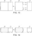
- An electrical connector 270 ( FIG. 13 ) for the blower unit 200 is connected to the electrical linkage plug 230 so that power to both units may be supplied by power supply 217.
- An air inlet 250 is disposed at the front of the pump unit 212 where the filter assembly 223 has been removed. The air inlet 250 engages with an outlet 275 in the blower unit 200.
- User interface 206 includes a control for selecting either the blower unit 200 or the pump unit 212 to convey the surgical smoke.
- FIGS. 13-14 show the conversion of the individual units into a single dual smoke evacuation system.
- the blower unit 200 may be provided with mechanical connectors 260, 263 for engaging with corresponding openings in the pump unit 212.
- the electrical connector 270 engages with the electrical linkage plug 230.
- the air outlet 275 engages with the air inlet 250 on the pump unit 212.
Landscapes
- Health & Medical Sciences (AREA)
- Surgery (AREA)
- Life Sciences & Earth Sciences (AREA)
- Engineering & Computer Science (AREA)
- General Health & Medical Sciences (AREA)
- Public Health (AREA)
- Veterinary Medicine (AREA)
- Biomedical Technology (AREA)
- Heart & Thoracic Surgery (AREA)
- Medical Informatics (AREA)
- Molecular Biology (AREA)
- Animal Behavior & Ethology (AREA)
- Nuclear Medicine, Radiotherapy & Molecular Imaging (AREA)
- Chemical & Material Sciences (AREA)
- Pathology (AREA)
- Oral & Maxillofacial Surgery (AREA)
- Combustion & Propulsion (AREA)
- Mechanical Engineering (AREA)
- General Engineering & Computer Science (AREA)
- Chemical Kinetics & Catalysis (AREA)
- Otolaryngology (AREA)
- Respiratory Apparatuses And Protective Means (AREA)
- Structures Of Non-Positive Displacement Pumps (AREA)
- Surgical Instruments (AREA)
Claims (6)
- Vorrichtung zur Evakuierung, die Folgendes umfasst(a) ein Gebläse (200) mit einem Gehäuse, das einen Gebläsemotor (202), eine Benutzerschnittstelle (206), eine Öffnung, eine Gebläsestromversorgung (203), einen Filter (209), einen elektrischen Verbinder (270) und ein einstellbares Element aufnimmt,wobei der Gebläsemotor (202) betreibbar ist, um ein Fluid durch die Öffnung und das einstellbare Element zu drücken,wobei der Filter (209) betreibbar ist, um Fremdmaterialien aus der Flüssigkeit zu filtern, die durch die Öffnung und das einstellbare Element fließt,wobei das einstellbare Element betätigt werden kann, um die Größe der Öffnung auf mehrere verschiedene Durchmesser zu ändern, undwobei die Benutzerschnittstelle (206) betreibbar ist, um den Gebläsemotor (202) zu steuern; und(b) eine Pumpe (212) mit einem Gehäuse, das einen Pumpenmotor (214), eine Pumpenbenutzerschnittstelle (220), einen Pumpenanschluss, eine Pumpenstromversorgung (217), ein elektrisches Gestänge (230) und einen entfernbaren Pumpenfilter (223) aufnimmt,wobei der Pumpenmotor (214) betreibbar ist, um ein Fluid durch die Pumpenöffnung zu drücken,wobei der Pumpenfilter (223) betreibbar ist, um Fremdmaterialien aus der Flüssigkeit zu filtern, die durch den Pumpenanschluss fließen;wobei der elektrische Verbinder (270) und das elektrische Gestänge (230) so betrieben werden können, dass sie miteinander gekoppelt werden können, wodurch das Gebläse (200) und die Pumpe (212) miteinander verbunden werden; undwobei die Benutzerschnittstelle (206) betreibbar ist, um den Gebläsemotor (202) und den Pumpenmotor (214) zu steuern, wenn der elektrische Verbinder (270) und das elektrische Gestänge (230) miteinander gekoppelt sind.
- Vorrichtung nach Anspruch 1, wobei der elektrische Verbinder (270) und das elektrische Gestänge (230) dazu dienen, das Gebläse (200) und die Pumpe (212) mechanisch und elektrisch zu verbinden.
- Vorrichtung nach Anspruch 1, wobei die Benutzerschnittstelle (206) eine Steuerung umfasst, die betätigt werden kann, um entweder das Gebläse (200) oder die Pumpe (212) zur Förderung des Fluids auszuwählen.
- Vorrichtung nach Anspruch 1, wobei die Gebläsestromversorgung (203) so betrieben werden kann, dass sie das Gebläse (200) und die Pumpe (212) über den elektrischen Verbinder (270) und das elektrische Gestänge (230) mit Strom versorgt.
- Vorrichtung nach Anspruch 1, wobei der Filter (209) betreibbar ist, um Fremdmaterialien aus einem Fluid, das durch die Öffnung strömt, und einem Fluid, das durch den Pumpenanschluss strömt, zu filtern, wenn der elektrische Verbinder (270) und das elektrische Gestänge (230) miteinander verbunden sind.
- Vorrichtung nach einem der Ansprüche 1 bis 5, wobei das Gebläse (200) und die Pumpe (212) so betrieben werden können, dass sie eine Flüssigkeit von einer chirurgischen Stelle absaugen.
Applications Claiming Priority (3)
| Application Number | Priority Date | Filing Date | Title |
|---|---|---|---|
| US201562267123P | 2015-12-14 | 2015-12-14 | |
| PCT/US2016/066678 WO2017106360A1 (en) | 2015-12-14 | 2016-12-14 | Method and apparatus for attachment and evacuation |
| EP16876602.0A EP3389525B1 (de) | 2015-12-14 | 2016-12-14 | Verfahren und vorrichtung zur befestigung und evakuierung |
Related Parent Applications (2)
| Application Number | Title | Priority Date | Filing Date |
|---|---|---|---|
| EP16876602.0A Division EP3389525B1 (de) | 2015-12-14 | 2016-12-14 | Verfahren und vorrichtung zur befestigung und evakuierung |
| EP16876602.0A Division-Into EP3389525B1 (de) | 2015-12-14 | 2016-12-14 | Verfahren und vorrichtung zur befestigung und evakuierung |
Publications (2)
| Publication Number | Publication Date |
|---|---|
| EP3964149A1 EP3964149A1 (de) | 2022-03-09 |
| EP3964149B1 true EP3964149B1 (de) | 2025-01-01 |
Family
ID=59019043
Family Applications (2)
| Application Number | Title | Priority Date | Filing Date |
|---|---|---|---|
| EP21202994.6A Active EP3964149B1 (de) | 2015-12-14 | 2016-12-14 | Vorrichtung zur befestigung und evakuierung |
| EP16876602.0A Active EP3389525B1 (de) | 2015-12-14 | 2016-12-14 | Verfahren und vorrichtung zur befestigung und evakuierung |
Family Applications After (1)
| Application Number | Title | Priority Date | Filing Date |
|---|---|---|---|
| EP16876602.0A Active EP3389525B1 (de) | 2015-12-14 | 2016-12-14 | Verfahren und vorrichtung zur befestigung und evakuierung |
Country Status (6)
| Country | Link |
|---|---|
| US (2) | US10751768B2 (de) |
| EP (2) | EP3964149B1 (de) |
| AU (3) | AU2016370636B2 (de) |
| CA (2) | CA3005094C (de) |
| ES (2) | ES3014388T3 (de) |
| WO (1) | WO2017106360A1 (de) |
Families Citing this family (143)
| Publication number | Priority date | Publication date | Assignee | Title |
|---|---|---|---|---|
| US11871901B2 (en) | 2012-05-20 | 2024-01-16 | Cilag Gmbh International | Method for situational awareness for surgical network or surgical network connected device capable of adjusting function based on a sensed situation or usage |
| US11504192B2 (en) | 2014-10-30 | 2022-11-22 | Cilag Gmbh International | Method of hub communication with surgical instrument systems |
| US10682129B2 (en) * | 2017-03-23 | 2020-06-16 | Mobius Imaging, Llc | Robotic end effector with adjustable inner diameter |
| US11229436B2 (en) | 2017-10-30 | 2022-01-25 | Cilag Gmbh International | Surgical system comprising a surgical tool and a surgical hub |
| US11311342B2 (en) | 2017-10-30 | 2022-04-26 | Cilag Gmbh International | Method for communicating with surgical instrument systems |
| US11317919B2 (en) | 2017-10-30 | 2022-05-03 | Cilag Gmbh International | Clip applier comprising a clip crimping system |
| US11564756B2 (en) | 2017-10-30 | 2023-01-31 | Cilag Gmbh International | Method of hub communication with surgical instrument systems |
| US11911045B2 (en) | 2017-10-30 | 2024-02-27 | Cllag GmbH International | Method for operating a powered articulating multi-clip applier |
| US11291510B2 (en) | 2017-10-30 | 2022-04-05 | Cilag Gmbh International | Method of hub communication with surgical instrument systems |
| US11801098B2 (en) | 2017-10-30 | 2023-10-31 | Cilag Gmbh International | Method of hub communication with surgical instrument systems |
| US11510741B2 (en) | 2017-10-30 | 2022-11-29 | Cilag Gmbh International | Method for producing a surgical instrument comprising a smart electrical system |
| US11051836B2 (en) | 2017-10-30 | 2021-07-06 | Cilag Gmbh International | Surgical clip applier comprising an empty clip cartridge lockout |
| US11141160B2 (en) | 2017-10-30 | 2021-10-12 | Cilag Gmbh International | Clip applier comprising a motor controller |
| USD912762S1 (en) | 2017-11-29 | 2021-03-09 | Megadyne Medical Products, Inc. | Fluid trap |
| US11234754B2 (en) | 2017-11-29 | 2022-02-01 | Megadyne Medical Products, Inc. | Smoke evacuation device |
| US10758855B2 (en) | 2017-11-29 | 2020-09-01 | Megadyne Medical Products, Inc. | Smoke evacuation system fluid trap |
| US10631916B2 (en) | 2017-11-29 | 2020-04-28 | Megadyne Medical Products, Inc. | Filter connection for a smoke evacuation device |
| USD868236S1 (en) | 2017-11-29 | 2019-11-26 | Megadyne Medical Products, Inc. | Smoke evacuation device control panel |
| USD886976S1 (en) | 2017-11-29 | 2020-06-09 | Megadyne Medical Products, Inc. | Filter cartridge |
| USD868287S1 (en) | 2017-11-29 | 2019-11-26 | Megadyne Medical Products, Inc. | Remote activation clip |
| US11389225B2 (en) | 2017-11-29 | 2022-07-19 | Megadyne Medical Products, Inc. | Smoke evacuation device remote activation system |
| US11725664B2 (en) | 2017-11-29 | 2023-08-15 | Megadyne Medical Products, Inc. | Noise and vibration management for smoke evacuation system |
| US10758856B2 (en) | 2017-11-29 | 2020-09-01 | Megadyne Medical Products, Inc. | Filter medium compression system for smoke evacuation |
| US10758293B2 (en) | 2017-11-29 | 2020-09-01 | Megadyne Medical Products, Inc. | Smoke evacuation device inlet and outlet manifolds |
| US11257589B2 (en) | 2017-12-28 | 2022-02-22 | Cilag Gmbh International | Real-time analysis of comprehensive cost of all instrumentation used in surgery utilizing data fluidity to track instruments through stocking and in-house processes |
| US20190201090A1 (en) | 2017-12-28 | 2019-07-04 | Ethicon Llc | Capacitive coupled return path pad with separable array elements |
| US11410259B2 (en) | 2017-12-28 | 2022-08-09 | Cilag Gmbh International | Adaptive control program updates for surgical devices |
| US11076921B2 (en) | 2017-12-28 | 2021-08-03 | Cilag Gmbh International | Adaptive control program updates for surgical hubs |
| US11571234B2 (en) | 2017-12-28 | 2023-02-07 | Cilag Gmbh International | Temperature control of ultrasonic end effector and control system therefor |
| US11424027B2 (en) | 2017-12-28 | 2022-08-23 | Cilag Gmbh International | Method for operating surgical instrument systems |
| US11132462B2 (en) | 2017-12-28 | 2021-09-28 | Cilag Gmbh International | Data stripping method to interrogate patient records and create anonymized record |
| US11056244B2 (en) | 2017-12-28 | 2021-07-06 | Cilag Gmbh International | Automated data scaling, alignment, and organizing based on predefined parameters within surgical networks |
| US11540855B2 (en) | 2017-12-28 | 2023-01-03 | Cilag Gmbh International | Controlling activation of an ultrasonic surgical instrument according to the presence of tissue |
| US11464559B2 (en) | 2017-12-28 | 2022-10-11 | Cilag Gmbh International | Estimating state of ultrasonic end effector and control system therefor |
| US11864728B2 (en) | 2017-12-28 | 2024-01-09 | Cilag Gmbh International | Characterization of tissue irregularities through the use of mono-chromatic light refractivity |
| US10932872B2 (en) | 2017-12-28 | 2021-03-02 | Ethicon Llc | Cloud-based medical analytics for linking of local usage trends with the resource acquisition behaviors of larger data set |
| US11612444B2 (en) | 2017-12-28 | 2023-03-28 | Cilag Gmbh International | Adjustment of a surgical device function based on situational awareness |
| US11051876B2 (en) * | 2017-12-28 | 2021-07-06 | Cilag Gmbh International | Surgical evacuation flow paths |
| US11832840B2 (en) | 2017-12-28 | 2023-12-05 | Cilag Gmbh International | Surgical instrument having a flexible circuit |
| US20190201112A1 (en) | 2017-12-28 | 2019-07-04 | Ethicon Llc | Computer implemented interactive surgical systems |
| US11678881B2 (en) | 2017-12-28 | 2023-06-20 | Cilag Gmbh International | Spatial awareness of surgical hubs in operating rooms |
| US11432885B2 (en) | 2017-12-28 | 2022-09-06 | Cilag Gmbh International | Sensing arrangements for robot-assisted surgical platforms |
| US11969216B2 (en) | 2017-12-28 | 2024-04-30 | Cilag Gmbh International | Surgical network recommendations from real time analysis of procedure variables against a baseline highlighting differences from the optimal solution |
| US11096693B2 (en) | 2017-12-28 | 2021-08-24 | Cilag Gmbh International | Adjustment of staple height of at least one row of staples based on the sensed tissue thickness or force in closing |
| US10944728B2 (en) | 2017-12-28 | 2021-03-09 | Ethicon Llc | Interactive surgical systems with encrypted communication capabilities |
| US11419667B2 (en) | 2017-12-28 | 2022-08-23 | Cilag Gmbh International | Ultrasonic energy device which varies pressure applied by clamp arm to provide threshold control pressure at a cut progression location |
| US11576677B2 (en) | 2017-12-28 | 2023-02-14 | Cilag Gmbh International | Method of hub communication, processing, display, and cloud analytics |
| US11179175B2 (en) | 2017-12-28 | 2021-11-23 | Cilag Gmbh International | Controlling an ultrasonic surgical instrument according to tissue location |
| US11602393B2 (en) | 2017-12-28 | 2023-03-14 | Cilag Gmbh International | Surgical evacuation sensing and generator control |
| US11529187B2 (en) | 2017-12-28 | 2022-12-20 | Cilag Gmbh International | Surgical evacuation sensor arrangements |
| US11832899B2 (en) | 2017-12-28 | 2023-12-05 | Cilag Gmbh International | Surgical systems with autonomously adjustable control programs |
| US12376855B2 (en) | 2017-12-28 | 2025-08-05 | Cilag Gmbh International | Safety systems for smart powered surgical stapling |
| US11559308B2 (en) | 2017-12-28 | 2023-01-24 | Cilag Gmbh International | Method for smart energy device infrastructure |
| US11324557B2 (en) | 2017-12-28 | 2022-05-10 | Cilag Gmbh International | Surgical instrument with a sensing array |
| US11744604B2 (en) | 2017-12-28 | 2023-09-05 | Cilag Gmbh International | Surgical instrument with a hardware-only control circuit |
| US11818052B2 (en) | 2017-12-28 | 2023-11-14 | Cilag Gmbh International | Surgical network determination of prioritization of communication, interaction, or processing based on system or device needs |
| US11857152B2 (en) | 2017-12-28 | 2024-01-02 | Cilag Gmbh International | Surgical hub spatial awareness to determine devices in operating theater |
| US20190201087A1 (en) | 2017-12-28 | 2019-07-04 | Ethicon Llc | Smoke evacuation system including a segmented control circuit for interactive surgical platform |
| US11109866B2 (en) | 2017-12-28 | 2021-09-07 | Cilag Gmbh International | Method for circular stapler control algorithm adjustment based on situational awareness |
| US12096916B2 (en) | 2017-12-28 | 2024-09-24 | Cilag Gmbh International | Method of sensing particulate from smoke evacuated from a patient, adjusting the pump speed based on the sensed information, and communicating the functional parameters of the system to the hub |
| US10595887B2 (en) | 2017-12-28 | 2020-03-24 | Ethicon Llc | Systems for adjusting end effector parameters based on perioperative information |
| US11589888B2 (en) | 2017-12-28 | 2023-02-28 | Cilag Gmbh International | Method for controlling smart energy devices |
| US11284936B2 (en) | 2017-12-28 | 2022-03-29 | Cilag Gmbh International | Surgical instrument having a flexible electrode |
| US11308075B2 (en) | 2017-12-28 | 2022-04-19 | Cilag Gmbh International | Surgical network, instrument, and cloud responses based on validation of received dataset and authentication of its source and integrity |
| US11633237B2 (en) | 2017-12-28 | 2023-04-25 | Cilag Gmbh International | Usage and technique analysis of surgeon / staff performance against a baseline to optimize device utilization and performance for both current and future procedures |
| US11311306B2 (en) | 2017-12-28 | 2022-04-26 | Cilag Gmbh International | Surgical systems for detecting end effector tissue distribution irregularities |
| US11213359B2 (en) | 2017-12-28 | 2022-01-04 | Cilag Gmbh International | Controllers for robot-assisted surgical platforms |
| WO2019133144A1 (en) | 2017-12-28 | 2019-07-04 | Ethicon Llc | Detection and escalation of security responses of surgical instruments to increasing severity threats |
| US11069012B2 (en) | 2017-12-28 | 2021-07-20 | Cilag Gmbh International | Interactive surgical systems with condition handling of devices and data capabilities |
| US11234756B2 (en) | 2017-12-28 | 2022-02-01 | Cilag Gmbh International | Powered surgical tool with predefined adjustable control algorithm for controlling end effector parameter |
| US11364075B2 (en) | 2017-12-28 | 2022-06-21 | Cilag Gmbh International | Radio frequency energy device for delivering combined electrical signals |
| US11304720B2 (en) | 2017-12-28 | 2022-04-19 | Cilag Gmbh International | Activation of energy devices |
| US11998193B2 (en) | 2017-12-28 | 2024-06-04 | Cilag Gmbh International | Method for usage of the shroud as an aspect of sensing or controlling a powered surgical device, and a control algorithm to adjust its default operation |
| US11786245B2 (en) | 2017-12-28 | 2023-10-17 | Cilag Gmbh International | Surgical systems with prioritized data transmission capabilities |
| US11446052B2 (en) | 2017-12-28 | 2022-09-20 | Cilag Gmbh International | Variation of radio frequency and ultrasonic power level in cooperation with varying clamp arm pressure to achieve predefined heat flux or power applied to tissue |
| US11179208B2 (en) | 2017-12-28 | 2021-11-23 | Cilag Gmbh International | Cloud-based medical analytics for security and authentication trends and reactive measures |
| US11786251B2 (en) | 2017-12-28 | 2023-10-17 | Cilag Gmbh International | Method for adaptive control schemes for surgical network control and interaction |
| US11423007B2 (en) | 2017-12-28 | 2022-08-23 | Cilag Gmbh International | Adjustment of device control programs based on stratified contextual data in addition to the data |
| US11464535B2 (en) | 2017-12-28 | 2022-10-11 | Cilag Gmbh International | Detection of end effector emersion in liquid |
| JP2021509061A (ja) | 2017-12-28 | 2021-03-18 | エシコン エルエルシーEthicon LLC | 状況認識に基づく外科用デバイスの機能の調節 |
| US11389164B2 (en) | 2017-12-28 | 2022-07-19 | Cilag Gmbh International | Method of using reinforced flexible circuits with multiple sensors to optimize performance of radio frequency devices |
| US20190206569A1 (en) | 2017-12-28 | 2019-07-04 | Ethicon Llc | Method of cloud based data analytics for use with the hub |
| US11304745B2 (en) | 2017-12-28 | 2022-04-19 | Cilag Gmbh International | Surgical evacuation sensing and display |
| US11896443B2 (en) | 2017-12-28 | 2024-02-13 | Cilag Gmbh International | Control of a surgical system through a surgical barrier |
| US10966791B2 (en) | 2017-12-28 | 2021-04-06 | Ethicon Llc | Cloud-based medical analytics for medical facility segmented individualization of instrument function |
| US10892995B2 (en) | 2017-12-28 | 2021-01-12 | Ethicon Llc | Surgical network determination of prioritization of communication, interaction, or processing based on system or device needs |
| US11304763B2 (en) | 2017-12-28 | 2022-04-19 | Cilag Gmbh International | Image capturing of the areas outside the abdomen to improve placement and control of a surgical device in use |
| US11672605B2 (en) | 2017-12-28 | 2023-06-13 | Cilag Gmbh International | Sterile field interactive control displays |
| US11266468B2 (en) | 2017-12-28 | 2022-03-08 | Cilag Gmbh International | Cooperative utilization of data derived from secondary sources by intelligent surgical hubs |
| US10892899B2 (en) | 2017-12-28 | 2021-01-12 | Ethicon Llc | Self describing data packets generated at an issuing instrument |
| US20190201113A1 (en) | 2017-12-28 | 2019-07-04 | Ethicon Llc | Controls for robot-assisted surgical platforms |
| US11304699B2 (en) | 2017-12-28 | 2022-04-19 | Cilag Gmbh International | Method for adaptive control schemes for surgical network control and interaction |
| US12127729B2 (en) | 2017-12-28 | 2024-10-29 | Cilag Gmbh International | Method for smoke evacuation for surgical hub |
| US11903601B2 (en) | 2017-12-28 | 2024-02-20 | Cilag Gmbh International | Surgical instrument comprising a plurality of drive systems |
| US11666331B2 (en) | 2017-12-28 | 2023-06-06 | Cilag Gmbh International | Systems for detecting proximity of surgical end effector to cancerous tissue |
| US10918310B2 (en) | 2018-01-03 | 2021-02-16 | Biosense Webster (Israel) Ltd. | Fast anatomical mapping (FAM) using volume filling |
| US11659023B2 (en) | 2017-12-28 | 2023-05-23 | Cilag Gmbh International | Method of hub communication |
| US12458351B2 (en) | 2017-12-28 | 2025-11-04 | Cilag Gmbh International | Variable output cartridge sensor assembly |
| US11166772B2 (en) | 2017-12-28 | 2021-11-09 | Cilag Gmbh International | Surgical hub coordination of control and communication of operating room devices |
| US11100631B2 (en) | 2017-12-28 | 2021-08-24 | Cilag Gmbh International | Use of laser light and red-green-blue coloration to determine properties of back scattered light |
| US10943454B2 (en) | 2017-12-28 | 2021-03-09 | Ethicon Llc | Detection and escalation of security responses of surgical instruments to increasing severity threats |
| US11376002B2 (en) | 2017-12-28 | 2022-07-05 | Cilag Gmbh International | Surgical instrument cartridge sensor assemblies |
| US11419630B2 (en) | 2017-12-28 | 2022-08-23 | Cilag Gmbh International | Surgical system distributed processing |
| US12062442B2 (en) | 2017-12-28 | 2024-08-13 | Cilag Gmbh International | Method for operating surgical instrument systems |
| US10987178B2 (en) | 2017-12-28 | 2021-04-27 | Ethicon Llc | Surgical hub control arrangements |
| US11771487B2 (en) | 2017-12-28 | 2023-10-03 | Cilag Gmbh International | Mechanisms for controlling different electromechanical systems of an electrosurgical instrument |
| US11253315B2 (en) | 2017-12-28 | 2022-02-22 | Cilag Gmbh International | Increasing radio frequency to create pad-less monopolar loop |
| US12396806B2 (en) | 2017-12-28 | 2025-08-26 | Cilag Gmbh International | Adjustment of a surgical device function based on situational awareness |
| US11317937B2 (en) | 2018-03-08 | 2022-05-03 | Cilag Gmbh International | Determining the state of an ultrasonic end effector |
| US10758310B2 (en) | 2017-12-28 | 2020-09-01 | Ethicon Llc | Wireless pairing of a surgical device with another device within a sterile surgical field based on the usage and situational awareness of devices |
| US11278281B2 (en) | 2017-12-28 | 2022-03-22 | Cilag Gmbh International | Interactive surgical system |
| US11273001B2 (en) | 2017-12-28 | 2022-03-15 | Cilag Gmbh International | Surgical hub and modular device response adjustment based on situational awareness |
| US11937769B2 (en) | 2017-12-28 | 2024-03-26 | Cilag Gmbh International | Method of hub communication, processing, storage and display |
| US11160605B2 (en) | 2017-12-28 | 2021-11-02 | Cilag Gmbh International | Surgical evacuation sensing and motor control |
| US10898622B2 (en) | 2017-12-28 | 2021-01-26 | Ethicon Llc | Surgical evacuation system with a communication circuit for communication between a filter and a smoke evacuation device |
| US11559307B2 (en) | 2017-12-28 | 2023-01-24 | Cilag Gmbh International | Method of robotic hub communication, detection, and control |
| US11969142B2 (en) | 2017-12-28 | 2024-04-30 | Cilag Gmbh International | Method of compressing tissue within a stapling device and simultaneously displaying the location of the tissue within the jaws |
| US11202570B2 (en) | 2017-12-28 | 2021-12-21 | Cilag Gmbh International | Communication hub and storage device for storing parameters and status of a surgical device to be shared with cloud based analytics systems |
| US10849697B2 (en) | 2017-12-28 | 2020-12-01 | Ethicon Llc | Cloud interface for coupled surgical devices |
| US11291495B2 (en) | 2017-12-28 | 2022-04-05 | Cilag Gmbh International | Interruption of energy due to inadvertent capacitive coupling |
| US11896322B2 (en) | 2017-12-28 | 2024-02-13 | Cilag Gmbh International | Sensing the patient position and contact utilizing the mono-polar return pad electrode to provide situational awareness to the hub |
| US11147607B2 (en) | 2017-12-28 | 2021-10-19 | Cilag Gmbh International | Bipolar combination device that automatically adjusts pressure based on energy modality |
| US12303159B2 (en) | 2018-03-08 | 2025-05-20 | Cilag Gmbh International | Methods for estimating and controlling state of ultrasonic end effector |
| US11986233B2 (en) | 2018-03-08 | 2024-05-21 | Cilag Gmbh International | Adjustment of complex impedance to compensate for lost power in an articulating ultrasonic device |
| US11259830B2 (en) | 2018-03-08 | 2022-03-01 | Cilag Gmbh International | Methods for controlling temperature in ultrasonic device |
| US11399858B2 (en) | 2018-03-08 | 2022-08-02 | Cilag Gmbh International | Application of smart blade technology |
| US10973520B2 (en) | 2018-03-28 | 2021-04-13 | Ethicon Llc | Surgical staple cartridge with firing member driven camming assembly that has an onboard tissue cutting feature |
| US11471156B2 (en) | 2018-03-28 | 2022-10-18 | Cilag Gmbh International | Surgical stapling devices with improved rotary driven closure systems |
| US11278280B2 (en) | 2018-03-28 | 2022-03-22 | Cilag Gmbh International | Surgical instrument comprising a jaw closure lockout |
| US11129611B2 (en) | 2018-03-28 | 2021-09-28 | Cilag Gmbh International | Surgical staplers with arrangements for maintaining a firing member thereof in a locked configuration unless a compatible cartridge has been installed therein |
| US11207067B2 (en) | 2018-03-28 | 2021-12-28 | Cilag Gmbh International | Surgical stapling device with separate rotary driven closure and firing systems and firing member that engages both jaws while firing |
| US11259806B2 (en) | 2018-03-28 | 2022-03-01 | Cilag Gmbh International | Surgical stapling devices with features for blocking advancement of a camming assembly of an incompatible cartridge installed therein |
| US11219453B2 (en) | 2018-03-28 | 2022-01-11 | Cilag Gmbh International | Surgical stapling devices with cartridge compatible closure and firing lockout arrangements |
| US11090047B2 (en) | 2018-03-28 | 2021-08-17 | Cilag Gmbh International | Surgical instrument comprising an adaptive control system |
| US11096688B2 (en) | 2018-03-28 | 2021-08-24 | Cilag Gmbh International | Rotary driven firing members with different anvil and channel engagement features |
| US11357503B2 (en) | 2019-02-19 | 2022-06-14 | Cilag Gmbh International | Staple cartridge retainers with frangible retention features and methods of using same |
| US11317915B2 (en) | 2019-02-19 | 2022-05-03 | Cilag Gmbh International | Universal cartridge based key feature that unlocks multiple lockout arrangements in different surgical staplers |
| US11298130B2 (en) | 2019-02-19 | 2022-04-12 | Cilag Gmbh International | Staple cartridge retainer with frangible authentication key |
| US11464511B2 (en) | 2019-02-19 | 2022-10-11 | Cilag Gmbh International | Surgical staple cartridges with movable authentication key arrangements |
| US11369377B2 (en) | 2019-02-19 | 2022-06-28 | Cilag Gmbh International | Surgical stapling assembly with cartridge based retainer configured to unlock a firing lockout |
| USD964564S1 (en) | 2019-06-25 | 2022-09-20 | Cilag Gmbh International | Surgical staple cartridge retainer with a closure system authentication key |
| USD950728S1 (en) | 2019-06-25 | 2022-05-03 | Cilag Gmbh International | Surgical staple cartridge |
| USD952144S1 (en) | 2019-06-25 | 2022-05-17 | Cilag Gmbh International | Surgical staple cartridge retainer with firing system authentication key |
Family Cites Families (19)
| Publication number | Priority date | Publication date | Assignee | Title |
|---|---|---|---|---|
| US2064344A (en) * | 1933-08-25 | 1936-12-15 | Charles A Good | Combination blower and suction sweeper |
| US3321970A (en) * | 1964-10-15 | 1967-05-30 | Charles Wheatley Company | Dual orifice plug fitting |
| US4094492A (en) * | 1977-01-18 | 1978-06-13 | The United States Of America As Represented By The United States Department Of Energy | Variable orifice using an iris shutter |
| DE2806271A1 (de) * | 1978-02-15 | 1979-08-23 | Miele & Cie | Vorrichtung zum steuern der nebenluftzufuhr bei staubsaugern |
| US4986839A (en) | 1988-11-10 | 1991-01-22 | Surgical Laser Products, Inc. | Self-contained air enhancement and laser plume evacuation system |
| US5971977A (en) * | 1996-07-22 | 1999-10-26 | Korenfeld; Michael S. | Surgical laser smoke plume evacuator |
| US5968032A (en) * | 1998-03-30 | 1999-10-19 | Sleister; Dennis R. | Smoke evacuator for a surgical laser or cautery plume |
| US6001077A (en) * | 1998-05-26 | 1999-12-14 | Ellman; Alan G. | Vacuum wand for surgical smoke plume evacuation system |
| KR100367664B1 (ko) * | 2000-02-08 | 2003-01-24 | 주식회사 지인텍 | 휴대용 콧물 흡입기 |
| EP1351008A1 (de) * | 2002-03-21 | 2003-10-08 | JohnsonDiversey, Inc. | Durchflussbegrenzer |
| US6592543B1 (en) * | 2002-04-03 | 2003-07-15 | Surgin Inc. | Fluid flow regulator for a smoke evacuation system and method of using same |
| EP1677893A4 (de) | 2003-09-15 | 2009-01-07 | Medtek Devices Inc | Operationssaal-rauchabsauger mit integriertem vakuummotor und filter |
| US8167337B2 (en) * | 2003-12-19 | 2012-05-01 | Bruno Frank L | Elastic coupling for universal vacuum extension kit |
| JP2009519757A (ja) * | 2005-12-14 | 2009-05-21 | ストライカー・コーポレイション | 医療用/外科用廃棄物収集・処理システム |
| US8414521B2 (en) * | 2006-11-06 | 2013-04-09 | Aardvark Medical, Inc. | Irrigation and aspiration devices and methods |
| US20100305523A1 (en) * | 2009-05-27 | 2010-12-02 | Tyco Healthcare Group Lp | Active Exudate Control System |
| US20120109034A1 (en) * | 2010-10-27 | 2012-05-03 | Kci Licensing, Inc. | Interactive, wireless reduced-pressure dressings, methods, and systems |
| US9080704B2 (en) | 2011-07-29 | 2015-07-14 | Shaun M. Flanery | Universal pipe coupler |
| DE112014001842T5 (de) * | 2013-04-05 | 2015-12-31 | Nascent Surgical, Llc | Absaugsystem |
-
2016
- 2016-12-14 EP EP21202994.6A patent/EP3964149B1/de active Active
- 2016-12-14 CA CA3005094A patent/CA3005094C/en active Active
- 2016-12-14 AU AU2016370636A patent/AU2016370636B2/en active Active
- 2016-12-14 EP EP16876602.0A patent/EP3389525B1/de active Active
- 2016-12-14 CA CA3054026A patent/CA3054026C/en active Active
- 2016-12-14 ES ES21202994T patent/ES3014388T3/es active Active
- 2016-12-14 WO PCT/US2016/066678 patent/WO2017106360A1/en not_active Ceased
- 2016-12-14 US US15/379,175 patent/US10751768B2/en active Active
- 2016-12-14 ES ES16876602T patent/ES2906768T3/es active Active
-
2020
- 2020-07-15 US US16/929,915 patent/US12576433B2/en active Active
- 2020-10-27 AU AU2020260420A patent/AU2020260420A1/en not_active Abandoned
-
2022
- 2022-06-21 AU AU2022204356A patent/AU2022204356B2/en active Active
Also Published As
| Publication number | Publication date |
|---|---|
| EP3964149A1 (de) | 2022-03-09 |
| CA3054026A1 (en) | 2017-06-22 |
| WO2017106360A1 (en) | 2017-06-22 |
| CA3005094C (en) | 2021-05-25 |
| AU2022204356B2 (en) | 2024-08-29 |
| CA3005094A1 (en) | 2017-06-22 |
| CA3054026C (en) | 2022-01-25 |
| EP3389525A4 (de) | 2019-08-14 |
| AU2016370636B2 (en) | 2020-07-23 |
| AU2022204356A1 (en) | 2022-07-14 |
| US10751768B2 (en) | 2020-08-25 |
| ES3014388T3 (en) | 2025-04-22 |
| AU2020260420A1 (en) | 2020-11-26 |
| ES2906768T3 (es) | 2022-04-20 |
| EP3389525B1 (de) | 2022-02-02 |
| EP3389525A1 (de) | 2018-10-24 |
| US12576433B2 (en) | 2026-03-17 |
| AU2016370636A1 (en) | 2018-06-07 |
| US20210060626A1 (en) | 2021-03-04 |
| US20170165725A1 (en) | 2017-06-15 |
Similar Documents
| Publication | Publication Date | Title |
|---|---|---|
| EP3964149B1 (de) | Vorrichtung zur befestigung und evakuierung | |
| EP3435901B1 (de) | Rauchabzugssystem für invasive chirurgische eingriffe | |
| US20240099762A1 (en) | Electrosurgical device with vacuum port having multiple swivel connections | |
| US8784300B2 (en) | Devices, systems, and methods for removing empyema from a pleural cavity | |
| CA3093039C (en) | Method and apparatus for fluid evacuation during surgical procedures | |
| EP3740260B1 (de) | Vorrichtung für durchfluss |
Legal Events
| Date | Code | Title | Description |
|---|---|---|---|
| PUAI | Public reference made under article 153(3) epc to a published international application that has entered the european phase |
Free format text: ORIGINAL CODE: 0009012 |
|
| STAA | Information on the status of an ep patent application or granted ep patent |
Free format text: STATUS: THE APPLICATION HAS BEEN PUBLISHED |
|
| AC | Divisional application: reference to earlier application |
Ref document number: 3389525 Country of ref document: EP Kind code of ref document: P |
|
| AK | Designated contracting states |
Kind code of ref document: A1 Designated state(s): AL AT BE BG CH CY CZ DE DK EE ES FI FR GB GR HR HU IE IS IT LI LT LU LV MC MK MT NL NO PL PT RO RS SE SI SK SM TR |
|
| STAA | Information on the status of an ep patent application or granted ep patent |
Free format text: STATUS: REQUEST FOR EXAMINATION WAS MADE |
|
| 17P | Request for examination filed |
Effective date: 20220908 |
|
| RBV | Designated contracting states (corrected) |
Designated state(s): AL AT BE BG CH CY CZ DE DK EE ES FI FR GB GR HR HU IE IS IT LI LT LU LV MC MK MT NL NO PL PT RO RS SE SI SK SM TR |
|
| P01 | Opt-out of the competence of the unified patent court (upc) registered |
Effective date: 20230529 |
|
| GRAP | Despatch of communication of intention to grant a patent |
Free format text: ORIGINAL CODE: EPIDOSNIGR1 |
|
| STAA | Information on the status of an ep patent application or granted ep patent |
Free format text: STATUS: GRANT OF PATENT IS INTENDED |
|
| RIC1 | Information provided on ipc code assigned before grant |
Ipc: A61B 90/00 20160101ALI20240709BHEP Ipc: B01D 53/00 20060101ALI20240709BHEP Ipc: A61B 18/00 20060101AFI20240709BHEP |
|
| INTG | Intention to grant announced |
Effective date: 20240725 |
|
| GRAS | Grant fee paid |
Free format text: ORIGINAL CODE: EPIDOSNIGR3 |
|
| GRAA | (expected) grant |
Free format text: ORIGINAL CODE: 0009210 |
|
| STAA | Information on the status of an ep patent application or granted ep patent |
Free format text: STATUS: THE PATENT HAS BEEN GRANTED |
|
| AC | Divisional application: reference to earlier application |
Ref document number: 3389525 Country of ref document: EP Kind code of ref document: P |
|
| AK | Designated contracting states |
Kind code of ref document: B1 Designated state(s): AL AT BE BG CH CY CZ DE DK EE ES FI FR GB GR HR HU IE IS IT LI LT LU LV MC MK MT NL NO PL PT RO RS SE SI SK SM TR |
|
| REG | Reference to a national code |
Ref country code: GB Ref legal event code: FG4D |
|
| REG | Reference to a national code |
Ref country code: CH Ref legal event code: EP |
|
| REG | Reference to a national code |
Ref country code: DE Ref legal event code: R096 Ref document number: 602016090866 Country of ref document: DE |
|
| REG | Reference to a national code |
Ref country code: IE Ref legal event code: FG4D |
|
| REG | Reference to a national code |
Ref country code: ES Ref legal event code: FG2A Ref document number: 3014388 Country of ref document: ES Kind code of ref document: T3 Effective date: 20250422 |
|
| REG | Reference to a national code |
Ref country code: LT Ref legal event code: MG9D |
|
| REG | Reference to a national code |
Ref country code: NL Ref legal event code: MP Effective date: 20250101 |
|
| REG | Reference to a national code |
Ref country code: AT Ref legal event code: MK05 Ref document number: 1755467 Country of ref document: AT Kind code of ref document: T Effective date: 20250101 |
|
| PG25 | Lapsed in a contracting state [announced via postgrant information from national office to epo] |
Ref country code: NL Free format text: LAPSE BECAUSE OF FAILURE TO SUBMIT A TRANSLATION OF THE DESCRIPTION OR TO PAY THE FEE WITHIN THE PRESCRIBED TIME-LIMIT Effective date: 20250101 |
|
| PG25 | Lapsed in a contracting state [announced via postgrant information from national office to epo] |
Ref country code: FI Free format text: LAPSE BECAUSE OF FAILURE TO SUBMIT A TRANSLATION OF THE DESCRIPTION OR TO PAY THE FEE WITHIN THE PRESCRIBED TIME-LIMIT Effective date: 20250101 |
|
| PG25 | Lapsed in a contracting state [announced via postgrant information from national office to epo] |
Ref country code: PL Free format text: LAPSE BECAUSE OF FAILURE TO SUBMIT A TRANSLATION OF THE DESCRIPTION OR TO PAY THE FEE WITHIN THE PRESCRIBED TIME-LIMIT Effective date: 20250101 |
|
| PG25 | Lapsed in a contracting state [announced via postgrant information from national office to epo] |
Ref country code: NO Free format text: LAPSE BECAUSE OF FAILURE TO SUBMIT A TRANSLATION OF THE DESCRIPTION OR TO PAY THE FEE WITHIN THE PRESCRIBED TIME-LIMIT Effective date: 20250401 Ref country code: IS Free format text: LAPSE BECAUSE OF FAILURE TO SUBMIT A TRANSLATION OF THE DESCRIPTION OR TO PAY THE FEE WITHIN THE PRESCRIBED TIME-LIMIT Effective date: 20250501 |
|
| PG25 | Lapsed in a contracting state [announced via postgrant information from national office to epo] |
Ref country code: HR Free format text: LAPSE BECAUSE OF FAILURE TO SUBMIT A TRANSLATION OF THE DESCRIPTION OR TO PAY THE FEE WITHIN THE PRESCRIBED TIME-LIMIT Effective date: 20250101 |
|
| PG25 | Lapsed in a contracting state [announced via postgrant information from national office to epo] |
Ref country code: LV Free format text: LAPSE BECAUSE OF FAILURE TO SUBMIT A TRANSLATION OF THE DESCRIPTION OR TO PAY THE FEE WITHIN THE PRESCRIBED TIME-LIMIT Effective date: 20250101 Ref country code: PT Free format text: LAPSE BECAUSE OF FAILURE TO SUBMIT A TRANSLATION OF THE DESCRIPTION OR TO PAY THE FEE WITHIN THE PRESCRIBED TIME-LIMIT Effective date: 20250502 |
|
| PG25 | Lapsed in a contracting state [announced via postgrant information from national office to epo] |
Ref country code: GR Free format text: LAPSE BECAUSE OF FAILURE TO SUBMIT A TRANSLATION OF THE DESCRIPTION OR TO PAY THE FEE WITHIN THE PRESCRIBED TIME-LIMIT Effective date: 20250402 Ref country code: BG Free format text: LAPSE BECAUSE OF FAILURE TO SUBMIT A TRANSLATION OF THE DESCRIPTION OR TO PAY THE FEE WITHIN THE PRESCRIBED TIME-LIMIT Effective date: 20250101 |
|
| PG25 | Lapsed in a contracting state [announced via postgrant information from national office to epo] |
Ref country code: AT Free format text: LAPSE BECAUSE OF FAILURE TO SUBMIT A TRANSLATION OF THE DESCRIPTION OR TO PAY THE FEE WITHIN THE PRESCRIBED TIME-LIMIT Effective date: 20250101 |
|
| PG25 | Lapsed in a contracting state [announced via postgrant information from national office to epo] |
Ref country code: CZ Free format text: LAPSE BECAUSE OF FAILURE TO SUBMIT A TRANSLATION OF THE DESCRIPTION OR TO PAY THE FEE WITHIN THE PRESCRIBED TIME-LIMIT Effective date: 20250101 |
|
| PG25 | Lapsed in a contracting state [announced via postgrant information from national office to epo] |
Ref country code: SE Free format text: LAPSE BECAUSE OF FAILURE TO SUBMIT A TRANSLATION OF THE DESCRIPTION OR TO PAY THE FEE WITHIN THE PRESCRIBED TIME-LIMIT Effective date: 20250101 |
|
| REG | Reference to a national code |
Ref country code: DE Ref legal event code: R097 Ref document number: 602016090866 Country of ref document: DE |
|
| PG25 | Lapsed in a contracting state [announced via postgrant information from national office to epo] |
Ref country code: SM Free format text: LAPSE BECAUSE OF FAILURE TO SUBMIT A TRANSLATION OF THE DESCRIPTION OR TO PAY THE FEE WITHIN THE PRESCRIBED TIME-LIMIT Effective date: 20250101 |
|
| PG25 | Lapsed in a contracting state [announced via postgrant information from national office to epo] |
Ref country code: DK Free format text: LAPSE BECAUSE OF FAILURE TO SUBMIT A TRANSLATION OF THE DESCRIPTION OR TO PAY THE FEE WITHIN THE PRESCRIBED TIME-LIMIT Effective date: 20250101 |
|
| PG25 | Lapsed in a contracting state [announced via postgrant information from national office to epo] |
Ref country code: EE Free format text: LAPSE BECAUSE OF FAILURE TO SUBMIT A TRANSLATION OF THE DESCRIPTION OR TO PAY THE FEE WITHIN THE PRESCRIBED TIME-LIMIT Effective date: 20250101 |
|
| PG25 | Lapsed in a contracting state [announced via postgrant information from national office to epo] |
Ref country code: RO Free format text: LAPSE BECAUSE OF FAILURE TO SUBMIT A TRANSLATION OF THE DESCRIPTION OR TO PAY THE FEE WITHIN THE PRESCRIBED TIME-LIMIT Effective date: 20250101 |
|
| PG25 | Lapsed in a contracting state [announced via postgrant information from national office to epo] |
Ref country code: SK Free format text: LAPSE BECAUSE OF FAILURE TO SUBMIT A TRANSLATION OF THE DESCRIPTION OR TO PAY THE FEE WITHIN THE PRESCRIBED TIME-LIMIT Effective date: 20250101 |
|
| PLBE | No opposition filed within time limit |
Free format text: ORIGINAL CODE: 0009261 |
|
| STAA | Information on the status of an ep patent application or granted ep patent |
Free format text: STATUS: NO OPPOSITION FILED WITHIN TIME LIMIT |
|
| 26N | No opposition filed |
Effective date: 20251002 |
|
| PGFP | Annual fee paid to national office [announced via postgrant information from national office to epo] |
Ref country code: DE Payment date: 20251126 Year of fee payment: 10 |
|
| PGFP | Annual fee paid to national office [announced via postgrant information from national office to epo] |
Ref country code: GB Payment date: 20251120 Year of fee payment: 10 |
|
| PGFP | Annual fee paid to national office [announced via postgrant information from national office to epo] |
Ref country code: IT Payment date: 20251126 Year of fee payment: 10 |
|
| PGFP | Annual fee paid to national office [announced via postgrant information from national office to epo] |
Ref country code: FR Payment date: 20251124 Year of fee payment: 10 |
|
| PGFP | Annual fee paid to national office [announced via postgrant information from national office to epo] |
Ref country code: ES Payment date: 20260115 Year of fee payment: 10 |