EP3964298B1 - Dispositif d'application d'un produit, machine comprenant un tel dispositif et procédé de contrôle d'une telle machine - Google Patents
Dispositif d'application d'un produit, machine comprenant un tel dispositif et procédé de contrôle d'une telle machine Download PDFInfo
- Publication number
- EP3964298B1 EP3964298B1 EP21195100.9A EP21195100A EP3964298B1 EP 3964298 B1 EP3964298 B1 EP 3964298B1 EP 21195100 A EP21195100 A EP 21195100A EP 3964298 B1 EP3964298 B1 EP 3964298B1
- Authority
- EP
- European Patent Office
- Prior art keywords
- needle
- stop
- application device
- frame
- fixed
- Prior art date
- Legal status (The legal status is an assumption and is not a legal conclusion. Google has not performed a legal analysis and makes no representation as to the accuracy of the status listed.)
- Active
Links
Images



Classifications
-
- B—PERFORMING OPERATIONS; TRANSPORTING
- B05—SPRAYING OR ATOMISING IN GENERAL; APPLYING FLUENT MATERIALS TO SURFACES, IN GENERAL
- B05B—SPRAYING APPARATUS; ATOMISING APPARATUS; NOZZLES
- B05B12/00—Arrangements for controlling delivery; Arrangements for controlling the spray area
- B05B12/08—Arrangements for controlling delivery; Arrangements for controlling the spray area responsive to condition of liquid or other fluent material to be discharged, of ambient medium or of target ; responsive to condition of spray devices or of supply means, e.g. pipes, pumps or their drive means
- B05B12/085—Arrangements for controlling delivery; Arrangements for controlling the spray area responsive to condition of liquid or other fluent material to be discharged, of ambient medium or of target ; responsive to condition of spray devices or of supply means, e.g. pipes, pumps or their drive means responsive to flow or pressure of liquid or other fluent material to be discharged
-
- B—PERFORMING OPERATIONS; TRANSPORTING
- B05—SPRAYING OR ATOMISING IN GENERAL; APPLYING FLUENT MATERIALS TO SURFACES, IN GENERAL
- B05C—APPARATUS FOR APPLYING FLUENT MATERIALS TO SURFACES, IN GENERAL
- B05C5/00—Apparatus in which liquid or other fluent material is projected, poured or allowed to flow on to the surface of the work
- B05C5/02—Apparatus in which liquid or other fluent material is projected, poured or allowed to flow on to the surface of the work the liquid or other fluent material being discharged through an outlet orifice by pressure, e.g. from an outlet device in contact or almost in contact, with the work
- B05C5/0225—Apparatus in which liquid or other fluent material is projected, poured or allowed to flow on to the surface of the work the liquid or other fluent material being discharged through an outlet orifice by pressure, e.g. from an outlet device in contact or almost in contact, with the work characterised by flow controlling means, e.g. valves, located proximate the outlet
-
- B—PERFORMING OPERATIONS; TRANSPORTING
- B05—SPRAYING OR ATOMISING IN GENERAL; APPLYING FLUENT MATERIALS TO SURFACES, IN GENERAL
- B05C—APPARATUS FOR APPLYING FLUENT MATERIALS TO SURFACES, IN GENERAL
- B05C5/00—Apparatus in which liquid or other fluent material is projected, poured or allowed to flow on to the surface of the work
- B05C5/02—Apparatus in which liquid or other fluent material is projected, poured or allowed to flow on to the surface of the work the liquid or other fluent material being discharged through an outlet orifice by pressure, e.g. from an outlet device in contact or almost in contact, with the work
- B05C5/0208—Apparatus in which liquid or other fluent material is projected, poured or allowed to flow on to the surface of the work the liquid or other fluent material being discharged through an outlet orifice by pressure, e.g. from an outlet device in contact or almost in contact, with the work for applying liquid or other fluent material to separate articles
- B05C5/0212—Apparatus in which liquid or other fluent material is projected, poured or allowed to flow on to the surface of the work the liquid or other fluent material being discharged through an outlet orifice by pressure, e.g. from an outlet device in contact or almost in contact, with the work for applying liquid or other fluent material to separate articles only at particular parts of the articles
-
- B—PERFORMING OPERATIONS; TRANSPORTING
- B05—SPRAYING OR ATOMISING IN GENERAL; APPLYING FLUENT MATERIALS TO SURFACES, IN GENERAL
- B05C—APPARATUS FOR APPLYING FLUENT MATERIALS TO SURFACES, IN GENERAL
- B05C11/00—Component parts, details or accessories not specifically provided for in groups B05C1/00 - B05C9/00
-
- B—PERFORMING OPERATIONS; TRANSPORTING
- B05—SPRAYING OR ATOMISING IN GENERAL; APPLYING FLUENT MATERIALS TO SURFACES, IN GENERAL
- B05C—APPARATUS FOR APPLYING FLUENT MATERIALS TO SURFACES, IN GENERAL
- B05C11/00—Component parts, details or accessories not specifically provided for in groups B05C1/00 - B05C9/00
- B05C11/10—Storage, supply or control of liquid or other fluent material; Recovery of excess liquid or other fluent material
- B05C11/1002—Means for controlling supply, i.e. flow or pressure, of liquid or other fluent material to the applying apparatus, e.g. valves
- B05C11/1026—Valves
- B05C11/1028—Lift valves
-
- B—PERFORMING OPERATIONS; TRANSPORTING
- B05—SPRAYING OR ATOMISING IN GENERAL; APPLYING FLUENT MATERIALS TO SURFACES, IN GENERAL
- B05C—APPARATUS FOR APPLYING FLUENT MATERIALS TO SURFACES, IN GENERAL
- B05C11/00—Component parts, details or accessories not specifically provided for in groups B05C1/00 - B05C9/00
- B05C11/10—Storage, supply or control of liquid or other fluent material; Recovery of excess liquid or other fluent material
- B05C11/1002—Means for controlling supply, i.e. flow or pressure, of liquid or other fluent material to the applying apparatus, e.g. valves
- B05C11/1034—Means for controlling supply, i.e. flow or pressure, of liquid or other fluent material to the applying apparatus, e.g. valves specially designed for conducting intermittent application of small quantities, e.g. drops, of coating material
-
- B—PERFORMING OPERATIONS; TRANSPORTING
- B05—SPRAYING OR ATOMISING IN GENERAL; APPLYING FLUENT MATERIALS TO SURFACES, IN GENERAL
- B05C—APPARATUS FOR APPLYING FLUENT MATERIALS TO SURFACES, IN GENERAL
- B05C5/00—Apparatus in which liquid or other fluent material is projected, poured or allowed to flow on to the surface of the work
- B05C5/02—Apparatus in which liquid or other fluent material is projected, poured or allowed to flow on to the surface of the work the liquid or other fluent material being discharged through an outlet orifice by pressure, e.g. from an outlet device in contact or almost in contact, with the work
- B05C5/0225—Apparatus in which liquid or other fluent material is projected, poured or allowed to flow on to the surface of the work the liquid or other fluent material being discharged through an outlet orifice by pressure, e.g. from an outlet device in contact or almost in contact, with the work characterised by flow controlling means, e.g. valves, located proximate the outlet
- B05C5/0237—Fluid actuated valves
-
- H—ELECTRICITY
- H05—ELECTRIC TECHNIQUES NOT OTHERWISE PROVIDED FOR
- H05K—PRINTED CIRCUITS; CASINGS OR CONSTRUCTIONAL DETAILS OF ELECTRIC APPARATUS; MANUFACTURE OF ASSEMBLAGES OF ELECTRICAL COMPONENTS
- H05K13/00—Apparatus or processes specially adapted for manufacturing or adjusting assemblages of electric components
- H05K13/04—Mounting of components, e.g. of leadless components
- H05K13/046—Surface mounting
- H05K13/0469—Surface mounting by applying a glue or viscous material
-
- B—PERFORMING OPERATIONS; TRANSPORTING
- B05—SPRAYING OR ATOMISING IN GENERAL; APPLYING FLUENT MATERIALS TO SURFACES, IN GENERAL
- B05B—SPRAYING APPARATUS; ATOMISING APPARATUS; NOZZLES
- B05B1/00—Nozzles, spray heads or other outlets, with or without auxiliary devices such as valves, heating means
- B05B1/30—Nozzles, spray heads or other outlets, with or without auxiliary devices such as valves, heating means designed to control volume of flow, e.g. with adjustable passages
- B05B1/3033—Nozzles, spray heads or other outlets, with or without auxiliary devices such as valves, heating means designed to control volume of flow, e.g. with adjustable passages the control being effected by relative coaxial longitudinal movement of the controlling element and the spray head
- B05B1/304—Nozzles, spray heads or other outlets, with or without auxiliary devices such as valves, heating means designed to control volume of flow, e.g. with adjustable passages the control being effected by relative coaxial longitudinal movement of the controlling element and the spray head the controlling element being a lift valve
- B05B1/3046—Nozzles, spray heads or other outlets, with or without auxiliary devices such as valves, heating means designed to control volume of flow, e.g. with adjustable passages the control being effected by relative coaxial longitudinal movement of the controlling element and the spray head the controlling element being a lift valve the valve element, e.g. a needle, co-operating with a valve seat located downstream of the valve element and its actuating means, generally in the proximity of the outlet orifice
- B05B1/306—Nozzles, spray heads or other outlets, with or without auxiliary devices such as valves, heating means designed to control volume of flow, e.g. with adjustable passages the control being effected by relative coaxial longitudinal movement of the controlling element and the spray head the controlling element being a lift valve the valve element, e.g. a needle, co-operating with a valve seat located downstream of the valve element and its actuating means, generally in the proximity of the outlet orifice the actuating means being a fluid
Definitions
- the present invention relates to a device for applying a product, a product application machine comprising such a device and a method for controlling such a machine.
- Electric product dosing or pressure regulation systems are operated by motors. In the case of low dynamic applications close to the dosing system, the motor speed is proportional to the product output flow. In the case of more dynamic applications or when the application is far from the dosing system, the dosing or pressure regulation systems have relatively long reaction times due to the compressibility of the products and the elasticity of the hoses. and high pressures involved.
- the document DE 102 16 631 A1 describes a device for oiling board surfaces, comprising a nozzle head.
- the nozzle head rests on its side opposite the nozzle end against an eccentric which can be rotated by a motor to move the nozzle needle against the force of an energy accumulator to move into position open, in the closed position or in an intermediate position between the two.
- the objective of the invention is to propose a new product application device, making it possible to obtain rapid variations in product application flow, with mechanical parts whose cost and complexity are low compared to solutions existing, better performance and better reliability.
- the invention relates to a product application device, according to claim 1.
- positioning the needle at intermediate positions creates an adjustable restriction that does not require expensive actuators or specific designs of sealing solutions.
- such a product application device can incorporate one or more of the characteristics of claims 2 to 7, taken in any technically admissible combinations.
- the invention also relates to a product application machine according to claim 8.
- the invention also relates to a method of controlling a product application machine according to claim 9.
- such a control method can incorporate one or more of the characteristics of claims 10 and 11, taken in any technically admissible combinations.
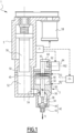
- FIG 1 represents a disclosed but unclaimed machine for product application 1, particularly high viscosity products such as glues or sealants (putty, etc.).
- the machine 1 comprises a product application device 3, and a product dosing system 5 supplied by a source of product to be applied (not shown).
- the dosing system 5 comprises a product inlet port 50, a product dosing chamber 52, and an outlet port 54 for the product towards the application device 3.
- the dosing system 5 comprises a dosing piston 56 , and a motor 58 actuating the movement of the metering piston 56 in the chamber 52 via a mechanical transformation system of the movement (for example a ball screw).
- the dosing system 5 is configured to send the product into the application device 3 with adjustable pressure.
- the speed and torque of the motor 58 are controlled to adjust the speed of movement of the metering piston 56, and the output pressure of the product from the outlet port 54.
- the application machine 1 comprises a control unit 7 configured to control the dosing system 5 and the application device 3.
- the control unit 7 can for this purpose be equipped with microprocessors, memories, calculation systems and communication configured to control the dosing system 5 and the application device 3 by electrical signals.
- the application device 3 comprises a frame 30 in which a control chamber 32 and a product conduit 34 are provided.
- the frame 30 defines a longitudinal bore 36 centered around a central axis X3, and which passes longitudinally through the frame 30 through the control chamber 32 and joins the conduit 34.
- the application device 3 comprises a needle 38 mounted in the longitudinal bore 36 in a sliding manner.
- the application device 3 also comprises a piston 40 housed in the control chamber 32 and secured to the needle 38 in its sliding along the axis X3.
- the application device 3 comprises a needle application valve 42, formed by a nozzle 43 provided on the frame 30 and a shutter 44 provided at one end of the needle 38 located in the conduit 34.
- the product conduit 34 guides the product between the outlet port 54 and the nozzle 43.
- the product is applied to its outlet from the nozzle 43 according to arrow F1.
- the shutter 44 is in this example formed by a ball, but can be of any other shape, in particular a cone, etc.
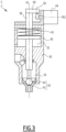
- the needle 38 moves along the longitudinal axis X3 between a closed position of the needle valve 42, shown in Figure 3 , and an opening position represented in figure 1 , under the action of a pilot fluid injected into the pilot chamber 32.
- the application device 3 comprises an elastic return element of the needle 38 in the closed position, formed for example by a spiral spring 45, housed in the control chamber 32.
- a control fluid is injected into the control chamber 32 according to the arrow F2
- the needle 38 is directed towards its open position against the force of the spring 45.
- a control fluid can also be injected into the control chamber 32 according to the arrow F3, to direct the needle 38 towards its closed position.
- the control fluid may be compressed air.
- the needle 38 returns to its closed position under the sole action of the spring 45.
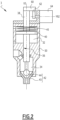
- the application device 3 comprises a stop 60 secured to the needle 38, and a stop 62 secured to the frame 30 configured to limit the return of the needle 38 towards its closed position to an intermediate position between the closed position and the position of opening, by cooperation with the stop 60 secured to the needle 38.
- the stop 60 is secured to the needle 38 in its sliding along the longitudinal axis X3.
- the stop 62 secured to the frame 30 has an adjustable position, that is to say that its position along the longitudinal axis X3 is fixed relative to the needle 38, except in an interval for adjusting its position along the longitudinal axis. X3. Adjusting the stop 62 makes it possible to prevent the needle valve 42 from completely closing, and therefore to reduce the product output flow in the nozzle 43.
- the stop 62 is set in the high position, and the needle 38 is also in the high position, the needle valve 42 being completely open.
- the stops 60 and 62 are not in contact.
- the stop 60 is in contact with the stop 62 in an intermediate position, which limits the return of the needle 38 in the low position to an intermediate position, the needle valve 42 is therefore not completely closed, and a flow restriction is therefore formed.
- the stop 62 is adjusted to the low position. This allows the complete return of the needle 38 to the low position, because the stop 62 no longer forms an obstacle to the descent of the stop 60 along the axis X3. The needle valve 42 is then completely closed.
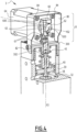
- the stop 60 is fixed to one end of the needle 38 projecting out of the frame 30, this end being opposite the shutter 44.
- the frame 30 comprises an upper cover 300, pierced with an orifice 302 through which the needle 38 slides along the longitudinal axis X3.
- the stop 60 is fixed to the needle 38 for example by two screws 61.
- the application device 3 comprises an actuator 64 for adjusting the position of the stop 62.
- the stop 62 is formed by at least one cam 63 movable in rotation around an axis of rotation Y62 perpendicular to the longitudinal axis X3.
- the actuator 64 is in this case formed by an electric motor rotating the cam 63 around the axis Y62.
- the rotation of the cam 63 around the axis Y62 makes it possible to adjust the angular position of the cam 63 and to modify the positioning along the axis X3 of the stop 62.
- the electric motor can be a stepper motor.
- the stop 62 may comprise two parallel cams 63, mounted on a common shaft 630 aligned with the adjustment axis Y62.
- the stop 60 has a contact surface 600 with the stop 62 which is inclined relative to the longitudinal axis X3.
- This inclined surface 600 allows that the variation of the height of the stop 62 along the longitudinal axis actuator 64. This also ensures that the point of contact between the cam 63 and the inclined surface 600 moves as little as possible from the longitudinal axis X3, while avoiding the design of a specific abutment surface 60.
- the surface 600 can be perpendicular to the longitudinal axis X3.
- the stop 60 has two parallel inclined surfaces 600 each cooperating with one of the cams 63.
- Cam 63 describes a curved surface of increasing radius around axis Y62.
- the angular position of the cam 63 around the axis Y62 varies the axial position, along the axis X3, of the stop 62, and the intermediate position to which the return of the needle 38 to its closed position is limited.
- the cams 63 are in a low position, that is to say an angular position in which they form a low obstacle, which does not oppose the descent of the stop 60.
- the needle 38 can therefore be in its closed position.
- the cams 63 are in an intermediate position corresponding to an angular position in which the radius of the cam surface aligned with the axis X3 is greater.
- the cams 63 form an obstacle located higher along the longitudinal axis Figure 4 .
- the cams 63 have undergone a rotation according to the arrow R1 at the figure 5 .
- the stop 60 is stopped at a higher position, preventing the needle valve 42 from closing and creating a flow restriction at the level of the nozzle 43.
- cams 63 have been positioned at an angular position in which the cam surface radius aligned with the axis X3 is maximum.
- the rotation of cams 63 along axis Y62 continued along arrow R1.
- the stop 62 retains the stop 60 in a high position, in which the opening of the needle valve 42 is maximum.
- the adjustment actuator 64, the stop 60 and the stop 62 form an external assembly 8 configured to be fixed and connected to the frame 30 and to the needle 38 of an existing application device 3.
- This assembly comprises a cover 80 which encloses the stop 60 and the stop 62, and which is fixed to the upper cover 300, for example by screws 82.
- the actuator 64 is fixed to the cover 80, for example by screws 84.
- the stops 60 and 62 and the actuator 64 can be easily adapted to an existing application device, the only constraint being external access to the needle 38. This access is not very restrictive compared to the specific technical solutions necessary to guarantee sealing, modification of the needle valve, and power of the actuators in the case of the current solutions mentioned above.
- the output flow D, the speed V and the pressure P5 are zero, and the needle 38 is in the closed position.
- the stop 62 is in its position of figures 3 And 4 , that is to say does not prevent the return of the needle 38 to the closed position.
- the deposit of product begins: the needle 38 is moved to open the needle valve 42 to 100%.
- the speed V is increased to generate a constant product pressure P52, and an outlet flow D1, corresponding to a fraction, for example 10%, of a maximum value D3 of the outlet flow D.
- the stop 62 remains in the low position .
- the stops 60 and 62 are implemented in transitional phases of the operation of the machine 1, when an increase or decrease in the output flow of the nozzle 43 must be obtained.
- a request to increase the output flow D at a time t6 is required.
- the flow must be increased quickly between D1 and D3.
- an increase in the outlet pressure P5 is generated by maintaining the speed V at a constant value V1 and reducing the opening of the needle valve 42.
- the stop 62 is gradually moved to a predefined position, while the machine 1 regulates the output flow D to the value D1.
- the positioning of stop 62 begins at t3.
- the predefined position of the stop 62 can for example correspond to a small opening of the needle valve 42, for example 10% of the maximum opening.
- the closing of the needle valve 42 is initiated.
- the stop 62 has reached its predefined position, and the needle 38 reaches the predefined position by the positioning of the stop 62.
- a flow restriction at the level of the nozzle 43 is therefore formed.
- the speed V being kept constant at V1, this has the effect of increasing the pressure P5 to a value P53 at time t5. Obtaining a greater flow rate requires a second prior pre-charge, while maintaining the output flow rate D constant.
- the needle valve 42 is again open 100%.
- the speed V is increased to a maximum value V3 to reach the value necessary to obtain the output flow D3.
- the opening of the needle valve 42 is 100%, the speed V3 is obtained, the pressure P5 has decreased to a value P54 of makes the opening of the needle valve 42, and the flow D3 is obtained.
- the time for obtaining the increase in output flow D between times t6 (opening of the needle valve 42) and t7 (obtaining the flow D3), is short, for example of the order of a few ms, which allows for a net increase in cord width. If such speed were to be obtained with actuators controlling a mechanical restriction at the nozzle 43, these would then have to be very powerful and expensive.
- the positioning of the stop 62 can be carried out in hidden time during a normal regulation phase. It is therefore not necessary to provide a powerful actuator for its movement. Between time t3 and time t6, a few tens of ms may be sufficient to position stop 62. This is a switching time which remains compatible with a standard, inexpensive stepper motor, which can therefore be used for actuator 64.
- the output flow D must be reduced to an intermediate value D2 lower than D3, for example 20% of the flow D3.
- the control unit 7 generates a reduction in outlet pressure P5.
- This reduction in pressure is rapid: the speed V is quickly reduced to a low value.
- the speed V is reduced to the low value within a few ms.
- the speed reduction V begins at time t8 and ends at time t9.
- the low value to which the speed V is reduced can be less than zero as illustrated at time t9 at the figure 7 , the direction of movement of the motor 58 can therefore be reversed, in cases where a strong reduction in flow is desired.
- the low value can be a zero speed, or for example a speed less than 10% of the maximum value of the speed V, for example when the desired flow variation is less abrupt.
- the opening of the needle valve 42 is reduced.
- This opening reduction is obtained by positioning the stop 62 at a predefined intermediate position corresponding for example to 20% of the total opening of the needle valve 42, and by closing, at time t8, the needle valve 42 by actuating the needle 38 towards the closed position until it is blocked by the stop 62 at the predefined position at 20%, at time t9.
- the start of positioning of the stop 62 takes place before time t8, and can for example start from the position at 10% opening, at time t6, so that the actuator 64 has sufficient time to position the stop 62.
- We thus obtain a rapid reduction in the outlet flow D.
- the needle valve 42 is opened again at a time t10, and the speed V is increased again from time t9 to a value V2 necessary to obtain the output flow D2.
- the speed V is stabilized, the pressure P5 is stabilized at a value P55, and the needle 38 is positioned at its 100% open position.
- the control process can then be resumed as it started at t0, by a new pre-charge by increasing the speed V to t16.
- a new bead of product can then be deposited, with the output flow D3, at t17.
- speed V is suddenly reversed, to obtain rapid decompression and the end of the product bead at t19.
- the stop 62 is not used in this phase.
- the application device 3 equipped with stops 60 and 62 can therefore operate in a classic use case.
- control unit 7 All the operating steps described above are triggered at the control unit 7 by control signals sent to the motor 58, to a pilot fluid distributor 9 controlling the movement of the needle 38, for example a pneumatic distributor , and to the actuator 64.
- a second embodiment according to the invention is shown on the figure 8 .
- the position of the stop 62 secured to the frame 30 is adjustable around an adjustment axis X62 parallel to the longitudinal axis X3 of the needle 38.
- the stop is formed by a cam surface 620 whose height , along axis X62, is variable depending on its angular position around axis X62.
- the cam surface 620 On an angular portion, the cam surface 620 has a recess 622 of small thickness which does not prevent the descent of the needle 38.
- the cam surface 620 On an angular portion opposite to the axis X62, the cam surface 620 has a maximum thickness , which forms a limitation on the return to the closed position of the needle 38.
- the actuator 64 is a hollow shaft motor forming a tubular part 640 rotatably mounted around a part of the needle 38 projecting out of the frame 30.
- This tubular part 640 carries the stop 62, which has a cam surface 620 similar to that of the embodiment of the figure 8 .
- the angular position of the cam surface 620 is adjustable around the longitudinal axis X3 of the needle 38, the adjustment axis X64 and the longitudinal axis X3 being the same.
- the height along the longitudinal axis X3 of the cam surface 620 is variable around the adjustment axis X64. This embodiment guarantees radial and axial compactness of the application device 3.
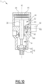
- a fourth embodiment disclosed but not claimed is shown in the Figure 10 .
- the stop 62 secured to the frame 30 is provided in the control chamber 32.
- the cam 63 forming the stop 63 is movable in rotation around the adjustment axis Y62 oriented perpendicular to the longitudinal axis X3.
- the cam 63 projects into the control chamber 32 so as to limit the downward translation of the piston 40.
- the stop secured to the needle 38 is therefore formed by the piston 40 itself.
- a cavity 320 is provided in the frame 30 to allow the rotation of the cam 63 around the adjustment axis Y62.
- the adjustment actuator is a linear actuator 66, that is to say exerting a movement in translation, for example a jack or a ball screw.
- the stop 62 integral with the frame 30 is formed by a part 642 movable in translation along the adjustment axis X62 which is then parallel or coincident with the longitudinal axis projecting outside the frame 30, and around which the spring 45 winds.
- the cylindrical part 400 comprises at its upper end a cavity 402 in which the part 642 is received.
- the cavity 402 comprises a radial part 404 oriented towards the interior, which forms the stop 60 integral with the needle 38.
Landscapes
- Engineering & Computer Science (AREA)
- Coating Apparatus (AREA)
- Manufacturing & Machinery (AREA)
- Microelectronics & Electronic Packaging (AREA)
- Application Of Or Painting With Fluid Materials (AREA)
Description
- La présente invention concerne un dispositif d'application d'un produit, une machine d'application de produit comprenant un tel dispositif et un procédé de contrôle d'une telle machine.
- Dans le domaine de l'application de produits de collage ou d'étanchéité par des systèmes robotisés, il peut être nécessaire de modifier rapidement le débit d'application pour par exemple, obtenir un cordon de colle ou de mastic plus large ou plus étroit. Cette modification de largeur doit être rapide pour garantir des résultats propres et éviter des pertes de produits coûteux. Ces produits étant visqueux, des systèmes doivent être conçus spécifiquement.
- Les systèmes de dosage électrique du produit ou de régulation de pression sont actionnés par des moteurs. Dans le cas d'applications peu dynamiques et proches du système de dosage, la vitesse du moteur est proportionnelle au débit de sortie du produit. Dans le cas d'applications plus dynamiques ou lorsque l'application est éloignée du système de dosage, les systèmes de dosage ou de régulation de pression ont des temps de réaction relativement importants du fait de la compressibilité des produits, de l'élasticité des flexibles et des hautes pressions en jeu.
- Pour obtenir des changements de débit rapide, il est connu d'utiliser des systèmes mécaniques créant des restrictions réglables avant les buses d'application de produit, avec des pièces mobiles. De telles solutions présentent plusieurs désavantages :
- Il n'est pas possible d'arrêter rapidement la dépose de produit du fait du volume à décompresser entre la restriction et la buse. La fin de cordon d'application n'est donc pas nette.
- Les produits sont abrasifs et causent de l'usure sur les pièces mobiles et des fuites.
- Les actionneurs nécessaires pour le déplacement des pièces mobiles doivent être rapides et puissants et sont donc coûteux.
- Des joints spécifiques doivent être conçus pour toutes les pièces mobiles, ce qui engendre un surcoût.
- Le pointeau et le siège de la vanne doivent être spécifiquement conçus, ce qui ne permet pas d'utiliser un dispositif d'application à débit non variable préexistant.
- Le document
DE 102 16 631 A1 décrit un dispositif pour le huilage de surfaces de planches, comprenant une tête de buse. La tête de buse s'appuie sur son côté opposé à l'extrémité de buse contre un excentrique qui peut être mis en rotation par un moteur pour déplacer l'aiguille de buse contre la force d'un accumulateur d'énergie pour passer en position ouverte, en position fermée ou dans une position intermédiaire entre les deux. - L'objectif de l'invention est de proposer un nouveau dispositif d'application de produit, permettant d'obtenir des variations rapides de débit d'application de produit, avec des pièces mécaniques dont le coût et la complexité sont faibles par rapport aux solutions existantes, de meilleures performances et une meilleure fiabilité.
- A cet effet, l'invention concerne un dispositif d'application de produit, selon la revendication 1.
- Grâce à l'invention, le positionnement du pointeau à des positions intermédiaires permet de créer une restriction réglable ne nécessitant pas d'actionneurs coûteux ou de conceptions spécifiques de solutions d'étanchéité.
- Selon des aspects avantageux mais non obligatoires de l'invention, un tel dispositif d'application de produit peut incorporer une ou plusieurs des caractéristiques des revendications 2 à 7, prises dans toutes combinaisons techniquement admissibles.
- L'invention concerne également une machine d'application de produit selon la revendication 8.
- L'invention concerne également un procédé de contrôle d'une machine d'application de produit selon la revendication 9.
- Selon des aspects avantageux mais non obligatoires de l'invention, un tel procédé de contrôle peut incorporer une ou plusieurs des caractéristiques des revendications 10 et 11, prises dans toutes combinaisons techniquement admissibles.
- L'invention sera mieux comprise et d'autres avantages de celle-ci apparaitront plus clairement à la lumière de la description qui va suivre d'un dispositif d'application de produit, d'une machine d'application de produit et d'un procédé de contrôle conformes à son principe, faite à titre d'exemple non limitatif en référence aux dessins annexés dans lesquels :
- [
Fig 1 ] LaFigure 1 est une coupe schématique d'une machine d'application de produit divulgué mais non revendiqué, comprenant un dispositif d'application de produit conforme à un premier mode de réalisation divulgué mais non revendiqué, le dispositif d'application de produit étant dans une configuration ouverte; - [
Fig 2 ] Lafigure 2 est une coupe schématique du dispositif d'application de produit de lafigure 1 dans une configuration intermédiaire ; - [
Fig 3 ] Lafigure 3 est une coupe vue schématique du dispositif d'application de produit de lafigure 3 dans une configuration fermée - [
Fig 4 ] Lafigure 4 est une vue en perspective partiellement sectionnée du dispositif d'application de lafigure 1 , montrant une butée dans une configuration basse en configuration fermée du dispositif; - [
Fig 5 ] Lafigure 5 est une vue en perspective partiellement sectionnée du dispositif d'application de lafigure 1 montrant la butée dans une configuration intermédiaire; - [
Fig 6 ] Lafigure 6 est une vue en perspective partiellement sectionnée du dispositif d'application de lafigure 1 , montrant la butée dans une configuration d'ouverture maximale; - [
Fig 7 ] LaFigure 7 est un graphique de fonctionnement d'une méthode de contrôle d'une machine d'application conforme à l'invention ; - [
Fig 8 ] LaFigure 8 est une coupe schématique d'un dispositif d'application de produit conforme à un deuxième mode de réalisation de l'invention ; - [
Fig 9 ] LaFigure 9 est une coupe schématique d'un dispositif d'application de produit conforme à un troisième mode de réalisation de l'invention ; - [
Fig 10 ] LaFigure 10 est une coupe schématique d'un dispositif d'application de produit conforme à un quatrième mode de réalisation divulgué mais non revendiqué ; - [
Fig 11 ] LaFigure 11 est une coupe schématique d'un dispositif d'application de produit conforme à un cinquième mode de réalisation divulgué mais non revendiqué. - La
figure 1 représente une machine divulgué mais non revendiqué d'application 1 de produit, notamment des produits à haute viscosité tels que les colles ou les produits d'étanchéité (mastic, etc.). La machine 1 comprend un dispositif d'application 3 de produit, et un système de dosage 5 du produit alimenté par une source de produit à appliquer (non représentée). - Le système de dosage 5 comprend un port 50 d'entrée de produit, une chambre 52 de dosage du produit, et un port de sortie 54 du produit vers le dispositif d'application 3. Le système de dosage 5 comprend un piston de dosage 56, et un moteur 58 actionnant le déplacement du piston de dosage 56 dans la chambre 52 par l'intermédiaire d'un système de transformation mécanique du mouvement (par exemple une vis à billes).
- Le système de dosage 5 est configuré pour envoyer le produit dans le dispositif d'application 3 avec une pression réglable. La vitesse et le couple du moteur 58 sont pilotés pour régler la vitesse de déplacement du piston de dosage 56, et la pression de sortie du produit du port de sortie 54.
- La machine d'application 1 comprend une unité de contrôle 7 configurée pour contrôler le système de dosage 5 et le dispositif d'application 3. L'unité de contrôle 7 peut être à cet effet équipée de microprocesseurs, de mémoires, de systèmes de calcul et de communication configurés pour contrôler le système de dosage 5 et le dispositif d'application 3 par des signaux électriques.
- Le dispositif d'application 3 comprend un bâti 30 dans lequel sont prévus une chambre de pilotage 32 et un conduit de produit 34. Le bâti 30 définit un alésage longitudinal 36 centré autour d'un axe central X3, et qui traverse longitudinalement le bâti 30 à travers la chambre de pilotage 32 et rejoint le conduit 34. Le dispositif d'application 3 comprend un pointeau 38 monté dans l'alésage longitudinal 36 de façon coulissante. Le dispositif d'application 3 comprend également un piston 40 logé dans la chambre de pilotage 32 et solidaire du pointeau 38 dans son coulissement selon l'axe X3.
- Le dispositif d'application 3 comprend une vanne d'application à pointeau 42, formée par une buse 43 prévue sur le bâti 30 et un obturateur 44 prévu à une extrémité du pointeau 38 située dans le conduit 34. Le conduit de produit 34 guide le produit entre le port de sortie 54 et la buse 43. Le produit est appliqué à sa sortie de la buse 43 selon la flèche F1. L'obturateur 44 est dans cet exemple formé par une bille, mais peut être de toute autre forme, notamment un cône, etc.
- Le pointeau 38 se déplace le long de l'axe longitudinal X3 entre une position de fermeture de la vanne à pointeau 42, représentée à la
figure 3 , et une position d'ouverture représentée à lafigure 1 , sous l'action d'un fluide de pilotage injecté dans la chambre de pilotage 32. Le dispositif d'application 3 comprend un élément de rappel élastique du pointeau 38 en position fermée, formé par exemple par un ressort spiral 45, logé dans la chambre de pilotage 32. Lorsque qu'un fluide de pilotage est injecté dans la chambre de pilotage 32 selon la flèche F2, le pointeau 38 est dirigé vers sa position ouverte à l'encontre de l'effort du ressort 45. Un fluide de pilotage peut également être injecté dans la chambre de pilotage 32 selon la flèche F3, pour diriger le pointeau 38 vers sa position fermée. Le fluide de commande peut être de l'air comprimé. - Selon une variante non représentée, le pointeau 38 retourne à sa position fermée sous l'action unique du ressort 45.
- Le dispositif d'application 3 comprend une butée 60 solidaire du pointeau 38, et une butée 62 solidaire du bâti 30 configurée pour limiter le retour du pointeau 38 vers sa position de fermeture à une position intermédiaire entre la position de fermeture et la position d'ouverture, par coopération avec la butée 60 solidaire du pointeau 38. La butée 60 est solidaire du pointeau 38 dans son coulissement selon l'axe longitudinal X3. La butée 62 solidaire du bâti 30 a une position réglable, c'est-à-dire que sa position selon l'axe longitudinal X3 est fixe par rapport au pointeau 38, hormis dans un intervalle de réglage de sa position selon l'axe longitudinal X3. Le réglage de la butée 62 permet d'empêcher la fermeture complète de la vanne à pointeau 42, et donc de réduire le débit de sortie de produit dans la buse 43.
- A la
figure 1 , la butée 62 est réglée en position haute, et le pointeau 38 est également en position haute, la vanne à pointeau 42 étant complètement ouverte. Les butées 60 et 62 ne sont pas en contact. A lafigure 2 , la butée 60 est en contact avec la butée 62 dans une position intermédiaire, ce qui limite le retour du pointeau 38 en position basse à une position intermédiaire, la vanne à pointeau 42 n'est donc pas complètement fermée, et une restriction de débit est donc formée. A lafigure 3 , la butée 62 est réglée en position basse. Cela permet le retour complet du pointeau 38 en position basse, car la butée 62 ne forme plus d'obstacle à la descente de la butée 60 selon l'axe X3. La vanne à pointeau 42 est alors complètement fermée. - Selon un mode de réalisation divulgué mais non revendiqué représenté sur les
figures 4 à 6 , la butée 60 est fixée à une extrémité du pointeau 38 faisant saillie hors du bâti 30, cette extrémité étant opposée à l'obturateur 44. Le bâti 30 comporte un couvercle supérieur 300, percé d'un orifice 302 à travers lequel le pointeau 38 coulisse selon l'axe longitudinal X3. La butée 60 est fixée au pointeau 38 par exemple par deux vis 61. - Le dispositif d'application 3 comprend un actionneur 64 de réglage de la position de la butée 62. Selon un mode de réalisation, la butée 62 est formée par au moins une came 63 mobile en rotation autour d'un axe de rotation Y62 perpendiculaire à l'axe longitudinal X3. L'actionneur 64 est dans ce cas formé par un moteur électrique entraînant en rotation la came 63 autour de l'axe Y62. La rotation de la came 63 autour de l'axe Y62 permet de régler la position angulaire de la came 63 et de modifier le positionnement selon l'axe X3 de la butée 62. Le moteur électrique peut être un moteur pas-à-pas.
- Comme cela est visible aux
figures 4 à 6 , la butée 62 peut comprendre deux cames parallèles 63, montées sur un arbre commun 630 aligné avec l'axe de réglage Y62. - Selon un mode de réalisation, la butée 60 présente une surface 600 de contact avec la butée 62 qui est inclinée par rapport à l'axe longitudinal X3. Cette surface 600 inclinée permet que la variation de la hauteur de la butée 62 selon l'axe longitudinal X3 en fonction de la position angulaire de la came 63 soit la plus constante possible, dans le but d'améliorer la précision et la simplicité du pilotage de la came 63 par l'actionneur 64. Ceci permet également de garantir que le point de contact entre la came 63 et la surface inclinée 600 s'éloigne le moins possible de l'axe longitudinal X3, tout en évitant la conception d'une surface de butée 60 spécifique.
- En variante non représentée, la surface 600 peut être perpendiculaire à l'axe longitudinal X3.
- La butée 60 présente deux surfaces inclinées parallèles 600 coopérant chacune avec l'une des cames 63.
- La came 63 décrit une surface courbe de rayon croissant autour de l'axe Y62. La position angulaire de la came 63 autour de l'axe Y62 fait varier la position axiale, selon l'axe X3, de la butée 62, et la position intermédiaire à laquelle est limité le retour du pointeau 38 vers sa position fermée.
- A la
figure 4 , les cames 63 sont dans une position basse, c'est-à-dire une position angulaire dans laquelle elles forment un obstacle bas, qui ne s'oppose pas à la descente de la butée 60. Le pointeau 38 peut donc être dans sa position fermée. - A la
figure 5 , les cames 63 sont dans une position intermédiaire correspondant à une position angulaire dans laquelle le rayon de la surface de came aligné avec l'axe X3 est plus grand. Les cames 63 forment un obstacle situé plus haut le long de l'axe longitudinal X3 par rapport à lafigure 4 . Entre lafigure 4 et lafigure 5 , les cames 63 ont subi une rotation selon la flèche R1 à lafigure 5 . Dans cette position des cames 63, la butée 60 est arrêtée à une position plus élevée, empêchant la vanne à pointeau 42 de se refermer et créant une restriction de débit au niveau de la buse 43. - A la
figure 6 , les cames 63 ont été positionnées à une position angulaire dans laquelle le rayon de surface de came aligné avec l'axe X3 est maximal. La rotation des cames 63 selon l'axe Y62 s'est poursuivie selon la flèche R1. Dans cette position, la butée 62 retient la butée 60 dans une position haute, dans laquelle l'ouverture de la vanne à pointeau 42 est maximale. - Selon un mode de réalisation, l'actionneur de réglage 64, la butée 60 et la butée 62 forment un ensemble externe 8 configuré pour être fixé et relié au bâti 30 et au pointeau 38 d'un dispositif d'application 3 existant. Cet ensemble comporte un capot 80 qui renferme la butée 60 et la butée 62, et qui est fixé au couvercle supérieur 300, par exemple par des vis 82. L'actionneur 64 est fixé au capot 80, par exemple par des vis 84. Sous la forme de l'ensemble externe 8, les butées 60 et 62 et l'actionneur 64 peuvent être facilement adaptés à un dispositif d'application existant, la seule contrainte étant un accès extérieur au pointeau 38. Cet accès est peu contraignant en comparaison des solutions techniques spécifiques nécessaires pour garantir l'étanchéité, la modification de la vanne à pointeau, et la puissance des actionneurs dans le cas des solutions actuelles mentionnées précédemment.
- Le fonctionnement de la machine 1 est décrit en référence à la
figure 7 . - La
figure 1 présente en abscisse le temps, et en ordonnées, de bas en haut : - La largeur L du cordon de produit déposé par le dispositif d'application 3 ;
- Le débit de sortie D de la buse 43 ;
- La vitesse angulaire V du moteur 58 représentative de la vitesse linéaire du piston 56;
- La position P du pointeau 38, avec sous forme d'aire hachurée, la position de la butée 62 solidaire du bâti 30 ;
- La pression relative à la pression atmosphérique P5 de produit présente en sortie du système de dosage 5.
- A un temps t0, par exemple correspondant à l'allumage de la machine 1, le débit de sortie D, la vitesse V et la pression P5 sont nuls, et le pointeau 38 est en position fermée. La butée 62 est dans sa position des
figures 3 et4 , c'est-à-dire n'empêche pas le retour du pointeau 38 en position fermée. - Pour obtenir un premier cordon de produit, il est nécessaire d'avoir une certaine pression P5 dans le dispositif d'application 3 légèrement supérieure à la pression d'application souhaitée après ouverture de la vanne à pointeau 42. On applique donc une pré-charge initiale. Cette pré-charge est obtenue en actionnant rapidement le moteur 58. La vitesse V est donc augmentée à un temps t1, puis revient à zéro à un temps t2, le pointeau 38 restant en position et la vanne à pointeau 42 restant donc fermée afin d'obtenir une pression P51.
- A un temps t3, la dépose de produit commence : le pointeau 38 est déplacé pour ouvrir la vanne à pointeau 42 à 100%. La vitesse V est augmentée pour générer une pression de produit constante P52, et un débit de sortie D1, correspondant à une fraction, par exemple 10%, d'une valeur maximale D3 du débit de sortie D. La butée 62 reste en position basse.
- Les butées 60 et 62 sont mises en oeuvre dans des phases transitoires du fonctionnement de la machine 1, lorsqu'une augmentation ou une diminution du débit de sortie de la buse 43 doit être obtenu.
- Une demande d'augmentation du débit de sortie D à un temps t6 est requise. Le débit doit être augmenté rapidement entre D1 et D3. Pour cela, en avance du temps t6, on génère une augmentation de la pression de sortie P5 par le maintien à une valeur constante V1 de la vitesse V et la réduction de l'ouverture de la vanne à pointeau 42. Pour cela, la butée 62 est progressivement déplacée à une position prédéfinie, pendant que la machine 1 régule le débit de sortie D à la valeur D1. Le positionnement de la butée 62 débute à t3. La position prédéfinie de la butée 62 peut par exemple correspondre à une ouverture faible de la vanne à pointeau 42, par exemple de 10% de l'ouverture maximale.
- A un temps t4, la fermeture de la vanne à pointeau 42 est initiée. A un temps t5, la butée 62 a atteint sa position prédéfinie, et le pointeau 38 atteint jusqu'à la position prédéfinie par le positionnement de la butée 62. Une restriction de débit au niveau de la buse 43 est donc formée. La vitesse V étant maintenue constante à V1, ceci a pour effet d'augmenter la pression P5 jusqu'à une valeur P53 au temps t5. L'obtention d'un débit plus important nécessite une seconde pré-charge préalable, tout en maintenant constant le débit de sortie D.
- Au temps t6, la pression P53 nécessaire étant obtenue, la vanne à pointeau 42 est à nouveau ouverte à 100%. La vitesse V est augmentée à une valeur maximale V3 pour atteindre la valeur nécessaire à l'obtention du débit de sortie D3. A un temps t7, l'ouverture de la vanne à pointeau 42 est de 100%, la vitesse V3 est obtenue, la pression P5 a diminué à une valeur P54 du fait de l'ouverture de la vanne à pointeau 42, et le débit D3 est obtenu. Le temps d'obtention de l'augmentation de débit de sortie D, entre les temps t6 (ouverture de la vanne à pointeau 42) et t7 (obtention du débit D3), est court, par exemple de l'ordre de quelques ms, ce qui permet d'avoir une augmentation de largeur de cordon nette. Si une telle rapidité devait être obtenue avec des actionneurs pilotant une restriction mécanique au niveau de la buse 43, ceux-ci devraient alors être très puissants et coûteux.
- A l'inverse, le positionnement de la butée 62 peut être réalisé en temps masqué pendant une phase de régulation normale. Il n'est donc pas nécessaire de prévoir un actionneur puissant pour son déplacement. Entre le temps t3 et le temps t6, quelques dizaines de ms peuvent être suffisants pour positionner la butée 62. C'est un temps de commutation qui reste compatible avec un moteur pas-à-pas standard, peu coûteux, qui peut donc être utilisé pour l'actionneur 64.
- Une phase transitoire de diminution du débit de sortie D est à présent décrite. Le débit de sortie D doit être diminué à une valeur intermédiaire D2 inférieure à D3, par exemple 20% du débit D3. Pour cela, l'unité de contrôle 7 génère une réduction de pression de sortie P5. Cette réduction de pression est rapide : la vitesse V est rapidement réduite à une valeur basse. Par exemple, la vitesse V est réduite à la valeur basse en quelques ms. La réduction de vitesse V débute à un temps t8 et se termine à un temps t9. La valeur basse à laquelle est réduite la vitesse V peut être inférieur à zéro comme illustré au temps t9 à la
figure 7 , le sens de marche du moteur 58 peut donc être inversé, dans les cas où une forte réduction de débit est souhaitée. En variante, la valeur basse peut être une vitesse nulle, ou bien par exemple une vitesse inférieure à 10 % de la valeur maximale de la vitesse V, par exemple lorsque la variation de débit souhaitée est moins brusque. - Simultanément, l'ouverture de la vanne à pointeau 42 est réduite. Cette réduction d'ouverture est obtenue en positionnant la butée 62 à une position intermédiaire prédéfinie correspondant par exemple à 20% de l'ouverture totale de la vanne à pointeau 42, et en fermant, au temps t8, la vanne à pointeau 42 en actionnant le pointeau 38 vers la position fermée jusqu'à ce qu'il soit bloqué par la butée 62 à la position prédéfinie à 20%, au temps t9. Le début du positionnement de la butée 62 a lieu préalablement au temps t8, et peut par exemple démarrée à partie de la position à 10% d'ouverture, au temps t6, de manière que l'actionneur 64 ait suffisamment de temps pour positionner la butée 62. On obtient ainsi une réduction rapide du débit de sortie D. On entre ensuite dans une phase de régulation normale du débit de sortie D à la valeur D2. Pour cela, la vanne à pointeau 42 est ouverte à nouveau à un temps t10, et la vitesse V est à nouveau augmentée à partir du temps t9 jusqu'à une valeur V2 nécessaire à l'obtention du débit de sortie D2. A un temps t11, la vitesse V est stabilisée, la pression P5 est stabilisée à une valeur P55, et le pointeau 38 est positionné à sa position d'ouverture à 100%.
- Entre les temps t12 et t13 sont opérés à nouveau par l'unité de contrôle 7 les étapes déjà décrites pour l'augmentation du débit de sortie D entre D1 et D3: afin de rétablir le débit de sortie D à D3, la vitesse V est maintenue constante, et la pression P5 est à nouveau augmentée à la valeur P53 par la fermeture partielle de la vanne à pointeau 42 jusqu'à la valeur d'ouverture intermédiaire fixée par le positionnement de la butée 62, qui est restée en place. A t13, un régime de régulation normal s'établit avec le débit de sortie D à D3.
- A des temps ultérieurs t14 et t15 sont à nouveau opérées des réductions rapides de la vitesse V et des fermetures partielles de la vanne à pointeau 42 pour obtenir successivement une réduction du débit de sortie D à D1, puis à zéro. Au temps t13, ou bien un peu avant, la butée 62 a été progressivement descendue pour fixer à t14 une position d'arrêt du pointeau 38 correspondant à l'ouverture faible de la vanne à pointeau 42, par exemple 10%. Après le temps t14, la butée 62 a été progressivement descendue jusqu'à sa position basse pour permettre la fermeture complète de la vanne à pointeau 42 à t15, et la fin du cordon de produit. Au temps t15, la vitesse V est brutalement réduite jusqu'à une valeur négative, ce qui revient à retirer le piston 56 vers le haut, pour obtenir une rapide décompression dans le conduit 34 du dispositif d'application 3.
- Le procédé de contrôle peut ensuite être repris tel qu'il a commencé à t0, par une nouvelle pré-charge par l'augmentation de la vitesse V à t16. Un nouveau cordon de produit peut ensuite être déposé, avec le débit de sortie D3, à t17. A un temps t18, la vitesse V est brutalement inversée, pour obtenir une décompression rapide et la fin du cordon de produit à t19. Dans la mesure où il n'y a pas de variations du débit de sortie D entre des valeurs intermédiaires entre t17 et t19, la butée 62 n'est pas utilisée dans cette phase. Le dispositif d'application 3 équipé des butées 60 et 62 peut donc fonctionner dans un cas d'utilisation classique.
- Toutes les étapes de fonctionnement décrites ci-dessus sont déclenchées au niveau de l'unité de contrôle 7 par des signaux de contrôle envoyés au moteur 58, à un distributeur 9 de fluide de pilotage contrôlant le déplacement du pointeau 38, par exemple un distributeur pneumatique, et à l'actionneur 64.
- L'invention procure les avantages suivants :
- Les fermetures complètes de la vanne à pointeau 42 sont rapides lorsque la butée 62 est en position basse, et il n'y a pas de création de volume mort de produit entre l'amont de la buse 43 et la buse 43. Les fins de cordons de produit sont donc nettes.
- Il n'y a pas de création d'usures spécifiques dues à des pièces mobiles supplémentaires au niveau de la buse 43 : La vanne à pointeau 42 aura donc une longévité normale.
- L'actionneur 64 n'a pas besoin d'être puissant, car les pré-positionnements de la butée 62 sont faits en temps masqué pendant des durées plus longues que les changements brusques de débit de sortie de produit. En outre, les positionnements de la butée 62 sont faits pendant que la vanne à pointeau 42 est ouverte, ce qui ne génère pas d'efforts sur la came de la butée 62.
- Les systèmes d'étanchéités conventionnels de la vanne à pointeau 42 peuvent être utilisés, et il n'y a pas de nécessité de concevoir des systèmes d'étanchéité spécifiques.
- Les butées 60 et 62 ainsi que l'actionneur 64 peuvent être adaptés sous la forme de l'ensemble 8 sur un dispositif d'application préexistant en prévoyant seulement un accès au pointeau 38 ou au piston 40.
- D'autres modes de réalisation du dispositif d'application de produit sont représentés sur les
figures 8 à 11 . Dans ces modes de réalisation, les éléments communs au premier mode de réalisation portent les mêmes références et fonctionnent de la même manière. - Un deuxième mode de réalisation selon l'invention est représenté sur la
figure 8 . Dans ce mode de réalisation, la position de la butée 62 solidaire du bâti 30 est réglable autour d'un axe de réglage X62 parallèle à l'axe longitudinal X3 du pointeau 38. La butée est formée par une surface de came 620 dont la hauteur, selon l'axe X62, est variable en fonction de sa position angulaire autour de l'axe X62. Sur une portion angulaire, la surface de came 620 présente un décrochement 622 de faible épaisseur qui n'empêche pas la descente du pointeau 38. Sur une portion angulaire opposée par rapport à l'axe X62, la surface de came 620 présente une épaisseur maximale, qui forme une limitation au retour en position fermée du pointeau 38. - Un troisième mode de réalisation selon l'invention est représenté sur la
figure 9 . Dans ce mode de réalisation, l'actionneur 64 est un moteur à axe creux formant une pièce tubulaire 640 montée de façon rotative autour d'une partie du pointeau 38 faisant saillie hors du bâti 30. Cette pièce tubulaire 640 porte la butée 62, qui présente une surface de came 620 similaire à celle du mode de réalisation de lafigure 8 . Dans ce cas, la position angulaire de la surface de came 620 est réglable autour de l'axe longitudinal X3 du pointeau 38, l'axe de réglage X64 et l'axe longitudinal X3 étant confondus. La hauteur selon l'axe longitudinal X3 de la surface de came 620 est variable autour de l'axe de réglage X64. Ce mode de réalisation garantit une compacité radiale et axiale du dispositif d'application 3. - Un quatrième mode de réalisation divulgué mais non revendiqué est représenté sur la
figure 10 . Dans ce mode de réalisation, la butée 62 solidaire du bâti 30 est prévue dans la chambre de pilotage 32. La came 63 formant la butée 63 est mobile en rotation autour de l'axe de réglage Y62 orienté perpendiculairement à l'axe longitudinal X3. La came 63 fait saillie dans la chambre de pilotage 32 de manière à limiter la translation du piston 40 vers le bas. Dans ce cas, la butée solidaire du pointeau 38 est donc formée par le piston 40 lui-même. Une cavité 320 est prévue dans le bâti 30 pour permettre la rotation de la came 63 autour de l'axe de réglage Y62. - Un cinquième mode de réalisation divulgué mais non revendiqué est représenté sur la
figure 11 . Dans ce mode de réalisation, l'actionneur de réglage est un actionneur linéaire 66, c'est-à-dire exerçant un déplacement en translation, par exemple un vérin ou une vis à billes. La butée 62 solidaire du bâti 30 est formée par une pièce 642 mobile en translation selon l'axe de réglage X62 qui est alors parallèle ou confondu avec l'axe longitudinal X3 du pointeau 38. Le piston 40 comporte une partie cylindrique 400 s'étendant en saillie en dehors du bâti 30, et autour de laquelle s'enroule le ressort 45. La partie cylindrique 400 comprend à son extrémité supérieure une cavité 402 dans laquelle est reçue la pièce 642. La cavité 402 comprend une partie radiale 404 orientée vers l'intérieur, qui forme la butée 60 solidaire du pointeau 38. Lorsque le pointeau 38 retourne vers sa position fermée, la pièce 642 s'oppose selon l'axe longitudinal X3 à la partie radiale 404 et limite la fermeture de la vanne à pointeau 42. - Les caractéristiques techniques des modes de réalisation et variantes décrits ci-dessus peuvent être combinées pour former d'autres modes de réalisation de l'invention dans le cadre des revendications.
Claims (11)
- Dispositif d'application (3) de produit, comprenant un bâti (30) dans lequel est prévu un conduit (34) de produit, le bâti (30) définissant un alésage longitudinal (36), le dispositif d'application (3) comprenant un pointeau (38) monté dans l'alésage longitudinal (36), le dispositif d'application comprenant une vanne d'application (42) de produit formée par une buse (43) prévue sur le bâti (30) et un obturateur (44) prévu à une extrémité du pointeau (38) située dans le conduit (34) de produit, le pointeau étant configuré pour être déplacé le long d'un axe longitudinal (X3) entre une position de fermeture de la vanne d'application (42) et une position d'ouverture, dans lequel le dispositif d'application (3) comprend une butée (60 ; 40) solidaire du pointeau (38), et une butée (62) solidaire du bâti (30) configurée pour limiter le retour du pointeau (38) vers sa position de fermeture à une position intermédiaire entre la position de fermeture et la position d'ouverture, par coopération avec la butée (60 ; 40) solidaire du pointeau (38), la butée (62) solidaire du bâti (30) ayant une position réglable, la butée (62) solidaire du bâti (30) étant formée par au moins une came (63), le dispositif d'application (3) comprenant un actionneur (64) de réglage de la position de la came (63), caractérisé en ce que la position de la came (63) est réglable en rotation autour d'un axe de réglage (X62) parallèle à l'axe longitudinal (X3) du pointeau (38), et en ce que l'épaisseur de la came est croissante autour de l'axe de réglage.
- Dispositif d'application selon la revendication 1, caractérisé en ce que l'actionneur de réglage (64) est un moteur électrique rotatif.
- Dispositif d'application selon la revendication 2, caractérisé en ce que la came est portée par une pièce tubulaire (640) montée autour d'une partie du pointeau (38) faisant saillie hors du bâti (30), en ce que l'actionneur (64) est un moteur à axe creux entrainant la pièce tubulaire (640), la position angulaire de la came étant réglable autour de l'axe longitudinal (X3) du pointeau (38), et en ce que l'épaisseur de la came est croissante autour de l'axe de réglage.
- Dispositif d'application selon l'une des revendications précédentes, caractérisé en ce que la butée (60) solidaire du pointeau (38) est fixée à une extrémité du pointeau (38) faisant saillie hors du bâti (30).
- Dispositif d'application selon la revendication 4, caractérisé en ce que l'actionneur de réglage (64), la butée (60) solidaire du pointeau (38) et la butée (62) solidaire du bâti (30) forment un ensemble externe (8) configuré pour être fixé et relié au bâti (30) et au pointeau (38) d'un dispositif d'application (3) existant.
- Dispositif d'application selon l'une des revendications 1 à 3, caractérisé en ce que la butée solidaire du pointeau (38) est formée par un piston (40) logé dans une chambre de pilotage (32) du bâti (30), et en ce que la butée (62) solidaire du bâti (30) est prévue dans le bâti (30) et fait saillie dans la chambre de pilotage (32).
- Dispositif d'application selon l'une des revendications précédentes, caractérisé en ce que la butée (60) solidaire du pointeau (38) présente une surface (600) inclinée par rapport à l'axe longitudinal (X3) du pointeau (38).
- Machine d'application (1) de produit comprenant : un dispositif d'application (3) selon l'une des revendications précédentes, et un système de dosage (5) du produit, le système de dosage (5) étant configuré pour envoyer le produit avec une pression réglable (P5) dans le dispositif d'application (3), le système de dosage (5) comprenant un moteur (58) dont la vitesse (V) est pilotée pour régler la pression (P5) et une unité de contrôle (7) configurée pour contrôler le système de dosage (5) et le dispositif d'application (3).
- Procédé de contrôle d'une machine d'application (1) de produit selon la revendication 8, caractérisé en ce qu'il comprend au moins l'une des étapes suivantes, mises en oeuvre par l'unité de contrôle (7) et consistant à :- a) en cas de demande d'augmentation d'un débit de sortie (D) de buse (43) du dispositif d'application (3) entre une valeur inférieure (D1) et une valeur supérieure (D3), générer une augmentation de pression de sortie (P5) du système de dosage (5) par le maintien à une valeur constante (V1, V2) de la vitesse du moteur (58) du système de dosage (5) et la réduction de l'ouverture de la vanne à pointeau (42) du dispositif d'application (3), puis rouvrir la vanne à pointeau (42) et augmenter la vitesse du moteur (58) jusqu'à la valeur (V3) nécessaire à l'obtention de la valeur supérieure de débit de sortie (D);- b) en cas de demande de diminution du débit de sortie (D) entre la valeur supérieure (D3) et la valeur inférieure (D1) ou à une valeur intermédiaire (D2) entre la valeur inférieure et la valeur supérieure, générer une réduction de pression de sortie (P5) du système de dosage (5) par la réduction de la vitesse du moteur (58) à une valeur basse, et la réduction de l'ouverture de la vanne à pointeau (42) du dispositif d'application (3), puis rouvrir la vanne à pointeau (42) et augmenter la vitesse (V) du moteur (58) jusqu'à la valeur (V2) nécessaire à l'obtention de la valeur intermédiaire ou de la valeur inférieure de débit de sortie (D).
- Procédé de contrôle selon la revendication 9, caractérisé en ce qu'aux étapes a) et b), la réduction de l'ouverture de la vanne à pointeau (42) du dispositif d'application (3) est obtenue par le positionnement de la butée (62) solidaire du bâti (30) à une position prédéfinie pendant une phase de régulation du débit de sortie (D), puis la fermeture de la vanne à pointeau (42) jusqu'à la position prédéfinie par le positionnement de la butée (62) solidaire du bâti (30).
- Procédé de contrôle selon la revendication 9 ou 10, caractérisé en ce qu'à l'étape b), la valeur basse à laquelle est réduite la vitesse (V) du moteur (58) est inférieure à zéro, le sens de marche du moteur (58) étant inversé.
Applications Claiming Priority (1)
| Application Number | Priority Date | Filing Date | Title |
|---|---|---|---|
| FR2009063A FR3113848B1 (fr) | 2020-09-07 | 2020-09-07 | Dispositif d’application d’un produit, machine comprenant un tel dispositif et procédé de contrôle d’une telle machine |
Publications (2)
| Publication Number | Publication Date |
|---|---|
| EP3964298A1 EP3964298A1 (fr) | 2022-03-09 |
| EP3964298B1 true EP3964298B1 (fr) | 2024-06-26 |
Family
ID=73497951
Family Applications (1)
| Application Number | Title | Priority Date | Filing Date |
|---|---|---|---|
| EP21195100.9A Active EP3964298B1 (fr) | 2020-09-07 | 2021-09-06 | Dispositif d'application d'un produit, machine comprenant un tel dispositif et procédé de contrôle d'une telle machine |
Country Status (7)
| Country | Link |
|---|---|
| US (1) | US12121929B2 (fr) |
| EP (1) | EP3964298B1 (fr) |
| JP (1) | JP7818362B2 (fr) |
| KR (1) | KR20220032501A (fr) |
| CN (1) | CN114146838B (fr) |
| ES (1) | ES2984881T3 (fr) |
| FR (1) | FR3113848B1 (fr) |
Families Citing this family (3)
| Publication number | Priority date | Publication date | Assignee | Title |
|---|---|---|---|---|
| JP2023149920A (ja) * | 2022-03-31 | 2023-10-16 | 株式会社リコー | 液滴吐出ヘッド、ヘッドユニットおよび液滴吐出装置 |
| WO2024004017A1 (fr) * | 2022-06-28 | 2024-01-04 | 日産自動車株式会社 | Dispositif d'évacuation de peinture et procédé de peinture d'automobile l'utilisant |
| CN115846129B (zh) * | 2022-11-08 | 2023-12-15 | 成都市鸿侠科技有限责任公司 | 一种异形复杂曲面胶接装置 |
Family Cites Families (15)
| Publication number | Priority date | Publication date | Assignee | Title |
|---|---|---|---|---|
| US5022556A (en) * | 1989-10-25 | 1991-06-11 | Raytheon Company | Programmable volume dispensing apparatus |
| DE9408445U1 (de) * | 1994-05-21 | 1994-08-04 | Amtec Kistler GmbH, 86415 Mering | Für unterschiedliche Arbeitsmittelviskositäten umschaltbare Sprühdüse für Sprühbeschichtungsanlagen |
| US5598974A (en) * | 1995-01-13 | 1997-02-04 | Nordson Corporation | Reduced cavity module with interchangeable seat |
| JPH10277457A (ja) * | 1997-04-11 | 1998-10-20 | Juki Corp | 接着剤塗布装置 |
| DE10139633C1 (de) * | 2001-08-11 | 2003-04-24 | Amtec Kistler Gmbh | Vorrichtung zum Auftragen eines Beschichtungsmittels |
| DE10216631B4 (de) * | 2002-04-15 | 2004-02-26 | Jochen Eckardt | Vorrichtung und Verfahren zum selektiven Auftragen von Öl auf Platinen |
| WO2018034102A1 (fr) * | 2016-08-16 | 2018-02-22 | 株式会社サンツール | Unité de pistolet d'application de type à rétro-aspiration |
| JP2018140336A (ja) * | 2017-02-27 | 2018-09-13 | Ntn株式会社 | 液体塗布ユニットおよび液体塗布装置 |
| US10471461B2 (en) * | 2017-03-01 | 2019-11-12 | Nordson Corporation | Liquid dispensing module |
| CN206631859U (zh) * | 2017-03-03 | 2017-11-14 | 深圳市盛兴瑞科技有限公司 | 一种2.6l高粘度胶水供胶系统 |
| DE202018006781U1 (de) * | 2017-04-21 | 2022-12-14 | Nordson Corporation | Dosiersystem |
| JP7164997B2 (ja) * | 2018-08-31 | 2022-11-02 | Ntn株式会社 | 塗布針部材、塗布針部材アセンブリ、塗布部材および塗布装置 |
| CN109701816A (zh) * | 2018-12-31 | 2019-05-03 | 苏州工业园区多司电子科技有限公司 | 一种在线式灌胶设备 |
| CN211275253U (zh) * | 2019-11-14 | 2020-08-18 | 杭州驰瑞得科技有限公司 | 一种打胶阀 |
| US12496599B2 (en) * | 2019-12-27 | 2025-12-16 | Sunstar Engineering Inc. | Dispenser and nozzle for discharging mixture of gas and paste material and mechanical foaming device |
-
2020
- 2020-09-07 FR FR2009063A patent/FR3113848B1/fr active Active
-
2021
- 2021-09-01 US US17/464,668 patent/US12121929B2/en active Active
- 2021-09-03 JP JP2021143813A patent/JP7818362B2/ja active Active
- 2021-09-06 CN CN202111037904.8A patent/CN114146838B/zh active Active
- 2021-09-06 EP EP21195100.9A patent/EP3964298B1/fr active Active
- 2021-09-06 ES ES21195100T patent/ES2984881T3/es active Active
- 2021-09-06 KR KR1020210118686A patent/KR20220032501A/ko active Pending
Also Published As
| Publication number | Publication date |
|---|---|
| JP7818362B2 (ja) | 2026-02-20 |
| EP3964298A1 (fr) | 2022-03-09 |
| US20220072579A1 (en) | 2022-03-10 |
| ES2984881T3 (es) | 2024-10-31 |
| US12121929B2 (en) | 2024-10-22 |
| CN114146838B (zh) | 2026-04-07 |
| JP2022044573A (ja) | 2022-03-17 |
| CN114146838A (zh) | 2022-03-08 |
| KR20220032501A (ko) | 2022-03-15 |
| FR3113848A1 (fr) | 2022-03-11 |
| FR3113848B1 (fr) | 2023-06-16 |
Similar Documents
| Publication | Publication Date | Title |
|---|---|---|
| EP3964298B1 (fr) | Dispositif d'application d'un produit, machine comprenant un tel dispositif et procédé de contrôle d'une telle machine | |
| EP2344726B1 (fr) | Systeme de commande d'equipements a geometrie variable d'une turbomachine, notamment par guignols | |
| FR2936561A1 (fr) | Systeme de commande d'au moins deux equipements a geometrie variable d'un moteur a turbine a gaz, notamment par mecanisme a came | |
| FR2574129A1 (fr) | Valve electromagnetique pour systeme d'injection de carburant | |
| FR2936565A1 (fr) | Systeme de commande d'equipements a geometrie variable d'une turbomachine notamment, par guignols articules. | |
| FR2856443A1 (fr) | Circuit de controle du debit de refoulement d'une pompe hydraulique | |
| WO2011048327A1 (fr) | Dispositif de transmission hydrostatique permettant un freinage ameliore | |
| FR2459369A1 (fr) | Dispositif de reglage d'ouverture de soupape, soupape regulatrice de la pression d'un fluide et systeme pour regler l'ouverture de la soupape de cylindre a commande par came d'un moteur a combustion interne les utilisant | |
| FR2503273A1 (fr) | Pompe hydraulique | |
| FR2539818A1 (fr) | Injecteur de carburant | |
| FR2785356A1 (fr) | Piston de vanne et vanne equipee d'un tel piston | |
| EP3055596A1 (fr) | Procede de conception de vanne et procede de fabrication de vanne | |
| EP2986877B1 (fr) | Vanne, notamment de controle moteur, dotee d'un volet de dosage et d'un volet d'aiguillage | |
| FR2584458A1 (fr) | Pompe d'injection de carburant pour moteurs a combustion interne | |
| WO1997043538A1 (fr) | Vanne pour systeme de recirculation des gaz d'echappement de moteur a combustion interne | |
| EP3887122A1 (fr) | Système de commande d'un obturateur d'un système d'injection de matière plastique | |
| FR2705119A1 (fr) | Pompe d'injection de carburant avec au moins un piston de pompe entraîné par un mécanisme à cames. | |
| FR3023319A1 (fr) | Dispositif d'alimentation en huile pour le refroidissement des pistons d'un moteur a combustion interne | |
| EP3931444B1 (fr) | Actionneur hydraulique a compensation de surpression | |
| WO2013182210A1 (fr) | Distributeur mobile a deux degres de liberte | |
| EP0112201A2 (fr) | Distributeur hydraulique pour servomécanisme à réaction sur l'organe d'entrée | |
| FR2897396A1 (fr) | Vanne de commande pour chambre de commande d'un injecteur a aiguille pour moteur a combustion interne | |
| FR2479341A1 (fr) | Pompe d'injection de carburant munie d'un dispositif de reglage d'avance a l'injection | |
| FR2721679A1 (fr) | Dispositif de servovalve comportant des soupapes de commande d'alimentation et de retour pourvues d'un organe d'actionnement commun. | |
| EP3803080B1 (fr) | Vilebrequin pour un moteur à rapport volumétrique variable piloté |
Legal Events
| Date | Code | Title | Description |
|---|---|---|---|
| PUAI | Public reference made under article 153(3) epc to a published international application that has entered the european phase |
Free format text: ORIGINAL CODE: 0009012 |
|
| STAA | Information on the status of an ep patent application or granted ep patent |
Free format text: STATUS: THE APPLICATION HAS BEEN PUBLISHED |
|
| AK | Designated contracting states |
Kind code of ref document: A1 Designated state(s): AL AT BE BG CH CY CZ DE DK EE ES FI FR GB GR HR HU IE IS IT LI LT LU LV MC MK MT NL NO PL PT RO RS SE SI SK SM TR |
|
| STAA | Information on the status of an ep patent application or granted ep patent |
Free format text: STATUS: REQUEST FOR EXAMINATION WAS MADE |
|
| 17P | Request for examination filed |
Effective date: 20220809 |
|
| RBV | Designated contracting states (corrected) |
Designated state(s): AL AT BE BG CH CY CZ DE DK EE ES FI FR GB GR HR HU IE IS IT LI LT LU LV MC MK MT NL NO PL PT RO RS SE SI SK SM TR |
|
| RIC1 | Information provided on ipc code assigned before grant |
Ipc: B05B 1/30 20060101ALN20240110BHEP Ipc: B05C 5/02 20060101AFI20240110BHEP |
|
| GRAP | Despatch of communication of intention to grant a patent |
Free format text: ORIGINAL CODE: EPIDOSNIGR1 |
|
| STAA | Information on the status of an ep patent application or granted ep patent |
Free format text: STATUS: GRANT OF PATENT IS INTENDED |
|
| RIC1 | Information provided on ipc code assigned before grant |
Ipc: B05B 1/30 20060101ALN20240122BHEP Ipc: B05C 5/02 20060101AFI20240122BHEP |
|
| INTG | Intention to grant announced |
Effective date: 20240216 |
|
| GRAS | Grant fee paid |
Free format text: ORIGINAL CODE: EPIDOSNIGR3 |
|
| GRAA | (expected) grant |
Free format text: ORIGINAL CODE: 0009210 |
|
| STAA | Information on the status of an ep patent application or granted ep patent |
Free format text: STATUS: THE PATENT HAS BEEN GRANTED |
|
| AK | Designated contracting states |
Kind code of ref document: B1 Designated state(s): AL AT BE BG CH CY CZ DE DK EE ES FI FR GB GR HR HU IE IS IT LI LT LU LV MC MK MT NL NO PL PT RO RS SE SI SK SM TR |
|
| REG | Reference to a national code |
Ref country code: GB Ref legal event code: FG4D Free format text: NOT ENGLISH |
|
| REG | Reference to a national code |
Ref country code: CH Ref legal event code: EP |
|
| REG | Reference to a national code |
Ref country code: DE Ref legal event code: R096 Ref document number: 602021014745 Country of ref document: DE |
|
| PG25 | Lapsed in a contracting state [announced via postgrant information from national office to epo] |
Ref country code: BG Free format text: LAPSE BECAUSE OF FAILURE TO SUBMIT A TRANSLATION OF THE DESCRIPTION OR TO PAY THE FEE WITHIN THE PRESCRIBED TIME-LIMIT Effective date: 20240626 |
|
| PG25 | Lapsed in a contracting state [announced via postgrant information from national office to epo] |
Ref country code: FI Free format text: LAPSE BECAUSE OF FAILURE TO SUBMIT A TRANSLATION OF THE DESCRIPTION OR TO PAY THE FEE WITHIN THE PRESCRIBED TIME-LIMIT Effective date: 20240626 Ref country code: HR Free format text: LAPSE BECAUSE OF FAILURE TO SUBMIT A TRANSLATION OF THE DESCRIPTION OR TO PAY THE FEE WITHIN THE PRESCRIBED TIME-LIMIT Effective date: 20240626 |
|
| REG | Reference to a national code |
Ref country code: LT Ref legal event code: MG9D |
|
| PG25 | Lapsed in a contracting state [announced via postgrant information from national office to epo] |
Ref country code: GR Free format text: LAPSE BECAUSE OF FAILURE TO SUBMIT A TRANSLATION OF THE DESCRIPTION OR TO PAY THE FEE WITHIN THE PRESCRIBED TIME-LIMIT Effective date: 20240927 |
|
| PG25 | Lapsed in a contracting state [announced via postgrant information from national office to epo] |
Ref country code: LV Free format text: LAPSE BECAUSE OF FAILURE TO SUBMIT A TRANSLATION OF THE DESCRIPTION OR TO PAY THE FEE WITHIN THE PRESCRIBED TIME-LIMIT Effective date: 20240626 |
|
| REG | Reference to a national code |
Ref country code: NL Ref legal event code: MP Effective date: 20240626 |
|
| PG25 | Lapsed in a contracting state [announced via postgrant information from national office to epo] |
Ref country code: NO Free format text: LAPSE BECAUSE OF FAILURE TO SUBMIT A TRANSLATION OF THE DESCRIPTION OR TO PAY THE FEE WITHIN THE PRESCRIBED TIME-LIMIT Effective date: 20240926 Ref country code: LV Free format text: LAPSE BECAUSE OF FAILURE TO SUBMIT A TRANSLATION OF THE DESCRIPTION OR TO PAY THE FEE WITHIN THE PRESCRIBED TIME-LIMIT Effective date: 20240626 Ref country code: HR Free format text: LAPSE BECAUSE OF FAILURE TO SUBMIT A TRANSLATION OF THE DESCRIPTION OR TO PAY THE FEE WITHIN THE PRESCRIBED TIME-LIMIT Effective date: 20240626 Ref country code: GR Free format text: LAPSE BECAUSE OF FAILURE TO SUBMIT A TRANSLATION OF THE DESCRIPTION OR TO PAY THE FEE WITHIN THE PRESCRIBED TIME-LIMIT Effective date: 20240927 Ref country code: FI Free format text: LAPSE BECAUSE OF FAILURE TO SUBMIT A TRANSLATION OF THE DESCRIPTION OR TO PAY THE FEE WITHIN THE PRESCRIBED TIME-LIMIT Effective date: 20240626 Ref country code: BG Free format text: LAPSE BECAUSE OF FAILURE TO SUBMIT A TRANSLATION OF THE DESCRIPTION OR TO PAY THE FEE WITHIN THE PRESCRIBED TIME-LIMIT Effective date: 20240626 Ref country code: RS Free format text: LAPSE BECAUSE OF FAILURE TO SUBMIT A TRANSLATION OF THE DESCRIPTION OR TO PAY THE FEE WITHIN THE PRESCRIBED TIME-LIMIT Effective date: 20240926 |
|
| REG | Reference to a national code |
Ref country code: ES Ref legal event code: FG2A Ref document number: 2984881 Country of ref document: ES Kind code of ref document: T3 Effective date: 20241031 |
|
| PG25 | Lapsed in a contracting state [announced via postgrant information from national office to epo] |
Ref country code: NL Free format text: LAPSE BECAUSE OF FAILURE TO SUBMIT A TRANSLATION OF THE DESCRIPTION OR TO PAY THE FEE WITHIN THE PRESCRIBED TIME-LIMIT Effective date: 20240626 |
|
| REG | Reference to a national code |
Ref country code: AT Ref legal event code: MK05 Ref document number: 1697276 Country of ref document: AT Kind code of ref document: T Effective date: 20240626 |
|
| PG25 | Lapsed in a contracting state [announced via postgrant information from national office to epo] |
Ref country code: NL Free format text: LAPSE BECAUSE OF FAILURE TO SUBMIT A TRANSLATION OF THE DESCRIPTION OR TO PAY THE FEE WITHIN THE PRESCRIBED TIME-LIMIT Effective date: 20240626 |
|
| PG25 | Lapsed in a contracting state [announced via postgrant information from national office to epo] |
Ref country code: PT Free format text: LAPSE BECAUSE OF FAILURE TO SUBMIT A TRANSLATION OF THE DESCRIPTION OR TO PAY THE FEE WITHIN THE PRESCRIBED TIME-LIMIT Effective date: 20241028 |
|
| PG25 | Lapsed in a contracting state [announced via postgrant information from national office to epo] |
Ref country code: PT Free format text: LAPSE BECAUSE OF FAILURE TO SUBMIT A TRANSLATION OF THE DESCRIPTION OR TO PAY THE FEE WITHIN THE PRESCRIBED TIME-LIMIT Effective date: 20241028 |
|
| PG25 | Lapsed in a contracting state [announced via postgrant information from national office to epo] |
Ref country code: PL Free format text: LAPSE BECAUSE OF FAILURE TO SUBMIT A TRANSLATION OF THE DESCRIPTION OR TO PAY THE FEE WITHIN THE PRESCRIBED TIME-LIMIT Effective date: 20240626 |
|
| PG25 | Lapsed in a contracting state [announced via postgrant information from national office to epo] |
Ref country code: EE Free format text: LAPSE BECAUSE OF FAILURE TO SUBMIT A TRANSLATION OF THE DESCRIPTION OR TO PAY THE FEE WITHIN THE PRESCRIBED TIME-LIMIT Effective date: 20240626 |
|
| PG25 | Lapsed in a contracting state [announced via postgrant information from national office to epo] |
Ref country code: AT Free format text: LAPSE BECAUSE OF FAILURE TO SUBMIT A TRANSLATION OF THE DESCRIPTION OR TO PAY THE FEE WITHIN THE PRESCRIBED TIME-LIMIT Effective date: 20240626 Ref country code: IS Free format text: LAPSE BECAUSE OF FAILURE TO SUBMIT A TRANSLATION OF THE DESCRIPTION OR TO PAY THE FEE WITHIN THE PRESCRIBED TIME-LIMIT Effective date: 20241026 |
|
| PG25 | Lapsed in a contracting state [announced via postgrant information from national office to epo] |
Ref country code: CZ Free format text: LAPSE BECAUSE OF FAILURE TO SUBMIT A TRANSLATION OF THE DESCRIPTION OR TO PAY THE FEE WITHIN THE PRESCRIBED TIME-LIMIT Effective date: 20240626 |
|
| PG25 | Lapsed in a contracting state [announced via postgrant information from national office to epo] |
Ref country code: RO Free format text: LAPSE BECAUSE OF FAILURE TO SUBMIT A TRANSLATION OF THE DESCRIPTION OR TO PAY THE FEE WITHIN THE PRESCRIBED TIME-LIMIT Effective date: 20240626 Ref country code: SK Free format text: LAPSE BECAUSE OF FAILURE TO SUBMIT A TRANSLATION OF THE DESCRIPTION OR TO PAY THE FEE WITHIN THE PRESCRIBED TIME-LIMIT Effective date: 20240626 |
|
| PG25 | Lapsed in a contracting state [announced via postgrant information from national office to epo] |
Ref country code: SM Free format text: LAPSE BECAUSE OF FAILURE TO SUBMIT A TRANSLATION OF THE DESCRIPTION OR TO PAY THE FEE WITHIN THE PRESCRIBED TIME-LIMIT Effective date: 20240626 |
|
| PG25 | Lapsed in a contracting state [announced via postgrant information from national office to epo] |
Ref country code: SM Free format text: LAPSE BECAUSE OF FAILURE TO SUBMIT A TRANSLATION OF THE DESCRIPTION OR TO PAY THE FEE WITHIN THE PRESCRIBED TIME-LIMIT Effective date: 20240626 Ref country code: SK Free format text: LAPSE BECAUSE OF FAILURE TO SUBMIT A TRANSLATION OF THE DESCRIPTION OR TO PAY THE FEE WITHIN THE PRESCRIBED TIME-LIMIT Effective date: 20240626 Ref country code: RO Free format text: LAPSE BECAUSE OF FAILURE TO SUBMIT A TRANSLATION OF THE DESCRIPTION OR TO PAY THE FEE WITHIN THE PRESCRIBED TIME-LIMIT Effective date: 20240626 Ref country code: PL Free format text: LAPSE BECAUSE OF FAILURE TO SUBMIT A TRANSLATION OF THE DESCRIPTION OR TO PAY THE FEE WITHIN THE PRESCRIBED TIME-LIMIT Effective date: 20240626 Ref country code: IS Free format text: LAPSE BECAUSE OF FAILURE TO SUBMIT A TRANSLATION OF THE DESCRIPTION OR TO PAY THE FEE WITHIN THE PRESCRIBED TIME-LIMIT Effective date: 20241026 Ref country code: EE Free format text: LAPSE BECAUSE OF FAILURE TO SUBMIT A TRANSLATION OF THE DESCRIPTION OR TO PAY THE FEE WITHIN THE PRESCRIBED TIME-LIMIT Effective date: 20240626 Ref country code: CZ Free format text: LAPSE BECAUSE OF FAILURE TO SUBMIT A TRANSLATION OF THE DESCRIPTION OR TO PAY THE FEE WITHIN THE PRESCRIBED TIME-LIMIT Effective date: 20240626 Ref country code: AT Free format text: LAPSE BECAUSE OF FAILURE TO SUBMIT A TRANSLATION OF THE DESCRIPTION OR TO PAY THE FEE WITHIN THE PRESCRIBED TIME-LIMIT Effective date: 20240626 |
|
| REG | Reference to a national code |
Ref country code: DE Ref legal event code: R097 Ref document number: 602021014745 Country of ref document: DE |
|
| PG25 | Lapsed in a contracting state [announced via postgrant information from national office to epo] |
Ref country code: DK Free format text: LAPSE BECAUSE OF FAILURE TO SUBMIT A TRANSLATION OF THE DESCRIPTION OR TO PAY THE FEE WITHIN THE PRESCRIBED TIME-LIMIT Effective date: 20240626 |
|
| PG25 | Lapsed in a contracting state [announced via postgrant information from national office to epo] |
Ref country code: MC Free format text: LAPSE BECAUSE OF FAILURE TO SUBMIT A TRANSLATION OF THE DESCRIPTION OR TO PAY THE FEE WITHIN THE PRESCRIBED TIME-LIMIT Effective date: 20240626 |
|
| PLBE | No opposition filed within time limit |
Free format text: ORIGINAL CODE: 0009261 |
|
| STAA | Information on the status of an ep patent application or granted ep patent |
Free format text: STATUS: NO OPPOSITION FILED WITHIN TIME LIMIT |
|
| PG25 | Lapsed in a contracting state [announced via postgrant information from national office to epo] |
Ref country code: LU Free format text: LAPSE BECAUSE OF NON-PAYMENT OF DUE FEES Effective date: 20240906 |
|
| 26N | No opposition filed |
Effective date: 20250327 |
|
| REG | Reference to a national code |
Ref country code: BE Ref legal event code: MM Effective date: 20240930 |
|
| PG25 | Lapsed in a contracting state [announced via postgrant information from national office to epo] |
Ref country code: BE Free format text: LAPSE BECAUSE OF NON-PAYMENT OF DUE FEES Effective date: 20240930 |
|
| PG25 | Lapsed in a contracting state [announced via postgrant information from national office to epo] |
Ref country code: IE Free format text: LAPSE BECAUSE OF NON-PAYMENT OF DUE FEES Effective date: 20240906 |
|
| PG25 | Lapsed in a contracting state [announced via postgrant information from national office to epo] |
Ref country code: SE Free format text: LAPSE BECAUSE OF FAILURE TO SUBMIT A TRANSLATION OF THE DESCRIPTION OR TO PAY THE FEE WITHIN THE PRESCRIBED TIME-LIMIT Effective date: 20240626 |
|
| REG | Reference to a national code |
Ref country code: CH Ref legal event code: U11 Free format text: ST27 STATUS EVENT CODE: U-0-0-U10-U11 (AS PROVIDED BY THE NATIONAL OFFICE) Effective date: 20251001 |
|
| PGFP | Annual fee paid to national office [announced via postgrant information from national office to epo] |
Ref country code: DE Payment date: 20250916 Year of fee payment: 5 |
|
| PGFP | Annual fee paid to national office [announced via postgrant information from national office to epo] |
Ref country code: TR Payment date: 20250829 Year of fee payment: 5 Ref country code: IT Payment date: 20250909 Year of fee payment: 5 |
|
| PGFP | Annual fee paid to national office [announced via postgrant information from national office to epo] |
Ref country code: GB Payment date: 20250919 Year of fee payment: 5 |
|
| PGFP | Annual fee paid to national office [announced via postgrant information from national office to epo] |
Ref country code: FR Payment date: 20250929 Year of fee payment: 5 |
|
| REG | Reference to a national code |
Ref country code: CH Ref legal event code: R18 Free format text: ST27 STATUS EVENT CODE: U-0-0-R10-R18 (AS PROVIDED BY THE NATIONAL OFFICE) Effective date: 20260106 |
|
| PGFP | Annual fee paid to national office [announced via postgrant information from national office to epo] |
Ref country code: CH Payment date: 20251001 Year of fee payment: 5 |
|
| PG25 | Lapsed in a contracting state [announced via postgrant information from national office to epo] |
Ref country code: CY Free format text: LAPSE BECAUSE OF FAILURE TO SUBMIT A TRANSLATION OF THE DESCRIPTION OR TO PAY THE FEE WITHIN THE PRESCRIBED TIME-LIMIT; INVALID AB INITIO Effective date: 20210906 |
|
| PGFP | Annual fee paid to national office [announced via postgrant information from national office to epo] |
Ref country code: ES Payment date: 20251015 Year of fee payment: 5 |
|
| PG25 | Lapsed in a contracting state [announced via postgrant information from national office to epo] |
Ref country code: HU Free format text: LAPSE BECAUSE OF FAILURE TO SUBMIT A TRANSLATION OF THE DESCRIPTION OR TO PAY THE FEE WITHIN THE PRESCRIBED TIME-LIMIT; INVALID AB INITIO Effective date: 20210906 |