EP3964329A2 - Dispositif et procédé de remplacement d'un disque abrasif ou d'une roue abrasive d'une ponceuse robotisée - Google Patents
Dispositif et procédé de remplacement d'un disque abrasif ou d'une roue abrasive d'une ponceuse robotisée Download PDFInfo
- Publication number
- EP3964329A2 EP3964329A2 EP21190647.4A EP21190647A EP3964329A2 EP 3964329 A2 EP3964329 A2 EP 3964329A2 EP 21190647 A EP21190647 A EP 21190647A EP 3964329 A2 EP3964329 A2 EP 3964329A2
- Authority
- EP
- European Patent Office
- Prior art keywords
- grinding
- sanding
- opening
- plate
- disc
- Prior art date
- Legal status (The legal status is an assumption and is not a legal conclusion. Google has not performed a legal analysis and makes no representation as to the accuracy of the status listed.)
- Granted
Links
Images


Classifications
-
- B—PERFORMING OPERATIONS; TRANSPORTING
- B24—GRINDING; POLISHING
- B24D—TOOLS FOR GRINDING, BUFFING OR SHARPENING
- B24D9/00—Wheels or drums supporting in exchangeable arrangement a layer of flexible abrasive material, e.g. sandpaper
- B24D9/08—Circular back-plates for carrying flexible material
- B24D9/085—Devices for mounting sheets on a backing plate
-
- B—PERFORMING OPERATIONS; TRANSPORTING
- B24—GRINDING; POLISHING
- B24B—MACHINES, DEVICES, OR PROCESSES FOR GRINDING OR POLISHING; DRESSING OR CONDITIONING OF ABRADING SURFACES; FEEDING OF GRINDING, POLISHING, OR LAPPING AGENTS
- B24B49/00—Measuring or gauging equipment for controlling the feed movement of the grinding tool or work; Arrangements of indicating or measuring equipment, e.g. for indicating the start of the grinding operation
- B24B49/08—Measuring or gauging equipment for controlling the feed movement of the grinding tool or work; Arrangements of indicating or measuring equipment, e.g. for indicating the start of the grinding operation involving liquid or pneumatic means
Definitions
- the present invention relates to a device for automatically removing a grinding wheel or grinding flower from a grinding plate of a robot-assisted grinding machine.
- Grinding machines are used to process various materials. An important area of application is automobile production. There it is necessary to rework the applied paint on the vehicle body using grinding and polishing processes in order to effectively remove dust inclusions in the paint, for example. In practice, post-processing is already partially automated using robot-controlled grinding machines.
- Such grinding machines include a manipulator whose movements can be controlled by means of actuators. At the end of the manipulator, a grinding disk rotating around its axis is mounted to hold a grinding wheel or grinding disc.
- the grinding disc is detachable, in particular connected to the grinding disc via a Velcro connection, so that it can be easily removed and cleaned after use can be replaced with a new grinding wheel. So far, the exchange of used grinding wheels or flowers in the production of the car manufacturer has mostly been done manually, which increases the downtime of the system. There is therefore a desire for automatic replacement of the grinding wheel.
- Such a system is, for example, from EP 2 842 689 B1 famous.
- pick-up fingers are provided, which dip into corresponding recesses on the outer edge of the sanding plate to reach behind the sanding disk that has been picked up. This allows the latter to be pulled off the sanding pad.
- the disadvantage of such a device can be seen in the fact that the structure with separate removal fingers is relatively complicated and expensive. In addition, this procedure requires special modifications of the sanding plate and the sanding disc.
- the device includes a stamp with a stop surface. At least the body or the stamp is movably mounted on the device by means of an actuator, so that the stamp and its stop surface can be brought closer to the body and the opening provided therein. It is preferred if the plunger can be advanced onto the body or its opening by means of an actuator. However, there is nothing wrong with using the corpus delivered to the stationary stamp by means of an actuator. Theoretically, both the stamp and the body could be moved using an actuator.
- the opening can be designed as a closed opening, the sanding disc is then to be passed through the opening from one side of the body to the other side of the body.
- the opening does not necessarily have to be closed on the peripheral side.
- the sanding disc does not necessarily have to be guided through in the axial direction, but can alternatively also be used via the circumferential opening.
- a prerequisite for the functioning of the device according to the invention is that a grinding wheel or grinding flower held on the sanding plate protrudes at least slightly beyond the circumference of the sanding plate. This protruding area of the grinding wheel can then be clamped between the stamp stop surface and the body wall surrounding the opening by either infeeding the stamp onto the body opening or feeding the body onto the stamp. If the sanding pad is then withdrawn from the opening, the sanding disk or sanding pad can be removed from the sanding pad.
- the actuator for feeding the plunger and/or the body can be a linear drive, in particular in the form of an actuating cylinder.
- a linear drive in particular in the form of an actuating cylinder.
- other types of drive are conceivable; the only requirement is that the stop surface of the punch can be advanced onto the sanding plate that has been passed through the opening, in such a way that a protruding grinding wheel or grinding flower area can be clamped between the body wall and the stop surface of the punch.
- the plunger can be formed by a cylindrical disc.
- the side of the pane facing the body forms the stop surface.
- the actuator preferably acts on the opposite side of the pane, in particular the free end of the actuating rod of an actuating cylinder is connected to this side of the pane.
- the body opening can advantageously be designed as a circular opening.
- the shape of the opening is based on the shape of the sanding pad.
- the diameter of the body opening is preferably selected to be slightly larger than the diameter of the sanding disc, so that the latter can be guided through the opening without any problems.
- the diameter of the body opening must be adapted to the largest diameter of the sanding pad, usually to the diameter of the front surface for attaching the sanding paper or the sanding disc.
- the diameter of the opening must be at least as large as the diameter in the area of the face of the sanding disc.
- the diameter of the body opening is selected to be smaller than the diameter of the grinding wheel or grinding disk that is accommodated.
- the infed abutment surface of the stamp therefore not only covers the body opening, but also makes contact with a wall area of the body forming the opening. An edge of the grinding wheel or the grinding disk protruding beyond the grinding disk can thus be clamped between this wall area and the stop face of the stamp.
- the device is ideally expanded to include a testing device that can automatically check whether the grinding wheel/blossom has been completely removed after it has been automatically removed.
- a testing device can be pressure-based, for example, in which the grinding disk, in particular the front grinding wheel holder, is subjected to compressed air or negative pressure. This exploits the fact that the grinding disc, which is hollow per se, is closed by a grinding flower/grinding disk that is accommodated. If the front area of the sanding pad is now subjected to compressed air or vacuum, a pressure sensor can be used to reliably detect whether or not the cavity is closed by a sanding disk/absing pad.
- test unit works based on pressure
- a test plate can be provided on which the sanding plate can be placed with its front receiving surface.
- a pressure nozzle integrated into the plate can then be used to blow a defined amount of air pressure in the direction of the sanding pad, or to generate a corresponding negative pressure.
- a sensor arranged in the area of the test plate records the pressure conditions, which can change depending on whether a grinding wheel or bloom is attached to the plate.
- a storage magazine is proposed for this purpose, which allows the accommodation of a plurality of grinding wheels/sanding discs stacked on top of one another.
- the magazine includes a sufficiently large opening through which the sanding plate can be inserted to remove a new sanding disk/sanding pad.
- An embodiment of the storage magazine as a cylindrical container is conceivable, which is open at the front for the insertion of the sanding disc.
- several grinding discs/grinding discs can be stacked on top of one another in the axial direction.
- abrasive discs/grinding discs adhere to the sanding pad due to suitable adhesives. Adhesion by Velcro is common.
- the stacking of the grinding wheels/grinding discs on top of each other can also lead to adhesion.
- a brush-like separating agent is used for this purpose, the individual brushes of which engage between grinding disks/blotches stacked on top of one another, so that they do not stick to one another or slip when the uppermost sanding disk/bloom is picked up.
- separating means can also be arranged distributed over the circumference of the container, so that several individual separating means intervene from different positions for each grinding flower/disk lying on top of one another.
- the multiple separating means can be arranged rotationally symmetrically to the axial axis of the magazine.
- Precisely three separating means are preferably provided, which are arranged rotationally symmetrically to the axial axis of the magazine.
- the invention also includes a system for the automatic changing of grinding wheels/sanding heads on a grinding plate of a grinding machine.
- the system includes the device according to the invention for automatically removing the abrasive discs/grinding discs and the storage magazine according to the invention. To avoid repetition, the individual components are not explained again.
- the invention also encompasses a complete grinding system, consisting of at least one grinding robot with a corresponding grinding disk and a device according to the present invention and/or a storage magazine according to the present invention. Accordingly, the same advantages and properties result for the grinding system as have already been explained above with reference to the individual components. For this reason, a repeated description is dispensed with.
- a key feature of the sanding system is that the sanding pad allows a sanding disc or sanding pad to be attached using a Velcro connection. This ensures a sufficiently stable connection between the grinding wheel/sanding pad and the sanding plate, but also enables the grinding wheel/sanding pad to be removed automatically from the sanding plate of the sanding robot and a replacement to be picked up automatically.
- the diameter of the grinding wheel/abrasive pad is larger than the diameter of the grinding plate, resulting in a protruding edge of the grinding wheel or abrasive pad that can be pinched by the device for automatic dressing of the grinding wheel/abrasive pad.
- the present invention also relates to a method for automatically removing and, if necessary, changing a grinding wheel from the grinding plate of a robot-assisted grinding machine.
- the method according to the invention is characterized in that it is carried out on the basis of the device according to the invention.
- Individual process steps can be carried out as follows: First, the sanding plate is passed through the opening of the body or inserted in some other way, so that the sanding plate or the grinding wheel/sanding pad accommodated protrudes at least partially out of the opening on one side of the opening.
- the stamp of the device is then advanced in the direction of the sanding pad so that the area of the grinding wheel/abrasive pad that protrudes over the edge of the sanding pad is clamped between the body and the stamp.
- This step can also be implemented by feeding the body together with the sanding disc onto the stop surface of the stamp.
- the sanding pad can then be pulled out of the opening in the axial direction so that the grinding wheel/sanding pad separates from the sanding pad.
- a vertical movement of the grinding disc is carried out at the same time as it is being pulled out in order to break up the adhesive connection, preferably a Velcro connection, more quickly.
- the sanding disc can then move to the test device to check whether the sanding disc/sanding pad has been properly removed.
- the sanding disc can be moved into the storage magazine in order to remove a new sanding disc/sanding flower.
- Figures 1a-1d show different views of the device according to the invention for the automated removal of a grinding disc 2 from a grinding disc 1.
- Figure 1a shows in particular a perspective view of the device.
- the device comprises a base plate 13, on the end of which a vertical plate 14 is arranged. Opposite the vertical plate 14 is the body 11 with the body opening 12 for receiving or passing through a sanding plate 1 of a sanding machine not shown here.
- the body 11 is composed of a first plate-like vertical section 11a, a horizontal section 11b and a second plate-like vertical section 11c.
- the first vertical section 11a in this case includes the body opening 12, which is open at the top towards the end of the plate on the peripheral side.
- the opening 12 could also be closed around the circumference.
- the diameter of the cone-like sanding pad 1, on whose end face 1a a sanding pad 2 is held by means of a Velcro fastener, is smaller than the diameter of the opening 12, so that the sanding pad 2 can either be guided through the opening 12 in the axial direction or inserted from above.
- the grinding flower 2 is larger in terms of area than the front receiving surface of the sanding plate 1 is dimensioned, so that a certain edge of the sanding flower 2 protrudes beyond the circumference of the sanding plate 1 .
- the diameter of the abrasive disc 2 is also selected to be larger than the diameter of the body opening 12, so that the protruding edge also protrudes beyond the opening 12.
- An actuator 23 which is carried by the second vertical plate 14 , is arranged on the side opposite the end face of the sanding disk 1 .
- the actuator is designed here as a cylinder whose cylinder rod 24 can be extended linearly in the direction of the body opening 12 .
- a stamp 21 is mounted in the form of a cylindrical disc.
- the stamp 21 has a stop surface 21a which can be advanced in the direction of the opening 12 of the body 11 so that the protruding edge of the abrasive disc 2 can be clamped between the body surface 11a and the stop surface 21a of the stamp 21 .
- the sanding pad 1 can be pulled backwards out of the opening 12 while at the same time being moved in the vertical direction, so that the sanding pad 2 can be detached from the sanding pad 1 particularly easily.
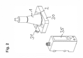
- FIG. 2 shows the test unit of the device for querying the condition of the sanding pad, ie whether a sanding pad 2 is accommodated there or not.
- the test unit consists of a test plate 30 which provides a compressed air supply 31 . Furthermore, a sensor 35 is arranged in the area of the testing device 30 . In this case, the sanding disc 1 is advanced onto the surface of the test plate 31 from above, so that the end face of the sanding disc 1 is deposited on the surface of the test plate 31 . The sanding disc 1 is then charged with compressed air via the compressed air supply 31 of the test plate. The pressure sensor can then be used to determine whether or not a sanding disc 2 is still adhering to the sanding disk 1 .
- FIG. 3a, 3b different representations of a storage magazine for storing a large number of abrasive flowers 2 are shown.
- the magazine consists essentially of a cylindrical container 40, which provides a total of three longitudinal grooves 41 in the axial direction on the outer circumference.
- Cantilevered brackets 42 are arranged in the area of these longitudinal grooves 41 and serve to accommodate suitable separating means.
- Brush elements whose brush holders 50 are mounted on the brackets 42 are used here as the separating means.
- the individual brush fibers 51 then extend through the grooves 41 into the cylindrical interior of the store 40, so that they can lie between abrasive blotches 2 stacked axially on top of one another as a separating means.
- these separating means 50, 51 are arranged rotationally symmetrically to the axial axis of the storage system, as a result of which a good separation between adjacent abrasive discs 2 is achieved.
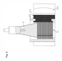
- the principle of separation becomes better in the sectional view of the figure 4 clarified.
- This shows an axial section through the storage system 40 with a large number of abrasive discs 2 stacked on top of one another in the axial direction.
- a corresponding separating means 50 with individual brush elements 51 can also be seen here.
- the individual brush elements 51 are passed through the groove 41 and are thus located between adjacent abrasive heads 2, so that they are separated from one another at least at the edges.
- the representation also shows the sanding disc 1 of the sanding system, which is inserted into the cylindrical storage container 40 from above in order to accommodate the uppermost sanding flower 2 via the Velcro connection.
Landscapes
- Engineering & Computer Science (AREA)
- Mechanical Engineering (AREA)
- Polishing Bodies And Polishing Tools (AREA)
- Finish Polishing, Edge Sharpening, And Grinding By Specific Grinding Devices (AREA)
Applications Claiming Priority (1)
| Application Number | Priority Date | Filing Date | Title |
|---|---|---|---|
| DE102020122115.0A DE102020122115B3 (de) | 2020-08-25 | 2020-08-25 | Vorrichtung und Verfahren zum Austausch einer Schleifscheibe oder Schleifblüte einer robotergestützten Schleifmaschine |
Publications (4)
| Publication Number | Publication Date |
|---|---|
| EP3964329A2 true EP3964329A2 (fr) | 2022-03-09 |
| EP3964329A3 EP3964329A3 (fr) | 2022-05-11 |
| EP3964329B1 EP3964329B1 (fr) | 2025-11-12 |
| EP3964329C0 EP3964329C0 (fr) | 2025-11-12 |
Family
ID=77300761
Family Applications (1)
| Application Number | Title | Priority Date | Filing Date |
|---|---|---|---|
| EP21190647.4A Active EP3964329B1 (fr) | 2020-08-25 | 2021-08-10 | Dispositif et procédé de remplacement d'un disque abrasif ou d'une roue abrasive d'une ponceuse robotisée |
Country Status (2)
| Country | Link |
|---|---|
| EP (1) | EP3964329B1 (fr) |
| DE (1) | DE102020122115B3 (fr) |
Citations (1)
| Publication number | Priority date | Publication date | Assignee | Title |
|---|---|---|---|---|
| EP2842689B1 (fr) | 2013-09-03 | 2015-07-08 | Asis Gmbh | Dispositif et procédé de remplacement d'une meule |
Family Cites Families (5)
| Publication number | Priority date | Publication date | Assignee | Title |
|---|---|---|---|---|
| FR2999107B1 (fr) * | 2012-12-10 | 2015-01-09 | Univ Nantes | Dispositif de poncage comprenant des moyens de changement de disque abrasif |
| CN110293475B (zh) | 2014-02-20 | 2022-04-05 | 菲比瑞卡马基纳莱有限公司 | 用于更换研磨机中的研磨片的设备 |
| CN105690243A (zh) | 2014-11-28 | 2016-06-22 | 富泰华工业(深圳)有限公司 | 自动抛光装置 |
| DE102017130801A1 (de) * | 2017-12-20 | 2019-06-27 | Rud. Starcke Gmbh & Co. Kg | Einrichtung zur Bereitstellung von Schleifblättern |
| WO2019123310A1 (fr) | 2017-12-20 | 2019-06-27 | Fabrica Machinale S.R.L. | Procédé et appareil permettant de réaliser le remplacement d'un élément abrasif dans une machine permettant d'usiner des surfaces |
-
2020
- 2020-08-25 DE DE102020122115.0A patent/DE102020122115B3/de active Active
-
2021
- 2021-08-10 EP EP21190647.4A patent/EP3964329B1/fr active Active
Patent Citations (1)
| Publication number | Priority date | Publication date | Assignee | Title |
|---|---|---|---|---|
| EP2842689B1 (fr) | 2013-09-03 | 2015-07-08 | Asis Gmbh | Dispositif et procédé de remplacement d'une meule |
Also Published As
| Publication number | Publication date |
|---|---|
| DE102020122115B3 (de) | 2022-02-24 |
| EP3964329A3 (fr) | 2022-05-11 |
| EP3964329B1 (fr) | 2025-11-12 |
| EP3964329C0 (fr) | 2025-11-12 |
Similar Documents
| Publication | Publication Date | Title |
|---|---|---|
| EP2842689B1 (fr) | Dispositif et procédé de remplacement d'une meule | |
| EP1736279A1 (fr) | Procédé et dispositif de production de verres optiques | |
| CH712094A1 (de) | Vorrichtung zum automatischen Wechsel von Schleifscheiben. | |
| DE3743979C1 (de) | Verfahren und Vorrichtung zum automatischen Ent- und Benadeln von Nadelbrettern | |
| DE2700502A1 (de) | Mehrstufenpresse | |
| DE1263565B (de) | Vorrichtung zum Herstellen von Filterzigaretten | |
| CH716376B1 (de) | Umrüstbare Greifvorrichtung. | |
| DE69110589T2 (de) | Verfahren und vorrichtung zum entfernen eines werkstückzuschnittes während einer elektroentladungsbearbeitung. | |
| DE1127305B (de) | Pressscheibe fuer Indirekt-Metallstrangpressen | |
| DE102020122115B3 (de) | Vorrichtung und Verfahren zum Austausch einer Schleifscheibe oder Schleifblüte einer robotergestützten Schleifmaschine | |
| DE202018004841U1 (de) | Packtulpe zum kopfseitigen Ergreifen von Flaschen | |
| DE102020122114A1 (de) | Vorrichtung zum automatischen Wechseln des Polierschwamms an einem Aufnahmeteller einer Poliermaschine | |
| WO2017076660A1 (fr) | Procédé d'appointissage mécanique de poils et dispositif de meulage | |
| DE4012314A1 (de) | Verfahren und vorrichtung zum reinigen eines werkzeughalters | |
| DE3527377C2 (fr) | ||
| DE102018122499A1 (de) | Einrichtung mit einem ersten und einem zweiten Roboter und Verfahren zu deren Betrieb | |
| DE102019134093A1 (de) | Wechselstation zum Ersetzen eines verbrauchten Arbeitsmittels durch ein unverbrauchtes Arbeitsmittel | |
| CH691442A5 (de) | Verfahren und Maschine zum Honen von Kleinstlöchern. | |
| DE3326292C1 (de) | Vorrichtung zum Wechseln des Sägeblattes an einer Kreissägemaschine | |
| DE2258398C3 (de) | Verfahren und Vorrichtung zum In-Verbindung-Bringen eines Linsenrohlings mit einem Linsenhalter und Zuführen des Linsenrohlings zur Bearbeitungsstation einer Maschine zum Schleifen und Polieren von Linsen | |
| DE102006041264A1 (de) | Elektrodenkappenfräs- und Wechseleinrichtung | |
| EP3941678A2 (fr) | Dispositif pour introduire un agent de séparation dans une pièce ouvrée creuse | |
| DE9317428U1 (de) | Schälvorrichtung für Industriewürste | |
| EP4377072B1 (fr) | Station de purge et procédé de purge | |
| DE102011015705A1 (de) | Radialpresse |
Legal Events
| Date | Code | Title | Description |
|---|---|---|---|
| PUAI | Public reference made under article 153(3) epc to a published international application that has entered the european phase |
Free format text: ORIGINAL CODE: 0009012 |
|
| STAA | Information on the status of an ep patent application or granted ep patent |
Free format text: STATUS: THE APPLICATION HAS BEEN PUBLISHED |
|
| AK | Designated contracting states |
Kind code of ref document: A2 Designated state(s): AL AT BE BG CH CY CZ DE DK EE ES FI FR GB GR HR HU IE IS IT LI LT LU LV MC MK MT NL NO PL PT RO RS SE SI SK SM TR |
|
| PUAL | Search report despatched |
Free format text: ORIGINAL CODE: 0009013 |
|
| AK | Designated contracting states |
Kind code of ref document: A3 Designated state(s): AL AT BE BG CH CY CZ DE DK EE ES FI FR GB GR HR HU IE IS IT LI LT LU LV MC MK MT NL NO PL PT RO RS SE SI SK SM TR |
|
| RIC1 | Information provided on ipc code assigned before grant |
Ipc: B24D 9/08 20060101ALI20220404BHEP Ipc: B24B 23/00 20060101AFI20220404BHEP |
|
| STAA | Information on the status of an ep patent application or granted ep patent |
Free format text: STATUS: REQUEST FOR EXAMINATION WAS MADE |
|
| 17P | Request for examination filed |
Effective date: 20221027 |
|
| GRAP | Despatch of communication of intention to grant a patent |
Free format text: ORIGINAL CODE: EPIDOSNIGR1 |
|
| STAA | Information on the status of an ep patent application or granted ep patent |
Free format text: STATUS: GRANT OF PATENT IS INTENDED |
|
| INTG | Intention to grant announced |
Effective date: 20250902 |
|
| GRAS | Grant fee paid |
Free format text: ORIGINAL CODE: EPIDOSNIGR3 |
|
| GRAA | (expected) grant |
Free format text: ORIGINAL CODE: 0009210 |
|
| STAA | Information on the status of an ep patent application or granted ep patent |
Free format text: STATUS: THE PATENT HAS BEEN GRANTED |
|
| AK | Designated contracting states |
Kind code of ref document: B1 Designated state(s): AL AT BE BG CH CY CZ DE DK EE ES FI FR GB GR HR HU IE IS IT LI LT LU LV MC MK MT NL NO PL PT RO RS SE SI SK SM TR |
|
| REG | Reference to a national code |
Ref country code: CH Ref legal event code: F10 Free format text: ST27 STATUS EVENT CODE: U-0-0-F10-F00 (AS PROVIDED BY THE NATIONAL OFFICE) Effective date: 20251112 Ref country code: GB Ref legal event code: FG4D Free format text: NOT ENGLISH |
|
| REG | Reference to a national code |
Ref country code: IE Ref legal event code: FG4D Free format text: LANGUAGE OF EP DOCUMENT: GERMAN |
|
| REG | Reference to a national code |
Ref country code: DE Ref legal event code: R096 Ref document number: 502021009175 Country of ref document: DE |
|
| U01 | Request for unitary effect filed |
Effective date: 20251124 |
|
| U07 | Unitary effect registered |
Designated state(s): AT BE BG DE DK EE FI FR IT LT LU LV MT NL PT RO SE SI Effective date: 20251203 |
|
| REG | Reference to a national code |
Ref country code: SK Ref legal event code: T3 Ref document number: E 47619 Country of ref document: SK |
|
| PG25 | Lapsed in a contracting state [announced via postgrant information from national office to epo] |
Ref country code: ES Free format text: LAPSE BECAUSE OF FAILURE TO SUBMIT A TRANSLATION OF THE DESCRIPTION OR TO PAY THE FEE WITHIN THE PRESCRIBED TIME-LIMIT Effective date: 20251112 |
|
| PG25 | Lapsed in a contracting state [announced via postgrant information from national office to epo] |
Ref country code: NO Free format text: LAPSE BECAUSE OF FAILURE TO SUBMIT A TRANSLATION OF THE DESCRIPTION OR TO PAY THE FEE WITHIN THE PRESCRIBED TIME-LIMIT Effective date: 20260212 |
|
| PG25 | Lapsed in a contracting state [announced via postgrant information from national office to epo] |
Ref country code: HR Free format text: LAPSE BECAUSE OF FAILURE TO SUBMIT A TRANSLATION OF THE DESCRIPTION OR TO PAY THE FEE WITHIN THE PRESCRIBED TIME-LIMIT Effective date: 20251112 |
|
| PG25 | Lapsed in a contracting state [announced via postgrant information from national office to epo] |
Ref country code: RS Free format text: LAPSE BECAUSE OF FAILURE TO SUBMIT A TRANSLATION OF THE DESCRIPTION OR TO PAY THE FEE WITHIN THE PRESCRIBED TIME-LIMIT Effective date: 20260212 |
|
| PG25 | Lapsed in a contracting state [announced via postgrant information from national office to epo] |
Ref country code: IS Free format text: LAPSE BECAUSE OF FAILURE TO SUBMIT A TRANSLATION OF THE DESCRIPTION OR TO PAY THE FEE WITHIN THE PRESCRIBED TIME-LIMIT Effective date: 20260312 |
|
| PG25 | Lapsed in a contracting state [announced via postgrant information from national office to epo] |
Ref country code: PL Free format text: LAPSE BECAUSE OF FAILURE TO SUBMIT A TRANSLATION OF THE DESCRIPTION OR TO PAY THE FEE WITHIN THE PRESCRIBED TIME-LIMIT Effective date: 20251112 |