EP3964423B1 - Chariot permettant de recevoir au moins un récipient de transport - Google Patents
Chariot permettant de recevoir au moins un récipient de transport Download PDFInfo
- Publication number
- EP3964423B1 EP3964423B1 EP21187692.5A EP21187692A EP3964423B1 EP 3964423 B1 EP3964423 B1 EP 3964423B1 EP 21187692 A EP21187692 A EP 21187692A EP 3964423 B1 EP3964423 B1 EP 3964423B1
- Authority
- EP
- European Patent Office
- Prior art keywords
- trolley
- trolley according
- baseplate
- trough
- stacking
- Prior art date
- Legal status (The legal status is an assumption and is not a legal conclusion. Google has not performed a legal analysis and makes no representation as to the accuracy of the status listed.)
- Active
Links
Images


Classifications
-
- B—PERFORMING OPERATIONS; TRANSPORTING
- B62—LAND VEHICLES FOR TRAVELLING OTHERWISE THAN ON RAILS
- B62B—HAND-PROPELLED VEHICLES, e.g. HAND CARTS OR PERAMBULATORS; SLEDGES
- B62B5/00—Accessories or details specially adapted for hand carts
- B62B5/0083—Wheeled supports connected to the transported object
- B62B5/0093—Flat dollys without hand moving equipment
-
- B—PERFORMING OPERATIONS; TRANSPORTING
- B62—LAND VEHICLES FOR TRAVELLING OTHERWISE THAN ON RAILS
- B62B—HAND-PROPELLED VEHICLES, e.g. HAND CARTS OR PERAMBULATORS; SLEDGES
- B62B3/00—Hand carts having more than one axis carrying transport wheels; Steering devices therefor; Equipment therefor
- B62B3/008—Hand carts having more than one axis carrying transport wheels; Steering devices therefor; Equipment therefor having more than two axes
-
- B—PERFORMING OPERATIONS; TRANSPORTING
- B62—LAND VEHICLES FOR TRAVELLING OTHERWISE THAN ON RAILS
- B62B—HAND-PROPELLED VEHICLES, e.g. HAND CARTS OR PERAMBULATORS; SLEDGES
- B62B3/00—Hand carts having more than one axis carrying transport wheels; Steering devices therefor; Equipment therefor
- B62B3/14—Hand carts having more than one axis carrying transport wheels; Steering devices therefor; Equipment therefor characterised by provisions for nesting or stacking, e.g. shopping trolleys
- B62B3/16—Hand carts having more than one axis carrying transport wheels; Steering devices therefor; Equipment therefor characterised by provisions for nesting or stacking, e.g. shopping trolleys vertically stackable
-
- B—PERFORMING OPERATIONS; TRANSPORTING
- B62—LAND VEHICLES FOR TRAVELLING OTHERWISE THAN ON RAILS
- B62B—HAND-PROPELLED VEHICLES, e.g. HAND CARTS OR PERAMBULATORS; SLEDGES
- B62B2202/00—Indexing codes relating to type or characteristics of transported articles
- B62B2202/12—Boxes, Crates
-
- B—PERFORMING OPERATIONS; TRANSPORTING
- B62—LAND VEHICLES FOR TRAVELLING OTHERWISE THAN ON RAILS
- B62B—HAND-PROPELLED VEHICLES, e.g. HAND CARTS OR PERAMBULATORS; SLEDGES
- B62B2501/00—Manufacturing; Constructional features
- B62B2501/04—Production features
-
- B—PERFORMING OPERATIONS; TRANSPORTING
- B62—LAND VEHICLES FOR TRAVELLING OTHERWISE THAN ON RAILS
- B62B—HAND-PROPELLED VEHICLES, e.g. HAND CARTS OR PERAMBULATORS; SLEDGES
- B62B2501/00—Manufacturing; Constructional features
- B62B2501/06—Materials used
- B62B2501/065—Plastics
Definitions
- the invention relates to a trolley, in particular a transport trolley for receiving one or more transport containers, with a base plate made of plastic, also with a number of rollers connected to the underside of the base plate, and with at least one stacking trough on the upper side for receiving at least one roller of another trolley placed on the upper side of the base plate, the stacking trough having at least one drainage opening.
- Such trolleys are used in logistics and in particular in the food industry. With their help, goods are typically shipped between wholesalers and retailers.
- Collapsible transport containers for example, can be placed on the top of the base plate. The transport containers in turn serve to hold food but also machine parts.
- Such transport containers are, for example, in the WO 00/68099 A1 described.
- the collapsible transport containers can be reused.
- the trolleys So that these can be collected and transported as compactly as possible, the trolleys are stacked on top of each other. This allows columns to be formed by several trolleys. For this purpose, the respective roller of a trolley engages in the stacking trough of the further trolley located underneath it.
- Such trolleys are known from practice in a variety of designs.
- the well-known trolleys have basically proven themselves, but still offer room for improvement.
- trolleys with, for example, four rollers connected to the underside of the base plate
- butcher's trolleys or trolleys for use in butcher's shops or in connection with the transport of meat, meat waste, etc.
- the at least three pairs of rollers realized at this point are typically designed as fixed rollers. This makes it possible to use the middle fixed castors as a kind of axis of rotation, so that such trolleys can be turned on the spot by practically any angle, in particular by 180° or even 360°. This has basically worked.
- JP 2000177594A When generic and insofar closest prior art according to JP 2000177594A is about a trolley, which is already equipped with two opposing drainage openings in a stacking trough.
- the stacking trough in question of a trolley underneath logically takes up the roll of the trolley in question, so that the roll can be wetted with moisture as a result.
- JP H09 86415 A relates to a roll container that relies on a continuous longitudinal recess as a stacking trough for stackability. Additional drainage openings are not provided.
- the invention is based on the technical problem of further developing such a trolley and in particular a transport trolley for receiving one or more transport containers in such a way that the strict hygiene requirements, particularly in the food sector, are met and permanent soiling is avoided.
- the invention according to claim 1 proposes, in the case of a generic trolley and in particular a transport trolley for receiving one or more transport containers, that the stacking trough be designed as a longitudinal depression running over almost the entire broad side of the base plate, the stacking trough being equipped with two drainage openings arranged on both sides of a support surface.
- the stacking trough on the top or the several stacking troughs has two drainage openings in each case on the upper side of the base plate. These drainage openings usually open towards the underside of the base plate, so that any accumulation of liquid and water inside the stacking trough is reliably avoided from the outset and according to the invention.
- the stacking trough is designed according to the invention as a longitudinal depression running over almost the entire broad side of the base plate.
- the invention is initially based on the knowledge that the base plate and consequently the trolley is typically rectangular.
- a trolley usually has the dimensions 400 mm x 600 mm, i.e. the size is adapted to a so-called half pallet or corresponds to it.
- the rollers are each arranged on the underside of the broad side of the base plate.
- the invention does not work now back to separate stacking troughs for each individual roll on the broad side of the base plate in question. Rather, a practically continuous stacking trough is provided and realized in the form of the longitudinal depression running almost over the entire broad side of the base plate.
- all of the rollers arranged along this broad side of the base plate are arranged in the stacking trough, which is designed as a longitudinal depression running across the entire broad side of the base plate, of a trolley located underneath.
- the stacking trough in question is equipped with two drainage openings.
- the design is such that the two drainage openings are arranged on both sides of the support surface, preferably for a central roller.
- the stacking trough advantageously has at least one gradient in the direction of the drainage openings or in the direction of the respective drainage opening.
- inclines are provided so that, starting from the support surface, any water present on or in the support surface is reliably drained away, for example on both sides of the support surface, in the direction of the associated drainage opening.
- the invention is also based on the knowledge that generally at least three pairs of rollers are connected to the underside of the base plate.
- the three pairs of rollers are all designed as fixed rollers.
- the procedure is such that the central fixed castors have a greater distance between their associated running surface and the underside of the base plate than the two lateral fixed castors.
- the design is such that the central fixed castors are each supported on the support surface of the stacking trough of a trolley located underneath when stacked.
- the lateral fixed rollers are supported within the stacking trough on further support surfaces or additionally provided trough surfaces within the stacking trough or the longitudinal recess realized at this point and running in the longitudinal direction.
- the longitudinal recess in question has at least one trough surface or is also equipped with at least two trough surfaces in order to provide proper positioning of all the rollers within the longitudinal recess when the trolleys are stacked.
- the design is such that the trough surface within the longitudinal depression also communicates with a slope that runs in the direction of an associated drainage opening, so that any standing or remaining water in the region of the trough surface after a cleaning process, for example, is properly drained via the slope and then the drainage opening or the several drainage openings.
- the bottom plate is advantageously closed on the underside with the aid of a bottom plate.
- the floor panel and the underbody panel are usually welded together.
- the invention proposes that the two plates be joined together by a so-called butt welding process.
- the procedure is such that the two panels to be connected, ie the floor panel and the underbody panel, are placed on both sides against a heated mirror that is inserted between them. This melts at least the edges of the two panels to be joined, so that after removing the mirror, the two plates can be combined with one another as desired.
- the floor panel is designed as a plastic injection molded part.
- Typical thermoplastics such as PE (polyethylene) or PP (polypropylene) as well as PA (polyamide) can be used.
- PE polyethylene
- PP polypropylene
- PA polyamide
- Mixed forms are also conceivable. It is also possible to reinforce the plastic with embedded fibers, in particular glass fibers.
- the trolley according to the invention is also and particularly suitable for transporting heavy foodstuffs such as transport containers that are filled with meat.
- Such trolleys for the butcher's shop or butcher's shops are usually moved in such a way that the middle pair of rollers and one of the two lateral pairs of rollers together provide a rolling support.
- the other pair of rollers on the side remain “in the air” because the greater distance between the running surface of the central fixed rollers and the underside of the base plate ensures that the trolley is "tipped" to one side or the other during this process.
- This procedure has the further advantage that the trolley can be turned practically on the spot despite the fixed castors implemented at this point, in that the middle fixed castors describe a circle.
- the trolley in question is not only stable, but also designed to be particularly functional.
- the trolley according to the invention is predestined for applications in the food industry and for additional regular cleaning.
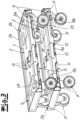
- a trolley is shown in the figures, which is a transport trolley for receiving one or more transport containers.
- the transport containers are placed on top 1 of a base plate 2 made of plastic.
- the base plate 2 made of plastic is equipped with a peripheral edge 2a with drainage openings 2b at the corners.
- the upper side 1 of the base plate 2 is made of plastic with a smooth surface, apart from a number of openings 3, 4.
- These openings 3, 4 are openings for weight reduction on the one hand and openings for gripping 4 on the other hand, which operating personnel can use can manipulate the trolley, for example in a stacking arrangement as shown in FIG 1 able to transfer.
- the bottom plate 2 made of plastic is also equipped with an underside 5.
- the underside 5 is formed by an underbody panel 5 .
- the underbody panel 5 is welded to the floor panel 2, according to the exemplary embodiment connected tightly to the floor panel 2 by a butt welding process of the two panels 2, 5.
- the underbody plate 5 is also smooth overall and only has the previously mentioned openings 3, 4, which continue from the top 1 of the base plate 2 to the underside or the underbody plate 5. This not only saves weight, but also ensures that any water remaining on the upper side 1 of the base plate 2 during the cleaning process can drain off via the openings 3, 4 in question. This also applies to the corner-side drainage openings 2b in the peripheral edge 2a.
- the base plate 2 is used with its upper side 1 to accommodate one or more transport containers, not shown in detail.
- These transport containers may be cargo containers that can be folded and erected, as in the WO 00/68099 A1 is described in detail.
- further fixing stops 6 are provided on the upper side 1 of the base plate 2 for the transport container in question, but these can in principle also be omitted.
- the trolley shown is equipped with several rollers 7, 8 connected to the bottom plate 2 on the underside. actually become the rollers 7, 8 set according to the embodiment on the underbody panel 5, with, for example, screws that pass through the underbody panel 5 and engage in not shown mounting domes as part of a ribbing of the floor panel 2.
- the rollers 7, 8 are, in the exemplary embodiment and not restrictively, consistently fixed rollers, ie rollers that are rigid and do not allow any steering or rotary movements.
- a total of three pairs of rollers 7, 8 are realized according to the embodiment.
- the middle pair of rollers or the middle fixed rollers 8 are equipped with a greater distance A of their running surface from the underside 5 or the underbody plate 5 of the base plate 2 compared to the two lateral fixed rollers 7.
- FIG 1 clearly.
- the loaded trolley is transported for the purpose of transport either using the two front fixed rollers 7 and the middle fixed rollers 8 or alternatively using the rear fixed rollers 7 and the middle fixed rollers 8.
- the change between these two transport positions corresponds to a "tipping movement" of the trolley about the two central fixed rollers 8. This also gives the possibility that the trolley can be rotated on the spot about the two central fixed rollers 8.
- the trolley also has two upper stacking troughs 9 which, according to the exemplary embodiment and according to the invention, are each designed as longitudinal depressions running over almost the entire broad side of the base plate 2 .
- the respective stacking trough 9 has two drainage openings 10.
- the base plate 2 and therefore the entire trolley is rectangular, with the broad side coinciding with the long side and consequently with that side of the base plate 2 along which the two stacking troughs 9 each extend at the edge.
- the rollers 7, 8 of an attached trolley can be accommodated in the stacking troughs 9.
- the stacking trough 9 has two drainage openings 10.
- two drainage openings 10 are realized, which are arranged on both sides of a support surface 9a.
- the support surface 9a serves to support the middle fixed rollers 8 of the additional trolley placed in the stacked state.
- two additionally provided trough surfaces 9b are realized at the ends of the stacking trough 9, which receive the lateral fixed rollers 7.
- the two trough surfaces 9b are raised towards the respective edge of the base plate 2 or towards its narrow side, so that the fixed castor 7 of the remote trolley accommodated therein is centered in the axial direction or longitudinal direction.
- the design is such that the stacking trough 9 has a slope 11 , 12 in the direction of the respective drainage opening 10 .
- two end slopes 11 are realized at the end of the respective trough surface 9b and, in addition, two end slopes 12 each end of the central support surface 9a.
- the individual trough surfaces 9b as well as the central support surface 9a are properly drained in the direction of the drainage openings 10, so that overall no water and thus no dirt can accumulate in the stacking trough 9 according to the invention.
- the trough surface 9b is also equipped with a lateral stop 13, so that in connection with the edge of the trough surface 9b raised in the direction of the narrow side of the base plate 2, the roller 7 accommodated therein is secured not only in the axial direction or longitudinal direction, but also perpendicular thereto in the direction of the narrow side of the base plate 2 (transverse direction).
- This allows a proper stack to be produced from the individual trolleys, in that the individual rollers 7, 8 each nestingly engage in the stacking trough 9 of the trolley below.
Landscapes
- Engineering & Computer Science (AREA)
- Chemical & Material Sciences (AREA)
- Combustion & Propulsion (AREA)
- Transportation (AREA)
- Mechanical Engineering (AREA)
- Handcart (AREA)
Claims (13)
- Chariot, notamment chariot de transport, destiné à recevoir un ou plusieurs conteneurs de transport, pourvu d'une plaque de fond (2) en matière plastique, pourvu par ailleurs de plusieurs roulettes (7, 8) raccordées sur la face inférieure de la plaque de fond (2) et pourvu sur sa face supérieure d'au moins une cavité d'empilage (9), destinée à recevoir au moins une roulette (7, 8) d'un autre chariot placé sur la face supérieure de la plaque de fond (2), la cavité d'empilage (9) comportant au moins un orifice de drainage (10),
caractérisé en ce quela cavité d'empilage (9) est conçue sous la forme d'un creux longitudinal s'écoulant sur pratiquement tout le côté largeur de la plaque de fond (2) lacavitéd'empilage (9) étant équipée de deux orifices de drainage (10) placés de part et d'autre d'une surface d'appui (9a). - Chariot selon la revendication 1, caractérisé en ce que la surface d'appui (9a) sert pour une roulette (8) centrale.
- Chariot selon l'une quelconque des revendications 1 ou 2, caractérisé en ce que la cavité d'empilage (9) comporte en direction de l'orifice de drainage (10) au moins une déclivité (11, 12).
- Chariot selon la revendication 3, caractérisé en ce que plusieurs déclivités (11, 12) sont prévues.
- Chariot selon l'une quelconque des revendications 1 à 4, caractérisé en ce que la plaque de fond (2) est fermée sur sa face supérieure à l'aide d'une plaque de sous-plancher (5).
- Chariot selon la revendication 5, caractérisé en ce que la plaque de fond (2) et la plaque de sous-plancher (5) sont soudées l'une à l'autre.
- Chariot selon la revendication 6, caractérisé en ce que les deux plaques (2, 5) sont réunies l'une à l'autre par un procédé de soudage au miroir.
- Chariot selon l'une quelconque des revendications 1 à 7, caractérisé en ce qu'un total d'au moins trois paires (7, 8) de roulettes sont raccordées sur la face inférieure de la plaque de fond (2).
- Chariot selon la revendication 8, caractérisé en ce que le trois paires (7, 8) de roulettes sont toutes conçues sous la forme de roulettes fixes.
- Chariot selon la revendication 8 ou 9, caractérisé en ce que les roulettes (8) fixes centrales présentent un écart (A) entre leur surface de roulement et la face inférieure (5) de la plaque de fond (2) qui est supérieur à celui des deux roulettes (7) fixes latérales.
- Chariot selon l'une quelconque des revendications 8 à 10, caractérisé en ce que les roulettes (8) fixes centrales s'appuient chacune sur la surface d'appui (9a) de la cavité d'empilage (9).
- Chariot selon l'une quelconque des revendications 1 à 11, caractérisé en ce que la plaque de fond (2) comporte sur sa face supérieure (1) un bord périphérique (2a) en tant que butée de fixation pour le / les conteneurs de transport.
- Chariot selon la revendication 12, caractérisé en ce que le bord périphérique (2a) est équipé sur ses angles d'orifices de drainage (2b).
Applications Claiming Priority (1)
| Application Number | Priority Date | Filing Date | Title |
|---|---|---|---|
| DE202020105166.0U DE202020105166U1 (de) | 2020-09-08 | 2020-09-08 | Rollwagen, insbesondere Transportrollwagen zur Aufnahme eines oder mehrerer Transportbehälter |
Publications (2)
| Publication Number | Publication Date |
|---|---|
| EP3964423A1 EP3964423A1 (fr) | 2022-03-09 |
| EP3964423B1 true EP3964423B1 (fr) | 2023-07-26 |
Family
ID=72660262
Family Applications (1)
| Application Number | Title | Priority Date | Filing Date |
|---|---|---|---|
| EP21187692.5A Active EP3964423B1 (fr) | 2020-09-08 | 2021-07-26 | Chariot permettant de recevoir au moins un récipient de transport |
Country Status (2)
| Country | Link |
|---|---|
| EP (1) | EP3964423B1 (fr) |
| DE (1) | DE202020105166U1 (fr) |
Families Citing this family (2)
| Publication number | Priority date | Publication date | Assignee | Title |
|---|---|---|---|---|
| CN117208057B (zh) * | 2023-08-07 | 2025-10-28 | 中集车辆(山东)有限公司 | 一种可调节的工具车用连接结构 |
| CN120482529B (zh) * | 2025-07-18 | 2025-09-19 | 沈阳新河电缆有限公司 | 一种便于建筑工地倾卸的成捆电缆运输装置 |
Family Cites Families (8)
| Publication number | Priority date | Publication date | Assignee | Title |
|---|---|---|---|---|
| DK169911B1 (da) | 1992-12-22 | 1995-04-03 | Rd Impex Aps | Rullevogn med svingbare hjul |
| DE9413355U1 (de) * | 1994-08-18 | 1994-10-20 | Völkl, Thomas, 83052 Bruckmühl | Stapelbarer Rolli, insbesondere für die Lebensmittelindustrie |
| JPH0986415A (ja) * | 1995-09-22 | 1997-03-31 | Motohiro Seisakusho:Kk | 運搬台車 |
| JP4216385B2 (ja) * | 1998-12-17 | 2009-01-28 | 成臣 山田 | 運搬台車 |
| NL1012013C2 (nl) | 1999-05-10 | 2000-11-13 | Wavin Trepak B V | Houder met vergrendelbare zijwanden. |
| EP1762456A1 (fr) | 2005-09-08 | 2007-03-14 | Werner Feil GmbH | Châssis de transport, en particulier un haquet |
| EP3546315A1 (fr) * | 2018-03-26 | 2019-10-02 | FEIL GmbH | Palette roulante |
| CN208881875U (zh) | 2018-08-31 | 2019-05-21 | K·哈特瓦尔有限公司 | 小推车 |
-
2020
- 2020-09-08 DE DE202020105166.0U patent/DE202020105166U1/de active Active
-
2021
- 2021-07-26 EP EP21187692.5A patent/EP3964423B1/fr active Active
Also Published As
| Publication number | Publication date |
|---|---|
| DE202020105166U1 (de) | 2020-09-16 |
| EP3964423A1 (fr) | 2022-03-09 |
Similar Documents
| Publication | Publication Date | Title |
|---|---|---|
| EP3636559B1 (fr) | Boîte empilable | |
| EP3964423B1 (fr) | Chariot permettant de recevoir au moins un récipient de transport | |
| WO2007137774A1 (fr) | Système de caisses en particulier pour le transport de poissons frais | |
| EP3290347B1 (fr) | Dispositif de transport de pièces | |
| DE4312842C2 (de) | Einstückig aus Kunststoff hergestellte Transportmittel, insbesondere Transportkästen, Tablare, Paletten o. dgl. | |
| EP2014535B1 (fr) | Conteneur sur rouleaux empilable | |
| DE102007033147B4 (de) | Stapelbarer Rollbehälter | |
| EP0496990B1 (fr) | Ensemble de ramassage de déchets | |
| CH686360A5 (de) | Lager- und Transportbehaelter aus Kunststoff. | |
| EP4482752A1 (fr) | Cadre de support de pièce et système de cadre de support de pièce | |
| DE10054306C1 (de) | Rollwagen | |
| DE202013100968U1 (de) | Palettenbox | |
| EP3626646B1 (fr) | Boîte empilable | |
| DE20315302U1 (de) | Einstückig durch Verschweißen hergestellter Behälter aus Kunststoff | |
| DE9314468U1 (de) | Palette aus zwei gleichen Teilen | |
| EP1669214B1 (fr) | Plateau de stockage | |
| DE3026345C2 (de) | Beschickungswagen für Güter der Fleischwarenindustrie | |
| DE8914062U1 (de) | Lager- und Transportkasten aus Blech | |
| DE9215975U1 (de) | Mit einem Deckel verschließbarer kubischer Transportbehälter | |
| EP0789660A1 (fr) | Caisse de transport | |
| DE9301983U1 (de) | Insbesondere im Bauwesen zu verwendender Behälter zur Aufnahme irgend welcher Materialien, Gerätschaften usw. | |
| EP0606073A2 (fr) | Casier à bouteilles | |
| EP1529733A1 (fr) | Plateau à roues | |
| DE9406465U1 (de) | Kasten für Flaschen oder ähnliche Behältnisse | |
| DE9417452U1 (de) | Transportkasten |
Legal Events
| Date | Code | Title | Description |
|---|---|---|---|
| PUAI | Public reference made under article 153(3) epc to a published international application that has entered the european phase |
Free format text: ORIGINAL CODE: 0009012 |
|
| STAA | Information on the status of an ep patent application or granted ep patent |
Free format text: STATUS: THE APPLICATION HAS BEEN PUBLISHED |
|
| AK | Designated contracting states |
Kind code of ref document: A1 Designated state(s): AL AT BE BG CH CY CZ DE DK EE ES FI FR GB GR HR HU IE IS IT LI LT LU LV MC MK MT NL NO PL PT RO RS SE SI SK SM TR |
|
| STAA | Information on the status of an ep patent application or granted ep patent |
Free format text: STATUS: REQUEST FOR EXAMINATION WAS MADE |
|
| 17P | Request for examination filed |
Effective date: 20220505 |
|
| RBV | Designated contracting states (corrected) |
Designated state(s): AL AT BE BG CH CY CZ DE DK EE ES FI FR GB GR HR HU IE IS IT LI LT LU LV MC MK MT NL NO PL PT RO RS SE SI SK SM TR |
|
| GRAP | Despatch of communication of intention to grant a patent |
Free format text: ORIGINAL CODE: EPIDOSNIGR1 |
|
| STAA | Information on the status of an ep patent application or granted ep patent |
Free format text: STATUS: GRANT OF PATENT IS INTENDED |
|
| GRAS | Grant fee paid |
Free format text: ORIGINAL CODE: EPIDOSNIGR3 |
|
| INTG | Intention to grant announced |
Effective date: 20230425 |
|
| GRAA | (expected) grant |
Free format text: ORIGINAL CODE: 0009210 |
|
| STAA | Information on the status of an ep patent application or granted ep patent |
Free format text: STATUS: THE PATENT HAS BEEN GRANTED |
|
| AK | Designated contracting states |
Kind code of ref document: B1 Designated state(s): AL AT BE BG CH CY CZ DE DK EE ES FI FR GB GR HR HU IE IS IT LI LT LU LV MC MK MT NL NO PL PT RO RS SE SI SK SM TR |
|
| REG | Reference to a national code |
Ref country code: CH Ref legal event code: EP |
|
| REG | Reference to a national code |
Ref country code: IE Ref legal event code: FG4D Free format text: LANGUAGE OF EP DOCUMENT: GERMAN |
|
| REG | Reference to a national code |
Ref country code: DE Ref legal event code: R096 Ref document number: 502021001075 Country of ref document: DE |
|
| REG | Reference to a national code |
Ref country code: LT Ref legal event code: MG9D |
|
| REG | Reference to a national code |
Ref country code: NL Ref legal event code: MP Effective date: 20230726 |
|
| PG25 | Lapsed in a contracting state [announced via postgrant information from national office to epo] |
Ref country code: NL Free format text: LAPSE BECAUSE OF FAILURE TO SUBMIT A TRANSLATION OF THE DESCRIPTION OR TO PAY THE FEE WITHIN THE PRESCRIBED TIME-LIMIT Effective date: 20230726 |
|
| PG25 | Lapsed in a contracting state [announced via postgrant information from national office to epo] |
Ref country code: GR Free format text: LAPSE BECAUSE OF FAILURE TO SUBMIT A TRANSLATION OF THE DESCRIPTION OR TO PAY THE FEE WITHIN THE PRESCRIBED TIME-LIMIT Effective date: 20231027 |
|
| PG25 | Lapsed in a contracting state [announced via postgrant information from national office to epo] |
Ref country code: IS Free format text: LAPSE BECAUSE OF FAILURE TO SUBMIT A TRANSLATION OF THE DESCRIPTION OR TO PAY THE FEE WITHIN THE PRESCRIBED TIME-LIMIT Effective date: 20231126 |
|
| PG25 | Lapsed in a contracting state [announced via postgrant information from national office to epo] |
Ref country code: SE Free format text: LAPSE BECAUSE OF FAILURE TO SUBMIT A TRANSLATION OF THE DESCRIPTION OR TO PAY THE FEE WITHIN THE PRESCRIBED TIME-LIMIT Effective date: 20230726 Ref country code: RS Free format text: LAPSE BECAUSE OF FAILURE TO SUBMIT A TRANSLATION OF THE DESCRIPTION OR TO PAY THE FEE WITHIN THE PRESCRIBED TIME-LIMIT Effective date: 20230726 Ref country code: PT Free format text: LAPSE BECAUSE OF FAILURE TO SUBMIT A TRANSLATION OF THE DESCRIPTION OR TO PAY THE FEE WITHIN THE PRESCRIBED TIME-LIMIT Effective date: 20231127 Ref country code: NO Free format text: LAPSE BECAUSE OF FAILURE TO SUBMIT A TRANSLATION OF THE DESCRIPTION OR TO PAY THE FEE WITHIN THE PRESCRIBED TIME-LIMIT Effective date: 20231026 Ref country code: LV Free format text: LAPSE BECAUSE OF FAILURE TO SUBMIT A TRANSLATION OF THE DESCRIPTION OR TO PAY THE FEE WITHIN THE PRESCRIBED TIME-LIMIT Effective date: 20230726 Ref country code: LT Free format text: LAPSE BECAUSE OF FAILURE TO SUBMIT A TRANSLATION OF THE DESCRIPTION OR TO PAY THE FEE WITHIN THE PRESCRIBED TIME-LIMIT Effective date: 20230726 Ref country code: IS Free format text: LAPSE BECAUSE OF FAILURE TO SUBMIT A TRANSLATION OF THE DESCRIPTION OR TO PAY THE FEE WITHIN THE PRESCRIBED TIME-LIMIT Effective date: 20231126 Ref country code: HR Free format text: LAPSE BECAUSE OF FAILURE TO SUBMIT A TRANSLATION OF THE DESCRIPTION OR TO PAY THE FEE WITHIN THE PRESCRIBED TIME-LIMIT Effective date: 20230726 Ref country code: GR Free format text: LAPSE BECAUSE OF FAILURE TO SUBMIT A TRANSLATION OF THE DESCRIPTION OR TO PAY THE FEE WITHIN THE PRESCRIBED TIME-LIMIT Effective date: 20231027 Ref country code: FI Free format text: LAPSE BECAUSE OF FAILURE TO SUBMIT A TRANSLATION OF THE DESCRIPTION OR TO PAY THE FEE WITHIN THE PRESCRIBED TIME-LIMIT Effective date: 20230726 |
|
| PG25 | Lapsed in a contracting state [announced via postgrant information from national office to epo] |
Ref country code: PL Free format text: LAPSE BECAUSE OF FAILURE TO SUBMIT A TRANSLATION OF THE DESCRIPTION OR TO PAY THE FEE WITHIN THE PRESCRIBED TIME-LIMIT Effective date: 20230726 |
|
| REG | Reference to a national code |
Ref country code: BE Ref legal event code: MM Effective date: 20230731 |
|
| PG25 | Lapsed in a contracting state [announced via postgrant information from national office to epo] |
Ref country code: LU Free format text: LAPSE BECAUSE OF NON-PAYMENT OF DUE FEES Effective date: 20230726 |
|
| PG25 | Lapsed in a contracting state [announced via postgrant information from national office to epo] |
Ref country code: LU Free format text: LAPSE BECAUSE OF NON-PAYMENT OF DUE FEES Effective date: 20230726 |
|
| REG | Reference to a national code |
Ref country code: IE Ref legal event code: MM4A |
|
| PG25 | Lapsed in a contracting state [announced via postgrant information from national office to epo] |
Ref country code: ES Free format text: LAPSE BECAUSE OF FAILURE TO SUBMIT A TRANSLATION OF THE DESCRIPTION OR TO PAY THE FEE WITHIN THE PRESCRIBED TIME-LIMIT Effective date: 20230726 |
|
| REG | Reference to a national code |
Ref country code: DE Ref legal event code: R097 Ref document number: 502021001075 Country of ref document: DE |
|
| PG25 | Lapsed in a contracting state [announced via postgrant information from national office to epo] |
Ref country code: SM Free format text: LAPSE BECAUSE OF FAILURE TO SUBMIT A TRANSLATION OF THE DESCRIPTION OR TO PAY THE FEE WITHIN THE PRESCRIBED TIME-LIMIT Effective date: 20230726 Ref country code: RO Free format text: LAPSE BECAUSE OF FAILURE TO SUBMIT A TRANSLATION OF THE DESCRIPTION OR TO PAY THE FEE WITHIN THE PRESCRIBED TIME-LIMIT Effective date: 20230726 Ref country code: ES Free format text: LAPSE BECAUSE OF FAILURE TO SUBMIT A TRANSLATION OF THE DESCRIPTION OR TO PAY THE FEE WITHIN THE PRESCRIBED TIME-LIMIT Effective date: 20230726 Ref country code: EE Free format text: LAPSE BECAUSE OF FAILURE TO SUBMIT A TRANSLATION OF THE DESCRIPTION OR TO PAY THE FEE WITHIN THE PRESCRIBED TIME-LIMIT Effective date: 20230726 Ref country code: DK Free format text: LAPSE BECAUSE OF FAILURE TO SUBMIT A TRANSLATION OF THE DESCRIPTION OR TO PAY THE FEE WITHIN THE PRESCRIBED TIME-LIMIT Effective date: 20230726 Ref country code: CZ Free format text: LAPSE BECAUSE OF FAILURE TO SUBMIT A TRANSLATION OF THE DESCRIPTION OR TO PAY THE FEE WITHIN THE PRESCRIBED TIME-LIMIT Effective date: 20230726 Ref country code: SK Free format text: LAPSE BECAUSE OF FAILURE TO SUBMIT A TRANSLATION OF THE DESCRIPTION OR TO PAY THE FEE WITHIN THE PRESCRIBED TIME-LIMIT Effective date: 20230726 Ref country code: MC Free format text: LAPSE BECAUSE OF FAILURE TO SUBMIT A TRANSLATION OF THE DESCRIPTION OR TO PAY THE FEE WITHIN THE PRESCRIBED TIME-LIMIT Effective date: 20230726 |
|
| PG25 | Lapsed in a contracting state [announced via postgrant information from national office to epo] |
Ref country code: IT Free format text: LAPSE BECAUSE OF FAILURE TO SUBMIT A TRANSLATION OF THE DESCRIPTION OR TO PAY THE FEE WITHIN THE PRESCRIBED TIME-LIMIT Effective date: 20230726 Ref country code: BE Free format text: LAPSE BECAUSE OF NON-PAYMENT OF DUE FEES Effective date: 20230731 |
|
| PLBE | No opposition filed within time limit |
Free format text: ORIGINAL CODE: 0009261 |
|
| STAA | Information on the status of an ep patent application or granted ep patent |
Free format text: STATUS: NO OPPOSITION FILED WITHIN TIME LIMIT |
|
| 26N | No opposition filed |
Effective date: 20240429 |
|
| PG25 | Lapsed in a contracting state [announced via postgrant information from national office to epo] |
Ref country code: IE Free format text: LAPSE BECAUSE OF NON-PAYMENT OF DUE FEES Effective date: 20230726 |
|
| PG25 | Lapsed in a contracting state [announced via postgrant information from national office to epo] |
Ref country code: IE Free format text: LAPSE BECAUSE OF NON-PAYMENT OF DUE FEES Effective date: 20230726 Ref country code: FR Free format text: LAPSE BECAUSE OF NON-PAYMENT OF DUE FEES Effective date: 20230926 Ref country code: SI Free format text: LAPSE BECAUSE OF FAILURE TO SUBMIT A TRANSLATION OF THE DESCRIPTION OR TO PAY THE FEE WITHIN THE PRESCRIBED TIME-LIMIT Effective date: 20230726 |
|
| PG25 | Lapsed in a contracting state [announced via postgrant information from national office to epo] |
Ref country code: BG Free format text: LAPSE BECAUSE OF FAILURE TO SUBMIT A TRANSLATION OF THE DESCRIPTION OR TO PAY THE FEE WITHIN THE PRESCRIBED TIME-LIMIT Effective date: 20230726 |
|
| PG25 | Lapsed in a contracting state [announced via postgrant information from national office to epo] |
Ref country code: BG Free format text: LAPSE BECAUSE OF FAILURE TO SUBMIT A TRANSLATION OF THE DESCRIPTION OR TO PAY THE FEE WITHIN THE PRESCRIBED TIME-LIMIT Effective date: 20230726 |
|
| REG | Reference to a national code |
Ref country code: CH Ref legal event code: PL |
|
| PG25 | Lapsed in a contracting state [announced via postgrant information from national office to epo] |
Ref country code: CH Free format text: LAPSE BECAUSE OF NON-PAYMENT OF DUE FEES Effective date: 20240731 |
|
| PG25 | Lapsed in a contracting state [announced via postgrant information from national office to epo] |
Ref country code: CY Free format text: LAPSE BECAUSE OF FAILURE TO SUBMIT A TRANSLATION OF THE DESCRIPTION OR TO PAY THE FEE WITHIN THE PRESCRIBED TIME-LIMIT; INVALID AB INITIO Effective date: 20210726 |
|
| PG25 | Lapsed in a contracting state [announced via postgrant information from national office to epo] |
Ref country code: HU Free format text: LAPSE BECAUSE OF FAILURE TO SUBMIT A TRANSLATION OF THE DESCRIPTION OR TO PAY THE FEE WITHIN THE PRESCRIBED TIME-LIMIT; INVALID AB INITIO Effective date: 20210726 |
|
| PGFP | Annual fee paid to national office [announced via postgrant information from national office to epo] |
Ref country code: DE Payment date: 20250710 Year of fee payment: 5 |
|
| PGFP | Annual fee paid to national office [announced via postgrant information from national office to epo] |
Ref country code: AT Payment date: 20251020 Year of fee payment: 5 |
|
| PG25 | Lapsed in a contracting state [announced via postgrant information from national office to epo] |
Ref country code: TR Free format text: LAPSE BECAUSE OF FAILURE TO SUBMIT A TRANSLATION OF THE DESCRIPTION OR TO PAY THE FEE WITHIN THE PRESCRIBED TIME-LIMIT Effective date: 20230726 |
|
| GBPC | Gb: european patent ceased through non-payment of renewal fee |
Effective date: 20250726 |
|
| PG25 | Lapsed in a contracting state [announced via postgrant information from national office to epo] |
Ref country code: GB Free format text: LAPSE BECAUSE OF NON-PAYMENT OF DUE FEES Effective date: 20250726 |