EP3964652A1 - Armatur - Google Patents
Armatur Download PDFInfo
- Publication number
- EP3964652A1 EP3964652A1 EP20205157.9A EP20205157A EP3964652A1 EP 3964652 A1 EP3964652 A1 EP 3964652A1 EP 20205157 A EP20205157 A EP 20205157A EP 3964652 A1 EP3964652 A1 EP 3964652A1
- Authority
- EP
- European Patent Office
- Prior art keywords
- water inlet
- piston
- faucet
- assembly
- inlet port
- Prior art date
- Legal status (The legal status is an assumption and is not a legal conclusion. Google has not performed a legal analysis and makes no representation as to the accuracy of the status listed.)
- Withdrawn
Links
Images


Classifications
-
- E—FIXED CONSTRUCTIONS
- E03—WATER SUPPLY; SEWERAGE
- E03C—DOMESTIC PLUMBING INSTALLATIONS FOR FRESH WATER OR WASTE WATER; SINKS
- E03C1/00—Domestic plumbing installations for fresh water or waste water; Sinks
- E03C1/02—Plumbing installations for fresh water
- E03C1/04—Water-basin installations specially adapted to wash-basins or baths
-
- E—FIXED CONSTRUCTIONS
- E03—WATER SUPPLY; SEWERAGE
- E03B—INSTALLATIONS OR METHODS FOR OBTAINING, COLLECTING, OR DISTRIBUTING WATER
- E03B7/00—Water main or service pipe systems
- E03B7/09—Component parts or accessories
- E03B7/10—Devices preventing bursting of pipes by freezing
- E03B7/12—Devices preventing bursting of pipes by freezing by preventing freezing
Definitions
- This application relates to, but is not limited to, the field of sanitary products, in particular to, but is not limited to, a faucet.
- a faucet In a freezing environment, water inside a faucet turns into ice, and the volume is 1.1 times the previous volume, which leads to a pain point of freezing crack and burst of the faucet in an unheated bathroom environment in winter, and affects the faucet in terms of use environment. In some cases, a faucet is prevented from freezing crack by draining water inside the faucet, but this requires manual drainage, leading to inconvenience in use.
- An embodiment of the present application provides a faucet, which adapts to solve the problem of volume expansion due to water turning into ice by automatically expanding a volume of an inner cavity of a faucet body, thereby realizing automatic freezing crack prevention of the faucet.
- a faucet includes a faucet body and a water inlet assembly, the faucet body having a water inlet port.
- the faucet further includes a freezing crack prevention assembly, the freezing crack prevention assembly including a piston and an elastic member, the piston being connected between the water inlet port and the water inlet assembly, the piston being provided with a communication hole for communicating the water inlet assembly with the water inlet port, and both ends of the elastic member abutting against the water inlet assembly and the piston, respectively, to enable the piston to move relative to the faucet body and the water inlet assembly.
- a freezing crack prevention assembly is provided therein, so that the faucet is suitable for different environments, which particularly solves the pain point of freezing crack and burst of the faucet in an unheated bathroom environment in winter.
- the freezing crack prevention assembly is configured to supplement an expanded volume due to water turning into ice by expanding a volume of an inner cavity of the faucet body, so as to realize freezing crack prevention.
- the adjustment process is automatically realized without an operation, which is convenient in use.
- the built-in freezing crack prevention assembly has a simple structure and a low cost, and is convenient to install.
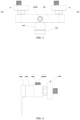
- 1-faucet body 101-water inlet port, 102-water outlet port, 103-first stepped surface, 104-convex rib, 2-water inlet assembly, 3-piston, 301-communication hole, 302-second stepped surface, 303-protruding portion, 4-elastic member, 5-housing, 501-housing cover, 502-bottom plate, 503-first screw, 6-handle, 7-semicircular decorative cover, 8-valve core gland, 9-valve core, 10-first sealing member, 11-second sealing member, 12-second screw, 13-connecting joint, 14-third sealing member, 15-water level joint, 16-gasket, 17-hexagonal nut, 18-curved foot decorative cover, and 19-curved foot.
- an embodiment of the present application provides a faucet including a faucet body 1 and a water inlet assembly 2.
- the faucet body 1 has a water inlet port 101.
- the faucet further includes a freezing crack prevention assembly.
- the freezing crack prevention assembly includes a piston 3 and an elastic member 4.
- the piston 3 is connected between the water inlet port 101 and the water inlet assembly 2.
- the piston 3 is provided with a communication hole 301 for communicating the water inlet assembly 2 with the water inlet port 101.
- Two ends of the elastic member 4 abut against the water inlet assembly 2 and the piston 3, respectively, to enable the piston 3 to move relative to the faucet body 1 and the water inlet assembly 2.
- the piston 3 is connected between the faucet body 1 and the water inlet assembly 2, and the piston 3 is provided with a communication hole 301 to communicate the water inlet assembly 2 with the water inlet port 101 of the faucet body 1, so that water inlet of the faucet is not affected.
- the two ends of the elastic member 4 abut against the water inlet assembly 2 and the piston 3, respectively.
- the elastic member 4 is deformable so that the piston 3 can move to change a volume of an inner cavity of the faucet body 1.
- the faucet is in a normal use state.
- water inside the faucet turns into ice, and the volume is 1.1 times the previous volume.
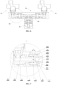
- FIGS. 8 and 9 when water in the inner cavity of the faucet body 1 turns into ice so that the volume thereof is expanded significantly, a force pushing the piston 3 is greater than an elastic force applied to the piston 3 by the elastic member 4, so that the piston 3 moves towards a side where the water inlet assembly 2 is located, expanding the volume of the inner cavity of the faucet body 1 and compressing the elastic member 4, thus achieving the purposes of protecting the faucet body 1 and preventing the faucet body 1 from freezing crack and burst.
- the purpose of preventing the faucet from freezing crack is achieved by providing a freezing crack prevention assembly in the faucet body 1 to expand the volume of the inner cavity of the faucet body 1 to supplement the volume expansion caused by water turning into ice.
- the freezing crack prevention assembly is an automatic adjusting assembly, which does not require a manual operation, and does not have any external auxiliary parts, and therefore is convenient to use.
- the realization of the freezing crack prevention function only requires adding a piston 3 and an elastic member 4 in the faucet, which is simple in structure and low in cost.
- one end of the piston 3 is sleeved outside the water inlet assembly 2, and the other end extends into the water inlet port 101.
- a first sealing member 10 is provided between the piston 3 and the water inlet port 101, and a second sealing member 11 is provided between the piston 3 and the water inlet assembly 2.
- the first sealing member 10 is sleeved at and mounted to one end of the piston 3, and the one end of the piston 3 and the first sealing member 10 extend into the water inlet port 101 of the faucet body 1, realizing the sealing connection between the faucet body 1 and the piston 3.
- the second sealing member 11 is sleeved at and mounted to one end of the water inlet assembly 2, and the one end of the water inlet assembly 2 and the second sealing member 11 extend into the communication hole 301 of the piston 3, realizing the sealing connection between the water inlet assembly 2 and the piston 3.
- the first sealing member 10 may include one or more (two or more) O-rings
- the second sealing member 11 may include one or more (e.g., two) O-rings.
- a through-flow cross-sectional area S2 of a portion of the water inlet port 101 sleeved outside the piston 3 is larger than a through-flow cross-sectional area S 1 of a portion of the communication hole 301 sleeved outside the water inlet assembly 2.
- the piston 3 moves towards the water inlet assembly 2 by a distance L, making the increased inner cavity volume (S2 ⁇ L-S1 ⁇ L) of the faucet greater than 10% of the inner cavity volume of the faucet body 1, so as to adapt to the 1.1 times change in volume when water in the faucet body 1 turns into ice.
- the water inlet port 101 is a first stepped hole which has a first stepped surface 103, and the piston 3 is configured to be able to abut against the first stepped surface 103 under the action of the elastic member 4 for positional restriction.
- the through-flow cross-sectional area of one end of the communication hole 301 close to the first stepped surface 103 is smaller than the through-flow cross-sectional area of a hole on the first stepped surface 103.
- the through-flow cross-sectional area of one end of the communication hole 301 close to the first stepped surface 103 is smaller than the through-flow cross-sectional area of a hole on the first stepped surface 103, so that an inner side of the end surface of one end of the piston 3 extending into the water inlet port 101 forms a protruding portion 303 protruding from the hole on the first stepped surface 103.
- the piston 3 can be pushed towards the side where the water inlet assembly 2 is located by pushing the protruding portion 303 of the piston 3.
- the end surface of one end of the piston 3 extending into the water inlet port 101 may not completely fit with the first stepped surface 103.
- the piston 3 can be pushed by pushing the end surface of one end of the piston 3 extending into the water inlet port 101.
- the first stepped surface 103 is provided with a convex rib 104, and the piston 3 is configured to be able to abut against the convex rib 104 under the action of the elastic member 4.
- the convex rib 104 may be an annular convex rib.
- the piston 3 in the normal use state, the piston 3 abuts against the convex rib 104 on the first stepped surface 103 under the action of the elastic member 4, so that there is a water storage gap between the end surface of the piston 3 extending into the water inlet port 101 and the first stepped surface 103.
- the piston 3 can be pushed towards the side where the water inlet assembly 2 is located by pushing the end surface of the piston 3 extending into the water inlet port 101.
- the end surface of one end of the piston 3 extending into the water inlet port 101 is provided with a convex rib, and the piston 3 is configured such that the convex rib can abut against the first stepped surface 103 under the action of the elastic member 4.
- the communication hole 301 is a second stepped hole.
- the through-flow cross-sectional area of one end of the second stepped hole close to the water inlet assembly 2 is larger than the through-flow cross-sectional area of one end of the second stepped hole close to the water inlet port 101.
- the second stepped hole has a second stepped surface 302, and the piston 3 is configured to be able to abut against the water inlet assembly 2 through the second stepped surface 302 for positional restriction.
- the communication hole 301 in the piston 3 is a stepped hole.
- the piston 3 can move towards the side where the water inlet assembly 2 is disposed.
- the second stepped surface 302 of the piston 3 abuts against the end surface of one end of the water inlet assembly 2 extending into the communication hole 301, the piston 3 is restricted from moving continuously, thus limiting the position of the piston 3.
- a displacement stroke of the piston 3 is limited by the cooperation between the end surface of the piston 3 and the first stepped surface 103 of the water inlet port 101, and the cooperation between the end surface of the water inlet assembly 2 and the second stepped surface 302 of the communication hole 301.
- the faucet body 1 has two water inlet ports 101, namely a cold water inlet port and a hot water inlet port.
- Freezing crack prevention assemblies are provided between the hot water inlet port of the faucet body 1 and the hot water inlet assembly and between the cold water inlet port of the faucet body 1 and the cold water inlet assembly, respectively.
- the piston 3 of each freezing crack prevention assembly moves by a distance L, making the increased inner cavity volume 2 ⁇ (S2 ⁇ L-S1 ⁇ L) of the faucet greater than 10% of the inner cavity volume of the faucet body 1, so as to adapt to the 1.1 times change in volume when water in the faucet body 1 turns into ice. It should be understood that the moving distances of the pistons 3 of the two freezing crack prevention assemblies may not be equal.
- the faucet further includes a housing 5.
- the faucet body 1 is fixed in the housing 5, and one end of the water inlet assembly 2 extends into the housing 5 and is fixedly connected with the housing 5.
- the water inlet assembly 2 and the faucet body 1 are both fixed to the housing 5, so that the housing 5 bears the installation and stress of all parts in the faucet.
- the housing 5 bears the main installation locking force, so that the strength is guaranteed.
- the faucet body 1 only plays the role of sealing and water passing. Modularization of the faucet is realized, and different appearance shapes can be achieved by replacing different housings 5, thus achieving high practicability.
- the faucet further includes a handle 6 and a valve core 9.
- the handle 6 is connected with the valve core 9 and can drive the valve core 9 to move.
- the valve core 9 is connected with the faucet body 1, and a water passage in the valve core 9 communicates with the water inlet port 101 and the water outlet port 102 on the faucet body 1, so as to realize the opening and closing of the faucet and the adjustment of the temperature of the outlet water by the handle 6 driving the valve core 9 to move.
- the valve core 9 may be fixedly installed in the housing 5 through a valve core gland 8, and a semicircular decorative cover 7 is provided between the valve core 9 and the handle 6.
- the housing 5 includes a housing cover 501 and a bottom plate 502, and the housing cover 501 and the bottom plate 502 are fixed by a first screw 503.
- the faucet body 1 is fixed in the housing cover 501 by a second screw 12.
- the water inlet assembly 2 includes a connecting joint 13, a third sealing member 14, a water level joint 15, a gasket 16, a hexagonal nut 17, a curved foot decorative cover 18 and a curved foot 19.
- One end of the connecting joint 13 extends into the communication hole 301 of the piston 3.
- the second sealing member 11 is provided between the connecting joint 13 and the piston 3.
- the elastic member 4 (a spring) is sleeved outside the connecting joint 13, and the two ends of the elastic member 4 abut against the connecting joint 13 and the piston 3, respectively.
- One end of the water level joint 15 extends into the connecting joint 13.
- the third sealing member 14 is provided between the water level joint 15 and the connecting joint 13.
- the water level joint 15 is threadedly connected with the housing cover 501 of the housing 5.
- the other end of the water level joint 15 is fixed to the curved foot 19 by the hexagonal nut 17, and the gasket 16 is provided between the water level joint 15 and the curved foot 19.
- the curved foot decorative cover 18 is fixed to the curved foot 19.
- the connecting joint 13, the water level joint 15 and the curved foot 19 are each provided with a water passing cavity, and the water passing cavities of the connecting joint 13, the water level joint 15 and the curved foot 19 are sequentially communicated to form a water inlet passage of the water inlet assembly 2.
- the faucet body 1 can be made of plastic.
- the housing 5 can be made of metal.
- the housing 5 is made of zinc alloy.
- the metal housing 5 has high structural strength, so that the strength is guaranteed when the metal housing 5 bears the installation and stress of all parts of the faucet, and different appearance shapes can be achieved by replacing different metal housings 5.
- the piston 3 can be made of plastic.
- the elastic member 4 includes a spring.
- freezing crack prevention is achieved by expanding the volume of the inner cavity of the faucet body to supplement the expanded volume due to water turning into ice, rather than by leaving no water in the faucet (or draining off water).
- the freezing crack prevention assembly is an automatic device, which does not need any manual operation and is convenient to use.
- the freezing crack prevention assembly is provided in the faucet, and only includes a piston and an elastic member. Since the freezing crack prevention assembly includes few parts, the installation thereof is convenient and the cost is low.
Landscapes
- Health & Medical Sciences (AREA)
- Life Sciences & Earth Sciences (AREA)
- Engineering & Computer Science (AREA)
- Hydrology & Water Resources (AREA)
- Public Health (AREA)
- Water Supply & Treatment (AREA)
- Domestic Plumbing Installations (AREA)
- Lift Valve (AREA)
Applications Claiming Priority (1)
| Application Number | Priority Date | Filing Date | Title |
|---|---|---|---|
| CN202021891804.2U CN213871288U (zh) | 2020-09-02 | 2020-09-02 | 龙头 |
Publications (1)
| Publication Number | Publication Date |
|---|---|
| EP3964652A1 true EP3964652A1 (de) | 2022-03-09 |
Family
ID=73043165
Family Applications (1)
| Application Number | Title | Priority Date | Filing Date |
|---|---|---|---|
| EP20205157.9A Withdrawn EP3964652A1 (de) | 2020-09-02 | 2020-11-02 | Armatur |
Country Status (2)
| Country | Link |
|---|---|
| EP (1) | EP3964652A1 (de) |
| CN (1) | CN213871288U (de) |
Cited By (1)
| Publication number | Priority date | Publication date | Assignee | Title |
|---|---|---|---|---|
| CN114811145A (zh) * | 2022-04-27 | 2022-07-29 | 宁波方太厨具有限公司 | 防冻裂阀体及包含其的燃气热水器 |
Citations (3)
| Publication number | Priority date | Publication date | Assignee | Title |
|---|---|---|---|---|
| JPH05263985A (ja) * | 1992-03-17 | 1993-10-12 | Tube Forming:Kk | 水撃防止装置 |
| JPH0581597U (ja) * | 1992-04-08 | 1993-11-05 | エヌテーシー工業株式会社 | ウオーターハンマー防止装置 |
| EP1002984A2 (de) * | 1998-11-21 | 2000-05-24 | Frey, Conrad | Druckschlag- und Geräuschdämpfer für Wasserleitung und -armaturen |
-
2020
- 2020-09-02 CN CN202021891804.2U patent/CN213871288U/zh active Active
- 2020-11-02 EP EP20205157.9A patent/EP3964652A1/de not_active Withdrawn
Patent Citations (3)
| Publication number | Priority date | Publication date | Assignee | Title |
|---|---|---|---|---|
| JPH05263985A (ja) * | 1992-03-17 | 1993-10-12 | Tube Forming:Kk | 水撃防止装置 |
| JPH0581597U (ja) * | 1992-04-08 | 1993-11-05 | エヌテーシー工業株式会社 | ウオーターハンマー防止装置 |
| EP1002984A2 (de) * | 1998-11-21 | 2000-05-24 | Frey, Conrad | Druckschlag- und Geräuschdämpfer für Wasserleitung und -armaturen |
Cited By (3)
| Publication number | Priority date | Publication date | Assignee | Title |
|---|---|---|---|---|
| CN114811145A (zh) * | 2022-04-27 | 2022-07-29 | 宁波方太厨具有限公司 | 防冻裂阀体及包含其的燃气热水器 |
| CN114811145B (zh) * | 2022-04-27 | 2023-03-10 | 宁波方太厨具有限公司 | 防冻裂阀体及包含其的燃气热水器 |
| CN116025756A (zh) * | 2022-04-27 | 2023-04-28 | 宁波方太厨具有限公司 | 防冻裂阀体及包含其的燃气热水器 |
Also Published As
| Publication number | Publication date |
|---|---|
| CN213871288U (zh) | 2021-08-03 |
Similar Documents
| Publication | Publication Date | Title |
|---|---|---|
| CN100387882C (zh) | 开闭阀装置和冷热水混合水龙头 | |
| TW200641281A (en) | Valve assembly having rigid seating surfaces | |
| EP3964652A1 (de) | Armatur | |
| EP1479836A2 (de) | Unsichtbare Befestigung eines Wasserventilkörpers und Bedienungsanordnung | |
| EP3845993B1 (de) | Druckreduzierventil und ausziehbarer wasserhahn | |
| WO2000018382A3 (de) | Hydraulisches wegeventil | |
| CN216344067U (zh) | 一种用于防冻裂的龙头组件和龙头 | |
| CA2434609A1 (en) | Flush valve diaphragm orifice insert and rib design | |
| CN206693347U (zh) | 一种具有自洁功能的冲洗马桶盖 | |
| CN220910718U (zh) | 一种防冻裂装置及出水装置 | |
| CN107035876B (zh) | 一种低水损减压型倒流防止器 | |
| US20030122097A1 (en) | Flush-mount retrofit fluid control switch | |
| CN214889097U (zh) | 一种止水止回阀 | |
| CN217653283U (zh) | 一种防冻淋浴装置 | |
| CN218913829U (zh) | 一种防冻龙头阀芯、出水装置 | |
| US11846955B2 (en) | Cold water discharge structure | |
| CN212839712U (zh) | 一种电磁阀 | |
| CN216130252U (zh) | 一种防冻裂龙头 | |
| CN214466389U (zh) | 一种防冻角度减压阀 | |
| CN219176952U (zh) | 冲洗阀 | |
| CN221221609U (zh) | 一种暗装式冲洗阀 | |
| CN215981012U (zh) | 一种高脚限流阀组件 | |
| CN217784284U (zh) | 一种自动切换出水装置 | |
| CN221824543U (zh) | 一种具有防冻裂功能的卫浴出水阀 | |
| CN216279641U (zh) | 一种洒水车用气动阀门 |
Legal Events
| Date | Code | Title | Description |
|---|---|---|---|
| PUAI | Public reference made under article 153(3) epc to a published international application that has entered the european phase |
Free format text: ORIGINAL CODE: 0009012 |
|
| STAA | Information on the status of an ep patent application or granted ep patent |
Free format text: STATUS: REQUEST FOR EXAMINATION WAS MADE |
|
| 17P | Request for examination filed |
Effective date: 20201102 |
|
| AK | Designated contracting states |
Kind code of ref document: A1 Designated state(s): AL AT BE BG CH CY CZ DE DK EE ES FI FR GB GR HR HU IE IS IT LI LT LU LV MC MK MT NL NO PL PT RO RS SE SI SK SM TR |
|
| STAA | Information on the status of an ep patent application or granted ep patent |
Free format text: STATUS: EXAMINATION IS IN PROGRESS |
|
| 17Q | First examination report despatched |
Effective date: 20230220 |
|
| STAA | Information on the status of an ep patent application or granted ep patent |
Free format text: STATUS: THE APPLICATION HAS BEEN WITHDRAWN |
|
| 18W | Application withdrawn |
Effective date: 20230620 |