EP3964800B1 - Détection de position triaxiale pour systèmes de caméra utilisant des capteurs à effet hall - Google Patents
Détection de position triaxiale pour systèmes de caméra utilisant des capteurs à effet hall Download PDFInfo
- Publication number
- EP3964800B1 EP3964800B1 EP20194083.0A EP20194083A EP3964800B1 EP 3964800 B1 EP3964800 B1 EP 3964800B1 EP 20194083 A EP20194083 A EP 20194083A EP 3964800 B1 EP3964800 B1 EP 3964800B1
- Authority
- EP
- European Patent Office
- Prior art keywords
- magnet
- hall sensor
- hall
- sensors
- sensor
- Prior art date
- Legal status (The legal status is an assumption and is not a legal conclusion. Google has not performed a legal analysis and makes no representation as to the accuracy of the status listed.)
- Active
Links
Images




Classifications
-
- H—ELECTRICITY
- H04—ELECTRIC COMMUNICATION TECHNIQUE
- H04N—PICTORIAL COMMUNICATION, e.g. TELEVISION
- H04N17/00—Diagnosis, testing or measuring for television systems or their details
- H04N17/002—Diagnosis, testing or measuring for television systems or their details for television cameras
-
- G—PHYSICS
- G01—MEASURING; TESTING
- G01D—MEASURING NOT SPECIALLY ADAPTED FOR A SPECIFIC VARIABLE; ARRANGEMENTS FOR MEASURING TWO OR MORE VARIABLES NOT COVERED IN A SINGLE OTHER SUBCLASS; TARIFF METERING APPARATUS; MEASURING OR TESTING NOT OTHERWISE PROVIDED FOR
- G01D5/00—Mechanical means for transferring the output of a sensing member; Means for converting the output of a sensing member to another variable where the form or nature of the sensing member does not constrain the means for converting; Transducers not specially adapted for a specific variable
- G01D5/12—Mechanical means for transferring the output of a sensing member; Means for converting the output of a sensing member to another variable where the form or nature of the sensing member does not constrain the means for converting; Transducers not specially adapted for a specific variable using electric or magnetic means
- G01D5/14—Mechanical means for transferring the output of a sensing member; Means for converting the output of a sensing member to another variable where the form or nature of the sensing member does not constrain the means for converting; Transducers not specially adapted for a specific variable using electric or magnetic means influencing the magnitude of a current or voltage
- G01D5/142—Mechanical means for transferring the output of a sensing member; Means for converting the output of a sensing member to another variable where the form or nature of the sensing member does not constrain the means for converting; Transducers not specially adapted for a specific variable using electric or magnetic means influencing the magnitude of a current or voltage using Hall-effect devices
- G01D5/145—Mechanical means for transferring the output of a sensing member; Means for converting the output of a sensing member to another variable where the form or nature of the sensing member does not constrain the means for converting; Transducers not specially adapted for a specific variable using electric or magnetic means influencing the magnitude of a current or voltage using Hall-effect devices influenced by the relative movement between the Hall device and magnetic fields
-
- G—PHYSICS
- G02—OPTICS
- G02B—OPTICAL ELEMENTS, SYSTEMS OR APPARATUS
- G02B27/00—Optical systems or apparatus not provided for by any of the groups G02B1/00 - G02B26/00, G02B30/00
- G02B27/64—Imaging systems using optical elements for stabilisation of the lateral and angular position of the image
- G02B27/646—Imaging systems using optical elements for stabilisation of the lateral and angular position of the image compensating for small deviations, e.g. due to vibration or shake
-
- G—PHYSICS
- G02—OPTICS
- G02B—OPTICAL ELEMENTS, SYSTEMS OR APPARATUS
- G02B7/00—Mountings, adjusting means, or light-tight connections, for optical elements
- G02B7/02—Mountings, adjusting means, or light-tight connections, for optical elements for lenses
Definitions
- the present invention relates to a Hall sensor IC for a camera system configured to determine a triaxial position of a lens module using Hall sensors, to a camera system comprising the Hall sensor IC, and to a method for determining a triaxial position of a lens module using the Hall sensor IC.
- Smartphones have become an indispensable part of life in nowadays' society. In the past years they have evolved to an extent in which they have become powerful devices with which we can perform almost any task. Smartphones have allowed to merge into one single device the functions which in the past were performed by different devices.
- a central feature of a smartphone nowadays is the camera. Smartphone cameras are becoming more and more compact while quality and resolution are improved throughout the recent generations. Also compact camera devices are evolving and their quality and resolution has been improving while their size has been reduced.
- AutoFocus (AF) is a must-have feature of most smartphone cameras
- OIS Optical Image Stabilization
- the lens barrel needs to translate in the optical axis (Z-axis), while for OIS, it jiggles in X and Y directions which are in the plane perpendicular to the optical axis. Movement in all dimensions should be with an accuracy of micrometers.
- the triaxial (X-Y-Z) movements are driven by three separate motors.
- Some popular motor technologies used for AF and OIS are Voice Coil Motor (VCM) or Shape Memory Alloy (SMA).
- VCM Voice Coil Motor
- SMA Shape Memory Alloy
- the position of the lens in one direction can be accurately measured by Hall sensors to feedback to the control loop of the camera system.
- Hall sensors consist of a magnet, usually mounted on the moving part (the lens barrel), and an Integrated Circuit (IC) containing a Hall sensor mounted on the fixed part (e.g. the module base or housing).
- IC Integrated Circuit
- control loop uses image contrast as an indication of sharpness and an algorithm tries to scan the focal length until the sharpness is maximized. This method of AF does not require additional components in the camera system, but it is generally slow.
- More modern or higher-priced designs include position sensors (Hall sensors) to assist the control loop of the camera system.
- Hall sensors position sensors
- the OIS is controlled by a feed forward mechanism, which may lead to some reduction in stabilization quality.
- US 2015/0015729 A1 discloses a position detection apparatus that includes an AF mechanism (an AF position sensor) and an OIS mechanism (an OIS position sensor) by using a closed loop control, in which a magnet is commonly used as an autofocus magnet and an optical image stabilization magnet to achieve downsizing.
- the position detection apparatus includes the autofocus mechanism that moves a lens along an optical axis (Z axis) of the lens, and the optical image stabilization mechanism that moves the lens in an in-plane direction orthogonal to the optical axis.
- a permanent magnet is secured to the lens, and moves according to the movement of the lens. The amount of movement thereof is detected by position sensors.
- FIG.1 An example of a state-of-the-art camera system of a smartphone is shown in Fig.1 , where the Hall sensor is used for linear position sensing in the Z-direction for AF operation.
- the lens barrel is hung on a system of springs and two stages of AF (moving in Z direction) and OIS (moving in X-Y directions).
- the springs, AF and OIS motors are not shown in Fig. 1 .
- the Hall sensor may be integrated in the lens driver IC or any IC 16 inside the camera module.
- the lens driver IC is mounted vertically (as viewed in the perspective of Fig.
- the magnetization of the magnet is in the Z-direction. It produces an (almost) linearly changing magnetic field around the location of the Hall sensor.
- the vertical magnetic field (Bx) on the Hall sensor changes linearly, which is used to calculate the lens position.
- X and Y position sensors can additionally be placed at different locations to assist the OIS operation.
- the design of separated Hall sensor chips makes the module highly complex and costly.
- the invention provides Hall sensor integrated circuit, IC, for a camera system, the Hall sensor IC comprising at least three Hall sensors spaced apart from each other in a non-aligned configuration, and configured to measure a magnetic field generated based on a position of one magnet arranged in the camera system.
- the invention provides a Hall sensor IC comprising at least three Hall sensors which can measure the magnetic field caused by one single magnet.
- the Hall sensor IC is a single die, a (small) block of semiconductor material on which a certain functional circuit is manufactured. A die is thus a block of semiconductor material containing one copy of the functional circuit. An IC or die can also be referred to as a chip.
- the Hall sensors used in the art usually reside in separate ICs, and one Hall sensor is used in combination with one magnet to detect position in one direction. If the position in an additional direction is to be determined, a separated magnet and Hall sensor (in a separated IC) are placed at a different location. The presence of these additional components requires additional space.
- the position of the magnet in three dimensions can be determined.
- a non-aligned configuration that is, a non-straight-line configuration or a configuration in which the at least three Hall sensors do not form a straight line.
- the Hall sensor IC comprises a control unit configured to determine a three dimensional, 3D, position of the magnet based on a combination of the magnetic fields measured by the at least three Hall sensors.
- the at least three Hall sensors are each arranged within the Hall sensor IC forming a geometrical configuration with respect to each other with central symmetry or axial symmetry. According to embodiments, the at least three Hall sensors are equally spaced from each other. The specific distribution of the Hall sensors being equally spaced apart can provide more accurate measurements, because it allows to achieve a maximum distance between all the Hall sensors.
- the Hall sensor IC further comprises a memory configured to store information required to obtain the three dimensional position of the magnet based on the combination of the magnetic fields measured by the at least three Hall sensors.
- each of the at least three Hall sensors is configured to be individually enabled and disabled. This allows the Hall sensor IC to be adapted to different system requirements, and improves its versatility and compatibility.
- the Hall sensor IC comprises three Hall sensors arranged within the Hall sensor IC forming a circular configuration or triangular configuration.
- the Hall sensor IC comprises four Hall sensors arranged within the Hall sensor IC forming a circular configuration or squared configuration. This redundancy of having (at least one) additional Hall sensor allows to improve accuracy of the measurements and thus robustness of the system.
- the four Hall sensors are arranged in a circular configuration, the four Hall sensors can be arranged on the circumference of a circle. In some embodiments, the four Hall sensors are symmetrical around the center of the circle.
- the four hall sensors can be arranged in any quadrilateral configuration, for example, in a parallelogram configuration, in a trapezoidal configuration or in a squared configuration.
- the Hall sensor IC is configured to be integrated in another IC comprised in the camera system, the another IC being one of a list comprising but not limited to: a lens driver, a motor controller, an image sensor, an image sensor controller, an image processor, or any other IC present in the camera system.
- the invention provides a camera system comprising: a housing; a lens module arranged inside the housing; a Hall sensor IC as described in the previous paragraphs arranged inside the housing; and a magnet arranged inside the housing and facing the Hall sensor IC, wherein one of the Hall sensor IC and the magnet is arranged on a first inner side of the housing and the other one of the Hall sensor IC and the magnet is arranged on a first side of the lens module facing the first inner side of the housing.
- the Hall sensor IC is arranged on the first inner side of the housing, and the magnet is mounted on the first side of the lens module.
- the invention advantageously provides a camera system (camera module) design with a reduced size and complexity which allows for accurate three dimensional lens position determination. This is because, contrary to what is known in the art, the present invention requires only one magnet and one Hall sensor IC comprising at least three Hall sensors which measure a magnetic field generated based on the only one magnet, and this configuration allows to determine a position of the lens module in three directions X, Y and Z.
- the first inner side of the housing corresponds to a side perpendicular to the optical axis of the camera system and opposite to a side with an opening in the housing through which the lens module moves.
- the Hall sensor IC may thus be placed at the base of the camera system, and the magnet may be thus placed on the edge of the lens module closest to the base of the camera system.
- the first inner side of the housing corresponds to a side parallel to the optical axis of the camera system and adjacent to a side with an opening in the housing through which the lens module moves.
- the Hall sensor IC may thus be on a side wall of the camera system, and the magnet is thus placed on the edge of the lens module closest to that side wall of the camera system.
- a distance between an edge of the magnet closest to the Hall sensor IC and the Hall sensor IC is not greater than 2 millimetres (mm), more preferably not greater than 1 mm, and more preferably not greater than 0.5 mm.
- the at least three Hall sensors of the Hall sensor IC are all Hall sensors with horizontal Hall plates and the magnet is magnetized in a direction perpendicular to a plane of the Hall sensor IC.
- an orientation of the magnet and an orientation of the at least three Hall sensors of the Hall sensor IC are such that a gradient of a magnetic field component measured by the at least three Hall sensors is maximized and/or a linearity of the magnetic field component measured by the at least three Hall sensors is maximized.
- the invention provides a method for determining a position of a lens module arranged inside a camera system, comprising: measuring, by each of the at least three Hall sensors of the Hall sensor IC as described in the previous paragraphs, a magnetic field generated based on a position of the magnet arranged inside the camera system, and combining the magnetic field measured by each of the at least three Hall sensors to determine a three dimensional, 3D, position of the magnet, wherein one of the Hall sensor IC and the magnet is arranged on a first inner side of a housing of the camera system, and the other one of the Hall sensor IC and the magnet is arranged on a first side of the lens module facing the first inner side of the housing.
- the method comprises comparing the combined measured magnetic field with predefined information stored in a look-up table.
- the method comprises using predefined information stored in the form of at least one parametric function for transforming the magnetic fields measured by the at least three Hall sensors into the 3D position of the magnet.
- the three dimensional position of the source can be determined.
- the possible magnetic fields measured by the Hall sensors can be characterized for the different positions of the magnet in the directions X, Y and Z.
- One approach is to store in the memory of the Hall sensor IC or of another IC in communication with the Hall sensor IC a look-up table in which the values of the magnetic fields measured by the Hall sensors can be linked to the three dimensional (triaxial) position of the magnet.
- Another approach is to store the information in the form of parametric functions which have been previously determined by characterizing the magnetic field measurements for different positions. It should be evident that other approaches are available and known for the person skilled in the art.
- Fig. 2 schematically shows a design of a camera system according to embodiments of the present invention.
- a camera system that features both AF and OIS, with 3D lens position sensing using one single magnet and one single Hall sensor IC containing a plurality of integrated Hall sensors. In this way, the system is less complex, low cost and compact while precise lens position control can still be maintained.
- a configuration of a camera system 10 comprising a housing 12, an image sensor 13, a lens module or lens barrel 14, a Hall sensor IC 16 and a single magnet 18.
- a lens position in all X, Y, and Z axes (the X and Z axes are depicted in the figure, and the Y axis extends in the direction perpendicular to the X and the Z axes) can be determined.
- the Hall sensor IC 16 may be mounted on a first inner side of the housing, such as on the bottom plate of the camera system, e.g., a base of the camera system, e.g., a side perpendicular to the optical axis of the camera system and opposite to a side of the housing with an opening through which the lens barrel moves.
- the Hall sensor IC may however also be mounted on a side wall of the camera system, a side parallel to the optical axis, or in any other suitable position, provided that the magnet is in the vicinity or close proximity of the Hall sensor IC, and that the Hall sensor IC and the magnet have appropriate relative orientations.
- the Hall sensor IC may be mounted on a Printed Circuit Board (PCB) arranged on the bottom of the camera system.
- the Hall sensor IC may be integrated into another IC comprised in the camera system, a larger IC, such as a lens driver IC, a memory, a motor driver, a digital signal processor (DSP), a digital block for sensing and control algorithms, an image sensor 13, an image sensor controller, an image processor, or other ICs present in the camera system.
- the magnet 18 may be mounted at the edge of the lens module 14 closest to the Hall sensor IC, such as the lowest edge of the lens module.
- the magnet 18 should be placed on one wall of the lens module 14 facing the inner wall of the housing where the Hall sensor IC is placed. It should be noted that also the magnet 18 can be placed on one inner wall of the housing 12, and in such case the Hall sensor IC 16 should be placed on one wall of the lens module 14 facing the one wall where the magnet is located.
- the magnetization of the magnet 18 shown in Fig. 2 is in the Z direction and the Hall sensor IC 16 is located along the X-Y plane and comprises Hall sensor with horizontal Hall plates. This is however not limiting, and the magnetization of the magnet could be in a different direction. However, the orientation of the magnetization direction is important to design the operation principle of the Hall sensors 17. It should be chosen such that when the lens module (where the magnet or the Hall sensor IC is located) moves, a changing magnetic field in the sensitive direction of the Hall sensors is present and sizeable. In some cases, such as for simple implementations where only the position in one direction needs to be determined, and therefore the strength of the signal is enough to determine the position, the field gradient is preferably linear, because it is simple.
- the Z component of the magnetic field on the Hall sensor IC plane shows a nonlinear curve (this can be seen in Fig. 9 ); i.e. the magnetic field gradient changes with the distance, and more specifically becomes larger when the lens module 14 gets closer to the Hall sensor IC.
- the position of the Hall sensors may be chosen so that they are placed at the X and Y positions that are located in the slope of the curve, such as a sufficiently large magnetic field and sufficiently large gradient of the magnetic field is provided.
- the orientation of the magnet with respect to the Hall sensors of the Hall sensor IC should be chosen such that sensor signals are maximized and the solution of the calculation results in an accurate position in all dimensions X, Y and Z.
- the orientations of the first embodiment - the at least three Hall sensors being Hall sensors with horizontal Hall plates and the magnet being magnetized in a direction perpendicular to a plane of the Hall sensor IC - is such that the gradient of a magnetic field component measured by the at least three Hall sensors is maximized in all X, Y and Z directions.
- the result of positioning may be good for Z and Y directions, but less accurate for X direction, because the magnetic field extends substantially along the X axis.
- the magnet 18 has a cylindrical shape, where the rotational axis is in the direction of the magnetization of the magnet (in this case the Z direction).
- the magnet may have other shapes such as a cuboid.
- the distance between the lower edge of the magnet and the Hall sensor IC plane (where active silicone devices locate) may not be greater than 2millimetre (mm), or more preferably, not greater than 1 mm, or even more preferably, not greater than 0.5mm. The shorter the distance, the more accurate will be the measurements, because the stronger will be the detected magnetic field and the greater the field gradient. The maximum distance may be determined by the sensitivity of the Hall sensors.
- the magnet 18 creates a magnetic field on the Hall sensor IC plane.
- the Hall sensor IC comprises Hall sensors with horizontal Hall plates, and therefore the perpendicular component of the magnetic field, Bz, is in the sensitive direction of the Hall sensors. It should however be evident for the skilled person that if Hall sensors with vertical Hall plates are used, a different component of the magnetic field would be of interest.
- a Hall sensor comprises Hall plates. The Hall plates are based on the Hall effect, which consists of the generation of a voltage difference (the Hall voltage) across an electrical conductor, as a result of deflection of electronic charges within the conductor when a magnetic field is applied perpendicular to the current. The most popular Hall sensors are based on horizontal Hall plates.
- Hall sensors In these horizontal Hall plates, the current flows in the in-plane direction and they are sensitive to a component of the magnetic field perpendicular to the silicon plane in which the Hall sensor is placed.
- Another type of Hall sensors are based on vertical Hall plates. In these vertical Hall plates, current flows essentially in the direction perpendicular to the silicon plate, and they are sensitive to the in-plane components of magnetic field.
- Each Hall sensor usually consists of four or more Hall plates oriented at different directions for the so-called "current spinning technique".
- the direction of the current is alternately rotated by switching terminals of the Hall plates to cancel out offset voltage, planar Hall effect, stress effect, and to reduce 1/f noise.
- the Hall sensor IC 16 is constituted in a single silicon die or in an overmold packaged IC or chip. According to embodiments of the present invention, the Hall sensor IC 16 comprises at least three Hall sensors 17 configured to measure a magnetic field generated based on a position of the magnet 18.
- the Hall sensor IC may also comprise a control unit configured to determine a three dimensional position of the lens module (or lens, or lens barrel) based on a combination of the magnetic field values measured by the at least three Hall sensors. In some embodiments the control unit may however not be part of the Hall sensor IC but interact with the Hall sensor IC to control it.
- One single silicon die comprises at least three Hall sensors. Each of these Hall sensors is configured to measure a component of the magnetic field, and with the measured magnetic field of the at least three Hall sensors, the three dimensional position of the lens module can be determined.
- Each of the Hall sensors 17 is placed at a different location within the Hall sensor IC 16 and they should not lie on a same straight line, as in such case a 3D determination of the position would not be possible.
- Each Hall sensor obtains a measurement of the magnetic field (more specifically of the component of the magnetic field to which the Hall sensor is sensitive). This magnetic field will vary depending on the relative position of the magnet 18 with respect to the Hall sensor IC, and since either the magnet 18 or the Hall sensor IC 16 is mounted on the lens module, by measuring the different magnetic fields, different positions of the lens module can be determined.
- Hall sensors are used to determine the position of the magnet (and therefore the lens) in one single direction, because one Hall sensor IC in the art includes only one Hall sensor.
- the distribution of the at least three Hall sensors can be understood as at least three points which are spaced apart from each other (and thus forming a plane instead of a straight line).
- the at least three Hall sensors form a geometrical configuration with a central symmetry (such as a circle) or axial symmetry (such as a triangle, rectangle, pentagon, hexagon, or the like).
- Fig. 3 depicts a schematic configuration of a Hall sensor IC for a camera system according to the first embodiment of the present invention.
- the Hall sensor IC 16 comprises three Hall sensors (17-1, 17-2, 17-3) spaced apart from each other, and not forming any specific symmetric geometrical configuration.
- Fig. 4 depicts another schematic configuration of a Hall sensor IC for a camera system according to the first embodiment of the present invention.
- the Hall sensor IC 16 comprises three Hall sensors (17-1, 17-2, 17-3), in this configuration equally spaced apart from each other, and forming a circular configuration, or a triangular configuration.
- the Hall sensors should be placed in the Hall sensor IC as far apart from each other as possible to improve accuracy, but within an area having a sufficiently large absolute value of the magnetic field, and having a sufficiently large magnetic field gradient.
- a suitable way to achieve a maximum separation among all Hall sensors is to have them equally apart from each other.
- Fig. 5 depicts another schematic configuration of a Hall sensor IC for a camera system according to the first embodiment of the present invention.
- the Hall sensor IC 16 comprises four Hall sensors (17-1, 17-2, 17-3, 17-4), in this configuration equally spaced apart from each other, and forming a circular configuration, or a square configuration.
- three Hall sensors 17 measuring the magnetic field based on one magnet suffice to determine the position of the magnet 18 (and thus the lens module 14)
- the more Hall sensors are used, the more redundant information is generated which can in turn be used to improve the accuracy of the position determination.
- the more Hall sensors used the more space is required, and the more operations need to be performed, resulting in a less compact and more complex system. A trade-off should therefore be achieved.
- the center of the geometrical configuration formed by the Hall sensors may coincide or substantially coincide with the center of the projection of the magnet periphery onto the IC plane, when the lens is at the central position 19-1 (at rest position) (this is also applicable for the implementations of Fig. 3 and Fig. 4 ).
- the location angles of the Hall sensors on the circle are equally spaced, that is at 0, 45, 90, and 270°.
- Bz is measured by the Hall sensors in the Hall sensor IC 16.
- the values of Bz measured by each Hall sensor are then processed and combined in a specific way which allows to determine the 3D position of the lens.
- a three dimensional (3D) position of the lens can be defined.
- three known points (three Hall sensors) receiving signals (magnetic field) from a magnetic field source (magnet) whose position is to be determined, the three dimensional position of the magnetic field source can be determined.
- the possible magnetic fields measured by the Hall sensors at different X-Y-Z positions of the magnet can be characterized.
- a method for determining the position of the lens module 14 comprises: (i) measuring, by each of the least three Hall sensors 17 of the Hall sensor IC 16, a magnetic field generated based on a position of the magnet 18, and (ii) combining the magnetic field measured by each of the at least three Hall sensors 17 to determine a three dimensional, 3D, position of the magnet 18, wherein one of the Hall sensor IC and the magnet is arranged on a first inner side of a housing of the camera system, and the other one of the Hall sensor IC and the magnet is arranged on a first side of the lens module facing the first inner side of the housing.
- a simple approach to determine the position of the magnet 18 based on the measured magnetic fields (components) is to previously calculate all the possible positions of the lens for all the possible magnetic fields (components) measurements of the Hall sensors, and to store in the memory of the Hall sensor IC 16 a look-up table in which the values of the magnetic field measured by the Hall sensors can be linked to the three dimensional (triaxial) position of the magnet.
- This approach is fast but requires a considerable amount of memory.
- Another approach which requires performing some optimization operations, but requires a lot less memory space, is to store in the memory the information in the form of parametric functions which have been previously determined by characterizing the magnetic field measurements of the at least three sensors for different positions. With these parameters, the position of the lens can be calculated based on the measured magnetic field components.
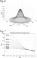
- Fig. 6 shows a representation of the Z component of a magnetic field Bz on the X-Y plane where a Hall sensor IC 16 is located, for a specific distance between a magnet 18 and Hall sensor IC, calculated using a finite element simulation.
- a casted AlNiCo cylindrical magnet with a height of 0.4mm and diameter of 0.4mm, coercivity of 44.2kA/m, is assumed.
- the distance between the Hall sensor IC plane and the center of the magnet, Zd is assumed to be 0.5mm.
- Bz has a bell shape with rotational symmetry.
- a family of parameters for varied Zd over the AF stroke can be predetermined by characterization.
- the parameters as functions of Zd can be stored in the memory of the Hall sensor IC 16 as a look-up table or parametric functions.
- the bell-shape result of the simulation shown in Figs. 6 and 7 is merely one of many possibilities, and a different shape can be obtained if a different configuration of the Hall sensors is used, a different material for the magnet is used, a different shape, size, distance to the Hall sensor IC plane is used, or if any other relevant parameter is changed. It should thus be clear for the skilled person that other 3D functions or profiles could be obtained, which could be approximated by other mathematical functions different from the Gaussian function.
- the top of the bell-shape In order to detect the Z position of the magnet 18 (thus of the lens 14), the top of the bell-shape needs to be defined. Once knowing the Z position, a corresponding bell-shaped Bz surface can be determined. Further, to detect X-Y positions of the magnet, at least three Bz values on the corresponding bell-shaped surface need to be determined.
- the radius of the geometrical shape that the Hall sensors form is preferably equal to the distance from the center to the middle of the slope of the Gaussian profiles, as such radius covers the most accurate detection range for the movement of the magnet, because it provides values for the absolute magnetic field large enough (larger than a predetermined threshold) and it provides a large enough gradient of the magnetic field (larger than a predetermined threshold).
- the radius is preferably about 0.18-0.22 mm.
- the lens position determination can be done in several steps.
- Step 1 the Z position of the magnet 18 can be deduced from the height of the top of the 3D function (the bell-shaped surface). Since the top of the bell-shaped surface is not known and cannot be determined directly, as a first step, the Z position can be estimated by taking the common-mode signal (sum or average of signals) of all the four Hall sensors (17-1, 17-2, 17-3, 17-4). The common-mode signal can then be compared with predefined information stored in the memory.
- Fig. 8 (A and B) shows the Bz averaged over the four sensors (common-mode signal) and calculated for different Z-positions (Zd).
- the averaged Bz is calculated for all positions of the magnet (or lens) over the X-Y plane, forming a common-mode Bz surface. This calculation may be made during the design process and the results or information required to obtain the results is stored in the memory, so that when the common-mode signal is obtained from the Bz measured by the Hall sensors, the result of the measurement can be compared with the stored information and the Z position can be derived.
- Figs. 8A and 8B represent the same information from different perspectives. In general, the Bz surfaces at different Zd are quite flat and separated, which means that the common-mode signal can be used to estimate Zd, regardless of the magnet position in the X-Y plane. That is why the common-mode signal method is appropriate.
- the estimate is based on calibrated characteristic of the Hall sensors. Simulations showed that the separation between Bz surfaces can be possible with minimum 6 ⁇ m separation in Zd. That means that using the common-mode signal, the Z-position can be estimated with an accuracy of 6 ⁇ m.
- Step 2 once the Z position is known, a corresponding mathematical function that describes the 3D profile of a Bz surface can be identified using a look-up table or predefined parametric functions stored in the memory of the Hall sensor IC.
- the mathematical function corresponds to a Gaussian function
- the 3D profile corresponds to the bell-shaped surface.
- a combination of at least three points can determine its X-Y position.
- Fig. 9 shows values of Bz at four sensors (marked as black dots) on the bell-shaped surface as the magnet is displaced 0.1mm and at angle 30 degrees from center in the polar coordinate system.
- the X-Y position may be determined by applying a numerical method such as the nonlinear least square solver.
- a step 4 may be performed in which the step 2 can be repeated to obtain an even more precise X-Y position.
- step 3 and step 4 may be repeated for a number of times to further refine X, Y, and Z, until the obtained accuracy reaches a specific threshold.
- step 3 sufficient accuracy may already be achieved.
- the example of the first embodiment shown above uses specific methods, it should be noted that other methods than the common-mode signal and/or the non-linear least squares solver could be used.
- another method would be to use a machine learning technique to determine the 3D position of the magnet 18 based on the at least three Hall sensor readings. In this case the values of all X, Y and Z can be determined in one go. These readings serve as features, or inputs for the machine learning algorithm. Prior to being deployed in the application, the algorithm would need to be trained with all possible 3D positions. Examples of machine learning algorithms which may be used in this case to predict continuous values are decision trees, neural networks, K-nearest neighbors, or the like.
- Fig. 10 depicts a schematic configuration of a Hall sensor IC for a camera system according to a second embodiment of the present invention.
- the second embodiment is essentially identical to the first embodiment, and the description provided for the first embodiment applies for the most part in a similar way for the second embodiment.
- the second embodiment can also be implemented with at least three Hall sensors. The only difference is that in the second embodiment all the Hall sensors (17-1, 17-2, 17-3, 17-4) in the Hall sensor IC are Hall sensors with vertical Hall plates. The directions of sensitivity of the Hall sensors are in-plane and can be arranged radially as shown by double-head arrows in Fig. 10 .
- Br the in-plane component of the B field at each sensor location can be measured. Using values of Br of the sensors, the lens position in X, Y, Z can be obtained in a similar way as described for the first embodiment. It should be evident for the skilled person that because the measured magnetic field component is different from the first embodiment, a different 3D function shape may be obtained by simulation.
- Fig. 11 depicts a schematic configuration of a Hall sensor IC for a camera system according to a third embodiment of the present invention.
- a combination of Hall sensors with horizontal and vertical Hall plates can be made on a single silicon IC or die.
- Reference number 20-1 in Fig. 11 refers to the direction of sensitivity being perpendicular to the IC plane (for horizontal Hall plates), and reference number 20-2 in Fig. 11 refers to the direction of sensitivity being parallel to the IC plane (for vertical Hall plates).
- Bz can be measured at the location of the horizontal Hall sensors
- Br can be measured at the location of the vertical Hall sensors, and the results can be processed and combined to obtain the X, Y and Z position of the lens.
- the Hall sensor IC of the third embodiment comprises two sets of sensors, each containing at least three Hall sensors, but preferably four Hall sensors. Each of the sets corresponds to each of the two functions.
- other configurations can be used where there are at least three sensors.
- the sensors can be a mixture of horizontal and vertical Hall sensors, such as one horizontal and two vertical, or two horizontal and one vertical.
- a camera system may comprise at least three Hall sensors in the Hall sensor IC as explained before.
- the Hall sensors may be configured to be enabled and disabled, that is, switched on/off, by the controlling unit depending on system specifications, and the algorithm residing in the firmware of the system can also be switched accordingly.
- only one Hall sensor could be enabled or switched on so as to be used to determine the position of the lens in the Z direction only, whereas the other sensors are switched off to save power.
- two Hall sensors could be enabled instead of one, to determine the lens position in the Z direction.
- two of the at least three Hall sensors may be enabled to determine the lens position in the Z direction.
- the two Hall sensors may be in a differential configuration. The remaining Hall sensors may be switched off.
- the magnet is arranged such that its magnetization is perpendicular to the Hall sensor IC plane.
- the control unit may control which Hall sensors are enabled and disabled.
- the invention may also comprise a camera system comprising a plurality of Hall sensor ICs 16, each comprising at least three Hall sensors 17. This allows to perform measurements in different directions with different ICs and therefore decouple the detection of for example Z and X-Y, thereby making the detection more accurate and faster.
Landscapes
- Engineering & Computer Science (AREA)
- Health & Medical Sciences (AREA)
- Biomedical Technology (AREA)
- General Health & Medical Sciences (AREA)
- Multimedia (AREA)
- Signal Processing (AREA)
- Physics & Mathematics (AREA)
- General Physics & Mathematics (AREA)
- Measurement Of Length, Angles, Or The Like Using Electric Or Magnetic Means (AREA)
Claims (12)
- - Circuit intégré (CI) à capteurs à effet Hall (16) pour un système de caméra (10), le CI à capteurs à effet Hall comprenant :au moins trois capteurs à effet Hall (17) espacés les uns des autres dans une configuration non alignée, et configurés pour mesurer un champ magnétique généré par un aimant (18) à une position de l'aimant disposé dans le système de caméra, l'aimant (18) étant disposé à l'intérieur d'un boîtier et faisant face au CI à capteurs à effet Hall, et l'un du CI à capteurs à effet Hall (16) et de l'aimant (18) étant disposé sur un premier côté intérieur du boîtier (12) et l'autre du CI à capteurs à effet Hall (16) et de l'aimant (18) étant disposé sur un premier côté d'un module d'objectif (14) faisant face au premier côté intérieur du boîtier ;une unité de commande configurée pour commander le CI à capteurs à effet Hall (16) afin de déterminer la position de l'aimant (18) sur la base d'une combinaison des champs magnétiques mesurés par les au moins trois capteurs à effet Hall (17) à chaque position des au moins trois capteurs à effet Hall (17), la combinaison étant basée sur chaque position des au moins trois capteurs à effet Hall (17) ; etune mémoire en communication avec le CI à capteurs à effet Hall (16) configurée pour stocker des informations nécessaires pour obtenir la position de l'aimant (18), l'unité de commande déterminant la position de l'aimant sur la base de la combinaison des champs magnétiques mesurés par les au moins trois capteurs à effet Hall (17),une distance entre un bord de l'aimant (18) le plus proche du CI à capteurs à effet Hall (16) et le CI à capteurs à effet Hall n'est pas supérieure à 2 millimètres.
- - Circuit intégré à capteurs à effet Hall (16) selon la revendication 1, dans lequel les au moins trois capteurs à effet Hall (17) sont disposés à l'intérieur du CI à capteurs à effet Hall en formant une configuration géométrique les uns par rapport aux autres avec une symétrie centrale ou une symétrie axiale.
- - Circuit intégré à capteurs à effet Hall (16) selon l'une quelconque des revendications 1 et 2, dans lequel les au moins trois capteurs à effet Hall (17) sont espacés les uns des autres de manière égale.
- - Circuit intégré à capteurs à effet Hall (16) selon l'une quelconque des revendications 1 à 3, dans lequel chacun des au moins trois capteurs à effet Hall (17) est configuré pour être activé et désactivé individuellement.
- - Circuit intégré à capteurs à effet Hall (16) selon l'une quelconque des revendications 1 à 4, comprenant quatre capteurs à effet Hall (17) disposés à l'intérieur du CI à capteurs à effet Hall en formant une configuration circulaire ou une configuration carrée.
- - Circuit intégré à capteurs à effet Hall (16) selon la revendication 5, dans lequel un rayon d'une forme géométrique formée par les quatre capteurs à effet Hall (17) est égal à une distance d'un centre de la forme géométrique à un milieu d'une pente d'un profil gaussien du champ magnétique de l'aimant (18).
- - Circuit intégré à capteurs à effet Hall (16) selon l'une quelconque des revendications 1 à 6, configuré pour être intégré dans un autre circuit intégré (CI) compris dans le système de caméra (10), l'autre CI faisant partie d'une liste comprenant : un porte-objectif, un contrôleur de moteur, un capteur d'image, un contrôleur de capteur d'image, un processeur d'image, ou tout autre CI présent dans le système de caméra.
- - Système de caméra (10) comprenant :un boîtier (12) ;un module d'objectif (14) disposé à l'intérieur du boîtier ;un circuit intégré (CI) à capteurs à effet Hall (16) selon l'une quelconque des revendications 1 à 6 et disposé à l'intérieur du boîtier ; etun aimant (18) disposé à l'intérieur du boîtier et faisant face au CI à capteurs à effet Hall,l'un du CI à capteurs à effet Hall (16) et de l'aimant (18) étant disposé sur un premier côté intérieur du boîtier (12) et l'autre du CI à capteurs à effet Hall (16) et de l'aimant (18) étant disposé sur un premier côté du module d'objectif (14) faisant face au premier côté intérieur du boîtier.
- - Système de caméra selon la revendication 8, dans lequel une distance entre un bord de l'aimant (18) le plus proche du CI à capteurs à effet Hall (16) et le CI à capteurs à effet Hall n'est pas supérieure à 1 millimètre, et de préférence pas supérieure à 0,5 millimètre.
- - Système de caméra selon la revendication 8 ou 9, dans lequel les au moins trois capteurs à effet Hall (17) du CI à capteurs à effet Hall sont tous des capteurs à effet Hall avec des plaques à effet Hall horizontales, et l'aimant (18) est magnétisé dans une direction perpendiculaire à un plan du CI à capteurs à effet Hall.
- - Procédé pour déterminer une position d'un module d'objectif (14) disposé à l'intérieur d'un système de caméra (12), comprenant :- mesurer, par chacun des au moins trois capteurs à effet Hall (17) du CI à capteurs à effet Hall (16) selon l'une quelconque des revendications 1 à 7, un champ magnétique généré par un aimant à une position de l'aimant (18) disposé à l'intérieur du système de caméra, et- combiner le champ magnétique mesuré par chacun des au moins trois capteurs à effet Hall (17) pour déterminer la position de l'aimant (18),l'un du CI à capteurs à effet Hall (16) et de l'aimant (18) étant disposé sur un premier côté intérieur d'un boîtier (12) du système de caméra et l'autre du CI à capteurs à effet Hall (16) et de l'aimant (18) étant disposé sur un premier côté du module d'objectif (14) faisant face au premier côté intérieur du boîtier, pour déterminer la position de l'aimant (18) le procédé comprenant comparer à des informations prédéfinies stockées dans une table de recherche le champ magnétique mesuré combiné, une distance entre un bord de l'aimant (18) le plus proche du CI à capteurs à effet Hall (16) et le CI à capteurs à effet Hall n'étant pas supérieure à 2 millimètres.
- - Procédé selon la revendication 11, dans lequel la position de l'aimant est une position tridimensionnelle (3D) et, pour déterminer la position 3D de l'aimant (18), le procédé comprend utiliser des informations prédéfinies stockées sous la forme d'au moins une fonction paramétrique pour transformer une pluralité de champs magnétiques mesurés par les au moins trois capteurs à effet Hall en la position 3D de l'aimant (18).
Priority Applications (2)
| Application Number | Priority Date | Filing Date | Title |
|---|---|---|---|
| EP20194083.0A EP3964800B1 (fr) | 2020-09-02 | 2020-09-02 | Détection de position triaxiale pour systèmes de caméra utilisant des capteurs à effet hall |
| CN202111026923.0A CN113709452B (zh) | 2020-09-02 | 2021-09-02 | 使用霍尔传感器对相机系统进行三轴位置感测 |
Applications Claiming Priority (1)
| Application Number | Priority Date | Filing Date | Title |
|---|---|---|---|
| EP20194083.0A EP3964800B1 (fr) | 2020-09-02 | 2020-09-02 | Détection de position triaxiale pour systèmes de caméra utilisant des capteurs à effet hall |
Publications (2)
| Publication Number | Publication Date |
|---|---|
| EP3964800A1 EP3964800A1 (fr) | 2022-03-09 |
| EP3964800B1 true EP3964800B1 (fr) | 2024-12-04 |
Family
ID=72340272
Family Applications (1)
| Application Number | Title | Priority Date | Filing Date |
|---|---|---|---|
| EP20194083.0A Active EP3964800B1 (fr) | 2020-09-02 | 2020-09-02 | Détection de position triaxiale pour systèmes de caméra utilisant des capteurs à effet hall |
Country Status (2)
| Country | Link |
|---|---|
| EP (1) | EP3964800B1 (fr) |
| CN (1) | CN113709452B (fr) |
Families Citing this family (5)
| Publication number | Priority date | Publication date | Assignee | Title |
|---|---|---|---|---|
| JP7844671B2 (ja) * | 2022-05-06 | 2026-04-13 | エフ ホフマン-ラ ロッシュ アクチェン ゲゼルシャフト | 接続モジュールの相対位置を追跡するための位置追跡システム及び方法 |
| CN114587574B (zh) * | 2022-05-09 | 2022-08-12 | 深圳市艾泉科技有限公司 | 治疗装置及皮肤处理设备 |
| CN117055232B (zh) * | 2023-10-13 | 2024-01-02 | 北京极溯光学科技有限公司 | 眼镜调节装置以及vr眼镜 |
| CN120761932B (zh) * | 2025-09-03 | 2026-03-20 | 苏州矩阵光电有限公司 | 一种3d霍尔芯片及阵列芯片 |
| CN121025941A (zh) * | 2025-09-17 | 2025-11-28 | 北京靖宏云泰科技有限公司 | 一种基于磁感应通信的建筑预埋件状态监测方法 |
Family Cites Families (10)
| Publication number | Priority date | Publication date | Assignee | Title |
|---|---|---|---|---|
| KR101300353B1 (ko) * | 2011-12-22 | 2013-08-28 | 삼성전기주식회사 | 손떨림 보정장치 |
| DE102012002204B4 (de) * | 2012-01-27 | 2019-06-13 | Avago Technologies International Sales Pte. Limited | Magnetfeldsensor |
| WO2013183270A1 (fr) * | 2012-06-07 | 2013-12-12 | 旭化成エレクトロニクス株式会社 | Dispositif de détection de position |
| KR101929590B1 (ko) * | 2013-12-05 | 2019-03-13 | 매그나칩 반도체 유한회사 | 3차원 구조로 배치된 복수의 홀 센서를 이용한 센싱 시스템 및 이를 이용한 장치 |
| US9591221B2 (en) * | 2014-01-08 | 2017-03-07 | Apple Inc. | Magnetic camera component mounting in cameras |
| JP6513903B2 (ja) * | 2014-03-31 | 2019-05-15 | 旭化成エレクトロニクス株式会社 | カメラモジュール及びその光学要素の位置制御方法並びに携帯機器 |
| CN106687846B (zh) * | 2014-07-11 | 2020-02-28 | 三美电机株式会社 | 透镜驱动装置、摄像机模块以及摄像机搭载装置 |
| KR102550824B1 (ko) * | 2015-10-26 | 2023-07-04 | 엘지이노텍 주식회사 | 렌즈 구동 장치, 카메라 모듈 및 광학기기 |
| DE102016108846B4 (de) * | 2016-05-12 | 2024-05-08 | Infineon Technologies Ag | Winkelsensoranordnung und Verfahren für die Winkelsensoranordnung |
| KR102560790B1 (ko) * | 2016-07-29 | 2023-07-28 | 엘지이노텍 주식회사 | 듀얼 카메라 모듈 및 광학기기 |
-
2020
- 2020-09-02 EP EP20194083.0A patent/EP3964800B1/fr active Active
-
2021
- 2021-09-02 CN CN202111026923.0A patent/CN113709452B/zh active Active
Also Published As
| Publication number | Publication date |
|---|---|
| CN113709452B (zh) | 2023-01-24 |
| EP3964800A1 (fr) | 2022-03-09 |
| CN113709452A (zh) | 2021-11-26 |
Similar Documents
| Publication | Publication Date | Title |
|---|---|---|
| EP3964800B1 (fr) | Détection de position triaxiale pour systèmes de caméra utilisant des capteurs à effet hall | |
| CN107340668B (zh) | 双镜头照相系统 | |
| CN207965330U (zh) | 动圈式避磁闭回路自动对焦摄像模块 | |
| JP4915996B2 (ja) | センサ・モジュール、補正方法、プログラム及び記録媒体 | |
| WO2015068061A2 (fr) | Détection de position basée sur l'inductance dans un actionneur de caméra numérique | |
| JP2009069148A (ja) | 磁界を測定する測定装置 | |
| US10359597B2 (en) | Optical system | |
| US11150109B2 (en) | Displacement detecting device and continuously variable transmission device | |
| US10690880B2 (en) | Optical element driving mechanism | |
| CN108267829B (zh) | 光学元件驱动机构 | |
| US20150145506A1 (en) | Magnetic sensor | |
| US11567289B2 (en) | Optical element drive device | |
| KR101438233B1 (ko) | 위치 검출 장치 및 광학 기기 | |
| US20040021458A1 (en) | Displacement sensor | |
| US11243370B2 (en) | Optical system | |
| US12174045B2 (en) | Position detection unit, lens module, and imaging apparatus | |
| JP2009230025A (ja) | コイル駆動ユニット、ブレ補正機構および撮像装置 | |
| CN212363192U (zh) | 倾斜检测装置、照相机装置以及电子设备 | |
| US10215588B2 (en) | Position detecting device and structure for using position detecting device | |
| US12212850B2 (en) | Sensor shifting actuator | |
| KR101298845B1 (ko) | 오브젝트에 구비된 지자기 센서의 방위각 보정 방법 및 장치 | |
| US20230090679A1 (en) | Apparatus and method for calibrating a magnetic sensor system using an inhomogeneous magnetic field source | |
| US20240405643A1 (en) | Position detection system for use in motors | |
| US20160377453A1 (en) | Position detection device, control method, and storage medium | |
| JP2007303864A (ja) | 磁界センサおよび磁界センシングの方法 |
Legal Events
| Date | Code | Title | Description |
|---|---|---|---|
| PUAI | Public reference made under article 153(3) epc to a published international application that has entered the european phase |
Free format text: ORIGINAL CODE: 0009012 |
|
| STAA | Information on the status of an ep patent application or granted ep patent |
Free format text: STATUS: REQUEST FOR EXAMINATION WAS MADE |
|
| 17P | Request for examination filed |
Effective date: 20211104 |
|
| AK | Designated contracting states |
Kind code of ref document: A1 Designated state(s): AL AT BE BG CH CY CZ DE DK EE ES FI FR GB GR HR HU IE IS IT LI LT LU LV MC MK MT NL NO PL PT RO RS SE SI SK SM TR |
|
| STAA | Information on the status of an ep patent application or granted ep patent |
Free format text: STATUS: EXAMINATION IS IN PROGRESS |
|
| 17Q | First examination report despatched |
Effective date: 20220922 |
|
| GRAP | Despatch of communication of intention to grant a patent |
Free format text: ORIGINAL CODE: EPIDOSNIGR1 |
|
| STAA | Information on the status of an ep patent application or granted ep patent |
Free format text: STATUS: GRANT OF PATENT IS INTENDED |
|
| INTG | Intention to grant announced |
Effective date: 20240708 |
|
| GRAS | Grant fee paid |
Free format text: ORIGINAL CODE: EPIDOSNIGR3 |
|
| GRAA | (expected) grant |
Free format text: ORIGINAL CODE: 0009210 |
|
| STAA | Information on the status of an ep patent application or granted ep patent |
Free format text: STATUS: THE PATENT HAS BEEN GRANTED |
|
| AK | Designated contracting states |
Kind code of ref document: B1 Designated state(s): AL AT BE BG CH CY CZ DE DK EE ES FI FR GB GR HR HU IE IS IT LI LT LU LV MC MK MT NL NO PL PT RO RS SE SI SK SM TR |
|
| REG | Reference to a national code |
Ref country code: CH Ref legal event code: EP |
|
| REG | Reference to a national code |
Ref country code: IE Ref legal event code: FG4D |
|
| REG | Reference to a national code |
Ref country code: DE Ref legal event code: R096 Ref document number: 602020042384 Country of ref document: DE |
|
| REG | Reference to a national code |
Ref country code: LT Ref legal event code: MG9D |
|
| REG | Reference to a national code |
Ref country code: NL Ref legal event code: MP Effective date: 20241204 |
|
| PG25 | Lapsed in a contracting state [announced via postgrant information from national office to epo] |
Ref country code: HR Free format text: LAPSE BECAUSE OF FAILURE TO SUBMIT A TRANSLATION OF THE DESCRIPTION OR TO PAY THE FEE WITHIN THE PRESCRIBED TIME-LIMIT Effective date: 20241204 |
|
| PG25 | Lapsed in a contracting state [announced via postgrant information from national office to epo] |
Ref country code: FI Free format text: LAPSE BECAUSE OF FAILURE TO SUBMIT A TRANSLATION OF THE DESCRIPTION OR TO PAY THE FEE WITHIN THE PRESCRIBED TIME-LIMIT Effective date: 20241204 |
|
| PG25 | Lapsed in a contracting state [announced via postgrant information from national office to epo] |
Ref country code: BG Free format text: LAPSE BECAUSE OF FAILURE TO SUBMIT A TRANSLATION OF THE DESCRIPTION OR TO PAY THE FEE WITHIN THE PRESCRIBED TIME-LIMIT Effective date: 20241204 |
|
| PG25 | Lapsed in a contracting state [announced via postgrant information from national office to epo] |
Ref country code: ES Free format text: LAPSE BECAUSE OF FAILURE TO SUBMIT A TRANSLATION OF THE DESCRIPTION OR TO PAY THE FEE WITHIN THE PRESCRIBED TIME-LIMIT Effective date: 20241204 |
|
| PG25 | Lapsed in a contracting state [announced via postgrant information from national office to epo] |
Ref country code: NO Free format text: LAPSE BECAUSE OF FAILURE TO SUBMIT A TRANSLATION OF THE DESCRIPTION OR TO PAY THE FEE WITHIN THE PRESCRIBED TIME-LIMIT Effective date: 20250304 |
|
| PG25 | Lapsed in a contracting state [announced via postgrant information from national office to epo] |
Ref country code: LV Free format text: LAPSE BECAUSE OF FAILURE TO SUBMIT A TRANSLATION OF THE DESCRIPTION OR TO PAY THE FEE WITHIN THE PRESCRIBED TIME-LIMIT Effective date: 20241204 Ref country code: GR Free format text: LAPSE BECAUSE OF FAILURE TO SUBMIT A TRANSLATION OF THE DESCRIPTION OR TO PAY THE FEE WITHIN THE PRESCRIBED TIME-LIMIT Effective date: 20250305 |
|
| PG25 | Lapsed in a contracting state [announced via postgrant information from national office to epo] |
Ref country code: RS Free format text: LAPSE BECAUSE OF FAILURE TO SUBMIT A TRANSLATION OF THE DESCRIPTION OR TO PAY THE FEE WITHIN THE PRESCRIBED TIME-LIMIT Effective date: 20250304 |
|
| PG25 | Lapsed in a contracting state [announced via postgrant information from national office to epo] |
Ref country code: NL Free format text: LAPSE BECAUSE OF FAILURE TO SUBMIT A TRANSLATION OF THE DESCRIPTION OR TO PAY THE FEE WITHIN THE PRESCRIBED TIME-LIMIT Effective date: 20241204 |
|
| REG | Reference to a national code |
Ref country code: AT Ref legal event code: MK05 Ref document number: 1748603 Country of ref document: AT Kind code of ref document: T Effective date: 20241204 |
|
| PG25 | Lapsed in a contracting state [announced via postgrant information from national office to epo] |
Ref country code: SM Free format text: LAPSE BECAUSE OF FAILURE TO SUBMIT A TRANSLATION OF THE DESCRIPTION OR TO PAY THE FEE WITHIN THE PRESCRIBED TIME-LIMIT Effective date: 20241204 |
|
| PG25 | Lapsed in a contracting state [announced via postgrant information from national office to epo] |
Ref country code: PL Free format text: LAPSE BECAUSE OF FAILURE TO SUBMIT A TRANSLATION OF THE DESCRIPTION OR TO PAY THE FEE WITHIN THE PRESCRIBED TIME-LIMIT Effective date: 20241204 |
|
| PG25 | Lapsed in a contracting state [announced via postgrant information from national office to epo] |
Ref country code: IS Free format text: LAPSE BECAUSE OF FAILURE TO SUBMIT A TRANSLATION OF THE DESCRIPTION OR TO PAY THE FEE WITHIN THE PRESCRIBED TIME-LIMIT Effective date: 20250404 |
|
| PG25 | Lapsed in a contracting state [announced via postgrant information from national office to epo] |
Ref country code: PT Free format text: LAPSE BECAUSE OF FAILURE TO SUBMIT A TRANSLATION OF THE DESCRIPTION OR TO PAY THE FEE WITHIN THE PRESCRIBED TIME-LIMIT Effective date: 20250404 |
|
| PG25 | Lapsed in a contracting state [announced via postgrant information from national office to epo] |
Ref country code: EE Free format text: LAPSE BECAUSE OF FAILURE TO SUBMIT A TRANSLATION OF THE DESCRIPTION OR TO PAY THE FEE WITHIN THE PRESCRIBED TIME-LIMIT Effective date: 20241204 |
|
| PG25 | Lapsed in a contracting state [announced via postgrant information from national office to epo] |
Ref country code: AT Free format text: LAPSE BECAUSE OF FAILURE TO SUBMIT A TRANSLATION OF THE DESCRIPTION OR TO PAY THE FEE WITHIN THE PRESCRIBED TIME-LIMIT Effective date: 20241204 Ref country code: RO Free format text: LAPSE BECAUSE OF FAILURE TO SUBMIT A TRANSLATION OF THE DESCRIPTION OR TO PAY THE FEE WITHIN THE PRESCRIBED TIME-LIMIT Effective date: 20241204 |
|
| PG25 | Lapsed in a contracting state [announced via postgrant information from national office to epo] |
Ref country code: SK Free format text: LAPSE BECAUSE OF FAILURE TO SUBMIT A TRANSLATION OF THE DESCRIPTION OR TO PAY THE FEE WITHIN THE PRESCRIBED TIME-LIMIT Effective date: 20241204 |
|
| PG25 | Lapsed in a contracting state [announced via postgrant information from national office to epo] |
Ref country code: CZ Free format text: LAPSE BECAUSE OF FAILURE TO SUBMIT A TRANSLATION OF THE DESCRIPTION OR TO PAY THE FEE WITHIN THE PRESCRIBED TIME-LIMIT Effective date: 20241204 |
|
| PG25 | Lapsed in a contracting state [announced via postgrant information from national office to epo] |
Ref country code: IT Free format text: LAPSE BECAUSE OF FAILURE TO SUBMIT A TRANSLATION OF THE DESCRIPTION OR TO PAY THE FEE WITHIN THE PRESCRIBED TIME-LIMIT Effective date: 20241204 |
|
| REG | Reference to a national code |
Ref country code: DE Ref legal event code: R097 Ref document number: 602020042384 Country of ref document: DE |
|
| PG25 | Lapsed in a contracting state [announced via postgrant information from national office to epo] |
Ref country code: SE Free format text: LAPSE BECAUSE OF FAILURE TO SUBMIT A TRANSLATION OF THE DESCRIPTION OR TO PAY THE FEE WITHIN THE PRESCRIBED TIME-LIMIT Effective date: 20241204 |
|
| PG25 | Lapsed in a contracting state [announced via postgrant information from national office to epo] |
Ref country code: DK Free format text: LAPSE BECAUSE OF FAILURE TO SUBMIT A TRANSLATION OF THE DESCRIPTION OR TO PAY THE FEE WITHIN THE PRESCRIBED TIME-LIMIT Effective date: 20241204 |
|
| PGFP | Annual fee paid to national office [announced via postgrant information from national office to epo] |
Ref country code: DE Payment date: 20250827 Year of fee payment: 6 |
|
| PLBE | No opposition filed within time limit |
Free format text: ORIGINAL CODE: 0009261 |
|
| STAA | Information on the status of an ep patent application or granted ep patent |
Free format text: STATUS: NO OPPOSITION FILED WITHIN TIME LIMIT |
|
| PGFP | Annual fee paid to national office [announced via postgrant information from national office to epo] |
Ref country code: GB Payment date: 20250821 Year of fee payment: 6 |
|
| 26N | No opposition filed |
Effective date: 20250905 |