EP3964832A1 - Procédé de mesure et agencement de mesure destinés à la suppression des interférences d'un signal de réception d'un transducteur emat - Google Patents
Procédé de mesure et agencement de mesure destinés à la suppression des interférences d'un signal de réception d'un transducteur emat Download PDFInfo
- Publication number
- EP3964832A1 EP3964832A1 EP21194073.9A EP21194073A EP3964832A1 EP 3964832 A1 EP3964832 A1 EP 3964832A1 EP 21194073 A EP21194073 A EP 21194073A EP 3964832 A1 EP3964832 A1 EP 3964832A1
- Authority
- EP
- European Patent Office
- Prior art keywords
- received signal
- signal
- measuring arrangement
- interference
- emat
- Prior art date
- Legal status (The legal status is an assumption and is not a legal conclusion. Google has not performed a legal analysis and makes no representation as to the accuracy of the status listed.)
- Pending
Links
Images




Classifications
-
- G—PHYSICS
- G01—MEASURING; TESTING
- G01N—INVESTIGATING OR ANALYSING MATERIALS BY DETERMINING THEIR CHEMICAL OR PHYSICAL PROPERTIES
- G01N29/00—Investigating or analysing materials by the use of ultrasonic, sonic or infrasonic waves; Visualisation of the interior of objects by transmitting ultrasonic or sonic waves through the object
- G01N29/22—Details, e.g. general constructional or apparatus details
- G01N29/32—Arrangements for suppressing undesired influences, e.g. temperature or pressure variations, compensating for signal noise
-
- G—PHYSICS
- G01—MEASURING; TESTING
- G01F—MEASURING VOLUME, VOLUME FLOW, MASS FLOW OR LIQUID LEVEL; METERING BY VOLUME
- G01F1/00—Measuring the volume flow or mass flow of fluid or fluent solid material wherein the fluid passes through a meter in a continuous flow
- G01F1/66—Measuring the volume flow or mass flow of fluid or fluent solid material wherein the fluid passes through a meter in a continuous flow by measuring frequency, phase shift or propagation time of electromagnetic or other waves, e.g. using ultrasonic flowmeters
-
- G—PHYSICS
- G01—MEASURING; TESTING
- G01F—MEASURING VOLUME, VOLUME FLOW, MASS FLOW OR LIQUID LEVEL; METERING BY VOLUME
- G01F1/00—Measuring the volume flow or mass flow of fluid or fluent solid material wherein the fluid passes through a meter in a continuous flow
- G01F1/66—Measuring the volume flow or mass flow of fluid or fluent solid material wherein the fluid passes through a meter in a continuous flow by measuring frequency, phase shift or propagation time of electromagnetic or other waves, e.g. using ultrasonic flowmeters
- G01F1/667—Arrangements of transducers for ultrasonic flowmeters; Circuits for operating ultrasonic flowmeters
-
- G—PHYSICS
- G01—MEASURING; TESTING
- G01N—INVESTIGATING OR ANALYSING MATERIALS BY DETERMINING THEIR CHEMICAL OR PHYSICAL PROPERTIES
- G01N29/00—Investigating or analysing materials by the use of ultrasonic, sonic or infrasonic waves; Visualisation of the interior of objects by transmitting ultrasonic or sonic waves through the object
- G01N29/22—Details, e.g. general constructional or apparatus details
- G01N29/24—Probes
- G01N29/2412—Probes using the magnetostrictive properties of the material to be examined, e.g. electromagnetic acoustic transducers [EMAT]
-
- G—PHYSICS
- G01—MEASURING; TESTING
- G01N—INVESTIGATING OR ANALYSING MATERIALS BY DETERMINING THEIR CHEMICAL OR PHYSICAL PROPERTIES
- G01N29/00—Investigating or analysing materials by the use of ultrasonic, sonic or infrasonic waves; Visualisation of the interior of objects by transmitting ultrasonic or sonic waves through the object
- G01N29/44—Processing the detected response signal, e.g. electronic circuits specially adapted therefor
- G01N29/4463—Signal correction, e.g. distance amplitude correction [DAC], distance gain size [DGS], noise filtering
-
- G—PHYSICS
- G01—MEASURING; TESTING
- G01N—INVESTIGATING OR ANALYSING MATERIALS BY DETERMINING THEIR CHEMICAL OR PHYSICAL PROPERTIES
- G01N29/00—Investigating or analysing materials by the use of ultrasonic, sonic or infrasonic waves; Visualisation of the interior of objects by transmitting ultrasonic or sonic waves through the object
- G01N29/44—Processing the detected response signal, e.g. electronic circuits specially adapted therefor
- G01N29/50—Processing the detected response signal, e.g. electronic circuits specially adapted therefor using auto-correlation techniques or cross-correlation techniques
-
- G—PHYSICS
- G01—MEASURING; TESTING
- G01R—MEASURING ELECTRIC VARIABLES; MEASURING MAGNETIC VARIABLES
- G01R31/00—Arrangements for testing electric properties; Arrangements for locating electric faults; Arrangements for electrical testing characterised by what is being tested not provided for elsewhere
- G01R31/001—Measuring interference from external sources to, or emission from, the device under test, e.g. EMC, EMI, EMP or ESD testing
- G01R31/002—Measuring interference from external sources to, or emission from, the device under test, e.g. EMC, EMI, EMP or ESD testing where the device under test is an electronic circuit
-
- H—ELECTRICITY
- H04—ELECTRIC COMMUNICATION TECHNIQUE
- H04B—TRANSMISSION
- H04B11/00—Transmission systems employing ultrasonic, sonic or infrasonic waves
Definitions
- the invention relates to a measuring method on an electrically conductive object, in particular on a pipeline, with a first ultrasonic wave being transmitted by means of a first EMAT transmitter transducer of a measuring arrangement positioned on or near a surface of the object and having a first transmitter transducer induction coil having at least one conductor track the object is generated and a first EMAT receiving transducer of the measuring arrangement positioned on or near the surface of the object, which has a first receiving transducer induction coil having at least one conductor track, detects a first received signal, the first received signal being at least partially composed of the first ultrasonic wave , which has propagated through at least part of the object, comprises a resultant first ultrasonic signal and a first electromagnetic interference signal. Furthermore, the invention relates to a measuring arrangement for carrying out such a measuring method.
- EMAT converters are used in various branches of industry for non-destructive testing and measuring processes.
- One advantage of this technology is that acoustic waves can be generated in a conductive object without contact, ie without acoustic coupling by means of a coupling medium.
- EMAT converters are particularly suitable for use under harsh operating conditions, for example when the object is exposed to particularly high or low temperatures.
- EMAT converters The functioning of EMAT converters is based on the interaction of an induction coil with a magnet.
- the magnet which can be a permanent magnet or an electromagnet, magnetizes part of the surface of the conductive object.
- the induction coil When the induction coil is driven by an alternating current, it creates an alternating current magnetic field, which generates eddy currents in the conducting object, which in turn interact with the magnet's magnetic field.
- the magnetic field can be a static magnetic field from a permanent magnet or a quasi-static magnetic field from an electromagnet driven at a much lower frequency than the induction coil.
- an ultrasonic wave is generated in the object, e.g. in the form of a single ultrasonic pulse, i.e. a wave packet comprising several, for example sinusoidal, oscillations, or in the form of a sequence of ultrasonic pulses, which is generally referred to as a "pulse burst".
- the ultrasonic wave which has propagated through at least part of the object, interacts with the static or quasi-static magnetic field of the EMAT receiving transducer and generates eddy currents in the object, which in turn generate an alternating magnetic field , which induces an ultrasonic signal in the induction coil.
- This ultrasonic signal can be used to determine information about the object, such as stress corrosion cracks or defects in a coating of the object, and possibly also properties of a medium flowing through the object, for example its flow rate.
- the EMAT transducers are positioned so close to a surface of the object that the fields of the EMAT transducers still act on the object or a wall of the object, i.e. generate ultrasonic waves there or can detect. A direct contact between the EMAT converters and the object is not necessary for this.
- electromagnetic interference signals are also coupled into the induction coil of the EMAT receiving transducer, which is usually galvanically isolated from the object being measured.
- the received signal is noisy due to these interference signals.
- interference occurs which is generated by interference sources such as motors or frequency converters and spreads through the pipeline wall over large distances.
- This interference can couple into the measuring system as interference signals.
- a potential difference between the measuring system and the object which is usually galvanically isolated from it and grounded, can also couple into the measuring system as an additional interference signal.
- the interference signals that occur lead to a deteriorated signal-to-noise ratio, so that information about the object and possibly properties of a medium flowing through the object cannot be optimally determined.
- the object of the present invention is therefore to provide an EMAT-based measurement method and an EMAT-based measurement arrangement with an improved signal-to-noise ratio.
- An additional receiving channel for the interference signal is provided by the first receiving means and the interference is thus independent of the first EMAT receiving transducer picked up again.
- the second interference signal can be used to anticipate the characteristics of the first interference signal and to filter it out of the first received signal.
- the first received signal and the second received signal are processed together in an interference suppression operation using an interference suppression means.
- the first received signal is thus at least partially suppressed, ie the ratio of ultrasonic signal to noise signal is improved in the received signal.
- An operation in which at least the first received signal and the second received signal are processed together is referred to as an interference suppression operation, whereupon the ratio of the first ultrasonic signal to the first interference signal in the first received signal improves, i.e. the proportion of the first interference signal in the first received signal decreases.
- an interference suppression operation whereupon the ratio of the first ultrasonic signal to the first interference signal in the first received signal improves, i.e. the proportion of the first interference signal in the first received signal decreases.
- a subtraction of the second received signal, possibly multiplied by a factor, from the first received signal can represent such an interference suppression operation.
- other noise reduction operations can be used as long as they meet the above definition of a noise reduction operation.
- the measuring arrangement preferably includes a control and evaluation unit which controls and reads out the EMAT converter and evaluates the received signals.
- the interference suppression means in the control and evaluation unit for example in the form of software running on the control and evaluation unit.
- the second received signal is detected by a receiving means coil of the first receiving means that is positioned on or near the surface of the object and has at least one conductor track.
- An interference signal recorded with an induction coil that is separate from the first receiving transducer induction coil is referred to below as a coil interference signal.
- both the first interference signal and the second interference signal are detected by means of an induction coil, as a result of which the interference signals are largely similar.
- a particularly reliable interference suppression operation can be achieved, for example by subtracting the second received signal from the first received signal.
- the receiving means induction coil used to detect the second received signal is at least essentially identical in construction to the first receiving transducer induction coil, e.g. has the same external dimensions and the same number of windings.
- the first interference signal and the second interference signal are largely similar, in particular almost identical, which enables an even more reliable interference suppression operation.
- the first transmitting transducer induction coil or another induction coil of the measuring arrangement that is different from the receiving transducer induction coil is used as the receiving means induction coil for detecting the second received signal.
- various transducer configurations are possible in which the distance between the receiving transducer and another transducer of the measuring arrangement is dimensioned such that when the receiving transducer records an ultrasonic signal at which no or almost no ultrasonic signal is present at the further transducer, for example at the transmitting transducer associated with the receiving transducer or also at a transducer of a further transmitter-receiver pair of the measuring arrangement.
- the induction coil of this further transducer can be used as a receiving means.
- existing components of the measuring arrangement are used to detect the second interference signal used for the interference suppression operation.
- interference suppression can be achieved in a particularly simple and cost-effective manner.
- the improved measurement method can also be easily implemented on existing systems.
- the second received signal is detected by means of a line of the measuring arrangement which is electrically conductively connected to the object or a grounded housing part of a housing protecting the measuring arrangement or is grounded in some other way as the first receiving means.
- An interference signal measured separately with such a line is referred to below as an earth interference signal.
- an interference signal that originates from a potential difference between the EMAT system and the object, which is usually grounded can be recorded separately and processed in the interference suppression operation to improve the signal-to-noise ratio. Since the ground potential is a reference point for the potential difference causing the noise, any type of grounded contact can be used as a receiving means for the purpose of separate detection of the grounding interference signal.
- the second received signal tapped off via the line is preferably coupled into a measuring line of the measuring arrangement while maintaining a galvanic isolation, in particular capacitively.
- the second interference signal can be detected without influencing the potential difference between the EMAT system and the object and thus the first interference signal, which would have negative effects on the interference suppression operation and possibly also the ultrasonic measurement itself.
- this makes the method suitable for those metrological applications in which galvanic isolation must be observed, for example due to safety regulations.
- the second received signal can be coupled in while maintaining a galvanic isolation, for example, by capacitive or inductive isolation of the measuring circuits.
- At least the first received signal and the second received signal are added to an analog and/or digital, electrical and/or electronic component or an analog and/or digital, electrical and/or electronic circuit as an interference suppression agent, in particular where the interference suppression operation includes at least a subtraction of the received signals, preferably a subtraction of the second received signal from the first received signal.
- An interference suppression means designed in this way can be implemented in a simple manner and at low cost.
- the use of a common-mode choke as an interference suppression means is particularly advantageous in this case, in which the first received signal and the second received signal are fed to the inputs of the common-mode choke and subjected to an inductive subtraction as an interference suppression operation.
- the common-mode choke has several identical windings through which the received signals flow in opposite directions, so that their magnetic fields cancel out in the core of the common-mode choke.
- the second interference signal which is largely similar to the first interference signal, in particular essentially identical, is subtracted from the first received signal, as a result of which ideally only the first ultrasonic signal remains in the first received signal.
- a data processing system can also be used as interference suppression means, to which the first received signal and the second received signal are supplied.
- the interference suppression operation can be implemented by software running on the data processing system.
- Such a data processing system can be formed in particular by a control and evaluation unit of the measuring arrangement.
- the first received signal and the second received signal pass through a first amplifier stage before they are processed in the interference suppression operation.
- interference suppression means which have inductive components, such as a common-mode choke, for example, the inductance is reduced in particular in front of the amplifier stage Lying sensor area of the measuring arrangement, which comprises at least the first EMAT transmitting transducer and the first EMAT receiving transducer, is not increased, which means that the method can also be used in potentially explosive environments.
- the first received signal and the second received signal pass through an explosion protection barrier (EX barrier) of the measuring arrangement that shields the sensor area of the measuring arrangement before they are processed in the interference suppression operation.
- EX barrier explosion protection barrier
- the interference suppression means that have inductive components, such as a common-mode choke
- Voltage-limiting diodes are preferably used to implement the explosion protection barrier.
- the first received signal and the second received signal are subjected to a correlation analysis, in particular before the interference suppression operation, with a correlation, in particular an amplitude and/or phase relationship, between the first electromagnetic interference signal and the second electromagnetic magnetic interference signal, in particular in the form of corresponding correlation factors, is determined.
- a correlation analysis of the received signals only shows a correlation of the first interference signal with the second interference signal.
- the correlation of the interference signals depends on various factors, for example the choice of receiving device (eg induction coil or grounded line), the distance between the receiving device and the object or the distance between the receiving device and the EMAT receiving transducer.
- characteristics of the first interference signal can be better predicted or anticipated based on an ongoing measurement of the second interference signal. This prediction can then be used in the course of the interference suppression operation in order to achieve improved interference suppression of the first received signal.
- EMAT transducers are usually able to generate and detect ultrasonic waves in a certain frequency bandwidth. Percentages of disorders that within this frequency bandwidth couple into the measurement system and can have different characteristics for different frequencies of the ultrasonic wave. Therefore, in a further preferred embodiment of the invention, a correlation analysis is preferably carried out as a function of the frequency of the first ultrasonic wave for at least two different frequencies. As a result, that frequency can be determined and selected for carrying out measurements at which the interference couples less into the measuring system.
- the first electromagnetic interference signal is transmitted using the first EMAT receiving transducer and at least the second electromagnetic interference signal is transmitted using the first receiving means detected together, with a correlation, in particular an amplitude and/or phase relationship, being determined between the first electromagnetic interference signal and the second electromagnetic interference signal, in particular in the form of corresponding correlation factors.
- a correlation between the interference signals can be determined in advance of any ultrasonic measurements, so that based on an ongoing measurement of the second interference signal, characteristics of the first interference signal can be predicted or anticipated and processed in the interference suppression operation.
- the first received signal and the second received signal or the first interference signal and the second interference signal are preferably measured together over a period of time which is the duration of an individual measurement, ie the time interval from the transmission an ultrasonic wave until the resulting signal is detected.
- the signals are measured together over a period of time that corresponds to at least four times, preferably at least ten times, the duration of an individual measurement.
- the correlation analysis is carried out several times in succession, weighted correlation factors being determined on the basis of a statistical analysis of correlation factors determined by means of the respective correlation analyses. These can then be processed in the interference suppression operation, which leads to improved interference suppression of the first received signal.
- Correlation analyzes are preferably carried out continuously during the ongoing measurement operation and respective correlation factors are updated, so that the first received signal can be optimally suppressed in accordance with the instantaneous characteristic of the interference.
- At least two further received signals that differ from one another are thus detected in order to suppress interference in the first received signal.
- the second noise is a coil noise and the third noise is a ground noise, or the second noise is a ground noise and the third noise is a coil noise.
- the second received signal and the second interfering signal applies accordingly to the second receiving means, the third received signal and the third interfering signal.
- two types of noise i.e. both the coil noise and the ground noise, are used to cancel the first received signal, resulting in an even better signal-to-noise ratio.
- a second ultrasonic wave is generated in the object by means of a second EMAT transmitter transducer of the measuring arrangement which is positioned on or near the surface of the object and has at least one conductor track the second EMAT receiving transducer of the measuring arrangement, which is positioned on the surface of the object and has a second receiving transducer induction coil having at least one conductor track, the second received signal detected, wherein the second received signal comprises, in addition to the second electromagnetic interference signal, a second ultrasonic signal resulting at least partially from the second ultrasonic wave that has propagated through at least part of the object, wherein the first ultrasonic wave is modulated with a first modulation pattern and the second ultrasonic wave is modulated with a second modulation pattern, so that after detection, a clear assignment of the first ultrasonic signal to the first ultrasonic wave and of the second ultrasonic signal to the second ultrasonic wave is made possible, with both the first received signal and the second received signal being processed together in the Interference suppression operation are each
- both received signals are at least partially suppressed, i.e. both the first interference signal and the second interference signal are at least partially filtered out.
- the interference suppression operation can be carried out, for example, by subtracting the second received signal from the first received signal or vice versa.
- other operations for noise reduction can also be used as long as they correspond to the definition of an interference suppression operation according to the invention.
- the interfering signals cancel each other out in the anti-interference operation. In the ideal case, only the first ultrasonic signal and the second ultrasonic signal remain, which are then separated from one another by the demodulation.
- EMAT converters are used for the measurement method according to the invention, which are designed both for sending and for receiving, so that, for example, the first EMAT transmitting converter is also the second EMAT receiving converter and the second EMAT transmitting converter is also the first EMAT receiving converter . Fewer components are required to carry out the measurement method, which means that it can be implemented more cost-effectively.
- the modulation includes at least one amplitude and/or phase modulation.
- the modulation patterns used for the modulation are preferably orthogonal to one another, as a result of which a particularly reliable assignment of the ultrasonic signals to the corresponding ultrasonic waves is ensured.
- At least the first ultrasonic wave and/or the second ultrasonic wave is generated as a sequence of ultrasonic pulses (pulse burst) and modulated with a defined sequence of amplitude and/or phase values, i.e. within a pulse burst there is a modulation from pulse to pulse or from wave packet wave packet instead.
- pulse burst a sequence of ultrasonic pulses
- a measuring arrangement according to claim 18, wherein the measuring arrangement is designed to carry out the measuring method described above or below.
- a measurement arrangement comprises a first EMAT transmitter transducer positioned on or near a surface of the object, which has a first transmitter transducer induction coil having at least one conductor track, for generating a first ultrasonic wave in the object, and a first EMAT positioned on or near the surface of the object -Receiving transducer, which has a first receiving transducer induction coil having at least one conductor track, for detecting a first received signal, the first received signal being a first ultrasonic signal resulting at least in part from the first ultrasonic wave that has propagated through at least part of the object and a first ultrasonic signal first electromagnetic interference signal includes.
- the measuring arrangement is characterized in that it comprises a first receiving means for detecting a second received signal comprising at least one second electromagnetic interference signal and an interference suppression means, the measuring arrangement being designed to use the interference suppression means to combine the first received signal and the second received signal in at least one to process the interference suppression operation at least partially suppressing the first received signal.
- the second interference signal Due to the separate detection of the second interference signal, it can be used to filter out the first interference signal from the first received signal and thus improve the signal-to-noise ratio.
- the first receiving means comprises a receiving means induction coil, as a result of which the detected interference signals are largely similar.
- the receiving means induction coil is at least essentially identical in construction to the first receiving transducer induction coil, as a result of which the interference signals are largely similar, in particular almost identical.
- the signal-to-noise ratio can be improved by these measures, as has already been explained accordingly for the associated measurement method.
- the receiving means induction coil is preferably formed by the first transmitting transducer induction coil or by a further induction coil of the measuring arrangement that is different from the receiving transducer induction coil. Existing components of the measuring arrangement are used for cost-effective implementation of interference suppression.
- the measuring arrangement comprises a line which is electrically conductively connected to the object or to a grounded housing part of a housing protecting the measuring arrangement or is grounded in some other way for detecting the second received signal.
- a line which is electrically conductively connected to the object or to a grounded housing part of a housing protecting the measuring arrangement or is grounded in some other way for detecting the second received signal.
- an interference signal from a potential difference between the EMAT system and the object, which is usually grounded are recorded separately and processed to improve the signal-to-noise ratio in the interference suppression operation, as has already been explained accordingly for the associated measurement method.
- the line is preferably connected to a measuring line of the measuring arrangement in a signal-transmitting manner while maintaining a galvanic isolation, in particular capacitively.
- the interference suppression means comprises an analog and/or digital electrical and/or electronic component, in particular a common-mode choke, or an analog and/or digital, electrical and/or electronic circuit.
- An interference suppression means designed in this way can be implemented in a simple manner and at low cost.
- a data processing system can also be used as an interference suppression means, in which case the interference suppression operation can be implemented by software running on the data processing system.
- a control and evaluation unit of the measuring arrangement preferably serves as a data processing system on which the interference suppression operation is implemented.
- a first amplifier stage of the measuring arrangement is preferably connected between the interference suppression means on the one hand and the first EMAT receiving converter and the first receiving means on the other hand.
- an explosion protection barrier (EX barrier) is set up between the interference suppression means on the one hand and at least the first EMAT receiving transducer and the first receiving means on the other hand.
- EX barrier explosion protection barrier
- the method can also be used in potentially explosive areas, as has already been explained in relation to the associated measuring method.
- the measuring arrangement preferably comprises an evaluation unit for carrying out a correlation analysis according to one of Claims 11 to 14.
- a relationship between the interference signals can be determined by determining corresponding correlation factors, and characteristics of the first interference signal can thus be predicted or anticipated on the basis of an ongoing measurement of the second interference signal .
- This prediction can then be used in the course of the interference suppression operation in order to achieve improved interference suppression of the first received signal, as has already been explained accordingly for the associated measurement method.
- the measuring arrangement comprises a second receiving means for detecting a third received signal comprising at least one third electromagnetic interference signal, the measuring arrangement being designed to combine at least the third received signal with the first received signal and the second received signal in at least one to process the first received signal, at least in part, with an interference suppression operation.
- the measuring arrangement being designed to combine at least the third received signal with the first received signal and the second received signal in at least one to process the first received signal, at least in part, with an interference suppression operation.
- an interference suppression operation To suppress interference in the first received signal, at least two further received signals that differ from one another are thus detected and processed, which leads to an even better signal-to-noise ratio, as has already been discussed for the associated measurement method.
- the measuring arrangement comprises a second EMAT transmission transducer positioned on or near the surface, which has a second transmission transducer induction coil having at least one conductor track, for generating a second ultrasonic wave in the object, the measuring arrangement also having an on or second EMAT reception transducer positioned close to the surface of the object, which has a second reception transducer induction coil having at least one conductor track, for detecting the second reception signal, the second reception signal, in addition to the second electromagnetic interference signal, consisting at least partially of the second ultrasonic wave , which has propagated through at least part of the object, the measuring arrangement further comprising at least one modulation means which modulates the first ultrasonic wave with a first modulation pattern and the second Ultrasonic wave is modulated with a second modulation pattern, so that after detection, a clear assignment of the first ultrasonic signal to the first ultrasonic wave and of the second ultrasonic signal to the second ultrasonic wave is made possible, wherein the measuring arrangement is designed so that
- the present method for improving the signal-to-noise ratio is suitable for a large number of EMAT-based measurement and test methods in which ultrasonic measurements carried out in parallel are necessary or desirable, as has already been explained accordingly for the associated measurement method.
- the EMAT converters are designed to both transmit and receive, so that, for example, the first EMAT transmit converter is also the second EMAT receive converter and the second EMAT transmit converter is also the first EMAT receive converter, which is a particularly compact implementation of the interference enabled.
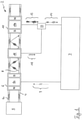
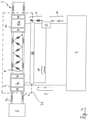
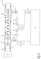
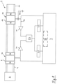
- FIG. 1 to 8 Various exemplary embodiments of a measuring arrangement 2 are shown, which carry out an ultrasonic flow measurement on a conductive object 4 designed as a pipeline.
- An interference source 5 interacting with the object 4 —schematically illustrated by direct contact of the interference source 5 with an end face of the object 4—generates interference that propagates through the object wall and couples into the induction coils 6a, 10a, 16 of the measuring system.
- a first ultrasonic wave 8 is generated in the object 4 by means of a first EMAT transmission transducer 6 of the measuring arrangement 2 positioned on or near a surface of the object 4 and having a first transmission transducer induction coil 6a having at least one conductor track.
- the first EMAT transmission converter 6 is excited by a control and evaluation unit 7 of the measuring arrangement 2 by an alternating current pulse 9 (ultrasonic waves, signals or pulses or current pulses in the Figures 3 , 5 , 7 and 8th not shown) which interacts with the magnetic field of the transducer - illustrated by the magnetic poles N, S.
- alternating current pulse 9 (ultrasonic waves, signals or pulses or current pulses in the Figures 3 , 5 , 7 and 8th not shown) which interacts with the magnetic field of the transducer - illustrated by the magnetic poles N, S.
- the polarity of the magnetic field shown in the figures is only used for illustrative purposes. It will be appreciated that the polarity can be different or that the magnetic field can be generated by a variable magnetic field electromagnet.
- a first received signal 12 is detected by means of a first EMAT receiving transducer 10 of the measuring arrangement 2 which is positioned on or near the surface of the object 4 and has a first receiving transducer induction coil 10a having at least one conductor track the first received signal 12 comprises a first ultrasonic signal 14 resulting at least in part from the first ultrasonic wave 8, which has propagated through at least part of the object 4, and a first electromagnetic interference signal.
- a second received signal 18, which includes at least one second electromagnetic interference signal is detected by means of a first receiving means of the measuring arrangement 2, in particular while the first received signal 12 is being detected by the first EMAT receiving transducer 6.
- At least the first received signal 12 and the second received signal 18 are processed together in an interference suppression operation by means of an interference suppression means 22 of the measuring arrangement 2, wherein at least the first received signal 12 is at least partially suppressed.
- the second received signal 18 is detected by a receiving means induction coil 16 of the first receiving means which is positioned on or near the surface of the object 4 and has at least one conductor track.
- the detected second interference signal is a coil interference signal.
- the receiving means induction coil 16 is preferably essentially identical in construction to the first receiving transducer induction coil 10a, as a result of which the first interference signal and the second interference signal have essentially the same characteristics, which leads to particularly effective interference suppression in the course of the interference suppression operation.
- no magnetic field is applied to the receiving means induction coil 16, so that the receiving means, in contrast to the EMAT transducers 6, 10, does not record any signal resulting from the first ultrasonic wave 8.
- the first transmission transducer induction coil 6a is used as the receiving means induction coil 16 to detect the second reception signal 18 .
- the measuring arrangement 2 has more than two EMAT transducers, a further induction coil of the measuring arrangement 2 that is different from the receiving transducer induction coil 10a can alternatively serve as the receiving means induction coil 16 .
- the first E-MAT transmit converter 6 is used as a receiving means.
- the first received signal 12 and the second received signal 18 pass through a first amplifier stage 24 before they are processed using the interference suppression means 22 in the interference suppression operation.
- the interference suppression device 22 with inductive components, such as a common-mode choke, the inductance in a sensor area 26 of the measuring arrangement 2, which comprises at least the first EMAT transmission converter 6 and the first EMAT reception converter 10, is not increased, as a result of which the Method can also be used in potentially explosive atmospheres.
- FIG. 12 shows a further embodiment in which the first EMAT transmission converter 6 is used as receiving means. For reasons of clarity, no ultrasonic waves, signals or pulses are shown here.
- the first received signal 12 and the second received signal 18 pass through an explosion protection barrier 28 (EX barrier) that shields the sensor area 26 of the measuring arrangement 2 Measurement arrangement 2 before they are processed in the interference suppression operation.
- EX barrier explosion protection barrier
- the method can also be carried out in potentially explosive areas.
- voltage-limiting diodes are used to implement the explosion protection barrier 28 .
- FIG 5 shows a further embodiment with an explosion protection barrier 28, in which the EMAT converters 6, 10 are designed both for sending and for receiving.
- the EMAT converter 6, 10 can be switched between a transmission and reception mode by means of switches 30.
- the explosion protection barrier 28 is to be placed in such a way that the sensor area 26 is shielded at least from the reception power leading to the interference suppression means 22 .
- the first received signal 12 and the second received signal 18 are processed together by means of electronic subtraction as an interference suppression operation.
- the signals are fed to a digital circuit as interference suppression means 22, and after amplification they first pass through an analog-to-digital converter 32 in each case.
- the first EMAT transmission converter 6 also serves as a second EMAT reception converter 36 and the first EMAT reception converter 10 also serves as a second EMAT transmission converter 34.
- the first EMAT transmission converter 6 generates the first ultrasonic wave 8 modulated with a first modulation pattern, while the first EMAT receiving transducer 10 records a first received signal 12, which includes both the first ultrasonic signal 14 resulting at least partially from the first ultrasonic wave 8 and the first interference signal.
- the second EMAT transmit transducer 34 also generates a second ultrasonic wave modulated with a second modulation pattern, with the second EMAT receive transducer 36 recording the second received signal 18, which, in addition to the second interference signal in the form of a coil interference signal, also consists at least partially of the second ultrasonic wave resulting second ultrasonic signal includes.
- the measuring arrangement 2 has a modulation means 38 which is part of the control and evaluation unit 7 in this embodiment.
- the first ultrasonic signal 14 can also be assigned to the first ultrasonic wave 8 and the second ultrasonic signal to the second ultrasonic wave after detection. Therefore, both the first received signal 12 and the second received signal can be processed together in the interference suppression operation running on the interference suppression means 22, with both received signals being at least partially suppressed.
- the interference-free overall signal is then fed to a first demodulation means 40 and a second demodulation means 42, with the first demodulation means 40 delivering the first ultrasonic signal 14 by demodulation in accordance with the first modulation pattern and the second demodulation means 42 delivering the second ultrasound signal by demodulation in accordance with the second modulation pattern. Finally, the suppressed first ultrasonic signal 14 and the suppressed second ultrasonic signal are forwarded separately to the control and evaluation unit 7 for further evaluation.
- the demodulation means 40, 42 can also be designed as individual components and/or integrated into the control and evaluation unit 7.
- the measuring arrangement 2 additionally has a second receiving means in the form of a grounded line 44, which is used to detect a third received signal.
- the third received signal includes a third electromagnetic interference signal, more precisely a grounding interference signal.
- This grounding interference signal has its origin in the fact that the object 4 is grounded and couples a potential difference to the measuring system which is galvanically isolated from it into the measuring system as an interference signal.
- the second receiving means is capacitively connected to a measuring line 46 of the measuring arrangement 2 in a signal-transmitting manner, as a result of which the galvanic isolation is maintained.
- the second EMAT receiving converter 36 serves as the first receiving means and records a coil interference signal as part of the second received signal 18 .
- the grounded line 18 serves as a second receiving means and records a ground noise signal as part of the third received signal.
- the first received signal 12, the second received signal 18 and the third received signal are processed together in the interference suppression operation, with the first received signal 12 and the second received signal 18 being at least partially suppressed. Become this way Both interference 5a, which originate from interference sources 5 interacting with the object 4, and interference resulting from the potential difference between the measuring system and grounded structures are suppressed. This significantly improves the signal-to-noise ratio in the flow measurement on which this is based.
- a correlation analysis is preferably carried out beforehand and/or during the ultrasonic measurement to determine a correlation, in particular an amplitude and/or phase relationship, between the first Received signal 12 and the third received signal or carried out between the first interference signal and the third interference signal. If a relation between the interference signals is determined by ascertaining corresponding correlation factors, characteristics of the first interference signal can be predicted or anticipated on the basis of an ongoing measurement of the second interference signal. This prediction can then be used in the course of the interference suppression operation in order to achieve improved interference suppression of the first received signal 12 and possibly the second received signal.
Landscapes
- Physics & Mathematics (AREA)
- General Physics & Mathematics (AREA)
- General Health & Medical Sciences (AREA)
- Immunology (AREA)
- Life Sciences & Earth Sciences (AREA)
- Chemical & Material Sciences (AREA)
- Analytical Chemistry (AREA)
- Biochemistry (AREA)
- Health & Medical Sciences (AREA)
- Pathology (AREA)
- Electromagnetism (AREA)
- Signal Processing (AREA)
- Engineering & Computer Science (AREA)
- Fluid Mechanics (AREA)
- Computer Networks & Wireless Communication (AREA)
- Investigating Or Analyzing Materials By The Use Of Ultrasonic Waves (AREA)
Applications Claiming Priority (1)
| Application Number | Priority Date | Filing Date | Title |
|---|---|---|---|
| DE102020123072.9A DE102020123072A1 (de) | 2020-09-03 | 2020-09-03 | Messverfahren und Messanordnung zur Entstörung eines Empfangssignals eines EMAT-Wandlers |
Publications (1)
| Publication Number | Publication Date |
|---|---|
| EP3964832A1 true EP3964832A1 (fr) | 2022-03-09 |
Family
ID=77564027
Family Applications (1)
| Application Number | Title | Priority Date | Filing Date |
|---|---|---|---|
| EP21194073.9A Pending EP3964832A1 (fr) | 2020-09-03 | 2021-08-31 | Procédé de mesure et agencement de mesure destinés à la suppression des interférences d'un signal de réception d'un transducteur emat |
Country Status (4)
| Country | Link |
|---|---|
| US (1) | US12209995B2 (fr) |
| EP (1) | EP3964832A1 (fr) |
| CA (1) | CA3129863A1 (fr) |
| DE (1) | DE102020123072A1 (fr) |
Cited By (1)
| Publication number | Priority date | Publication date | Assignee | Title |
|---|---|---|---|---|
| EP4248182A1 (fr) * | 2020-11-17 | 2023-09-27 | Commissariat à l'Energie Atomique et aux Energies Alternatives | Dispositif de contrôle non destructif d'une structure, comprenant un organe de réduction de bruits électromagnétique |
Families Citing this family (2)
| Publication number | Priority date | Publication date | Assignee | Title |
|---|---|---|---|---|
| CN116527463A (zh) * | 2023-06-26 | 2023-08-01 | 四川新川航空仪器有限责任公司 | 一种共模干扰信号抑制装置及方法 |
| CN119509635B (zh) * | 2024-10-22 | 2025-11-04 | 浙江威星智能仪表股份有限公司 | 一种超声波换能器接收自动屏蔽电路 |
Citations (4)
| Publication number | Priority date | Publication date | Assignee | Title |
|---|---|---|---|---|
| US4307616A (en) * | 1979-12-26 | 1981-12-29 | Rockwell International Corporation | Signal processing technique for ultrasonic inspection |
| US5581037A (en) * | 1992-11-06 | 1996-12-03 | Southwest Research Institute | Nondestructive evaluation of pipes and tubes using magnetostrictive sensors |
| DE102010006275A1 (de) * | 2010-01-26 | 2011-07-28 | Nordinkraft AG, 75177 | Verfahren und Vorrichtung zur Prüfung eines metallischen Prüfobjekts |
| DE102018122584A1 (de) * | 2018-03-21 | 2019-09-26 | Rosen Swiss Ag | Verfahren zur nichtinvasiven Bestimmung des Flusses oder der Durchflussrate in einem von einem gasförmigen Medium durchströmten, elektrisch leitenden Objekt sowie akustischer Durchflussmesser zur Durchführung des Verfahrens |
Family Cites Families (20)
| Publication number | Priority date | Publication date | Assignee | Title |
|---|---|---|---|---|
| US20140371931A1 (en) * | 2013-06-16 | 2014-12-18 | Mei-Jech Lin | W5RS: Anlinx & Milinx & Zilinx - the 23Less Green Technology for FSOC of Scalable iPindow of iPhome & Scalable Smart Window of Smart Home with Wire/Wireless/Solar/Battery Communication, Power Supplies & Conversions |
| US20050192727A1 (en) * | 1994-05-09 | 2005-09-01 | Automotive Technologies International Inc. | Sensor Assemblies |
| US7511443B2 (en) * | 2002-09-26 | 2009-03-31 | Barrett Technology, Inc. | Ultra-compact, high-performance motor controller and method of using same |
| US20070231872A1 (en) | 2004-07-27 | 2007-10-04 | Nativis, Inc. | System and Method for Collecting, Storing, Processing, Transmitting and Presenting Very Low Amplitude Signals |
| US7089099B2 (en) * | 2004-07-30 | 2006-08-08 | Automotive Technologies International, Inc. | Sensor assemblies |
| US8170809B2 (en) * | 2007-11-14 | 2012-05-01 | Fbs, Inc. | Guided waves for nondestructive testing of pipes |
| US7997139B2 (en) * | 2007-12-03 | 2011-08-16 | Fbs, Inc. | Guided wave pipeline inspection system and method with enhanced natural focusing techniques |
| EP2232123B1 (fr) * | 2008-01-11 | 2014-09-17 | PII Limited | Appareil et procédé d'inspection de pipelines utilisant deux modes d'oscillation ultrasoniques différents |
| US20090283569A1 (en) | 2008-05-13 | 2009-11-19 | General Electric Company | System and method for monitoring welding |
| US20160087687A1 (en) * | 2008-09-27 | 2016-03-24 | Witricity Corporation | Communication in a wireless power transmission system |
| US9515494B2 (en) * | 2008-09-27 | 2016-12-06 | Witricity Corporation | Wireless power system including impedance matching network |
| US8466583B2 (en) * | 2008-09-27 | 2013-06-18 | Witricity Corporation | Tunable wireless energy transfer for outdoor lighting applications |
| US20120313742A1 (en) * | 2008-09-27 | 2012-12-13 | Witricity Corporation | Compact resonators for wireless energy transfer in vehicle applications |
| US8410636B2 (en) * | 2008-09-27 | 2013-04-02 | Witricity Corporation | Low AC resistance conductor designs |
| US20120248888A1 (en) * | 2008-09-27 | 2012-10-04 | Kesler Morris P | Wireless energy transfer with resonator arrays for medical applications |
| US9396867B2 (en) * | 2008-09-27 | 2016-07-19 | Witricity Corporation | Integrated resonator-shield structures |
| US20160043571A1 (en) * | 2008-09-27 | 2016-02-11 | Witricity Corporation | Resonator enclosure |
| GB2578255B (en) * | 2017-06-14 | 2022-12-07 | Emulate Inc | Effects of space travel on human brain cells |
| US11131502B2 (en) * | 2017-08-14 | 2021-09-28 | Ut-Battelle, Llc | Heating system with induction power supply and electromagnetic acoustic transducer with induction power supply |
| US10833599B2 (en) * | 2017-11-06 | 2020-11-10 | Maxout Renewables, Inc. | Highly interleaved converter for reliable power processing |
-
2020
- 2020-09-03 DE DE102020123072.9A patent/DE102020123072A1/de active Pending
-
2021
- 2021-08-31 EP EP21194073.9A patent/EP3964832A1/fr active Pending
- 2021-09-03 CA CA3129863A patent/CA3129863A1/fr active Pending
- 2021-09-03 US US17/466,256 patent/US12209995B2/en active Active
Patent Citations (4)
| Publication number | Priority date | Publication date | Assignee | Title |
|---|---|---|---|---|
| US4307616A (en) * | 1979-12-26 | 1981-12-29 | Rockwell International Corporation | Signal processing technique for ultrasonic inspection |
| US5581037A (en) * | 1992-11-06 | 1996-12-03 | Southwest Research Institute | Nondestructive evaluation of pipes and tubes using magnetostrictive sensors |
| DE102010006275A1 (de) * | 2010-01-26 | 2011-07-28 | Nordinkraft AG, 75177 | Verfahren und Vorrichtung zur Prüfung eines metallischen Prüfobjekts |
| DE102018122584A1 (de) * | 2018-03-21 | 2019-09-26 | Rosen Swiss Ag | Verfahren zur nichtinvasiven Bestimmung des Flusses oder der Durchflussrate in einem von einem gasförmigen Medium durchströmten, elektrisch leitenden Objekt sowie akustischer Durchflussmesser zur Durchführung des Verfahrens |
Cited By (1)
| Publication number | Priority date | Publication date | Assignee | Title |
|---|---|---|---|---|
| EP4248182A1 (fr) * | 2020-11-17 | 2023-09-27 | Commissariat à l'Energie Atomique et aux Energies Alternatives | Dispositif de contrôle non destructif d'une structure, comprenant un organe de réduction de bruits électromagnétique |
Also Published As
| Publication number | Publication date |
|---|---|
| US20220065823A1 (en) | 2022-03-03 |
| CA3129863A1 (fr) | 2022-03-03 |
| US12209995B2 (en) | 2025-01-28 |
| DE102020123072A1 (de) | 2022-03-03 |
Similar Documents
| Publication | Publication Date | Title |
|---|---|---|
| EP0200183B1 (fr) | Procédé et dispositif pour le contrôle non-destructif de corps ferromagnétiques | |
| DE3834248C2 (fr) | ||
| DE102020123072A1 (de) | Messverfahren und Messanordnung zur Entstörung eines Empfangssignals eines EMAT-Wandlers | |
| DE102007039434A1 (de) | Verfahren und Vorrichtung zum Erfassen von Partikeln in einer strömenden Flüssigkeit | |
| DE102009022138A1 (de) | Vorrichtung und Verfahren für induktive Messungen | |
| DE69018439T2 (de) | Verfahren und Vorrichtung zum Prüfen des Antwortsignals eines Spannungswellensensors. | |
| DE60123043T2 (de) | Anzeige der leitfähigkeit in einem magnetischen durchflussmesser | |
| DE19950215C2 (de) | Verfahren zur Zustands-, Verschleiß- und Bruchüberwachung eines bewegten Maschinenteils sowie Vorrichtung zur Durchführung des Verfahrens | |
| EP2146204B1 (fr) | Procédé et dispositif destiné à l'évaluation de signaux de réception obtenus lors d'une éxamination ultrasonore et nondestructive d'un échantillon | |
| DE4322849C1 (de) | Verfahren zur Bestimmung der Laufzeit von Schallsignalen und Schallwellen-Laufzeit-Bestimmungsvorrichtung | |
| DE3530525C2 (de) | Vorrichtung zur zerstörungsfreien Werkstoffprüfung | |
| EP0677742B1 (fr) | Dispositif et procédé pour déterminer la distance de séparation d'une tête de mesure pendant le contrôle non-destructif de pièces métalliques par des transducteurs ultrasonores électromagnétiques | |
| EP3132282A1 (fr) | Dispositif et procédé de détection sonore d'un environnement | |
| EP1396720A2 (fr) | Appareil et procédé pour la detection de discontinuités dans un objet par l'emploi de transducteurs électromagnétiques acoustiques | |
| WO2019179645A1 (fr) | Procédé et ensemble de mesure destiné à la détection d'une perturbation électromagnétique sur l'âme dun conducteur électrique | |
| DE112014003706T5 (de) | Elektronisches Schlaginstrument sowie zugehöriger berührungsloser Sensor und zugehöriges Verfahren zur Signalerfassung | |
| DE19651922C2 (de) | Anpaßverstärker für eine Induktionssonde und Meßvorrichtung mit mindestens zweiim Abstand voneinander angeordneten Induktionssonden | |
| EP3887870B1 (fr) | Dispositif de mesure inductif et appareil et procédé d'étalonnage | |
| DE102022113015B4 (de) | Verfahren zur Signalübertragung zwischen einem Ultraschallwandler und einer Ultraschallelektronik sowie zugehörige Anordnung | |
| EP1093202B1 (fr) | Procédé pour détecter des conducteurs mises à la masse pour arrêter une perceuse | |
| DE10301734A1 (de) | Schaltungsanordnung zur galvanischen Trennung zweier Sensoren | |
| EP0532142B1 (fr) | Procédé et dispositif de contrÔle des pièces ferromagnétiques par ultrasons | |
| DE19804832B4 (de) | Vorrichtung zur akustischen Ortung von Fehlern in elektrischen Leitungen | |
| DE102008020325B4 (de) | Winkelsensor | |
| DE102004045990B4 (de) | Verfahren zum Prüfen eines geschirmten Kabels |
Legal Events
| Date | Code | Title | Description |
|---|---|---|---|
| PUAI | Public reference made under article 153(3) epc to a published international application that has entered the european phase |
Free format text: ORIGINAL CODE: 0009012 |
|
| STAA | Information on the status of an ep patent application or granted ep patent |
Free format text: STATUS: THE APPLICATION HAS BEEN PUBLISHED |
|
| AK | Designated contracting states |
Kind code of ref document: A1 Designated state(s): AL AT BE BG CH CY CZ DE DK EE ES FI FR GB GR HR HU IE IS IT LI LT LU LV MC MK MT NL NO PL PT RO RS SE SI SK SM TR |
|
| STAA | Information on the status of an ep patent application or granted ep patent |
Free format text: STATUS: REQUEST FOR EXAMINATION WAS MADE |
|
| 17P | Request for examination filed |
Effective date: 20220908 |
|
| RBV | Designated contracting states (corrected) |
Designated state(s): AL AT BE BG CH CY CZ DE DK EE ES FI FR GB GR HR HU IE IS IT LI LT LU LV MC MK MT NL NO PL PT RO RS SE SI SK SM TR |
|
| RAP1 | Party data changed (applicant data changed or rights of an application transferred) |
Owner name: ROSEN 2 HOLDING AG |
|
| STAA | Information on the status of an ep patent application or granted ep patent |
Free format text: STATUS: EXAMINATION IS IN PROGRESS |
|
| 17Q | First examination report despatched |
Effective date: 20240307 |
|
| RAP3 | Party data changed (applicant data changed or rights of an application transferred) |
Owner name: ROSENXT HOLDING AG |