EP3964853B1 - Système et procédé d'estimation et compensation de dérive d'oscillateur local dans des capteurs en cascade - Google Patents
Système et procédé d'estimation et compensation de dérive d'oscillateur local dans des capteurs en cascade Download PDFInfo
- Publication number
- EP3964853B1 EP3964853B1 EP21193057.3A EP21193057A EP3964853B1 EP 3964853 B1 EP3964853 B1 EP 3964853B1 EP 21193057 A EP21193057 A EP 21193057A EP 3964853 B1 EP3964853 B1 EP 3964853B1
- Authority
- EP
- European Patent Office
- Prior art keywords
- signal
- common
- baseband signals
- signals
- baseband
- Prior art date
- Legal status (The legal status is an assumption and is not a legal conclusion. Google has not performed a legal analysis and makes no representation as to the accuracy of the status listed.)
- Active
Links
Images




Classifications
-
- G—PHYSICS
- G01—MEASURING; TESTING
- G01S—RADIO DIRECTION-FINDING; RADIO NAVIGATION; DETERMINING DISTANCE OR VELOCITY BY USE OF RADIO WAVES; LOCATING OR PRESENCE-DETECTING BY USE OF THE REFLECTION OR RERADIATION OF RADIO WAVES; ANALOGOUS ARRANGEMENTS USING OTHER WAVES
- G01S7/00—Details of systems according to groups G01S13/00, G01S15/00, G01S17/00
- G01S7/02—Details of systems according to groups G01S13/00, G01S15/00, G01S17/00 of systems according to group G01S13/00
- G01S7/40—Means for monitoring or calibrating
-
- G—PHYSICS
- G01—MEASURING; TESTING
- G01S—RADIO DIRECTION-FINDING; RADIO NAVIGATION; DETERMINING DISTANCE OR VELOCITY BY USE OF RADIO WAVES; LOCATING OR PRESENCE-DETECTING BY USE OF THE REFLECTION OR RERADIATION OF RADIO WAVES; ANALOGOUS ARRANGEMENTS USING OTHER WAVES
- G01S13/00—Systems using the reflection or reradiation of radio waves, e.g. radar systems; Analogous systems using reflection or reradiation of waves whose nature or wavelength is irrelevant or unspecified
- G01S13/02—Systems using reflection of radio waves, e.g. primary radar systems; Analogous systems
- G01S13/0209—Systems with very large relative bandwidth, i.e. larger than 10 %, e.g. baseband, pulse, carrier-free, ultrawideband
-
- G—PHYSICS
- G01—MEASURING; TESTING
- G01S—RADIO DIRECTION-FINDING; RADIO NAVIGATION; DETERMINING DISTANCE OR VELOCITY BY USE OF RADIO WAVES; LOCATING OR PRESENCE-DETECTING BY USE OF THE REFLECTION OR RERADIATION OF RADIO WAVES; ANALOGOUS ARRANGEMENTS USING OTHER WAVES
- G01S13/00—Systems using the reflection or reradiation of radio waves, e.g. radar systems; Analogous systems using reflection or reradiation of waves whose nature or wavelength is irrelevant or unspecified
- G01S13/02—Systems using reflection of radio waves, e.g. primary radar systems; Analogous systems
- G01S13/06—Systems determining position data of a target
- G01S13/08—Systems for measuring distance only
- G01S13/32—Systems for measuring distance only using transmission of continuous waves, whether amplitude-, frequency-, or phase-modulated, or unmodulated
- G01S13/34—Systems for measuring distance only using transmission of continuous waves, whether amplitude-, frequency-, or phase-modulated, or unmodulated using transmission of continuous, frequency-modulated waves while heterodyning the received signal, or a signal derived therefrom, with a locally-generated signal related to the contemporaneously transmitted signal
-
- G—PHYSICS
- G01—MEASURING; TESTING
- G01S—RADIO DIRECTION-FINDING; RADIO NAVIGATION; DETERMINING DISTANCE OR VELOCITY BY USE OF RADIO WAVES; LOCATING OR PRESENCE-DETECTING BY USE OF THE REFLECTION OR RERADIATION OF RADIO WAVES; ANALOGOUS ARRANGEMENTS USING OTHER WAVES
- G01S7/00—Details of systems according to groups G01S13/00, G01S15/00, G01S17/00
- G01S7/02—Details of systems according to groups G01S13/00, G01S15/00, G01S17/00 of systems according to group G01S13/00
- G01S7/35—Details of non-pulse systems
- G01S7/352—Receivers
-
- G—PHYSICS
- G01—MEASURING; TESTING
- G01S—RADIO DIRECTION-FINDING; RADIO NAVIGATION; DETERMINING DISTANCE OR VELOCITY BY USE OF RADIO WAVES; LOCATING OR PRESENCE-DETECTING BY USE OF THE REFLECTION OR RERADIATION OF RADIO WAVES; ANALOGOUS ARRANGEMENTS USING OTHER WAVES
- G01S7/00—Details of systems according to groups G01S13/00, G01S15/00, G01S17/00
- G01S7/02—Details of systems according to groups G01S13/00, G01S15/00, G01S17/00 of systems according to group G01S13/00
- G01S7/40—Means for monitoring or calibrating
- G01S7/4004—Means for monitoring or calibrating of parts of a radar system
- G01S7/4017—Means for monitoring or calibrating of parts of a radar system of HF systems
-
- G—PHYSICS
- G01—MEASURING; TESTING
- G01S—RADIO DIRECTION-FINDING; RADIO NAVIGATION; DETERMINING DISTANCE OR VELOCITY BY USE OF RADIO WAVES; LOCATING OR PRESENCE-DETECTING BY USE OF THE REFLECTION OR RERADIATION OF RADIO WAVES; ANALOGOUS ARRANGEMENTS USING OTHER WAVES
- G01S13/00—Systems using the reflection or reradiation of radio waves, e.g. radar systems; Analogous systems using reflection or reradiation of waves whose nature or wavelength is irrelevant or unspecified
- G01S13/02—Systems using reflection of radio waves, e.g. primary radar systems; Analogous systems
- G01S13/06—Systems determining position data of a target
- G01S13/42—Simultaneous measurement of distance and other co-ordinates
- G01S13/44—Monopulse radar, i.e. simultaneous lobing
- G01S13/4418—Monopulse radar, i.e. simultaneous lobing with means for eliminating radar-dependent errors in angle measurements, e.g. multipath effects
-
- G—PHYSICS
- G01—MEASURING; TESTING
- G01S—RADIO DIRECTION-FINDING; RADIO NAVIGATION; DETERMINING DISTANCE OR VELOCITY BY USE OF RADIO WAVES; LOCATING OR PRESENCE-DETECTING BY USE OF THE REFLECTION OR RERADIATION OF RADIO WAVES; ANALOGOUS ARRANGEMENTS USING OTHER WAVES
- G01S13/00—Systems using the reflection or reradiation of radio waves, e.g. radar systems; Analogous systems using reflection or reradiation of waves whose nature or wavelength is irrelevant or unspecified
- G01S13/02—Systems using reflection of radio waves, e.g. primary radar systems; Analogous systems
- G01S13/06—Systems determining position data of a target
- G01S13/42—Simultaneous measurement of distance and other co-ordinates
- G01S13/44—Monopulse radar, i.e. simultaneous lobing
- G01S13/4454—Monopulse radar, i.e. simultaneous lobing phase comparisons monopulse, i.e. comparing the echo signals received by an interferometric antenna arrangement
-
- G—PHYSICS
- G01—MEASURING; TESTING
- G01S—RADIO DIRECTION-FINDING; RADIO NAVIGATION; DETERMINING DISTANCE OR VELOCITY BY USE OF RADIO WAVES; LOCATING OR PRESENCE-DETECTING BY USE OF THE REFLECTION OR RERADIATION OF RADIO WAVES; ANALOGOUS ARRANGEMENTS USING OTHER WAVES
- G01S13/00—Systems using the reflection or reradiation of radio waves, e.g. radar systems; Analogous systems using reflection or reradiation of waves whose nature or wavelength is irrelevant or unspecified
- G01S13/02—Systems using reflection of radio waves, e.g. primary radar systems; Analogous systems
- G01S13/50—Systems of measurement based on relative movement of target
- G01S13/58—Velocity or trajectory determination systems; Sense-of-movement determination systems
- G01S13/583—Velocity or trajectory determination systems; Sense-of-movement determination systems using transmission of continuous unmodulated waves, amplitude-, frequency-, or phase-modulated waves and based upon the Doppler effect resulting from movement of targets
- G01S13/584—Velocity or trajectory determination systems; Sense-of-movement determination systems using transmission of continuous unmodulated waves, amplitude-, frequency-, or phase-modulated waves and based upon the Doppler effect resulting from movement of targets adapted for simultaneous range and velocity measurements
-
- G—PHYSICS
- G01—MEASURING; TESTING
- G01S—RADIO DIRECTION-FINDING; RADIO NAVIGATION; DETERMINING DISTANCE OR VELOCITY BY USE OF RADIO WAVES; LOCATING OR PRESENCE-DETECTING BY USE OF THE REFLECTION OR RERADIATION OF RADIO WAVES; ANALOGOUS ARRANGEMENTS USING OTHER WAVES
- G01S13/00—Systems using the reflection or reradiation of radio waves, e.g. radar systems; Analogous systems using reflection or reradiation of waves whose nature or wavelength is irrelevant or unspecified
- G01S13/88—Radar or analogous systems specially adapted for specific applications
- G01S13/93—Radar or analogous systems specially adapted for specific applications for anti-collision purposes
- G01S13/931—Radar or analogous systems specially adapted for specific applications for anti-collision purposes of land vehicles
-
- G—PHYSICS
- G01—MEASURING; TESTING
- G01S—RADIO DIRECTION-FINDING; RADIO NAVIGATION; DETERMINING DISTANCE OR VELOCITY BY USE OF RADIO WAVES; LOCATING OR PRESENCE-DETECTING BY USE OF THE REFLECTION OR RERADIATION OF RADIO WAVES; ANALOGOUS ARRANGEMENTS USING OTHER WAVES
- G01S13/00—Systems using the reflection or reradiation of radio waves, e.g. radar systems; Analogous systems using reflection or reradiation of waves whose nature or wavelength is irrelevant or unspecified
- G01S13/88—Radar or analogous systems specially adapted for specific applications
- G01S13/93—Radar or analogous systems specially adapted for specific applications for anti-collision purposes
- G01S13/931—Radar or analogous systems specially adapted for specific applications for anti-collision purposes of land vehicles
- G01S2013/9327—Sensor installation details
- G01S2013/93271—Sensor installation details in the front of the vehicles
-
- G—PHYSICS
- G01—MEASURING; TESTING
- G01S—RADIO DIRECTION-FINDING; RADIO NAVIGATION; DETERMINING DISTANCE OR VELOCITY BY USE OF RADIO WAVES; LOCATING OR PRESENCE-DETECTING BY USE OF THE REFLECTION OR RERADIATION OF RADIO WAVES; ANALOGOUS ARRANGEMENTS USING OTHER WAVES
- G01S13/00—Systems using the reflection or reradiation of radio waves, e.g. radar systems; Analogous systems using reflection or reradiation of waves whose nature or wavelength is irrelevant or unspecified
- G01S13/88—Radar or analogous systems specially adapted for specific applications
- G01S13/93—Radar or analogous systems specially adapted for specific applications for anti-collision purposes
- G01S13/931—Radar or analogous systems specially adapted for specific applications for anti-collision purposes of land vehicles
- G01S2013/9327—Sensor installation details
- G01S2013/93272—Sensor installation details in the back of the vehicles
-
- G—PHYSICS
- G01—MEASURING; TESTING
- G01S—RADIO DIRECTION-FINDING; RADIO NAVIGATION; DETERMINING DISTANCE OR VELOCITY BY USE OF RADIO WAVES; LOCATING OR PRESENCE-DETECTING BY USE OF THE REFLECTION OR RERADIATION OF RADIO WAVES; ANALOGOUS ARRANGEMENTS USING OTHER WAVES
- G01S7/00—Details of systems according to groups G01S13/00, G01S15/00, G01S17/00
- G01S7/02—Details of systems according to groups G01S13/00, G01S15/00, G01S17/00 of systems according to group G01S13/00
-
- G—PHYSICS
- G01—MEASURING; TESTING
- G01S—RADIO DIRECTION-FINDING; RADIO NAVIGATION; DETERMINING DISTANCE OR VELOCITY BY USE OF RADIO WAVES; LOCATING OR PRESENCE-DETECTING BY USE OF THE REFLECTION OR RERADIATION OF RADIO WAVES; ANALOGOUS ARRANGEMENTS USING OTHER WAVES
- G01S7/00—Details of systems according to groups G01S13/00, G01S15/00, G01S17/00
- G01S7/02—Details of systems according to groups G01S13/00, G01S15/00, G01S17/00 of systems according to group G01S13/00
- G01S7/027—Constructional details of housings, e.g. form, type, material or ruggedness
- G01S7/028—Miniaturisation, e.g. surface mounted device [SMD] packaging or housings
-
- G—PHYSICS
- G01—MEASURING; TESTING
- G01S—RADIO DIRECTION-FINDING; RADIO NAVIGATION; DETERMINING DISTANCE OR VELOCITY BY USE OF RADIO WAVES; LOCATING OR PRESENCE-DETECTING BY USE OF THE REFLECTION OR RERADIATION OF RADIO WAVES; ANALOGOUS ARRANGEMENTS USING OTHER WAVES
- G01S7/00—Details of systems according to groups G01S13/00, G01S15/00, G01S17/00
- G01S7/02—Details of systems according to groups G01S13/00, G01S15/00, G01S17/00 of systems according to group G01S13/00
- G01S7/03—Details of HF subsystems specially adapted therefor, e.g. common to transmitter and receiver
- G01S7/032—Constructional details for solid-state radar subsystems
-
- G—PHYSICS
- G01—MEASURING; TESTING
- G01S—RADIO DIRECTION-FINDING; RADIO NAVIGATION; DETERMINING DISTANCE OR VELOCITY BY USE OF RADIO WAVES; LOCATING OR PRESENCE-DETECTING BY USE OF THE REFLECTION OR RERADIATION OF RADIO WAVES; ANALOGOUS ARRANGEMENTS USING OTHER WAVES
- G01S7/00—Details of systems according to groups G01S13/00, G01S15/00, G01S17/00
- G01S7/02—Details of systems according to groups G01S13/00, G01S15/00, G01S17/00 of systems according to group G01S13/00
- G01S7/35—Details of non-pulse systems
- G01S7/352—Receivers
- G01S7/356—Receivers involving particularities of FFT processing
-
- G—PHYSICS
- G01—MEASURING; TESTING
- G01S—RADIO DIRECTION-FINDING; RADIO NAVIGATION; DETERMINING DISTANCE OR VELOCITY BY USE OF RADIO WAVES; LOCATING OR PRESENCE-DETECTING BY USE OF THE REFLECTION OR RERADIATION OF RADIO WAVES; ANALOGOUS ARRANGEMENTS USING OTHER WAVES
- G01S7/00—Details of systems according to groups G01S13/00, G01S15/00, G01S17/00
- G01S7/02—Details of systems according to groups G01S13/00, G01S15/00, G01S17/00 of systems according to group G01S13/00
- G01S7/40—Means for monitoring or calibrating
- G01S7/4004—Means for monitoring or calibrating of parts of a radar system
- G01S7/4021—Means for monitoring or calibrating of parts of a radar system of receivers
-
- G—PHYSICS
- G01—MEASURING; TESTING
- G01S—RADIO DIRECTION-FINDING; RADIO NAVIGATION; DETERMINING DISTANCE OR VELOCITY BY USE OF RADIO WAVES; LOCATING OR PRESENCE-DETECTING BY USE OF THE REFLECTION OR RERADIATION OF RADIO WAVES; ANALOGOUS ARRANGEMENTS USING OTHER WAVES
- G01S7/00—Details of systems according to groups G01S13/00, G01S15/00, G01S17/00
- G01S7/02—Details of systems according to groups G01S13/00, G01S15/00, G01S17/00 of systems according to group G01S13/00
- G01S7/41—Details of systems according to groups G01S13/00, G01S15/00, G01S17/00 of systems according to group G01S13/00 using analysis of echo signal for target characterisation; Target signature; Target cross-section
-
- H—ELECTRICITY
- H01—ELECTRIC ELEMENTS
- H01Q—ANTENNAS, i.e. RADIO AERIALS
- H01Q1/00—Details of, or arrangements associated with, antennas
- H01Q1/27—Adaptation for use in or on movable bodies
- H01Q1/32—Adaptation for use in or on road or rail vehicles
- H01Q1/3208—Adaptation for use in or on road or rail vehicles characterised by the application wherein the antenna is used
- H01Q1/3233—Adaptation for use in or on road or rail vehicles characterised by the application wherein the antenna is used particular used as part of a sensor or in a security system, e.g. for automotive radar, navigation systems
-
- H—ELECTRICITY
- H01—ELECTRIC ELEMENTS
- H01Q—ANTENNAS, i.e. RADIO AERIALS
- H01Q21/00—Antenna arrays or systems
- H01Q21/28—Combinations of substantially independent non-interacting antenna units or systems
Definitions
- This disclosure generally relates to automotive radar systems, and more particularly relates to local oscillator (LO) drift estimation and compensation in cascaded sensors in an automotive radar system.
- LO local oscillator
- Radar systems are becoming increasingly common in the automotive industry, being used, for example, as sensors for assisted parking, automatic cruise control speed adjustment (adaptive cruise control), headway alert, collision warning and mitigation, and brake support. Radar systems perform detection and ranging by transmitting an electromagnetic wave, such as a pulse, from a transmission antenna and measuring the time taken for the reflected signal to be detected at a receiving sensor. The amount of time taken for a reflected signal to reach an obstacle and be reflected back provides an indication of the range of that obstacle from the radar system.
- an electromagnetic wave such as a pulse
- This document discloses a method for calibrating two receiving units of a radar sensor, which has an array of receiving antennas formed by two part-arrays and an evaluation device, which is designed to perform an angle estimation for localised radar targets by means of phase differences between the signals received by the receiving antennas, each receiving unit having parallel reception paths for the signals of the receiving antennas of one of the part-arrays, characterised by the following steps: analysing the received signals and deciding whether a multi-target or a single-target scenario is present, in the event of a single-target scenario measuring phases of the signals received in the part-array, and calculating a phase offset between the two part-arrays, and calibrating the phases in the two receiving units by means of the calculated phase offset.
- the processor may be further configured to determine a delay time between the first common baseband signal and the second common baseband signal.
- the IC device devices may be further configured to digitize the baseband signals, where outputting the baseband signals may comprise outputting the digitized signals.
- the processor may be further configured to perform a Fast Fourier Transform (FFT) on the digitized baseband signals to obtain transformed signals including common transformed signal associated with the common sensor inputs.
- FFT Fast Fourier Transform
- the processor may be further configured to determine a complex phase shift between common first transformed signal and the common second transformed signal in a frequency domain.
- the processor may be further configured to shift a phase of at least one of the sets of transformed baseband signals based upon the complex phase shift.
- the first IC device may be further configured to generate the first LO signal
- the second IC device may be further configured to receive the second LO signal from the first ICdevice.
- the antennas of the antenna array may be arranged in a line and each antenna is spaced apart from a next antenna at a distance of lambda/2 or more, where lambda is a wavelength of a carrier wave of a FMCW chirp of the FMCW radar system.
- FIG. 1 illustrates a radar system 110 configured to provide for detection and ranging of an object 120 in a space 100 around the radar system.
- Radar system 110 is a MIMO radar system, including multiple transmit antennas and multiple receive antennas. Radar system 110 is configured to emit a series of encoded detection signals on each transmit antenna, to receive the reflected signals from object 120, and to determine the range to the object and the incident angle to the object.
- the angular resolution of radar system 110 is directly related to the total antenna aperture, which is determined by the number of receive antennas and their localization with respect to each other.
- the receive antennas of radar system 110 are typically located at a distance of lambda/2 ( ⁇ /2) apart, or less, where ⁇ is the wavelength of the carrier signal of the detection signal, that is, the wavelength associated with the middle frequency of the detection signals.
- Typical MIMO radar systems may have apertures in the range of 6 to 10 lambda, which,in combination with the lambda/w criteria for antenna placement, leads to antenna arrays of 12 to 20 receive antennas. It will be understood that in practice, a distance of more than lambda/2 ( ⁇ /2) may be utilized as needed or desired.
- radar system 110 is implemented using one or more radio frequency (RF) integrated circuits (IC) or monolithic microwave integrated circuits (MMICs).
- RF radio frequency
- IC integrated circuits
- MMICs monolithic microwave integrated circuits
- a particular IC or MMIC may provide a transmit (TX) capability with a number of transmit channels, provides a receive (RX) capability with a number of receive channels, or may provide a transmit and receive (TX/RX) capability.
- TX transmit
- RX receive
- TX/RX transmit and receive
- FIG. 2 illustrates various embodiments of cascaded radar systems 200 and 250, similar to radar system 100.
- Radar systems 200 and 140 are designed utilizing a transmit IC 202, and one or more receive ICs 204.
- transmit IC 202 may be configured to include two transmit channels and to provide an output for a local oscillator (LO) signal
- receive IC 204 may be configured to include four receive channels and to provide an input for the LO signal from the transmit IC.
- Radar system 200 has an antenna array 206 with six antennas.
- Antenna array 206 includes two transmit antennas to emit detection signals from the two transmit channels of transmit IC 202, and includes four receive antennas to receive reflected signals from the four receive channels of receive IC 204.
- Receive IC 204 receives the LO signal from transmit IC 202.
- Radar system 250 has an antenna array 256 with 13 antennas.
- Antenna array 146 includes a single transmit antenna to emit a detection signal from one of the transmit channels of transmit IC 202, and includes 12 receive antennas.
- four receive antennas are connected to a first receive IC 204A
- four receive antennas are connected to a second receive IC 204B
- four receive antennas are connected to a third receive IC 204C.
- Receive ICs 204A, 204B, and 204C each receive the LO signal from transmit IC 202.
- transmit IC 202 will include other connections and interfaces (not illustrated), such as a crystal or clock input, one or more synchronization signal to synchronize the operation of the transmit IC with the one or more receive ICs 204, and other inputs or outputs, as needed or desired.
- connections and interfaces such as a crystal or clock input, one or more synchronization signal to synchronize the operation of the transmit IC with the one or more receive ICs 204, and other inputs or outputs, as needed or desired.
- receive IC 204 will include other connections and interfaces (not illustrated), such as one or more RF signal output, one or more IF signal output, for example where the receive IC includes down-converters to mix the received signals from the receive channels to the IF frequency, one or more data output, for example where the receive IC includes ADCs to digitize the IF signals, one or more synchronization signal to synchronize the operation of the receive IC with transmit IC 202 and with other receive ICs if present, and other inputs or outputs,as needed or desired.
- connections and interfaces such as one or more RF signal output, one or more IF signal output, for example where the receive IC includes down-converters to mix the received signals from the receive channels to the IF frequency, one or more data output, for example where the receive IC includes ADCs to digitize the IF signals, one or more synchronization signal to synchronize the operation of the receive IC with transmit IC 202 and with other receive ICs if present, and other inputs or output
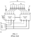
- FIG. 3 illustrates a radar system 300 similar to radar system 100.
- Radar system 300 includes a first transmit/receive IC 310, a second transmit/receive IC 320, and a signal processing IC 340.
- Transmit/receive ICs 310 and 320 represent RF ICs or MMICs which may more may not be identically specified, as needed or desired.
- Transmit/receive ICs 310 and 320 each include at least one transmit channel, and at least four receive channels.
- the transmit channel of IC 310 is connected to a transmission antenna 312, and the four receive channels of IC 310 are connected to an antenna array 314 of four receive antennas.
- the four receive antennas of antenna array 314 are designated, from left to right, as RX(M.1), RX(M.2), RX(M.3), and RX(M.4), and each antenna located at a lambda/2 spacing from the next antenna,as described above.
- the transmit channel of IC 320 is connected to a transmission antenna 322, and the four receive channels of IC 320 are connected to an antenna array 324 of four receive antennas.
- the four receive antennas of antenna array 324 are designated, from left to right, as RX(S.1), RX(S.2), RX(S.3), and RX(S.4), and each antenna is located at a lambda/2 spacing from the next antenna.
- antenna RX(M.4) is located at the lambda/2 spacing from antenna RX(S.1), such that the antennas of antenna arrays 314 and 324 are together configured as a single receive antenna array 330 of eight antennas.
- IC 310 further includes a clock or crystal input to which, in the illustrated example, a crystal is connected.
- the crystal is utilized by IC 310 as an input to derive a LO signal.
- the LO signal derived from the crystal is utilized internally in IC 310 to generate a detection signal to be emitted on transmit antenna 312, and in the down-converting of the detected signals from receive antenna array 314 to the baseband frequency.
- the LO signal is also provided to a LO output (LO_OUT) of IC 310.
- IC 310 may be referred to as a "master" IC.
- IC 320 includes a LO input (LO_IN) to receive the LO signal from IC 310.
- IC 320 may be referred to as a "slave" IC.
- the LO signal from LO_IN is utilized internally in IC 320 to generate a detection signal to be emitted on transmit antenna 322, and in the down-converting of the detected signals from receive antenna array 324 to the baseband frequency.
- IC 310 includes a chirp_start output that is provided to a chirp_start input of IC 320 to synchronize the start of the detection signals by IC 310 with the start of the detection signals by IC 320.
- the details of generating FMCW detection signals and the down-converting of detected signals are known in the art, and will not be further described herein except as needed to illustrate the current embodiments.
- the crystal is further utilized by IC 310 to derive a 40 MHz clock for the operation of ADCs in the IC that digitize the down-converted detected signals from antenna array 314.
- IC 310 includes a 40 MHz output that is connected to a 40 MHz input of IC 320 for the operation ofADCs in IC 320 that digitize the down-converted detected signals from antenna array 324, and to synchronize the digitization operations of the ADCs in ICs 310 and 320.
- ICs 310 and 320 each include a high-speed digital communication interface for the communication of the digitized detected signals from respective antenna arrays 314 and 324 to processing IC 340 for processing.
- An example of a high-speed digital communication interface may include a Mobile Industry Processor Interface (MIPI) Camera Serial Interface-2 (CSI-2) interface, a Low Voltage Differential Signaling (LVDS) interface, or the like, as needed of desired.
- MIPI Mobile Industry Processor Interface
- CSI-2 Camera Serial Interface-2
- LVDS Low Voltage Differential Signaling
- the details of digitizing detected signals and communicating digitized signals via digital communication interfaces are known in the art, and will not be further described herein except as needed to illustrate the current embodiments.
- ICs 310 and 320 each include a low-speed digital communication interface that is connected to processing IC 340, whereby processing IC 340 communicates with ICs 310 and 320 to set up the operating parameters of ICs 310 and 320, to monitor the operations of ICs 310 and 320, and to modify the operating parameters of ICs 310 and 320, as needed or desired.
- An example of a low-speed digital communication interface may include a Serial Peripheral Interface (SPI), or the like, as needed or desired.
- SPI Serial Peripheral Interface
- Processing IC 340 represents a digital signal processing device configured to extract object detection, range, speed, and incident angle information from the digitized detected signals from ICs 310 and 320.
- An example of processing IC 130 may include a microcontroller unit (MCU), a digital signal processor (DSP), a field-programmable gate array (FPGA) device, or the like.
- MCU microcontroller unit
- DSP digital signal processor
- FPGA field-programmable gate array
- the signals between the ICs or MMICs need to be highly phase coherent.
- the signals utilized to down-convert the detection signals should be in phase, not only within each IC or MMIC, but also between the various ICs or MMICs, in order to reduce angular errors in the determination of the angle of incidence of the detected objects.
- the signals utilized to down-convert the detection signals should be in phase, not only within each of ICs 310 and 320, but also between the ICs.
- ICs 310 and 320 represent identically specified ICs, such as were each IC is of a same type and part number, or where the ICs are of different types, but are from a common family of components.
- ICs 310 and 320 may be specified, such as by a design rule or a design recommendation.
- ICs 310 and 320 may be configured such that, if the specified placement and interconnections are followed, the ICs are designed to ensure that the LO signals as used internally to the ICs are synchronized with each other, such as by providing an internal delay of a known duration to the internal LO in one or the other of the ICs.
- the phase coherence of the detected signals from IC 310 will be understood to be high, that is, within a specified tolerance, the coherence of the detected signals from IC 320 will be understood to be high, and the coherence between the detected signals from IC 310 and the detected signals form IC 320 will be understood to also be high.
- the configuration illustrated by radar system 300 provides a simple and compact design.
- phase coherence of the LO signal may not be adequate.
- thermal variations between IC 310 and IC 320, and between the ICs and a printed circuit board (PCB) or other circuit board upon which the ICs are mounted may lead to uncompensated decoherence of the LO signal as used each IC.
- radar system 300 may be representative of radar systems with more than one slave IC, and where the LO_OUT output from IC 310 is provided to the LO_IN inputs of two or more slave ICs.
- additional slave ICs may be understood to be placed to the right of IC 320.
- the signal traces between the LO-OUT output of IC 130, and a LO_IN input of the additional slave IC will be understood to be longer than the signal trace between IC 310 and IC 320.
- each additional slave IC will be seen to have a longer trace length, and hence the LO signal to each additional IC will be understood to be more out of phase with the LO signal as used by IC 310.
- FIG. 4 illustrates a radar system 400 similar to radar systems 100 and 300.
- Radar system 400 includes a first transmit/receive IC 410, a second transmit/receive IC 420, and a signal processing IC 440.
- Transmit/receive ICs 410 and 420 represent RF ICs or MMICs which may more may not be identically specified, as needed or desired.
- Transmit/receive ICs 410 and 420 each include at least one transmit channel, and at least four receive channels.
- the transmit channel of IC 410 is connected to a transmission antenna 412, and the four receive channels of IC 410 are connected to an antenna array 414 of four receive antennas.
- the four receive antennas of antenna array 414 are designated, from left to right, as RX(M.1), RX(M.2), RX(M.3), and RX(M.4), and each antenna located at a lambda/2 spacing from the next antenna, as described above.
- the transmit channel of IC 420 is connected to a transmission antenna 422, and the four receive channels of IC 420 are connected to an antenna array 424 of four receive antennas.
- the four receive antennas of antenna array 424 are designated, from left to right, as RX(S.1), RX(S.2), RX(S.3), and RX(S.4), and each antenna is located at a lambda/2 spacing from the next antenna.
- antenna RX(M.4) is located at the lambda/2 spacing from antenna RX(S.1), such that the antennas of antenna arrays 414 and 424 are together configured as a single receive antenna array 430 of eight antennas.
- IC 410 further includes a clock or crystal input to which, in the illustrated example, a crystal is connected. The crystal is utilized by IC 410 as an input to derive a LO signal.
- the LO signal derived from the crystal provided to a LO output (LO_OUT) of IC 410.
- IC410 is the master IC.
- IC 410 further includes a LO input (LO_IN) to receive the LO signal.
- IC 410 does not use the internal LO signal, but instead utilizes the LO signal from the LO input to generate a detection signal to be emitted on transmit antenna 412, and in the down-converting of the detected signals from receive antenna array 414 to the baseband frequency.
- ICs 410 and 420 each include a high-speed digital communication interface for the communication of the digitized detected signals from respective antenna arrays 414 and 424 to processing IC 440 for processing.
- ICs 410 and 420 each include a low-speed digital communication interface that is connected to processing IC 440, whereby processing IC 440 communicates with ICs 410 and 420 to set up the operating parameters of ICs 410 and 420, to monitor the operations of ICs 410 and 420, and to modify the operating parameters of ICs 410 and 420, as needed or desired.
- Processing IC 440 represents a digital signal processing device configured to extract object detection, range, speed, and incident angle information from the digitized detected signals from ICs 410 and 420.
- ICs 510 and 520 represent identically specified ICs, such as were each IC is of a same type and part number, or where the ICs are of different types, but are from a common family of components. As such, and similarly to radar system 300, the placement of, and interconnections between ICs 510 and 520 may be specified, such as by a design rule or a design recommendation.
- the phase offsets for each object i.e., each frequency peak
- IC 540 utilizes the phase offset between receive channels RX(M.4) and RX(S.1) to correct the sets of values as needed.
- the first and second digitized IF signals are received in block 610.
- a digital signal processing IC can receive the digitized IF signals from the first and second receiver ICs.
- a phase difference between the first and second digitized IF signals is determined in block 612.
- the digital signal processing IC can determine the phase difference in the time-domain or in the frequency-domain, as needed or desired.
Landscapes
- Engineering & Computer Science (AREA)
- Radar, Positioning & Navigation (AREA)
- Remote Sensing (AREA)
- Physics & Mathematics (AREA)
- Computer Networks & Wireless Communication (AREA)
- General Physics & Mathematics (AREA)
- Electromagnetism (AREA)
- Radar Systems Or Details Thereof (AREA)
Claims (13)
- Système radar à ondes continues modulées en fréquence, FMCW, comprenant :un réseau d'antennes (530) comprenant C antennes, où C = A + B - 1, et où A, B, et C sont des nombres entiers supérieurs à un ;un premier dispositif à circuit intégré (IC) (510) comprenant A premières entrées de capteur, chaque première entrée de capteur étant couplée à A premières (514, 516) des antennes, le premier dispositif IC étant configuré pour recevoir sur chaque première entrée de capteur un premier signal réfléchi associé, pour mélanger les premiers signaux réfléchis à des premiers signaux en bande de base associés sur la base d'un premier signal d'oscillateur local, LO, et pour émettre les premiers signaux en bande de base, le premier signal LO ayant un premier déphasage ;un second dispositif IC (520) comprenant B secondes entrées de capteur, chaque seconde entrée de capteur étant couplée à B dernières (524, 516) des antennes de sorte qu'une entrée commune des premières entrées de capteur et une entrée commune des secondes entrées de capteur sont toutes deux couplées à une antenne commune (516), le second dispositif IC étant configuré pour recevoir sur chaque seconde entrée de capteur un second signal réfléchi associé, mélanger les seconds signaux réfléchis aux seconds signaux en bande de base associés sur la base d'un second signal d'oscillateur local, LO, et émettre les seconds signaux en bande de base, le second signal LO ayant un second déphasage, les premier et second signaux LO étant basés sur un signal LO commun, et un premier signal en bande de base commun étant associé à la première entrée de capteur commune et un second signal en bande de base commun étant associé à la seconde entrée de capteur commune ; etun processeur (540) configuré pour recevoir les premiers signaux en bande de base et les seconds signaux en bande de base, pour déterminer une différence entre le premier déphasage et le second déphasage sur la base du premier signal en bande de base commun et du second signal en bande de base commun, et pour corriger au moins l'un des premiers signaux en bande de base et des seconds signaux en bande de base sur la base de la différence entre le premier déphasage et le second déphasage.
- Système radar FMCW selon la revendication 1, lors de la détermination de la différence entre le premier déphasage et le second déphasage, le processeur étant en outre configuré pour déterminer un temps de retard entre le premier signal en bande de base commun et le second signal en bande de base commun.
- Système radar FMCW selon la revendication 1 ou 2, lors de la correction de l'au moins un des premiers signaux en bande de base et des seconds signaux en bande de base, le processeur étant en outre configuré pour retarder l'au moins un des premiers signaux en bande de base et des seconds signaux en bande de base par le temps de retard.
- Système radar FMCW selon l'une quelconque des revendications précédentes :le premier dispositif IC étant en outre configuré pour numériser les premiers signaux en bande de base, l'émission en sortie des premiers signaux en bande de base comprenant l'émission en sortie de premiers signaux numérisés incluant un premier signal numérisé commun associé à la première entrée de capteur commune ; etle second dispositif IC étant en outre configuré pour numériser les seconds signaux en bande de base, l'émission en sortie des seconds signaux en bande de base comprenant l'émission en sortie des seconds signaux numérisés, comprenant un second signal numérisé commun associé à la seconde entrée de capteur commune.
- Système radar FMCW selon la revendication 4, le processeur étant en outre configuré pour effectuer une transformée de Fourier rapide, FFT, sur les premiers signaux en bande de base numérisés afin d'obtenir des premiers signaux transformés comprenant un premier signal transformé commun associé au premier signal numérisé commun, et pour effectuer la FFT sur les seconds signaux en bande de base numérisés afin d'obtenir des seconds signaux transformés comprenant un second signal transformé commun associé au second signal numérisé commun.
- Système radar FMCW selon la revendication 5, lors de la détermination de la différence entre le premier déphasage et le second déphasage, le processeur étant en outre configuré pour déterminer un déphasage complexe entre le premier signal transformé commun et le second signal transformé commun dans un domaine de fréquence.
- Système radar FMCW selon la revendication 6, lors de la correction de l'au moins un des premiers signaux en bande de base et des seconds signaux en bande de base, le processeur étant en outre configuré pour décaler une phase d'au moins un des premiers signaux en bande de base transformés et des seconds signaux en bande de base transformés sur la base du déphasage complexe.
- Système radar FMCW selon l'une quelconque des revendications précédentes :le premier dispositif IC étant en outre configuré pour générer le premier signal LO ; etle second dispositif IC étant en outre configuré pour recevoir le second signal LO du premier dispositif IC.
- Système radar selon n'importe quelle revendication précédente, les antennes du réseau d'antennes étant agencées en ligne et chaque antenne étant espacée d'une antenne suivante à une distance de lambda/2 ou moins, où lambda est une longueur d'onde d'une onde porteuse d'un chirp FMCW du système radar FMCW.
- Procédé de compensation des déphasages d'oscillateur local, LO, dans des dispositifs à circuit intégré, IC, en cascade d'un système radar à ondes continues modulées en fréquence, FMCW, le procédé comprenant :la fourniture d'un réseau d'antennes (530) du système radar FMCW, le réseau d'antennes comprenant C antennes, où C = A + B - 1, et où A, B, et C sont des nombres entiers supérieurs à un ;le couplage de A premières entrées de capteur d'un premier dispositif IC (510) à A premières (514, 516) des antennes ; la réception, sur chaque première entrée de capteur d'un premier signal réfléchi associé ;le mélange, dans le premier dispositif IC, des premiers signaux réfléchis à des premiers signaux en bande de base associés sur la base d'un premier signal d'oscillateur local, LO, le premier signal LO ayant un premier déphasage, et un premier signal en bande de base commun étant associé à la première entrée de capteur commune ;l'émission en sortie, à partir du premier dispositif IC, des premiers signaux en bande de base ;le couplage de B secondes entrées de capteur d'un second dispositif IC (520) à B dernières (524, 516) des antennes de sorte qu'une entrée commune des premières entrées de capteur et une entrée commune des secondes entrées de capteur soient toutes deux couplées à une antenne commune ;la réception, sur chaque seconde entrée de capteur, d'un second signal réfléchi associé ;le mélange, dans le second dispositif IC, des seconds signaux réfléchis à des seconds signaux en bande de base associés, sur la base d'un second signal d'oscillateur local, LO, le second signal LO ayant un second déphasage, les premier et second signaux LO étant basés sur un signal LO commun, et un second signal en bande de base commun étant associé à la seconde entrée de capteur commune ;l'émission en sortie, à partir du second dispositif IC, des seconds signaux en bande de base ; le procédé comprenant en outre :la réception, par un processeur (540) du système radar FMCW, des premiers signaux en bande de base et des seconds signaux en bande de base ;la détermination, par le processeur, d'une différence entre le premier déphasage et le second déphasage sur la base du premier signal en bande de base commun et du second signal en bande de base commun ; etla correction, par le processeur, d'au moins l'un des premiers signaux en bande de base et des seconds signaux en bande de base sur la base de la différence entre le premier déphasage et le second déphasage.
- Procédé selon la revendication 10, lors de la détermination de la différence entre le premier déphasage et le second déphasage, le procédé comprenant en outre :
la détermination, par le processeur, d'un temps de retard entre le premier signal en bande de base commun et le second signal en bande de base commun. - Procédé selon la revendication 11, lors de la correction de l'au moins un des premiers signaux en bande de base et des seconds signaux en bande de base, le procédé comprenant en outre : le retardement, par le processeur, de l'au moins un des premiers signaux en bande de base et des seconds signaux en bande de base par le temps de retard.
- Procédé selon l'une quelconque des revendications 11 et 12 comprenant en outre :la numérisation, par le premier dispositif IC, des premiers signaux en bande de base, l'émission en sortie des premiers signaux en bande de base comprenant l'émission en sortie de premiers signaux numérisés incluant un premier signal numérisé commun associé à la première entrée de capteur commune ;et la numérisation, par le second dispositif IC, des seconds signaux en bande de base, l'émission en sortie des seconds signaux en bande de base comprenant l'émission en sortie des seconds signaux numérisés, comprenant un second signal numérisé commun associé à la seconde entrée de capteur commune.
Applications Claiming Priority (1)
| Application Number | Priority Date | Filing Date | Title |
|---|---|---|---|
| US17/011,261 US11675047B2 (en) | 2020-09-03 | 2020-09-03 | System and method for local oscillator drift estimation and compensation in cascaded sensors |
Publications (2)
| Publication Number | Publication Date |
|---|---|
| EP3964853A1 EP3964853A1 (fr) | 2022-03-09 |
| EP3964853B1 true EP3964853B1 (fr) | 2025-03-19 |
Family
ID=77499742
Family Applications (1)
| Application Number | Title | Priority Date | Filing Date |
|---|---|---|---|
| EP21193057.3A Active EP3964853B1 (fr) | 2020-09-03 | 2021-08-25 | Système et procédé d'estimation et compensation de dérive d'oscillateur local dans des capteurs en cascade |
Country Status (3)
| Country | Link |
|---|---|
| US (1) | US11675047B2 (fr) |
| EP (1) | EP3964853B1 (fr) |
| CN (1) | CN114137479B (fr) |
Cited By (1)
| Publication number | Priority date | Publication date | Assignee | Title |
|---|---|---|---|---|
| US20230324512A1 (en) * | 2022-04-07 | 2023-10-12 | Infineon Technologies Ag | Radar device with compensation of nonlinearities |
Families Citing this family (7)
| Publication number | Priority date | Publication date | Assignee | Title |
|---|---|---|---|---|
| US11846700B2 (en) * | 2020-10-01 | 2023-12-19 | Texas Instruments Incorporated | On-field phase calibration |
| CN116348781A (zh) | 2020-10-01 | 2023-06-27 | 德州仪器公司 | 现场相位校准 |
| DE102021200520A1 (de) * | 2021-01-21 | 2022-07-21 | Robert Bosch Gesellschaft mit beschränkter Haftung | MIMO-Radarsensor mit synchronisierten Hochfrequenzchips |
| JP7544155B2 (ja) * | 2021-01-25 | 2024-09-03 | 株式会社村田製作所 | アンテナ装置、レーダモジュール、及び通信モジュール |
| DE102022116524A1 (de) * | 2022-07-01 | 2024-01-04 | HELLA GmbH & Co. KGaA | Verfahren zur Detektion eines Objektes, Radarsystem und Fahrzeug |
| JP2026507890A (ja) * | 2023-03-07 | 2026-03-06 | アイディーケイ・エルエルシー・ディービーエー・インディー・セミコンダクター | レーダーチップのための非カスケード接続mimoチャネルエクステンダ(non-cascading mimo channel extender) |
| US20260043894A1 (en) * | 2024-08-08 | 2026-02-12 | Applied Concepts, Inc. | Data packet network for in-vehicle speed enforcement system |
Family Cites Families (10)
| Publication number | Priority date | Publication date | Assignee | Title |
|---|---|---|---|---|
| JP4190335B2 (ja) * | 2003-04-03 | 2008-12-03 | 富士通テン株式会社 | レーダ装置及びその信号処理方法 |
| JP2010273283A (ja) * | 2009-05-25 | 2010-12-02 | Mitsubishi Electric Corp | 送受信装置 |
| US8885774B2 (en) * | 2009-10-29 | 2014-11-11 | Sony Corporation | Receiving apparatus for high frequency imaging system |
| US9172454B2 (en) * | 2013-11-01 | 2015-10-27 | Magnolia Broadband Inc. | Method and system for calibrating a transceiver array |
| US9733340B2 (en) | 2014-11-21 | 2017-08-15 | Texas Instruments Incorporated | Techniques for high arrival angle resolution using multiple nano-radars |
| WO2018069120A1 (fr) * | 2016-10-13 | 2018-04-19 | Iee International Electronics & Engineering S.A. | Procédé et système d'obtention de signatures d'angle doppler dans des radars mimo |
| US10775489B2 (en) * | 2016-12-15 | 2020-09-15 | Texas Instruments Incorporated | Maximum measurable velocity in frequency modulated continuous wave (FMCW) radar |
| EP3477864B1 (fr) * | 2017-10-31 | 2020-07-08 | Nxp B.V. | Appareil comprenant une boucle à phase asservie |
| DE102018207718A1 (de) * | 2018-05-17 | 2019-11-21 | Robert Bosch Gmbh | Verfahren zur Phasenkalibrierung von Hochfrequenzbausteinen eines Radarsensors |
| DE102020109611B4 (de) * | 2020-04-07 | 2022-01-05 | Infineon Technologies Ag | Radarsystem mit balancing der empfangskanäle über mehrere radar-chips |
-
2020
- 2020-09-03 US US17/011,261 patent/US11675047B2/en active Active
-
2021
- 2021-08-25 EP EP21193057.3A patent/EP3964853B1/fr active Active
- 2021-09-02 CN CN202111029258.0A patent/CN114137479B/zh active Active
Cited By (2)
| Publication number | Priority date | Publication date | Assignee | Title |
|---|---|---|---|---|
| US20230324512A1 (en) * | 2022-04-07 | 2023-10-12 | Infineon Technologies Ag | Radar device with compensation of nonlinearities |
| US12510630B2 (en) * | 2022-04-07 | 2025-12-30 | Infineon Technologies Ag | Radar device with compensation of nonlinearities |
Also Published As
| Publication number | Publication date |
|---|---|
| US20220065986A1 (en) | 2022-03-03 |
| EP3964853A1 (fr) | 2022-03-09 |
| US11675047B2 (en) | 2023-06-13 |
| CN114137479B (zh) | 2026-04-21 |
| CN114137479A (zh) | 2022-03-04 |
Similar Documents
| Publication | Publication Date | Title |
|---|---|---|
| EP3964853B1 (fr) | Système et procédé d'estimation et compensation de dérive d'oscillateur local dans des capteurs en cascade | |
| US11796628B2 (en) | Distributed radar signal processing in a radar system | |
| US12189052B2 (en) | Processing radar signals | |
| US11579282B2 (en) | Maximum measurable velocity in frequency modulated continuous wave (FMCW) radar | |
| US10823819B2 (en) | Radar system including an antenna array for transmitting and receiving electromagnetic radiation | |
| US12013484B2 (en) | Radar receiving system and method for compensating a phase error between radar receiving circuits | |
| CN110100188B (zh) | 针对扩展雷达系统的时间和频率同步 | |
| EP3324205B1 (fr) | Système radar décentralisé | |
| CA3099857A1 (fr) | Procede pour l'etalonnage de phases de composants haute frequence d'un capteur radar | |
| EP2876460B1 (fr) | Radar de véhicule avec deux agencements d'antenne d'émetteur | |
| US20180284267A1 (en) | A modular vehicle radar | |
| JP2007232383A (ja) | 電子走査式レーダ装置 | |
| JP4769596B2 (ja) | 電子走査式レーダ装置 | |
| US12306336B2 (en) | Radar system with balancing of the reception channels over a plurality of radar chips | |
| KR20230144139A (ko) | 차량용 레이더 장치 및 그 제어방법 | |
| EP4394435A1 (fr) | Compensation de décalage temporel dans un radar distribué cohérent | |
| US20200166633A1 (en) | Sensor system for a vehicle and method for operating a sensor system for a vehicle | |
| US20250231274A1 (en) | Extended Virtual Array In An Automotive MIMO Radar | |
| Schwarz et al. | Improving the Short-Range Perception of MIMO Radars with LO Feedthrough Topologies by Complex Sampling |
Legal Events
| Date | Code | Title | Description |
|---|---|---|---|
| PUAI | Public reference made under article 153(3) epc to a published international application that has entered the european phase |
Free format text: ORIGINAL CODE: 0009012 |
|
| STAA | Information on the status of an ep patent application or granted ep patent |
Free format text: STATUS: THE APPLICATION HAS BEEN PUBLISHED |
|
| AK | Designated contracting states |
Kind code of ref document: A1 Designated state(s): AL AT BE BG CH CY CZ DE DK EE ES FI FR GB GR HR HU IE IS IT LI LT LU LV MC MK MT NL NO PL PT RO RS SE SI SK SM TR |
|
| STAA | Information on the status of an ep patent application or granted ep patent |
Free format text: STATUS: REQUEST FOR EXAMINATION WAS MADE |
|
| 17P | Request for examination filed |
Effective date: 20220909 |
|
| RBV | Designated contracting states (corrected) |
Designated state(s): AL AT BE BG CH CY CZ DE DK EE ES FI FR GB GR HR HU IE IS IT LI LT LU LV MC MK MT NL NO PL PT RO RS SE SI SK SM TR |
|
| REG | Reference to a national code |
Ipc: G01S0007400000 Ref country code: DE Ref legal event code: R079 Ref document number: 602021027726 Country of ref document: DE Free format text: PREVIOUS MAIN CLASS: G01S0007020000 |
|
| GRAP | Despatch of communication of intention to grant a patent |
Free format text: ORIGINAL CODE: EPIDOSNIGR1 |
|
| STAA | Information on the status of an ep patent application or granted ep patent |
Free format text: STATUS: GRANT OF PATENT IS INTENDED |
|
| RIC1 | Information provided on ipc code assigned before grant |
Ipc: H01Q 21/28 20060101ALN20241023BHEP Ipc: H01Q 1/32 20060101ALN20241023BHEP Ipc: G01S 13/931 20200101ALI20241023BHEP Ipc: G01S 13/58 20060101ALI20241023BHEP Ipc: G01S 13/34 20060101ALI20241023BHEP Ipc: G01S 7/35 20060101ALI20241023BHEP Ipc: G01S 7/03 20060101ALI20241023BHEP Ipc: G01S 7/02 20060101ALI20241023BHEP Ipc: G01S 13/44 20060101ALI20241023BHEP Ipc: G01S 7/40 20060101AFI20241023BHEP |
|
| RIC1 | Information provided on ipc code assigned before grant |
Ipc: H01Q 21/28 20060101ALN20241106BHEP Ipc: H01Q 1/32 20060101ALN20241106BHEP Ipc: G01S 13/931 20200101ALI20241106BHEP Ipc: G01S 13/58 20060101ALI20241106BHEP Ipc: G01S 13/34 20060101ALI20241106BHEP Ipc: G01S 7/35 20060101ALI20241106BHEP Ipc: G01S 7/03 20060101ALI20241106BHEP Ipc: G01S 7/02 20060101ALI20241106BHEP Ipc: G01S 13/44 20060101ALI20241106BHEP Ipc: G01S 7/40 20060101AFI20241106BHEP |
|
| INTG | Intention to grant announced |
Effective date: 20241121 |
|
| GRAS | Grant fee paid |
Free format text: ORIGINAL CODE: EPIDOSNIGR3 |
|
| GRAA | (expected) grant |
Free format text: ORIGINAL CODE: 0009210 |
|
| STAA | Information on the status of an ep patent application or granted ep patent |
Free format text: STATUS: THE PATENT HAS BEEN GRANTED |
|
| AK | Designated contracting states |
Kind code of ref document: B1 Designated state(s): AL AT BE BG CH CY CZ DE DK EE ES FI FR GB GR HR HU IE IS IT LI LT LU LV MC MK MT NL NO PL PT RO RS SE SI SK SM TR |
|
| REG | Reference to a national code |
Ref country code: GB Ref legal event code: FG4D |
|
| REG | Reference to a national code |
Ref country code: CH Ref legal event code: EP |
|
| REG | Reference to a national code |
Ref country code: DE Ref legal event code: R096 Ref document number: 602021027726 Country of ref document: DE |
|
| REG | Reference to a national code |
Ref country code: IE Ref legal event code: FG4D |
|
| PG25 | Lapsed in a contracting state [announced via postgrant information from national office to epo] |
Ref country code: RS Free format text: LAPSE BECAUSE OF FAILURE TO SUBMIT A TRANSLATION OF THE DESCRIPTION OR TO PAY THE FEE WITHIN THE PRESCRIBED TIME-LIMIT Effective date: 20250619 |
|
| PG25 | Lapsed in a contracting state [announced via postgrant information from national office to epo] |
Ref country code: FI Free format text: LAPSE BECAUSE OF FAILURE TO SUBMIT A TRANSLATION OF THE DESCRIPTION OR TO PAY THE FEE WITHIN THE PRESCRIBED TIME-LIMIT Effective date: 20250319 |
|
| REG | Reference to a national code |
Ref country code: LT Ref legal event code: MG9D |
|
| PG25 | Lapsed in a contracting state [announced via postgrant information from national office to epo] |
Ref country code: NO Free format text: LAPSE BECAUSE OF FAILURE TO SUBMIT A TRANSLATION OF THE DESCRIPTION OR TO PAY THE FEE WITHIN THE PRESCRIBED TIME-LIMIT Effective date: 20250619 |
|
| PG25 | Lapsed in a contracting state [announced via postgrant information from national office to epo] |
Ref country code: HR Free format text: LAPSE BECAUSE OF FAILURE TO SUBMIT A TRANSLATION OF THE DESCRIPTION OR TO PAY THE FEE WITHIN THE PRESCRIBED TIME-LIMIT Effective date: 20250319 |
|
| PG25 | Lapsed in a contracting state [announced via postgrant information from national office to epo] |
Ref country code: LV Free format text: LAPSE BECAUSE OF FAILURE TO SUBMIT A TRANSLATION OF THE DESCRIPTION OR TO PAY THE FEE WITHIN THE PRESCRIBED TIME-LIMIT Effective date: 20250319 |
|
| PG25 | Lapsed in a contracting state [announced via postgrant information from national office to epo] |
Ref country code: GR Free format text: LAPSE BECAUSE OF FAILURE TO SUBMIT A TRANSLATION OF THE DESCRIPTION OR TO PAY THE FEE WITHIN THE PRESCRIBED TIME-LIMIT Effective date: 20250620 Ref country code: BG Free format text: LAPSE BECAUSE OF FAILURE TO SUBMIT A TRANSLATION OF THE DESCRIPTION OR TO PAY THE FEE WITHIN THE PRESCRIBED TIME-LIMIT Effective date: 20250319 |
|
| REG | Reference to a national code |
Ref country code: NL Ref legal event code: MP Effective date: 20250319 |
|
| REG | Reference to a national code |
Ref country code: AT Ref legal event code: MK05 Ref document number: 1777370 Country of ref document: AT Kind code of ref document: T Effective date: 20250319 |
|
| PG25 | Lapsed in a contracting state [announced via postgrant information from national office to epo] |
Ref country code: NL Free format text: LAPSE BECAUSE OF FAILURE TO SUBMIT A TRANSLATION OF THE DESCRIPTION OR TO PAY THE FEE WITHIN THE PRESCRIBED TIME-LIMIT Effective date: 20250319 |
|
| PG25 | Lapsed in a contracting state [announced via postgrant information from national office to epo] |
Ref country code: SE Free format text: LAPSE BECAUSE OF FAILURE TO SUBMIT A TRANSLATION OF THE DESCRIPTION OR TO PAY THE FEE WITHIN THE PRESCRIBED TIME-LIMIT Effective date: 20250319 |
|
| PG25 | Lapsed in a contracting state [announced via postgrant information from national office to epo] |
Ref country code: SM Free format text: LAPSE BECAUSE OF FAILURE TO SUBMIT A TRANSLATION OF THE DESCRIPTION OR TO PAY THE FEE WITHIN THE PRESCRIBED TIME-LIMIT Effective date: 20250319 |
|
| PG25 | Lapsed in a contracting state [announced via postgrant information from national office to epo] |
Ref country code: ES Free format text: LAPSE BECAUSE OF FAILURE TO SUBMIT A TRANSLATION OF THE DESCRIPTION OR TO PAY THE FEE WITHIN THE PRESCRIBED TIME-LIMIT Effective date: 20250319 Ref country code: PT Free format text: LAPSE BECAUSE OF FAILURE TO SUBMIT A TRANSLATION OF THE DESCRIPTION OR TO PAY THE FEE WITHIN THE PRESCRIBED TIME-LIMIT Effective date: 20250721 |
|
| PGFP | Annual fee paid to national office [announced via postgrant information from national office to epo] |
Ref country code: DE Payment date: 20250724 Year of fee payment: 5 |
|
| PG25 | Lapsed in a contracting state [announced via postgrant information from national office to epo] |
Ref country code: PL Free format text: LAPSE BECAUSE OF FAILURE TO SUBMIT A TRANSLATION OF THE DESCRIPTION OR TO PAY THE FEE WITHIN THE PRESCRIBED TIME-LIMIT Effective date: 20250319 Ref country code: IT Free format text: LAPSE BECAUSE OF FAILURE TO SUBMIT A TRANSLATION OF THE DESCRIPTION OR TO PAY THE FEE WITHIN THE PRESCRIBED TIME-LIMIT Effective date: 20250319 |
|
| PG25 | Lapsed in a contracting state [announced via postgrant information from national office to epo] |
Ref country code: AT Free format text: LAPSE BECAUSE OF FAILURE TO SUBMIT A TRANSLATION OF THE DESCRIPTION OR TO PAY THE FEE WITHIN THE PRESCRIBED TIME-LIMIT Effective date: 20250319 |
|
| PGFP | Annual fee paid to national office [announced via postgrant information from national office to epo] |
Ref country code: FR Payment date: 20250725 Year of fee payment: 5 |
|
| PG25 | Lapsed in a contracting state [announced via postgrant information from national office to epo] |
Ref country code: CZ Free format text: LAPSE BECAUSE OF FAILURE TO SUBMIT A TRANSLATION OF THE DESCRIPTION OR TO PAY THE FEE WITHIN THE PRESCRIBED TIME-LIMIT Effective date: 20250319 Ref country code: EE Free format text: LAPSE BECAUSE OF FAILURE TO SUBMIT A TRANSLATION OF THE DESCRIPTION OR TO PAY THE FEE WITHIN THE PRESCRIBED TIME-LIMIT Effective date: 20250319 |
|
| PG25 | Lapsed in a contracting state [announced via postgrant information from national office to epo] |
Ref country code: RO Free format text: LAPSE BECAUSE OF FAILURE TO SUBMIT A TRANSLATION OF THE DESCRIPTION OR TO PAY THE FEE WITHIN THE PRESCRIBED TIME-LIMIT Effective date: 20250319 |
|
| PG25 | Lapsed in a contracting state [announced via postgrant information from national office to epo] |
Ref country code: SK Free format text: LAPSE BECAUSE OF FAILURE TO SUBMIT A TRANSLATION OF THE DESCRIPTION OR TO PAY THE FEE WITHIN THE PRESCRIBED TIME-LIMIT Effective date: 20250319 |
|
| PG25 | Lapsed in a contracting state [announced via postgrant information from national office to epo] |
Ref country code: IS Free format text: LAPSE BECAUSE OF FAILURE TO SUBMIT A TRANSLATION OF THE DESCRIPTION OR TO PAY THE FEE WITHIN THE PRESCRIBED TIME-LIMIT Effective date: 20250719 |
|
| REG | Reference to a national code |
Ref country code: DE Ref legal event code: R097 Ref document number: 602021027726 Country of ref document: DE |
|
| PG25 | Lapsed in a contracting state [announced via postgrant information from national office to epo] |
Ref country code: DK Free format text: LAPSE BECAUSE OF FAILURE TO SUBMIT A TRANSLATION OF THE DESCRIPTION OR TO PAY THE FEE WITHIN THE PRESCRIBED TIME-LIMIT Effective date: 20250319 |
|
| PLBE | No opposition filed within time limit |
Free format text: ORIGINAL CODE: 0009261 |
|
| STAA | Information on the status of an ep patent application or granted ep patent |
Free format text: STATUS: NO OPPOSITION FILED WITHIN TIME LIMIT |
|
| REG | Reference to a national code |
Ref country code: CH Ref legal event code: L10 Free format text: ST27 STATUS EVENT CODE: U-0-0-L10-L00 (AS PROVIDED BY THE NATIONAL OFFICE) Effective date: 20260128 |
|
| 26N | No opposition filed |
Effective date: 20251222 |
|
| REG | Reference to a national code |
Ref country code: CH Ref legal event code: H13 Free format text: ST27 STATUS EVENT CODE: U-0-0-H10-H13 (AS PROVIDED BY THE NATIONAL OFFICE) Effective date: 20260324 |
|
| PG25 | Lapsed in a contracting state [announced via postgrant information from national office to epo] |
Ref country code: MC Free format text: LAPSE BECAUSE OF FAILURE TO SUBMIT A TRANSLATION OF THE DESCRIPTION OR TO PAY THE FEE WITHIN THE PRESCRIBED TIME-LIMIT Effective date: 20250319 |
|
| PG25 | Lapsed in a contracting state [announced via postgrant information from national office to epo] |
Ref country code: LU Free format text: LAPSE BECAUSE OF NON-PAYMENT OF DUE FEES Effective date: 20250825 |
|
| PG25 | Lapsed in a contracting state [announced via postgrant information from national office to epo] |
Ref country code: CH Free format text: LAPSE BECAUSE OF NON-PAYMENT OF DUE FEES Effective date: 20250831 |