EP3965131A1 - Interrupteur à deux ou trois positions à basse, moyenne ou haute tension - Google Patents
Interrupteur à deux ou trois positions à basse, moyenne ou haute tension Download PDFInfo
- Publication number
- EP3965131A1 EP3965131A1 EP20195067.2A EP20195067A EP3965131A1 EP 3965131 A1 EP3965131 A1 EP 3965131A1 EP 20195067 A EP20195067 A EP 20195067A EP 3965131 A1 EP3965131 A1 EP 3965131A1
- Authority
- EP
- European Patent Office
- Prior art keywords
- switch
- cogwheel
- shaft
- sun
- state
- Prior art date
- Legal status (The legal status is an assumption and is not a legal conclusion. Google has not performed a legal analysis and makes no representation as to the accuracy of the status listed.)
- Withdrawn
Links
Images


Classifications
-
- H—ELECTRICITY
- H01—ELECTRIC ELEMENTS
- H01H—ELECTRIC SWITCHES; RELAYS; SELECTORS; EMERGENCY PROTECTIVE DEVICES
- H01H3/00—Mechanisms for operating contacts
- H01H3/32—Driving mechanisms, i.e. for transmitting driving force to the contacts
- H01H3/40—Driving mechanisms, i.e. for transmitting driving force to the contacts using friction, toothed, or screw-and-nut gearing
-
- H—ELECTRICITY
- H01—ELECTRIC ELEMENTS
- H01H—ELECTRIC SWITCHES; RELAYS; SELECTORS; EMERGENCY PROTECTIVE DEVICES
- H01H3/00—Mechanisms for operating contacts
- H01H3/22—Power arrangements internal to the switch for operating the driving mechanism
- H01H3/30—Power arrangements internal to the switch for operating the driving mechanism using spring motor
- H01H3/3005—Charging means
- H01H3/3026—Charging means in which the closing spring charges the opening spring or vice versa
-
- H—ELECTRICITY
- H01—ELECTRIC ELEMENTS
- H01H—ELECTRIC SWITCHES; RELAYS; SELECTORS; EMERGENCY PROTECTIVE DEVICES
- H01H3/00—Mechanisms for operating contacts
- H01H3/22—Power arrangements internal to the switch for operating the driving mechanism
- H01H3/30—Power arrangements internal to the switch for operating the driving mechanism using spring motor
- H01H3/3047—Power arrangements internal to the switch for operating the driving mechanism using spring motor adapted for operation of a three-position switch, e.g. on-off-earth
-
- H—ELECTRICITY
- H01—ELECTRIC ELEMENTS
- H01H—ELECTRIC SWITCHES; RELAYS; SELECTORS; EMERGENCY PROTECTIVE DEVICES
- H01H3/00—Mechanisms for operating contacts
- H01H3/32—Driving mechanisms, i.e. for transmitting driving force to the contacts
- H01H3/36—Driving mechanisms, i.e. for transmitting driving force to the contacts using belt, chain, or cord
-
- H—ELECTRICITY
- H01—ELECTRIC ELEMENTS
- H01H—ELECTRIC SWITCHES; RELAYS; SELECTORS; EMERGENCY PROTECTIVE DEVICES
- H01H3/00—Mechanisms for operating contacts
- H01H3/32—Driving mechanisms, i.e. for transmitting driving force to the contacts
- H01H3/46—Driving mechanisms, i.e. for transmitting driving force to the contacts using rod or lever linkage, e.g. toggle
-
- H—ELECTRICITY
- H01—ELECTRIC ELEMENTS
- H01H—ELECTRIC SWITCHES; RELAYS; SELECTORS; EMERGENCY PROTECTIVE DEVICES
- H01H31/00—Air-break switches for high tension without arc-extinguishing or arc-preventing means
- H01H31/003—Earthing switches
-
- H—ELECTRICITY
- H01—ELECTRIC ELEMENTS
- H01H—ELECTRIC SWITCHES; RELAYS; SELECTORS; EMERGENCY PROTECTIVE DEVICES
- H01H31/00—Air-break switches for high tension without arc-extinguishing or arc-preventing means
- H01H31/26—Air-break switches for high tension without arc-extinguishing or arc-preventing means with movable contact that remains electrically connected to one line in open position of switch
- H01H31/28—Air-break switches for high tension without arc-extinguishing or arc-preventing means with movable contact that remains electrically connected to one line in open position of switch with angularly-movable contact
-
- H—ELECTRICITY
- H01—ELECTRIC ELEMENTS
- H01H—ELECTRIC SWITCHES; RELAYS; SELECTORS; EMERGENCY PROTECTIVE DEVICES
- H01H31/00—Air-break switches for high tension without arc-extinguishing or arc-preventing means
- H01H31/26—Air-break switches for high tension without arc-extinguishing or arc-preventing means with movable contact that remains electrically connected to one line in open position of switch
- H01H31/32—Air-break switches for high tension without arc-extinguishing or arc-preventing means with movable contact that remains electrically connected to one line in open position of switch with rectilinearly-movable contact
-
- H—ELECTRICITY
- H01—ELECTRIC ELEMENTS
- H01H—ELECTRIC SWITCHES; RELAYS; SELECTORS; EMERGENCY PROTECTIVE DEVICES
- H01H33/00—High-tension or heavy-current switches with arc-extinguishing or arc-preventing means
- H01H33/02—Details
- H01H33/022—Details particular to three-phase circuit breakers
-
- H—ELECTRICITY
- H01—ELECTRIC ELEMENTS
- H01H—ELECTRIC SWITCHES; RELAYS; SELECTORS; EMERGENCY PROTECTIVE DEVICES
- H01H33/00—High-tension or heavy-current switches with arc-extinguishing or arc-preventing means
- H01H33/02—Details
- H01H33/28—Power arrangements internal to the switch for operating the driving mechanism
- H01H33/40—Power arrangements internal to the switch for operating the driving mechanism using spring motor
-
- H—ELECTRICITY
- H01—ELECTRIC ELEMENTS
- H01H—ELECTRIC SWITCHES; RELAYS; SELECTORS; EMERGENCY PROTECTIVE DEVICES
- H01H33/00—High-tension or heavy-current switches with arc-extinguishing or arc-preventing means
- H01H33/02—Details
- H01H33/42—Driving mechanisms
-
- H—ELECTRICITY
- H01—ELECTRIC ELEMENTS
- H01H—ELECTRIC SWITCHES; RELAYS; SELECTORS; EMERGENCY PROTECTIVE DEVICES
- H01H33/00—High-tension or heavy-current switches with arc-extinguishing or arc-preventing means
- H01H33/60—Switches wherein the means for extinguishing or preventing the arc do not include separate means for obtaining or increasing flow of arc-extinguishing fluid
- H01H33/66—Vacuum switches
- H01H33/666—Operating arrangements
Definitions
- the present invention relates to a low, medium or high voltage two or three position switch, a low, medium or high voltage vacuum circuit breaker, and a low, medium or high voltage switching system.
- Low, medium or high voltage two-posiiton switches such as switching poles or circuit breakers (CBs) and three-position switches with earth, centre and line contacts
- levers or shafts are used to connect several switching poles (usually 3) or other devices mechanically to one drive.
- the poles themselves require a translational movement (like SF6 poles or vacuum poles). With levers and shafts, it is difficult to connect several switching poles or devices unless they are arranged in one line.
- Three-posiiton switches also require more mechanical stability and control of contact movement than presently achievable.
- a low, medium or high voltage two or three position switch comprising:
- the shaft is fixedly connected to the sun cogwheel such that an axis of the shaft is coaxial with an axis of the sun cogwheel and the shaft and sun cogwheel rotate together.
- the sun cogwheel comprises a plurality of outward facing teeth.
- An axis of the cogwheel ring is coaxial with the axis of the sun cogwheel.
- the cogwheel ring comprises a plurality of inward facing teeth.
- the at least one planetary cogwheel is located between the sun cogwheel and the cogwheel ring.
- the at least one planetary cogwheel comprises a plurality of outward facing teeth, and wherein some teeth of the at least one planetary cogwheel are engaged with some teeth of the sun cogwheel and some other teeth of the at least one planetary cogwheel are engaged with some teeth of the cogwheel ring.
- the at least one planetary cogwheel comprises three planetary cogwheels.
- the low, medium or high voltage switch is a vacuum circuit breaker or two-position switch or three-position switch.
- the switch in the first switching action is configured such that the cogwheel ring does not rotate.
- the switch comprises a piston with a threaded portion.
- the shaft comprises a threaded portion, and the threaded portion of the piston is rotationally engaged with the threaded portion of the shaft.
- the rotation of the shaft in the first rotational direction is configured to move the piston along the axis of the shaft in a first direction to transition the switch from the first switch-state to the second switch-state.
- the switch in the first switching action is configured such that the piston does not rotate about the shaft axis as the shaft rotates.
- the shaft comprises a blade extending in a direction substantially perpendicular to the axis of the shaft.
- the rotation of the shaft in the first rotational direction is configured to rotate the blade about the axis of the shaft to transition the switch from the first switch-state to the second switch-state.
- the shaft comprises at least one crankshaft portion coupled to a lever system comprising a pushrod.
- the rotation of the shaft in the first rotational direction is configured to move the pushrod in a direction perpendicularly to the axis of the shaft in a first radial direction to transition the switch from the first switch-state to the second switch-state.
- the switch comprises a carrier.
- An axis of the carrier is coaxial with the axis of the sun cogwheel.
- Each planetary cogwheel of the at least one planetary cogwheel is rotational connected to the carrier.
- a rotation of the carrier about the axis of the sun cogwheel in the first rotational direction is configured to rotate the at least one planetary cogwheel in the first rotational direction.
- the carrier can be a ring type structure to which is mounted the planetary cogwheels. Then, the carrier can be stationary and the sun cogwheel and the cogwheel ring can rotate as the individual planetary cogwheels rotate about their own axes. Also, the carrier can rotate, and with the cogwheel ring stationary the individual planetary cogwheels rotate as the carrier rotates and this rotation is coupled to the sun cogwheel which then rotates. Also, the carrier can rotate, and with the sun cogwheel stationary the individual planetary cogwheels rotate as the carrier rotates in this rotation is coupled to the cogwheel ring which then rotates.
- a first end of a first spring is coupled to the at least one planetary cogwheel.
- energy release from the first spring is configured to rotate the at least one planetary cogwheel in the first rotational direction about the axis of the sun cogwheel.
- the switch in the first switching action is configured such that a second end of the first spring is held in a fixed position.
- the first end of the first spring is coupled to the at least one planetary cogwheel via the carrier.
- the rotation of the at least one planetary cogwheel about the axis of the sun cogwheel in the first rotational direction is configured to store energy in a second spring.
- the first switching action can store energy required for a return or second switching action bringing the switch back to its original configuration.
- energy release from the second spring is configured to rotate the sun cogwheel in a second rotational direction opposite to the first rotational direction.
- the rotation of the shaft associated with the rotation of the sun cogwheel in the second rotational direction is configured to transition the switch from the second switch-state to the first switch-state.
- a first end of the second spring is connected to the shaft.
- a second end of the second spring is held in a fixed position.
- the switch in the second switching action is configured such that the at least one planetary cogwheel does not rotate about the axis of the sun cogwheel.
- the sun cogwheel rotates, but the individual planetary cogwheels are not rotating about the centre axis but are each rotating about their own axes, and this leads to the cogwheel ring rotating.
- the second switching movement is not constrained by storing energy in the first spring used to drive the first switching movement because the planetary cogwheels are not rotating as a whole around a centre axis but only rotating about their own axes.
- the rotation of the shaft in the second rotational direction is configured to move the piston along the axis of the shaft in a second direction opposite to the first direction to transition the switch from the second switch-state to the first switch-state.
- the switch in the second switching action is configured such that the piston does not rotate about the shaft axis as the shaft rotates.
- the rotation of the shaft in the second rotational direction is configured to rotate the blade about the axis of the shaft to transition the switch from the second switch-state to the first switch-state.
- the rotation of the shaft in the second rotational direction is configured to move the pushrod in a radial direction opposite to the first radial direction to transition the switch from the second switch-state to the first switch-state.
- the switch in the second switching action is configured such that the second end of the first spring is held in the fixed position.
- the switch is configured such that a rotation of the second end of the first spring in the first rotational direction is configured to store energy in the first spring.
- a further rotation of the at least one planetary cogwheel about the axis of the sun cogwheel in the first rotational direction is configured to transition the switch from the second switch-state to a third switch-state.
- energy release from the second spring is configured to rotate the sun cogwheel in the second rotational direction to transition the switch from the third switch-state to the second switch-state.
- a low, medium or high voltage vacuum circuit breaker comprising a switch according to the first aspect.
- a low, medium or high voltage switching system comprising:
- Rotation of the shaft of the first low, medium or high voltage two or three position switch in the first rotational direction is configured to transition each switch from a first switch-state to a second switch-state and optionally from the second switch-state to a third switch-state.
- a low, medium or high voltage two or three position switch comprising:
- the shaft is fixedly connected to the sun cogwheel such that an axis of the shaft is coaxial with an axis of the sun cogwheel and the shaft and sun cogwheel rotate together.
- the sun cogwheel comprises a plurality of outward facing teeth.
- An axis of the cogwheel ring is coaxial with the axis of the sun cogwheel.
- the cogwheel ring comprises a plurality of inward facing teeth.
- the at least one planetary cogwheel is located between the sun cogwheel and the cogwheel ring.
- the at least one planetary cogwheel comprises a plurality of outward facing teeth, and some teeth of the at least one planetary cogwheel are engaged with some teeth of the sun cogwheel and some other teeth of the at least one planetary cogwheel are engaged with some teeth of the cogwheel ring.
- the at least one planetary cogwheel comprises three planetary cogwheels.
- the low, medium or high voltage switch is a vacuum circuit breaker or two-position switch or three-position switch.
- the switch in the first switching action is configured such that the at least one planetary cogwheel does not rotate about the axis of the shaft.
- the switch comprises a piston with a threaded portion.
- the shaft comprises a threaded portion, and the threaded portion of the piston is rotationally engaged with the threaded portion of the shaft.
- the rotation of the shaft in the second rotational direction is configured to move the piston along the axis of the shaft in a first direction to transition the switch from the first switch-state to the second switch-state.
- the switch in the first switching action is configured such that the piston does not rotate about the shaft axis as the shaft rotates.
- the shaft comprises a blade extending in a direction substantially perpendicular to the axis of the shaft.
- the rotation of the shaft in the second rotational direction is configured to rotate the blade about the axis of the shaft to transition the switch from the first switch-state to the second switch-state.
- the shaft comprises at least one crankshaft portion coupled to a lever system comprising a pushrod.
- the rotation of the shaft in the second rotational direction is configured to move the pushrod in a direction perpendicularly to the axis of the shaft in a first radial direction to transition the switch from the first switch-state to the second switch-state.
- the switch comprises a carrier.
- An axis of the carrier is coaxial with the axis of the sun cogwheel.
- Each planetary cogwheel of the at least one planetary cogwheel is rotational connected to the carrier.
- the switch is configured such that in the first switching action the carrier is configured not to rotate about the axis of the sun cogwheel.
- the carrier can be a ring type structure to which is mounted the planetary cogwheels. Then, the carrier can be stationary and the sun cogwheel and the cogwheel ring can rotate as the individual planetary cogwheels rotate about their own axes. Also, the carrier can rotate, and with the cogwheel ring stationary the individual planetary cogwheels rotate as the carrier rotates and this rotation is coupled to the sun cogwheel which then rotates. Also, the carrier can rotate, and with the sun cogwheel stationary the individual planetary cogwheels rotate as the carrier rotates in this rotation is coupled to the cogwheel ring which then rotates.
- a first end of a first spring is coupled to the cogwheel ring.
- energy release from the first spring is configured to rotate the cogwheel ring in the first rotational direction about the axis of the sun cogwheel.
- the switch in the first switching action is configured such that a second end of the first spring is held in a fixed position.
- the rotation of the cogwheel ring about the axis of the sun cogwheel in the first rotational direction is configured to store energy in a second spring.
- the first switching action can store energy required for a return or second switching action bringing the switch back to its original configuration.
- energy release from the second spring is configured to rotate the sun cogwheel in the first rotational direction.
- the rotation of the shaft associated with the rotation of the sun cogwheel in the first rotational direction is configured to transition the switch from the second switch-state to the first switch-state.
- a first end of the second spring is connected to the shaft.
- a second end of the second spring is held in a fixed position.
- the switch in the second switching action is configured such that the cogwheel ring does not rotate about the axis of the sun cogwheel.
- the sun cogwheel rotates
- the planetary cogwheels rotate about the centre axis and each planetary cogwheel are each rotating about their own axes, and this with the cogwheel ring not rotating.
- the second switching movement is not constrained by storing energy in the first spring used to drive the first switching movement because the cogwheel ring is not rotating.
- the rotation of the shaft in the second rotational direction is configured to move the piston along the axis of the shaft in a second direction opposite to the first direction to transition the switch from the second switch-state to the first switch-state.
- the switch in the second switching action is configured such that the piston does not rotate about the shaft axis as the shaft rotates.
- the rotation of the shaft in the second rotational direction is configured to rotate the blade about the axis of the shaft to transition the switch from the second switch-state to the first switch-state.
- the rotation of the shaft in the second rotational direction is configured to move the pushrod in a radial direction opposite to the first radial direction to transition the switch from the second switch-state to the first switch-state.
- the switch in the second switching action is configured such that the second end of the first spring is held in the fixed position.
- the switch is configured such that a rotation of the second end of the first spring in the first rotational direction is configured to store energy in the first spring.
- a further rotation of the cogwheel ring about the axis of the sun cogwheel in the first rotational direction is configured to transition the switch from the second switch-state to a third switch-state.
- energy release from the second spring is configured to rotate the sun cogwheel in the first rotational direction to transition the switch from the third switch-state to the second switch-state.
- a low, medium or high voltage vacuum circuit breaker comprising a switch according to the fourth aspect.
- a low, medium or high voltage switching system comprising:
- Rotation of the shaft of the first low, medium or high voltage two or three position switch in the second rotational direction is configured to transition each switch from a first switch-state to a second switch-state and optionally from the second switch-state to a third switch-state.
- a low, medium or high voltage two or three position switch comprising:
- the shaft is fixedly connected to the cogwheel ring such that an axis of the shaft is coaxial with an axis of the cogwheel ring and the shaft and cogwheel ring rotate together.
- the sun cogwheel comprises a plurality of outward facing teeth.
- the axis of the cogwheel ring is coaxial with an axis of the sun cogwheel.
- the cogwheel ring comprises a plurality of inward facing teeth.
- the at least one planetary cogwheel is located between the sun cogwheel and the cogwheel ring.
- the at least one planetary cogwheel comprises a plurality of outward facing teeth.
- the at least one planetary cogwheel comprises three planetary cogwheels.
- the low, medium or high voltage switch is a vacuum circuit breaker or two-position switch or three-position switch .
- the switch in the first switching action the switch is configured such that the sun cogwheel does not rotate.
- the switch comprises a piston with a threaded portion.
- the shaft comprises a threaded portion, and the threaded portion of the piston is rotationally engaged with the threaded portion of the shaft.
- the rotation of the shaft in the first rotational direction is configured to move the piston along the axis of the shaft in a first direction to transition the switch from the first switch-state to the second switch-state.
- the switch in the first switching action is configured such that the piston does not rotate about the shaft axis as the shaft rotates.
- the shaft comprises a blade extending in a direction substantially perpendicular to the axis of the shaft.
- the rotation of the shaft in the first rotational direction is configured to rotate the blade about the axis of the shaft to transition the switch from the first switch-state to the second switch-state.
- the shaft comprises at least one crankshaft portion coupled to a lever system comprising a pushrod.
- the rotation of the shaft in the first rotational direction is configured to move the pushrod in a direction perpendicularly to the axis of the shaft in a first radial direction to transition the switch from the first switch-state to the second switch-state.
- the switch comprises a carrier.
- An axis of the carrier is coaxial with the axis of the sun cogwheel.
- Each planetary cogwheel of the at least one planetary cogwheel is rotational connected to the carrier.
- a rotation of the carrier about the axis of the sun cogwheel in the first rotational direction is configured to rotate the at least one planetary cogwheel in the first rotational direction.
- the carrier can be a ring type structure to which is mounted the planetary cogwheels. Then, the carrier can be stationary and the sun cogwheel and the cogwheel ring can rotate as the individual planetary cogwheels rotate about their own axes. Also, the carrier can rotate, and with the cogwheel ring stationary the individual planetary cogwheels rotate as the carrier rotates and this rotation is coupled to the sun cogwheel which then rotates. Also, the carrier can rotate, and with the sun cogwheel stationary the individual planetary cogwheels rotate as the carrier rotates in this rotation is coupled to the cogwheel ring which then rotates.
- a first end of a first spring is coupled to the at least one planetary cogwheel.
- energy release from a first spring is configured to rotate the at least one planetary cogwheel in the first rotational direction about the axis of the sun cogwheel.
- the switch in the first switching action is configured such that a second end of the first spring is held in a fixed position.
- the first end of the first spring is coupled to the at least one planetary cogwheel via the carrier.
- the rotation of the at least one planetary cogwheel about the axis of the sun cogwheel in the first rotational direction is configured to store energy in a second spring.
- the first switching action can store energy required for a return or second switching action bringing the switch back to its original configuration.
- energy release from the second spring is configured to rotate the cogwheel ring in a second rotational direction opposite to the first rotational direction.
- a first end of the second spring is connected to the shaft.
- a second end of the second spring is held in a fixed position.
- the switch in the second switching action is configured such that the at least one planetary cogwheel does not rotate about the axis of the sun cogwheel.
- the cogwheel ring rotates, but the individual planetary cogwheels are not rotating about the centre axis but are each rotating about their own axes, and this leads to the sun cogwheel rotating.
- the second switching movement is not constrained by storing energy in the first spring used to drive the first switching movement because the planetary cogwheels are not rotating as a whole around a centre axis but only rotating about their own axes.
- the rotation of the shaft in the second rotational direction is configured to move the piston along the axis of the shaft in a second direction opposite to the first direction to transition the switch from the second switch-state to the first switch-state.
- the switch in the second switching action is configured such that the piston does not rotate about the shaft axis as the shaft rotates.
- the rotation of the shaft in the second rotational direction is configured to rotate the blade about the axis of the shaft to transition the switch from the second switch-state to the first switch-state.
- the rotation of the shaft in the second rotational direction is configured to move the pushrod in a radial direction opposite to the first radial direction to transition the switch from the second switch-state to the first switch-state.
- the switch in the second switching action is configured such that the second end of the first spring is held in the fixed position.
- the switch is configured such that a rotation of the second end of the first spring in the first rotational direction is configured to store energy in the first spring.
- a further rotation of the at least one planetary cogwheel about the axis of the sun cogwheel in the first rotational direction is configured to transition the switch from the second switch-state to a third switch-state.
- energy release from the second spring is configured to rotate the cogwheel ring in the second rotational direction to transition the switch from the third switch-state to the second switch-state.
- a low, medium or high voltage vacuum circuit breaker comprising a switch according to the seventh aspect.
- a low, medium or high voltage switching system comprising:
- a low, medium or high voltage two or three position switch comprising:
- the shaft is fixedly connected to the cogwheel ring such that an axis of the shaft is coaxial with an axis of the cogwheel ring and the shaft and cogwheel ring rotate together.
- the sun cogwheel comprises a plurality of outward facing teeth.
- the axis of the cogwheel ring is coaxial with an axis of the sun cogwheel.
- the cogwheel ring comprises a plurality of inward facing teeth.
- the at least one planetary cogwheel is located between the sun cogwheel and the cogwheel ring.
- the at least one planetary cogwheel comprises a plurality of outward facing teeth.
- the at least one planetary cogwheel comprises three planetary cogwheels.
- the switch in the first switching action is configured such that the at least one planetary cogwheel does not rotate about the axis of the sun cogwheel.
- the switch comprises a piston with a threaded portion.
- the shaft comprises a threaded portion, and the threaded portion of the piston is rotationally engaged with the threaded portion of the shaft.
- the rotation of the shaft in the second rotational direction is configured to move the piston along the axis of the shaft in a first direction to transition the switch from the first switch-state to the second switch-state.
- the switch in the first switching action is configured such that the piston does not rotate about the shaft axis as the shaft rotates.
- the shaft comprises a blade extending in a direction substantially perpendicular to the axis of the shaft.
- the rotation of the shaft in the first rotational direction is configured to rotate the blade about the axis of the shaft to transition the switch from the first switch-state to the second switch-state.
- the shaft comprises at least one crankshaft portion coupled to a lever system comprising a pushrod.
- the rotation of the shaft in the first rotational direction is configured to move the pushrod in a direction perpendicularly to the axis of the shaft in a first radial direction to transition the switch from the first switch-state to the second switch-state.
- the switch comprises a carrier.
- An axis of the carrier is coaxial with the axis of the sun cogwheel.
- Each planetary cogwheel of the at least one planetary cogwheel is rotational connected to the carrier.
- the switch is configured such that in the first switching action the carrier is configured not to rotate about the axis of the sun cogwheel.
- a first end of a first spring is coupled to the sun cogwheel.
- energy release from the first spring is configured to rotate the sun cogwheel in the first rotational direction about the axis of the sun cogwheel.
- the switch in the first switching action is configured such that a second end of the first spring is held in a fixed position.
- the rotation of the sun cogwheel in the first rotational direction is configured to store energy in a second spring.
- energy release from the second spring is configured to rotate the cogwheel ring in the first rotational direction opposite to the second rotational direction.
- the rotation of the shaft associated with the rotation of the cogwheel ring in the first rotational direction is configured to transition the switch from the second switch-state to the first switch-state.
- a first end of the second spring is connected to the shaft.
- a second end of the second spring is held in a fixed position.
- the switch in the second switching action is configured such that the sun cogwheel does not rotate about the axis of the sun cogwheel.
- the rotation of the shaft in the first rotational direction is configured to move the piston along the axis of the shaft in a second direction opposite to the first direction to transition the switch from the second switch-state to the first switch-state.
- the switch in the second switching action is configured such that the piston does not rotate about the shaft axis as the shaft rotates.
- the rotation of the shaft in the first rotational direction is configured to rotate the blade about the axis of the shaft to transition the switch from the second switch-state to the first switch-state.
- the rotation of the shaft in the first rotational direction is configured to move the pushrod in a radial direction opposite to the first radial direction to transition the switch from the second switch-state to the first switch-state.
- the switch in the second switching action is configured such that the second end of the first spring is held in the fixed position.
- the switch prior to the first switching action the switch is configured such that a rotation of the second end of the first spring in the first rotational direction is configured to store energy in the first spring.
- a further rotation of the sun cogwheel in the first rotational direction is configured to transition the switch from the second switch-state to a third switch-state.
- energy release from the second spring is configured to rotate the cogwheel ring in the first rotational direction to transition the switch from the third switch-state to the second switch-state.
- a low, medium or high voltage vacuum circuit breaker comprising a switch according to the tenth aspect.
- a low, medium or high voltage switching system comprising:
- Figs. 1-6 relate to examples of a low, medium or high voltage two or three position switches. Not every embodiment described below is actually shown in the figures.
- a low, medium or high voltage two or three position switch comprises a shaft 6, a sun cogwheel 5, at least one planetary cogwheel 4, and a cogwheel ring 7.
- the shaft is fixedly connected to the sun cogwheel such that an axis of the shaft is coaxial with an axis of the sun cogwheel and the shaft and sun cogwheel rotate together.
- the sun cogwheel comprises a plurality of outward facing teeth.
- An axis of the cogwheel ring is coaxial with the axis of the sun cogwheel.
- the cogwheel ring comprises a plurality of inward facing teeth.
- the at least one planetary cogwheel is located between the sun cogwheel and the cogwheel ring.
- the at least one planetary cogwheel comprises a plurality of outward facing teeth, and wherein some teeth of the at least one planetary cogwheel are engaged with some teeth of the sun cogwheel and some other teeth of the at least one planetary cogwheel are engaged with some teeth of the cogwheel ring.
- the at least one planetary cogwheel comprises three planetary cogwheels.
- the low, medium or high voltage switch is a vacuum circuit breaker or two-position switch or three-position switch.
- the switch in the first switching action is configured such that the cogwheel ring does not rotate. This can for example be via it being locked or latched in position.
- the switch comprises a piston 13 with a threaded portion.
- the shaft comprises a threaded portion, and the threaded portion of the piston is rotationally engaged with the threaded portion of the shaft.
- the rotation of the shaft in the first rotational direction is configured to move the piston along the axis of the shaft in a first direction to transition the switch from the first switch-state to the second switch-state.
- the switch in the first switching action is configured such that the piston does not rotate about the shaft axis as the shaft rotates. This can for example be via it being able to slide but not rotate.
- the shaft comprises a blade extending in a direction substantially perpendicular to the axis of the shaft.
- the rotation of the shaft in the first rotational direction is configured to rotate the blade about the axis of the shaft to transition the switch from the first switch-state to the second switch-state.
- the shaft comprises at least one crankshaft portion 30 coupled to a lever system comprising a pushrod 31.
- the rotation of the shaft in the first rotational direction is configured to move the pushrod in a direction perpendicularly to the axis of the shaft in a first radial direction to transition the switch from the first switch-state to the second switch-state.
- the switch comprises a carrier 3.
- An axis of the carrier is coaxial with the axis of the sun cogwheel.
- Each planetary cogwheel of the at least one planetary cogwheel is rotational connected to the carrier.
- a rotation of the carrier about the axis of the sun cogwheel in the first rotational direction is configured to rotate the at least one planetary cogwheel in the first rotational direction.
- a first end of a first spring 1 is coupled to the at least one planetary cogwheel.
- energy release from the first spring 1 is configured to rotate the at least one planetary cogwheel in the first rotational direction about the axis of the sun cogwheel.
- the switch in the first switching action is configured such that a second end of the first spring is held in a fixed position. This can for example be via it being locked or latched in position.
- the first end of the first spring is coupled to the at least one planetary cogwheel via the carrier.
- the rotation of the at least one planetary cogwheel about the axis of the sun cogwheel in the first rotational direction is configured to store energy in a second spring 8.
- energy release from the second spring is configured to rotate the sun cogwheel in a second rotational direction opposite to the first rotational direction.
- the rotation of the shaft associated with the rotation of the sun cogwheel in the second rotational direction is configured to transition the switch from the second switch-state to the first switch-state.
- a first end of the second spring is connected to the shaft.
- a second end of the second spring is held in a fixed position. This can for example be via it being locked or latched in position.
- the switch in the second switching action is configured such that the at least one planetary cogwheel does not rotate about the axis of the sun cogwheel. This can for example be via it being locked or latched in position.
- the rotation of the shaft in the second rotational direction is configured to move the piston along the axis of the shaft in a second direction opposite to the first direction to transition the switch from the second switch-state to the first switch-state.
- the switch in the second switching action is configured such that the piston does not rotate about the shaft axis as the shaft rotates. This can for example be via it being able to slide but not rotate.
- the rotation of the shaft in the second rotational direction is configured to rotate the blade about the axis of the shaft to transition the switch from the second switch-state to the first switch-state.
- the rotation of the shaft in the second rotational direction is configured to move the pushrod in a radial direction opposite to the first radial direction to transition the switch from the second switch-state to the third switch-state.
- the switch in the second switching action is configured such that the second end of the first spring is held in the fixed position.
- the switch is configured such that a rotation of the second end of the first spring in the first rotational direction is configured to store energy in the first spring.
- a further rotation of the at least one planetary cogwheel about the axis of the sun cogwheel in the first rotational direction is configured to transition the switch from the second switch-state to a third switch-state.
- energy release from the second spring is configured to rotate the sun cogwheel in the second rotational direction to transition the switch from the third switch-state to the second switch-state.
- the above described switch of embodiment 1 can form part of a low, medium or high voltage vacuum circuit breaker.
- One switch of embodiment 1 can be coupled to two switches that do not have their own planetary drive systems, and as such are in effect "pared down" switches. This enables a three phase switch system to be implemented.
- An example of such a low, medium or high voltage switching system comprises a first low, medium or high voltage two or three position switch as described above. It also has a pared down second low, medium or high voltage two or three position switch, comprising a shaft coupled to the shaft of the first low, medium or high voltage two or three position switch such that rotation of the shaft of the first low, medium or high voltage two or three position switch leads to an associated rotation of the shaft of the second low, medium or high voltage two or three position switch.
- It also has a pared down third low, medium or high voltage two or three position switch comprising a shaft coupled to the shaft of the first low, medium or high voltage two or three position switch such that rotation of the shaft of the first low, medium or high voltage two or three position switch leads to an associated rotation of the shaft of the third low, medium or high voltage two or three position switch.
- Rotation of the shaft of the first low, medium or high voltage two or three position switch in the first rotational direction is configured to transition each switch from a first switch-state to a second switch-state and optionally from the second switch-state to a third switch-state.
- a low, medium or high voltage two or three position switch comprises a shaft 6, a sun cogwheel 5, at least one planetary cogwheel 4, and a cogwheel ring 7.
- the shaft is fixedly connected to the sun cogwheel such that an axis of the shaft is coaxial with an axis of the sun cogwheel and the shaft and sun cogwheel rotate together.
- the sun cogwheel comprises a plurality of outward facing teeth.
- An axis of the cogwheel ring is coaxial with the axis of the sun cogwheel.
- the cogwheel ring comprises a plurality of inward facing teeth.
- the at least one planetary cogwheel is located between the sun cogwheel and the cogwheel ring.
- the at least one planetary cogwheel comprises a plurality of outward facing teeth, and some teeth of the at least one planetary cogwheel are engaged with some teeth of the sun cogwheel and some other teeth of the at least one planetary cogwheel are engaged with some teeth of the cogwheel ring.
- the at least one planetary cogwheel comprises three planetary cogwheels.
- the low, medium or high voltage switch is a vacuum circuit breaker or two-position switch or three-position switch.
- the switch in the first switching action is configured such that the at least one planetary cogwheel does not rotate about the axis of the shaft. This can for example be via it being locked or latched in position.
- the switch comprises a piston 13 with a threaded portion.
- the shaft comprises a threaded portion, and the threaded portion of the piston is rotationally engaged with the threaded portion of the shaft.
- the rotation of the shaft in the second rotational direction is configured to move the piston along the axis of the shaft in a first direction to transition the switch from the first switch-state to the second switch-state.
- the switch in the first switching action is configured such that the piston does not rotate about the shaft axis as the shaft rotates. This can for example be via it being able to slide but not rotate.
- the shaft comprises a blade extending in a direction substantially perpendicular to the axis of the shaft.
- the rotation of the shaft in the second rotational direction is configured to rotate the blade about the axis of the shaft to transition the switch from the first switch-state to the second switch-state.
- the shaft comprises at least one crankshaft portion 30 coupled to a lever system comprising a pushrod 31.
- the rotation of the shaft in the second rotational direction is configured to move the pushrod in a direction perpendicularly to the axis of the shaft in a first radial direction to transition the switch from the first switch-state to the second switch-state.
- the switch comprises a carrier 3.
- An axis of the carrier is coaxial with the axis of the sun cogwheel.
- Each planetary cogwheel of the at least one planetary cogwheel is rotational connected to the carrier.
- the switch is configured such that in the first switching action the carrier is configured not to rotate about the axis of the sun cogwheel. This can for example be via it being locked or latched in position.
- a first end of a first spring 1 is coupled to the cogwheel ring.
- energy release from the first spring 1 is configured to rotate the cogwheel ring in the first rotational direction about the axis of the sun cogwheel.
- the switch in the first switching action is configured such that a second end of the first spring is held in a fixed position. This can for example be via it being locked or latched in position.
- the rotation of the cogwheel ring about the axis of the sun cogwheel in the first rotational direction is configured to store energy in a second spring 8.
- energy release from the second spring is configured to rotate the sun cogwheel in the first rotational direction.
- the rotation of the shaft associated with the rotation of the sun cogwheel in the first rotational direction is configured to transition the switch from the second switch-state to the first switch-state.
- a first end of the second spring is connected to the shaft.
- a second end of the second spring is held in a fixed position.
- the switch in the second switching action is configured such that the cogwheel ring does not rotate about the axis of the sun cogwheel. This can for example be via it being locked or latched in position.
- the rotation of the shaft in the second rotational direction is configured to move the piston along the axis of the shaft in a second direction opposite to the first direction to transition the switch from the second switch-state to the first switch-state.
- the switch in the second switching action is configured such that the piston does not rotate about the shaft axis as the shaft rotates. This can for example be via it being able to slide but not rotate.
- the rotation of the shaft in the second rotational direction is configured to rotate the blade about the axis of the shaft to transition the switch from the second switch-state to the first switch-state.
- the rotation of the shaft in the second rotational direction is configured to move the pushrod in a radial direction opposite to the first radial direction to transition the switch from the second switch-state to the first switch-state.
- the switch in the second switching action is configured such that the second end of the first spring is held in the fixed position.
- the switch is configured such that a rotation of the second end of the first spring in the first rotational direction is configured to store energy in the first spring.
- a further rotation of the cogwheel ring about the axis of the sun cogwheel in the first rotational direction is configured to transition the switch from the second switch-state to a third switch-state.
- energy release from the second spring is configured to rotate the sun cogwheel in the first rotational direction to transition the switch from the third switch-state to the second switch-state.
- the above described switch of embodiment 2 can form part of a low, medium or high voltage vacuum circuit breaker.
- One switch of embodiment 2 can be coupled to two pared down switches that do not have their own planetary drive systems. This enables a three phase switch system to be implemented.
- An example of such a low, medium or high voltage switching system comprises a first low, medium or high voltage two or three position switch as described above. It also has a pared down second low, medium or high voltage two or three position switch comprising a shaft coupled to the shaft of the first low, medium or high voltage two or three position switch such that rotation of the shaft of the first low, medium or high voltage two or three position switch leads to an associated rotation of the shaft of the second low, medium or high voltage two or three position switch.
- It also has a pared down third low, medium or high voltage two or three position switch comprising a shaft coupled to the shaft of the first low, medium or high voltage two or three position switch such that rotation of the shaft of the first low, medium or high voltage two or three position switch leads to an associated rotation of the shaft of the third low, medium or high voltage two or three position switch.
- Rotation of the shaft of the first low, medium or high voltage two or three position switch in the second rotational direction is configured to transition each switch from a first switch-state to a second switch-state and optionally from the second switch-state to a third switch-state.
- a low, medium or high voltage two or three position switch comprises a shaft 6, a sun cogwheel 5, at least one planetary cogwheel 4, and a cogwheel ring 7.
- the shaft is fixedly connected to the cogwheel ring such that an axis of the shaft is coaxial with an axis of the cogwheel ring and the shaft and cogwheel ring rotate together.
- the sun cogwheel comprises a plurality of outward facing teeth.
- the axis of the cogwheel ring is coaxial with an axis of the sun cogwheel.
- the cogwheel ring comprises a plurality of inward facing teeth.
- the at least one planetary cogwheel is located between the sun cogwheel and the cogwheel ring.
- the at least one planetary cogwheel comprises a plurality of outward facing teeth. Some teeth of the at least one planetary cogwheel are engaged with some teeth of the sun cogwheel and some other teeth of the at least one planetary cogwheel are engaged with some teeth of the cogwheel ring. In a first switching action:
- the at least one planetary cogwheel comprises three planetary cogwheels.
- the low, medium or high voltage switch is a vacuum circuit breaker or two-position switch or three-position switch.
- the switch in the first switching action is configured such that the sun cogwheel does not rotate. This can for example be via it being locked or latched in position.
- the switch comprises a piston 13 with a threaded portion.
- the shaft comprises a threaded portion, and the threaded portion of the piston is rotationally engaged with the threaded portion of the shaft.
- the rotation of the shaft in the first rotational direction is configured to move the piston along the axis of the shaft in a first direction to transition the switch from the first switch-state to the second switch-state.
- the switch in the first switching action is configured such that the piston does not rotate about the shaft axis as the shaft rotates. This can for example be via it being able to slide but not rotate.
- the shaft comprises a blade extending in a direction substantially perpendicular to the axis of the shaft.
- the rotation of the shaft in the first rotational direction is configured to rotate the blade about the axis of the shaft to transition the switch from the first switch-state to the second switch-state.
- the shaft comprises at least one crankshaft portion 30 coupled to a lever system comprising a pushrod 31.
- the rotation of the shaft in the first rotational direction is configured to move the pushrod in a direction perpendicularly to the axis of the shaft in a first radial direction to transition the switch from the first switch-state to the second switch-state.
- the switch comprises a carrier 3.
- An axis of the carrier is coaxial with the axis of the sun cogwheel.
- Each planetary cogwheel of the at least one planetary cogwheel is rotational connected to the carrier.
- a rotation of the carrier about the axis of the sun cogwheel in the first rotational direction is configured to rotate the at least one planetary cogwheel in the first rotational direction.
- a first end of a first spring 1 is coupled to the at least one planetary cogwheel.
- energy release from a first spring 1 is configured to rotate the at least one planetary cogwheel in the first rotational direction about the axis of the sun cogwheel.
- the switch in the first switching action is configured such that a second end of the first spring is held in a fixed position. This can for example be via it being locked or latched in position.
- the first end of the first spring is coupled to the at least one planetary cogwheel via the carrier.
- the rotation of the at least one planetary cogwheel about the axis of the sun cogwheel in the first rotational direction is configured to store energy in a second spring 8.
- energy release from the second spring is configured to rotate the cogwheel ring in a second rotational direction opposite to the first rotational direction.
- a first end of the second spring is connected to the shaft.
- a second end of the second spring is held in a fixed position. This can for example be via it being locked or latched in position.
- the switch in the second switching action is configured such that the at least one planetary cogwheel does not rotate about the axis of the sun cogwheel. This can for example be via it being locked or latched in position.
- the rotation of the shaft in the second rotational direction is configured to move the piston along the axis of the shaft in a second direction opposite to the first direction to transition the switch from the second switch-state to the first switch-state.
- the switch in the second switching action is configured such that the piston does not rotate about the shaft axis as the shaft rotates. This can for example be via it being able to slide but not rotate.
- the rotation of the shaft in the second rotational direction is configured to rotate the blade about the axis of the shaft to transition the switch from the second switch-state to the first switch-state.
- the rotation of the shaft in the second rotational direction is configured to move the pushrod in a radial direction opposite to the first radial direction to transition the switch from the second switch-state to the first switch-state.
- the switch in the second switching action is configured such that the second end of the first spring is held in the fixed position.
- the switch is configured such that a rotation of the second end of the first spring in the first rotational direction is configured to store energy in the first spring.
- a further rotation of the at least one planetary cogwheel about the axis of the sun cogwheel in the first rotational direction is configured to transition the switch from the second switch-state to a third switch-state.
- energy release from the second spring is configured to rotate the cogwheel ring in the second rotational direction to transition the switch from the third switch-state to the second switch-state.
- the above described switch of embodiment 3 can form part of a low, medium or high voltage vacuum circuit breaker.
- One switch of embodiment 3 can be coupled to two pared down switches that do not have their own planetary drive systems. This enables a three phase switch system to be implemented.
- An example of such a low, medium or high voltage switching system comprises a first low, medium or high voltage two or three position switch as described above. It also has a pared down second low, medium or high voltage two or three position switch comprising a shaft coupled to the shaft of the first low, medium or high voltage two or three position switch such that rotation of the shaft of the first low, medium or high voltage two or three position switch leads to an associated rotation of the shaft of the second low, medium or high voltage two or three position switch.
- It also has a pared down third low, medium or high voltage two or three position switch comprising a shaft coupled to the shaft of the first low, medium or high voltage two or three position switch such that rotation of the shaft of the first low, medium or high voltage two or three position switch leads to an associated rotation of the shaft of the third low, medium or high voltage two or three position switch.
- Rotation of the shaft of the first low, medium or high voltage two or three position switch in the first rotational direction is configured to transition each switch from a first switch-state to a second switch-state and optionally from the second switch-state to a third switch-state.
- a low, medium or high voltage two or three position switch comprises a shaft 6, a sun cogwheel 5, at least one planetary cogwheel 4, and a cogwheel ring 7.
- the shaft is fixedly connected to the cogwheel ring such that an axis of the shaft is coaxial with an axis of the cogwheel ring and the shaft and cogwheel ring rotate together.
- the sun cogwheel comprises a plurality of outward facing teeth.
- the axis of the cogwheel ring is coaxial with an axis of the sun cogwheel.
- the cogwheel ring comprises a plurality of inward facing teeth.
- the at least one planetary cogwheel is located between the sun cogwheel and the cogwheel ring.
- the at least one planetary cogwheel comprises a plurality of outward facing teeth. Some teeth of the at least one planetary cogwheel are engaged with some teeth of the sun cogwheel and some other teeth of the at least one planetary cogwheel are engaged with some teeth of the cogwheel ring. In a first switching action:
- the at least one planetary cogwheel comprises three planetary cogwheels.
- the switch in the first switching action is configured such that the at least one planetary cogwheel does not rotate about the axis of the sun cogwheel. This can for example be via it being locked or latched in position.
- the switch comprises a piston 13 with a threaded portion.
- the shaft comprises a threaded portion, and the threaded portion of the piston is rotationally engaged with the threaded portion of the shaft.
- the rotation of the shaft in the second rotational direction is configured to move the piston along the axis of the shaft in a first direction to transition the switch from the first switch-state to the second switch-state.
- the switch in the first switching action is configured such that the piston does not rotate about the shaft axis as the shaft rotates. This can for example be via it being able to slide but not rotate.
- the shaft comprises a blade extending in a direction substantially perpendicular to the axis of the shaft.
- the rotation of the shaft in the first rotational direction is configured to rotate the blade about the axis of the shaft to transition the switch from the first switch-state to the second switch-state.
- the shaft comprises at least one crankshaft portion 30 coupled to a lever system comprising a pushrod 31.
- the rotation of the shaft in the first rotational direction is configured to move the pushrod in a direction perpendicularly to the axis of the shaft in a first radial direction to transition the switch from the first switch-state to the second switch-state.
- the switch comprises a carrier 3.
- An axis of the carrier is coaxial with the axis of the sun cogwheel.
- Each planetary cogwheel of the at least one planetary cogwheel is rotational connected to the carrier.
- the switch is configured such that in the first switching action the carrier is configured not to rotate about the axis of the sun cogwheel.
- a first end of a first spring 1 is coupled to the sun cogwheel.
- energy release from the first spring 1 is configured to rotate the sun cogwheel in the first rotational direction about the axis of the sun cogwheel.
- the switch in the first switching action is configured such that a second end of the first spring is held in a fixed position. This can for example be via it being locked or latched in position.
- the rotation of the sun cogwheel in the first rotational direction is configured to store energy in a second spring 8.
- energy release from the second spring is configured to rotate the cogwheel ring in the first rotational direction opposite to the second rotational direction.
- the rotation of the shaft associated with the rotation of the cogwheel ring in the first rotational direction is configured to transition the switch from the second switch-state to the first switch-state.
- a first end of the second spring is connected to the shaft.
- a second end of the second spring is held in a fixed position. This can for example be via it being locked or latched in position.
- the switch in the second switching action is configured such that the sun cogwheel does not rotate about the axis of the sun cogwheel. This can for example be via it being locked or latched in position.
- the rotation of the shaft in the first rotational direction is configured to move the piston along the axis of the shaft in a second direction opposite to the first direction to transition the switch from the second switch-state to the first switch-state.
- the switch in the second switching action is configured such that the piston does not rotate about the shaft axis as the shaft rotates. This can for example be via it being able to slide but not rotate.
- the rotation of the shaft in the first rotational direction is configured to rotate the blade about the axis of the shaft to transition the switch from the second switch-state to the first switch-state.
- the rotation of the shaft in the first rotational direction is configured to move the pushrod in a radial direction opposite to the first radial direction to transition the switch from the second switch-state to the first switch-state.
- the switch in the second switching action is configured such that the second end of the first spring is held in the fixed position.
- the switch prior to the first switching action the switch is configured such that a rotation of the second end of the first spring in the first rotational direction is configured to store energy in the first spring.
- a further rotation of the sun cogwheel in the first rotational direction is configured to transition the switch from the second switch-state to a third switch-state.
- energy release from the second spring is configured to rotate the cogwheel ring in the first rotational direction to transition the switch from the third switch-state to the second switch-state.
- the above described switch of embodiment 4 can form part of a low, medium or high voltage vacuum circuit breaker.
- One switch of embodiment 4 can be coupled to two pared down switches that do not have their own planetary drive systems. This enables a three phase switch system to be implemented.
- An example of such a low, medium or high voltage switching system comprises a first low, medium or high voltage two or three position switch as described above. It also has a pared down second low, medium or high voltage two or three position switch comprising a shaft coupled to the shaft of the first low, medium or high voltage two or three position switch such that rotation of the shaft of the first low, medium or high voltage two or three position switch leads to an associated rotation of the shaft of the second low, medium or high voltage two or three position switch.
- It also has a pared down third low, medium or high voltage two or three position switch comprising a shaft coupled to the shaft of the first low, medium or high voltage two or three position switch such that rotation of the shaft of the first low, medium or high voltage two or three position switch leads to an associated rotation of the shaft of the third low, medium or high voltage two or three position switch.
- Rotation of the shaft of the first low, medium or high voltage two or three position switch in the second rotational direction is configured to transition each switch from a first switch-state to a second switch-state and optionally from the second switch-state to a third switch-state.
- the low, medium or high voltagetwo or three position switch, the vacuum circuit breaker, and the low, medium or high voltage switching system are described in further detail, with respect to specific embodiments.
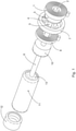
- Figs 1 to 3 show one phase of a two or three position switch driven by a planetary gear drive in disconnected, connected and earthed position, respectively.
- both the carrier 3 of the planetary cogwheels and the hollow cogwheel 7 are latched or locked against rotation.
- the carrier 3 of the planetary cogwheels is unlatched while the hollow cogwheel 7 is further latched.
- the main spring 1 (also termed first spring) can rotate the carrier 3 of the planetary cogwheels, which then rotates the sun cogwheel 5 and the shaft 6 that is fixed to the sun cogwheel 5 with one end.
- shaft 6 is connected to the piston 13 or a lever of a three position switch (not shown) by a threaded connection, so that the rotation of the shaft 6, driven by shaft 2 that is itself fixedly connected to the carrier 3.
- the rotation of the shaft 6 results in a linear motion of the piston 13 (or rotation of a blade in case of lever position switch) from the earthed position (as shown in Fig. 3 ) to the disconnected position (as shown in Fig. 1 ), or from the disconnected position to the connected position (as shown in Fig 2 ).
- the shaft 6 has to be made from an insulating material.
- auxiliary spring 8 (also termed second spring) is charged by the above described rotation. Its outer end is fixed.
- the threaded connection of the shaft 6 to the piston 13 can be a high-helix thread so that the piston can be moved with a relatively high speed. This enables the switch to connect on a short-circuit without being damaged by excessive pre-arcing; a so-called making ability.
- the carrier 3 of the planetary cogwheels is latched when the desired position of the piston is reached.
- the total rotation of the shaft 6 from one position to the next can be one rotation, less than one or more than one rotation.
- the hollow cogwheel 7 is unlatched while the carrier 3 of the planetary cogwheels is further latched.
- the auxiliary spring 8 can rotate the shaft 6 in the opposite direction compared to the previously described rotation driven by the main spring 1.
- the rotation driven by the auxiliary 8 results in a linear motion of the piston 13 from the connected position (as shown Fig.
- the threaded connection of the shaft 6 can as described above be a high-helix thread so that the piston (or a blade in case of a lever position switch) can be moved with a relatively high speed. This enables the switch to earth on a short-circuit without being damaged by excessive pre-arcing; a so-called making ability.
- the hollow cogwheel 7 is latched when the desired position of the piston is reached.
- the total rotation of the shaft 6 from one position to the next can be one rotation, less than one or more than one rotation.
- the main spring 1 can be recharged by a rotation of its outer end.
- the planetary gear drive can additionally be used for more that one phase.
- wheels 20 and a corresponding chain or toothed belt 21 mechanically connect the three phases so that they are operated in parallel.
- Figs. 5 and 6 show a three phase circuit breaker (CB) with vacuum interrupters (VI) as a further advantageous application of the planetary gear drive (here that can be also a single or a two phase breaker).
- the main spring 1 is a closing spring here. Its rotation results in a rotation of the crankshaft 30, a closing motion of the Vls and a charging of the auxiliary spring 8, which is an opening spring here.
- Fig. 5 shows the open position.
- the crankshaft is in the vicinity of the bottom dead end of its cranks so that the Vls are open.
- Fig. 6 shows the closed position.
- the crankshaft is in the vicinity of the top dead end (or a bit above to get a self back-movement locking function) of its cranks so that the Vls are closed and the contact springs (not shown; inside the pushrods) are compressed.
- the end of the closing operation can be defined by a fixedly installed limit stop shortly after the top dead end of the crankshaft. The force of the pushrods will then latch the closed position of the CB.
- the planetary gear drive can also be used for load break switches.
- the planetary gear drive can also be used for HV and LV equipment
- the main axis of the drive can be in line with the main axis of the switch, so that compact designs of complete switches including the mechanical drives are possible and derived from it the switchgear will be smaller.
- the switch does not require means for driving forth and back - the rotation of springs and main drive parts is always the same. This reduces the complexity of the switch, and so also overall costs and size.
- a planetary gear system is used for driving a two or three position switching device such as an interruption device e.g. a vacuum circuit breaker with springs, for obtaining a small and less complex in-axis design.
- an interruption device e.g. a vacuum circuit breaker with springs
Landscapes
- Driving Mechanisms And Operating Circuits Of Arc-Extinguishing High-Tension Switches (AREA)
Priority Applications (2)
| Application Number | Priority Date | Filing Date | Title |
|---|---|---|---|
| EP20195067.2A EP3965131A1 (fr) | 2020-09-08 | 2020-09-08 | Interrupteur à deux ou trois positions à basse, moyenne ou haute tension |
| PCT/EP2021/072495 WO2022053255A1 (fr) | 2020-09-08 | 2021-08-12 | Commutateur à deux ou trois positions, basse, moyenne ou haute tension |
Applications Claiming Priority (1)
| Application Number | Priority Date | Filing Date | Title |
|---|---|---|---|
| EP20195067.2A EP3965131A1 (fr) | 2020-09-08 | 2020-09-08 | Interrupteur à deux ou trois positions à basse, moyenne ou haute tension |
Publications (1)
| Publication Number | Publication Date |
|---|---|
| EP3965131A1 true EP3965131A1 (fr) | 2022-03-09 |
Family
ID=72432736
Family Applications (1)
| Application Number | Title | Priority Date | Filing Date |
|---|---|---|---|
| EP20195067.2A Withdrawn EP3965131A1 (fr) | 2020-09-08 | 2020-09-08 | Interrupteur à deux ou trois positions à basse, moyenne ou haute tension |
Country Status (2)
| Country | Link |
|---|---|
| EP (1) | EP3965131A1 (fr) |
| WO (1) | WO2022053255A1 (fr) |
Families Citing this family (1)
| Publication number | Priority date | Publication date | Assignee | Title |
|---|---|---|---|---|
| CN115985712B (zh) * | 2023-03-20 | 2023-05-12 | 广东金晖隆开关有限公司 | 一种气体绝缘环网柜中的双断口三工位隔离开关 |
Citations (4)
| Publication number | Priority date | Publication date | Assignee | Title |
|---|---|---|---|---|
| DE859778C (de) * | 1950-10-07 | 1952-12-15 | Siemens Ag | Antriebsvorrichtung fuer das bewegliche Schaltstueck von Hochspannungsschaltern |
| AT339417B (de) * | 1974-04-25 | 1977-10-25 | Naimer H L | Vorrichtung zur entkupplung einer schalterantriebswelle |
| US20030089683A1 (en) * | 2000-02-03 | 2003-05-15 | Per-Olof Thuresson | Circuit breaker |
| DE102016214544A1 (de) * | 2016-08-05 | 2018-02-08 | Siemens Aktiengesellschaft | Getriebe zwischen einem bewegbaren Schaltkontakt und einem Antrieb eines Leistungsschalters |
Family Cites Families (1)
| Publication number | Priority date | Publication date | Assignee | Title |
|---|---|---|---|---|
| CZ290316B6 (cs) * | 1995-11-20 | 2002-07-17 | Ivep A. S. | Pohonová jednotka, zejména elektrických spínacích přístrojů |
-
2020
- 2020-09-08 EP EP20195067.2A patent/EP3965131A1/fr not_active Withdrawn
-
2021
- 2021-08-12 WO PCT/EP2021/072495 patent/WO2022053255A1/fr not_active Ceased
Patent Citations (4)
| Publication number | Priority date | Publication date | Assignee | Title |
|---|---|---|---|---|
| DE859778C (de) * | 1950-10-07 | 1952-12-15 | Siemens Ag | Antriebsvorrichtung fuer das bewegliche Schaltstueck von Hochspannungsschaltern |
| AT339417B (de) * | 1974-04-25 | 1977-10-25 | Naimer H L | Vorrichtung zur entkupplung einer schalterantriebswelle |
| US20030089683A1 (en) * | 2000-02-03 | 2003-05-15 | Per-Olof Thuresson | Circuit breaker |
| DE102016214544A1 (de) * | 2016-08-05 | 2018-02-08 | Siemens Aktiengesellschaft | Getriebe zwischen einem bewegbaren Schaltkontakt und einem Antrieb eines Leistungsschalters |
Also Published As
| Publication number | Publication date |
|---|---|
| WO2022053255A1 (fr) | 2022-03-17 |
Similar Documents
| Publication | Publication Date | Title |
|---|---|---|
| US9082561B2 (en) | Medium voltage circuit breaker arrangement operated by a transmission mechanism | |
| US12014890B2 (en) | High-voltage circuit breaker system | |
| EP3965131A1 (fr) | Interrupteur à deux ou trois positions à basse, moyenne ou haute tension | |
| US9275807B2 (en) | Interlock system for switchgear | |
| CN219226152U (zh) | 一种带强制解锁结构的隔离开关 | |
| CN219476528U (zh) | 一种24kv固体绝缘开关柜联锁机构 | |
| EP3482408B1 (fr) | Dispositif rapide de connecteur de terre pour applications haute tension | |
| CN201829404U (zh) | 气体绝缘金属封闭开关设备三工位操作及联锁装置 | |
| AU2003261668B2 (en) | Drive mechanism for switching installation and method for operating it | |
| US20260011513A1 (en) | Operating mechanism for a switchgear device | |
| US10600587B2 (en) | Electrical switching apparatus and transfer assembly therefor | |
| US5772009A (en) | Operating mechanism for switches and fault interrupters | |
| EP3951821B1 (fr) | Actionnement pour un disjoncteur à vide à basse, moyenne et haute tension | |
| EP2093780A1 (fr) | Unité de commande de ressort, dispositif de commande pour appareil de commutation électrique et procédé de chargement et/ou déchargement d'un ressort dans un dispositif de fonctionnement pour un appareil de commutation électrique | |
| CN119361345B (zh) | 一种用于三相不平衡断路器的换相结构 | |
| EP3968349A1 (fr) | Commande d'un commutateur à basse, moyenne ou haute tension | |
| JP5358513B2 (ja) | スイッチギヤ | |
| US20240312731A1 (en) | Actuating mechanism for a device | |
| JP2522687Y2 (ja) | 遮断器用電動ばね操作器 | |
| CA2994123C (fr) | Enceinte electrique et ensemble de commutation et ensemble de transfert correspondant | |
| CN102456503A (zh) | 气体绝缘金属封闭开关设备三工位操作及联锁装置 | |
| CN118737749A (zh) | 一种用于真空负荷开关的弹簧操作装置 | |
| CN201084578Y (zh) | 断路器机械闭锁机构 | |
| KR20090107842A (ko) | 가스절연 개폐장치 |
Legal Events
| Date | Code | Title | Description |
|---|---|---|---|
| PUAI | Public reference made under article 153(3) epc to a published international application that has entered the european phase |
Free format text: ORIGINAL CODE: 0009012 |
|
| STAA | Information on the status of an ep patent application or granted ep patent |
Free format text: STATUS: THE APPLICATION HAS BEEN PUBLISHED |
|
| AK | Designated contracting states |
Kind code of ref document: A1 Designated state(s): AL AT BE BG CH CY CZ DE DK EE ES FI FR GB GR HR HU IE IS IT LI LT LU LV MC MK MT NL NO PL PT RO RS SE SI SK SM TR |
|
| STAA | Information on the status of an ep patent application or granted ep patent |
Free format text: STATUS: REQUEST FOR EXAMINATION WAS MADE |
|
| 17P | Request for examination filed |
Effective date: 20220818 |
|
| RBV | Designated contracting states (corrected) |
Designated state(s): AL AT BE BG CH CY CZ DE DK EE ES FI FR GB GR HR HU IE IS IT LI LT LU LV MC MK MT NL NO PL PT RO RS SE SI SK SM TR |
|
| STAA | Information on the status of an ep patent application or granted ep patent |
Free format text: STATUS: EXAMINATION IS IN PROGRESS |
|
| 17Q | First examination report despatched |
Effective date: 20240202 |
|
| GRAP | Despatch of communication of intention to grant a patent |
Free format text: ORIGINAL CODE: EPIDOSNIGR1 |
|
| STAA | Information on the status of an ep patent application or granted ep patent |
Free format text: STATUS: GRANT OF PATENT IS INTENDED |
|
| RIC1 | Information provided on ipc code assigned before grant |
Ipc: H01H 33/02 20060101ALN20241118BHEP Ipc: H01H 3/46 20060101ALN20241118BHEP Ipc: H01H 3/36 20060101ALN20241118BHEP Ipc: H01H 33/42 20060101ALN20241118BHEP Ipc: H01H 33/40 20060101ALN20241118BHEP Ipc: H01H 31/32 20060101ALN20241118BHEP Ipc: H01H 31/28 20060101ALN20241118BHEP Ipc: H01H 3/30 20060101ALN20241118BHEP Ipc: H01H 33/666 20060101ALN20241118BHEP Ipc: H01H 3/40 20060101AFI20241118BHEP |
|
| RIC1 | Information provided on ipc code assigned before grant |
Ipc: H01H 33/02 20060101ALN20241205BHEP Ipc: H01H 3/46 20060101ALN20241205BHEP Ipc: H01H 3/36 20060101ALN20241205BHEP Ipc: H01H 33/42 20060101ALN20241205BHEP Ipc: H01H 33/40 20060101ALN20241205BHEP Ipc: H01H 31/32 20060101ALN20241205BHEP Ipc: H01H 31/28 20060101ALN20241205BHEP Ipc: H01H 3/30 20060101ALN20241205BHEP Ipc: H01H 33/666 20060101ALN20241205BHEP Ipc: H01H 3/40 20060101AFI20241205BHEP |
|
| INTG | Intention to grant announced |
Effective date: 20241219 |
|
| STAA | Information on the status of an ep patent application or granted ep patent |
Free format text: STATUS: THE APPLICATION IS DEEMED TO BE WITHDRAWN |
|
| 18D | Application deemed to be withdrawn |
Effective date: 20250423 |