EP3965242A1 - Rampe mit variabler geometrie für elektrische kabelbäume und luftfahrzeug mit mindestens einer solchen rampe - Google Patents
Rampe mit variabler geometrie für elektrische kabelbäume und luftfahrzeug mit mindestens einer solchen rampe Download PDFInfo
- Publication number
- EP3965242A1 EP3965242A1 EP21192917.9A EP21192917A EP3965242A1 EP 3965242 A1 EP3965242 A1 EP 3965242A1 EP 21192917 A EP21192917 A EP 21192917A EP 3965242 A1 EP3965242 A1 EP 3965242A1
- Authority
- EP
- European Patent Office
- Prior art keywords
- ramp
- bar
- tube
- electrical harness
- parts
- Prior art date
- Legal status (The legal status is an assumption and is not a legal conclusion. Google has not performed a legal analysis and makes no representation as to the accuracy of the status listed.)
- Granted
Links
Images


Classifications
-
- H—ELECTRICITY
- H02—GENERATION; CONVERSION OR DISTRIBUTION OF ELECTRIC POWER
- H02G—INSTALLATION OF ELECTRIC CABLES OR LINES, OR OF COMBINED OPTICAL AND ELECTRIC CABLES OR LINES
- H02G3/00—Installations of electric cables or lines or protective tubing therefor in or on buildings, equivalent structures or vehicles
- H02G3/30—Installations of cables or lines on walls, floors or ceilings
- H02G3/32—Installations of cables or lines on walls, floors or ceilings using mounting clamps
-
- B—PERFORMING OPERATIONS; TRANSPORTING
- B60—VEHICLES IN GENERAL
- B60R—VEHICLES, VEHICLE FITTINGS, OR VEHICLE PARTS, NOT OTHERWISE PROVIDED FOR
- B60R16/00—Electric or fluid circuits specially adapted for vehicles and not otherwise provided for; Arrangement of elements of electric or fluid circuits specially adapted for vehicles and not otherwise provided for
- B60R16/02—Electric or fluid circuits specially adapted for vehicles and not otherwise provided for; Arrangement of elements of electric or fluid circuits specially adapted for vehicles and not otherwise provided for electric constitutive elements
- B60R16/0207—Wire harnesses
- B60R16/0215—Protecting, fastening and routing means therefor
-
- H—ELECTRICITY
- H02—GENERATION; CONVERSION OR DISTRIBUTION OF ELECTRIC POWER
- H02G—INSTALLATION OF ELECTRIC CABLES OR LINES, OR OF COMBINED OPTICAL AND ELECTRIC CABLES OR LINES
- H02G3/00—Installations of electric cables or lines or protective tubing therefor in or on buildings, equivalent structures or vehicles
- H02G3/02—Details
- H02G3/04—Protective tubing or conduits, e.g. cable ladders or cable troughs
- H02G3/0456—Ladders or other supports
-
- H—ELECTRICITY
- H02—GENERATION; CONVERSION OR DISTRIBUTION OF ELECTRIC POWER
- H02G—INSTALLATION OF ELECTRIC CABLES OR LINES, OR OF COMBINED OPTICAL AND ELECTRIC CABLES OR LINES
- H02G3/00—Installations of electric cables or lines or protective tubing therefor in or on buildings, equivalent structures or vehicles
- H02G3/02—Details
- H02G3/04—Protective tubing or conduits, e.g. cable ladders or cable troughs
- H02G3/0462—Tubings, i.e. having a closed section
-
- B—PERFORMING OPERATIONS; TRANSPORTING
- B60—VEHICLES IN GENERAL
- B60Y—INDEXING SCHEME RELATING TO ASPECTS CROSS-CUTTING VEHICLE TECHNOLOGY
- B60Y2200/00—Type of vehicle
- B60Y2200/50—Aeroplanes, Helicopters
Definitions
- the present application relates to a ramp with variable geometry for an electrical harness as well as to an aircraft comprising at least one such ramp.
- a ramp 10 supporting an electrical harness 12 comprises a rectilinear bar 14, of fixed length and connected at each of its ends to a support (not shown) by means of fixing elements 14.1, 14.2, as well as several supports 16, integral with the bar 14, making it possible to connect the electrical harness 12 to the bar 14 using clamps 18 of the self-locking type, for example.
- the supports 16 and the bar 14 form a single piece.
- the length L0 of the bar 14 is fixed, the number of supports 16 is fixed, their position and orientation with respect to the bar 14 are fixed.
- the distance separating the fixing elements 14.1, 14.2 varying according to the positioning of the bar 14 in the aircraft, the length of the bar 14 varies from one ramp to another.
- the path followed by the electrical harness varying according to the positioning of the electrical harness in the aircraft, the orientation and positioning of the supports vary from one ramp to another.
- each ramp model having a bar of a certain length and supports 16 positioned and oriented in a certain way.
- the present invention aims to remedy all or part of the drawbacks of the prior art.
- the subject of the invention is a ramp for an electrical harness comprising a rectilinear bar, extending in a longitudinal direction, having first and second ends configured to be connected in a removable manner to at least one support in operation as well as several supports distributed along the bar, connected to the latter, to which is connected at least one electrical harness in operation.
- the bar comprises at least two parts configured to slide relative to each other in the longitudinal direction, a first part being connected to the first end and a second part being connected to the second part, to the at least one of the first and second parts comprising a tube having an outer surface provided with longitudinal grooves which extend over almost the entire length of the tube and are distributed homogeneously over its entire circumference.
- the length of the bar of the ramp can vary and be adjusted according to the distance separating the fixing elements provided for connecting the first and second ends of the bar to the support.
- at least one support is connected to one of the parts of the bar by a removable connection.
- the bar comprises a first part comprising the first end, a second part comprising the second end as well as an intermediate part inserted between the first and second sliding parts with respect to at least one of the first and second parts.
- the first and second parts are identical and each comprise a tube having an outer surface, an inner surface as well as a first open end via which the intermediate part is introduced, the latter having an outer surface allowing it to slide in the tube of the first or second part.
- the outer surface of the intermediate part has a circular cross section, the inner surface of the tube of the first or second part having a circular cross section identical to that of the outer surface of the intermediate part.
- the ramp comprises a sealing gasket secured to the first or second part and positioned in the tube, on the inner surface, close to its first end.
- the support is made in a single piece and comprises a first zone comprising a surface having a shape complementary to that of the outer surface of the tube of the first or second part of the bar to connect, in a removable manner, the support and the first or second part.
- the support comprises two identical wings, positioned in transverse planes in operation and spaced apart from each other, as well as at least one junction element for connecting the two wings, each wing comprising a first edge in the form of an arc of a circle presenting a shape complementary to that of the outer surface of the tube of each of the first and second parts.
- the support comprises first and second jaws as well as a connecting element making it possible to connect the first and second jaws so that they enclose the first or second part of the bar.
- the invention also relates to an aircraft comprising at least one harness ramp according to one of the preceding characteristics.
- a ramp 20 positioned in a vehicle such as an aircraft, makes it possible to support an electrical harness H (visible on the figure 5 , 9 and 16 ).
- electrical harness one or more electrical cable(s) grouped together along a cable path.
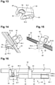
- the ramp 20 comprises a substantially rectilinear bar 22 having first and second ends 22.1, 22.2 detachably connected to at least one support 24 (visible on the figure 16 ) by fixing elements 26.
- the bar 22 comprises, at each of its first and second ends 22.1, 22.2, an eyelet 28 (visible on the figure 5 ).
- Each of the fixing elements 26 is in the form of a screw passing through the eyelet 28 and being screwed into the support 24, as illustrated in the figure 16 .
- the invention is not limited to this embodiment to ensure the connection between the bar 22 and the support 24.
- a longitudinal direction corresponds to a direction passing through the fixing elements 26 provided at the first and second ends 22.1, 22.2 of the bar 22 of the ramp 20.
- a transverse plane is a plane perpendicular to the longitudinal direction .
- the bar 22 extends in the longitudinal direction and has a length L0, dimension taken in the longitudinal direction, equal to the distance separating the fixing elements 26 provided at the first and second ends 22.1, 22.2 of the bar 22.
- the bar 22 comprises at least two parts 30, 32 configured to slide relative to each other in the longitudinal direction, a first part 30 being connected, directly or indirectly, to the first end 22.1 and a second part 32 being linked, directly or indirectly, to the second part 22.2. Thanks to the sliding between the first and second parts 30, 32, the length L0 of the bar 22 of the ramp 20 can vary and be adjusted to the distance separating the fixing elements 26 provided at the first and second ends 22.1, 22.2 of the bar 22.
- the bar 22 comprises a first part 30 comprising the first end 22.1, a second part 32 comprising the second end 22.2 as well as a third part called the intermediate part 34 inserted between the first and second parts 30, 32 sliding with respect to at least one of the first and second parts 30, 32.
- each of the first and second parts 30, 32 is configured to slide relative to the intermediate part 34.
- the second part 32 and the intermediate part 34 are fixed relative to each other and the first part 30 is configured to slide relative to the intermediate part 34.
- the first and second parts 30, 32 are identical. As illustrated on the figure 16 , each of the first and second parts 30, 32 comprises a tube 36 having an outer surface S36Ext, an inner surface S36Int of substantially constant cross-section along its length, a first open end 36.1, via which the intermediate part 34 is inserted, as well as a second closed end 36.2 to which the eyelet 28 is connected.
- the intermediate part 34 is an elongated element and comprises an outer surface S34Ext of substantially constant cross section along its length and approximately equal to the cross section of the inner surface S36Int of the tube 36 to allow the intermediate part 34 to slide in the tube 36 of the first or second part 30, 32.
- the intermediate part 34 can be solid or hollow.
- the cross section of the outer surface S34Ext of the intermediate part 34 and the cross section of the inner surface S36Int of the tube 36 of the first or second part 30, 32 have an identical and circular cross section. That solution allows the first or second part 30, 32 or both to pivot relative to the intermediate part 34 around a pivot axis coinciding with the axis of revolution of the intermediate part 34 or of the tube 36 of the first or second part 30, 32.
- a seal 38 is interposed between the moving parts of the bar 22.
- a seal 38 is secured to the first or second part 30, 32 and positioned in the tube 36, on the inner surface S36Int, close to its first end 36.1.
- This seal 38 limits the infiltration of fluid inside the tube 36. It also makes it possible to absorb any vibrations.
- the seal 38 has a longitudinal slot 38.1 to allow air to enter or leave the tube 36 during the sliding of the first or second part 30, 32 and the intermediate part 34 one compared to the other. This slot 38.1 is configured to allow the passage of air and limit the passage of a liquid inside the tube 36.
- the ramp 30 comprises several supports 40 distributed along the bar 22, connected to the latter.
- the electrical harness H is connected to the various supports 40 by links 42 identical to those of the prior art for example.
- the supports 40 are positioned on the first and second parts 30, 32 and are not positioned on the intermediate part 34 to allow the sliding of at least one of the first and second parts 30, 32 with respect to the part intermediate 34.
- At least one support 40 is connected to one of the parts 30, 32, 34 of the bar 22 by a removable connection to allow the positioning and orientation of each support 40 to be adjusted on the bar 22 of the ramp 20.
- the support 40 is made in one piece.
- the outer surface S36Ext of the tube 36 of each of the first and second parts 30, 32 has longitudinal grooves 44 which extend over almost the entire length of the tube 36 and are distributed evenly over its entire circumference.
- each of the first and second parts 30, 32 comprises twelve splines 44.
- the support 40 comprises a first zone 40.1 configured to allow it to be connected in a removable manner with the bar 22 of the ramp 20 as well as a second zone 40.2 configured to receive the electrical harness H and position it according to a desired cable path, a link 42 being provided to connect the electrical harness H and the support 40.
- the first zone 40.1 of the support 40 comprises a surface having a shape complementary to that of the outer surface S36Ext of the tube 36 of each of the first and second parts 30, 32 to connect it in a removable manner to the first or second part 30, 32 of bar 22.
- the support 40 comprises two identical flanges 46, 46', positioned in transverse planes in operation and spaced apart from each other, each flange 46, 46' comprising a first edge 48.1 in an arc of a circle having a shape complementary to that of the outer surface S36Ext of the tube 36 of each of the first and second parts 30, 32 as well as a second edge 48.2, for example in V, forming a housing for an electrical harness H.
- the support 40 comprises at least one junction element to connect the two wings 46, 46'.
- the support 40 comprises a central junction element 50 having a curved surface S50, with an arcuate section and positioned in the extension of the first edges 48.1 of the two wings 46, 46', as well as two junction elements side 52.1, 52.2 arranged on either side of the central junction element 50, for example of cylindrical shape, allowing to hang a link 42 such as a self-locking clamp for example.
- each of the supports 40 can be clipped onto the first or second part 30, 32 by deforming elastically and/or can be slipped on from one end of the first or second part 30, 32.
- the support 40 can be oriented in different ways around the first or second part 30, 32 and positioned at different positions along the first or second part 30, 32.
- two supports 40 can be positioned diametrically opposite on the first or second part 30, 32 and make it possible to support two electrical harnesses arranged on either side of the first or second part 30, 32.
- each support 40 is immobilized in rotation with respect to the first or second part 30, 32 thanks to the grooves 44, 44' and in translation along the first or second part 30, 32 thanks to the friction between the support 40 and the first or second part 30, 32.
- the support 40' comprises first and second jaws 54.1, 54.2 as well as a connecting element 56 making it possible to connect the first and second jaws 54.1, 54.2 so that they grip the first or second part 30, 32.
- the first and second parts 30, 32 may be identical to those of the first embodiment and have grooves.
- the first and second jaws 54.1, 54.2 each have a curved portion 58 provided with grooves as well as a through hole 60 to house the connecting element 56.
- the electrical harness H is connected to the support 40' by a link such as a rigid collar for example, itself connected to the support 40' thanks to the connecting element 56.
- the invention is not limited to the first and second embodiments for the supports. Other solutions are possible.
- the supports are not necessarily positioned on the first and second parts 30, 32.
- some supports 40 can be positioned on the first or second part 30, 32 while at least one other support 40" is positioned at one of the first and second ends 22.1, 22.2 of the bar 22 of the ramp 20 and connected to the latter by means of one of the fastening elements 26.
- first model corresponding to the first and second parts 30, 32 a second model corresponding to the intermediate part 34 as well as a third model corresponding to the supports 40, it is possible to obtain a large number of variants of ramps 20 each having an adaptable length and each provided with supports whose orientation and position can be adapted.
Landscapes
- Engineering & Computer Science (AREA)
- Architecture (AREA)
- Civil Engineering (AREA)
- Structural Engineering (AREA)
- Mechanical Engineering (AREA)
- Supports For Pipes And Cables (AREA)
- Details Of Indoor Wiring (AREA)
- Installation Of Indoor Wiring (AREA)
Applications Claiming Priority (1)
| Application Number | Priority Date | Filing Date | Title |
|---|---|---|---|
| FR2008925A FR3113788A1 (fr) | 2020-09-03 | 2020-09-03 | Rampe à géométrie variable pour harnais électrique et aéronef comportant au moins une telle rampe |
Publications (2)
| Publication Number | Publication Date |
|---|---|
| EP3965242A1 true EP3965242A1 (de) | 2022-03-09 |
| EP3965242B1 EP3965242B1 (de) | 2023-06-07 |
Family
ID=73139012
Family Applications (1)
| Application Number | Title | Priority Date | Filing Date |
|---|---|---|---|
| EP21192917.9A Active EP3965242B1 (de) | 2020-09-03 | 2021-08-24 | Rampe mit variabler geometrie für elektrische kabelbäume und luftfahrzeug mit mindestens einer solchen rampe |
Country Status (4)
| Country | Link |
|---|---|
| US (1) | US11518322B2 (de) |
| EP (1) | EP3965242B1 (de) |
| CN (1) | CN114142404A (de) |
| FR (1) | FR3113788A1 (de) |
Cited By (1)
| Publication number | Priority date | Publication date | Assignee | Title |
|---|---|---|---|---|
| FR3146768A1 (fr) * | 2023-03-15 | 2024-09-20 | Airbus Operations (S.A.S.) | Câble électrique équipé d’au moins un espaceur, aéronef comportant au moins un tel câble électrique |
Citations (4)
| Publication number | Priority date | Publication date | Assignee | Title |
|---|---|---|---|---|
| US5388790A (en) * | 1991-02-02 | 1995-02-14 | Deutsche Aerospace Airbus Gmbh | Guide and support frame for electrical conductors in an aircraft |
| FR2962716A1 (fr) * | 2010-07-13 | 2012-01-20 | Airbus Operations Sas | Ensemble de fixation comprenant des rampes pour la fixation de systemes sur des cadres d'aeronef. |
| US20120037418A1 (en) * | 2010-08-10 | 2012-02-16 | Doris Zyrull | Mounting arrangement for mounting systems and aircraft or spacecraft |
| US20150285407A1 (en) * | 2014-04-08 | 2015-10-08 | Airbus Operations (Sas) | Support element for supporting at least one conduit in an aircraft, and corresponding support device |
Family Cites Families (2)
| Publication number | Priority date | Publication date | Assignee | Title |
|---|---|---|---|---|
| DE102009022796B4 (de) * | 2009-05-27 | 2015-12-03 | Airbus Operations Gmbh | Vorrichtung zum Verlegen eines in einem Flugzeug installierten Kabelstrangs |
| EP2787586B1 (de) * | 2013-04-05 | 2016-08-10 | Airbus Operations GmbH | Installationsanordnung zum Überbrücken eines Kabelbaums oder dergleichen zwischen zwei Flugzeugstrukturelementen |
-
2020
- 2020-09-03 FR FR2008925A patent/FR3113788A1/fr not_active Ceased
-
2021
- 2021-08-24 EP EP21192917.9A patent/EP3965242B1/de active Active
- 2021-09-01 CN CN202111019254.4A patent/CN114142404A/zh active Pending
- 2021-09-01 US US17/463,803 patent/US11518322B2/en active Active
Patent Citations (4)
| Publication number | Priority date | Publication date | Assignee | Title |
|---|---|---|---|---|
| US5388790A (en) * | 1991-02-02 | 1995-02-14 | Deutsche Aerospace Airbus Gmbh | Guide and support frame for electrical conductors in an aircraft |
| FR2962716A1 (fr) * | 2010-07-13 | 2012-01-20 | Airbus Operations Sas | Ensemble de fixation comprenant des rampes pour la fixation de systemes sur des cadres d'aeronef. |
| US20120037418A1 (en) * | 2010-08-10 | 2012-02-16 | Doris Zyrull | Mounting arrangement for mounting systems and aircraft or spacecraft |
| US20150285407A1 (en) * | 2014-04-08 | 2015-10-08 | Airbus Operations (Sas) | Support element for supporting at least one conduit in an aircraft, and corresponding support device |
Cited By (2)
| Publication number | Priority date | Publication date | Assignee | Title |
|---|---|---|---|---|
| FR3146768A1 (fr) * | 2023-03-15 | 2024-09-20 | Airbus Operations (S.A.S.) | Câble électrique équipé d’au moins un espaceur, aéronef comportant au moins un tel câble électrique |
| US12603197B2 (en) | 2023-03-15 | 2026-04-14 | Airbus Operations Sas | Electric cable equipped with at least one spacer, aircraft comprising at least one such electric cable |
Also Published As
| Publication number | Publication date |
|---|---|
| EP3965242B1 (de) | 2023-06-07 |
| FR3113788A1 (fr) | 2022-03-04 |
| US11518322B2 (en) | 2022-12-06 |
| US20220063525A1 (en) | 2022-03-03 |
| CN114142404A (zh) | 2022-03-04 |
Similar Documents
| Publication | Publication Date | Title |
|---|---|---|
| EP3553331B1 (de) | Verbindungsvorrichtung, die zwischen mindestens zwei teilen schwenkbar ist, luftfahrzeug, das eine abdeckung umfasst, die mit dieser schwenkbaren verbindungsvorrichtung ausgestattet ist | |
| FR2783301A1 (fr) | Raccord etanche a geometrie variable | |
| EP3965242B1 (de) | Rampe mit variabler geometrie für elektrische kabelbäume und luftfahrzeug mit mindestens einer solchen rampe | |
| FR3074557A1 (fr) | Dispositif de maintien d'au moins un isolant sur un conduit, conduit equipe dudit dispositif de maintien | |
| FR2697893A1 (fr) | Collier pour le raccordement amovible de deux canalisations. | |
| FR3075307A1 (fr) | Dispositif de fixation | |
| FR3054262B1 (fr) | Ligne d'echappement d'un vehicule dotee d'un batteur | |
| WO1998028180A1 (fr) | Structure de caisse de vehicule automobile comportant des moyens d'assemblage perfectionnes | |
| FR2975143A1 (fr) | Dispositif permettant de regler la position angulaire d'un organe, de facon a garantir la liaison de ce dernier avec un support selon un plan de contact d'orientation predeterminee. | |
| FR2674491A1 (fr) | Dispositif de positionnement pour raccords de canalisations d'installations hydrauliques pour vehicules automobiles, notamment pour groupes de servodirection hydraulique. | |
| EP2022921B1 (de) | Befestigungsvorrichtung für einen Mitnehmer einer Fensterscheibe bestehend aus Schraubenmuttern und Schrauben | |
| FR2594204A1 (fr) | Dispositif destine a fixer un tube sur un mur | |
| FR2640349A1 (fr) | Collier de fixation de tuyauteries | |
| FR3091911A1 (fr) | Dispositif de liaison pivotante entre au moins deux pièces, aéronef comprenant un capot équipé dudit dispositif de liaison pivotante | |
| FR2616182A1 (fr) | Raccord tubulaire entre arceaux de protection de vehicule | |
| BE1012315A6 (fr) | Support porte-bagages a reglages multiples pour vehicules. | |
| FR2756204A1 (fr) | Dispositif de pose d'un joint d'etancheite | |
| FR2801001A1 (fr) | Dispositif de positionnement de d'immobilisation d'un conduit secondaire destine a etre fixe intimement a un conduit principal | |
| FR3134612A1 (fr) | Dispositif de raccordement entre deux conduits comprenant une liaison rotule et canalisation comprenant ledit dispositif de raccordement | |
| FR3014484B1 (fr) | Ecran de protection thermique pour dispositif de sortie de gaz d'echappement de vehicule automobile | |
| EP1431647B1 (de) | Anschlussanordnung eines zu einer Aufpumpflasche gehörenden Aufstechkopfes einer Sicherheitseinrichtung | |
| WO2000015477A1 (fr) | Systeme d'essuie-glace comportant des moyens de fixation par bride d'un support moteur sur une traverse tubulaire | |
| FR3075896A1 (fr) | Ensemble pour la fixation d'un cable de boite de vitesses | |
| FR3162253A1 (fr) | Ensemble permettant un assemblage dans un espace encombre d’un accessoire sur un support | |
| EP4083533A1 (de) | Fluidanschluss zwischen zwei leitungen zur durchflussregulierung |
Legal Events
| Date | Code | Title | Description |
|---|---|---|---|
| PUAI | Public reference made under article 153(3) epc to a published international application that has entered the european phase |
Free format text: ORIGINAL CODE: 0009012 |
|
| STAA | Information on the status of an ep patent application or granted ep patent |
Free format text: STATUS: THE APPLICATION HAS BEEN PUBLISHED |
|
| AK | Designated contracting states |
Kind code of ref document: A1 Designated state(s): AL AT BE BG CH CY CZ DE DK EE ES FI FR GB GR HR HU IE IS IT LI LT LU LV MC MK MT NL NO PL PT RO RS SE SI SK SM TR |
|
| STAA | Information on the status of an ep patent application or granted ep patent |
Free format text: STATUS: REQUEST FOR EXAMINATION WAS MADE |
|
| 17P | Request for examination filed |
Effective date: 20220831 |
|
| RBV | Designated contracting states (corrected) |
Designated state(s): AL AT BE BG CH CY CZ DE DK EE ES FI FR GB GR HR HU IE IS IT LI LT LU LV MC MK MT NL NO PL PT RO RS SE SI SK SM TR |
|
| GRAP | Despatch of communication of intention to grant a patent |
Free format text: ORIGINAL CODE: EPIDOSNIGR1 |
|
| STAA | Information on the status of an ep patent application or granted ep patent |
Free format text: STATUS: GRANT OF PATENT IS INTENDED |
|
| RIC1 | Information provided on ipc code assigned before grant |
Ipc: F16L 3/24 20060101ALI20230113BHEP Ipc: F16L 3/12 20060101ALI20230113BHEP Ipc: F16L 3/10 20060101ALI20230113BHEP Ipc: H02G 3/00 20060101ALI20230113BHEP Ipc: H02G 3/32 20060101AFI20230113BHEP Ipc: H02G 3/04 20060101ALN20230113BHEP |
|
| RIC1 | Information provided on ipc code assigned before grant |
Ipc: H02G 3/04 20060101ALN20230126BHEP Ipc: F16L 3/24 20060101ALI20230126BHEP Ipc: F16L 3/12 20060101ALI20230126BHEP Ipc: F16L 3/10 20060101ALI20230126BHEP Ipc: H02G 3/00 20060101ALI20230126BHEP Ipc: H02G 3/32 20060101AFI20230126BHEP |
|
| RIC1 | Information provided on ipc code assigned before grant |
Ipc: H02G 3/04 20060101ALN20230127BHEP Ipc: F16L 3/24 20060101ALI20230127BHEP Ipc: F16L 3/12 20060101ALI20230127BHEP Ipc: F16L 3/10 20060101ALI20230127BHEP Ipc: H02G 3/00 20060101ALI20230127BHEP Ipc: H02G 3/32 20060101AFI20230127BHEP |
|
| GRAS | Grant fee paid |
Free format text: ORIGINAL CODE: EPIDOSNIGR3 |
|
| INTG | Intention to grant announced |
Effective date: 20230213 |
|
| RIN1 | Information on inventor provided before grant (corrected) |
Inventor name: DELPY, M. VINCENT Inventor name: MILLET, M. GERARD |
|
| GRAA | (expected) grant |
Free format text: ORIGINAL CODE: 0009210 |
|
| STAA | Information on the status of an ep patent application or granted ep patent |
Free format text: STATUS: THE PATENT HAS BEEN GRANTED |
|
| AK | Designated contracting states |
Kind code of ref document: B1 Designated state(s): AL AT BE BG CH CY CZ DE DK EE ES FI FR GB GR HR HU IE IS IT LI LT LU LV MC MK MT NL NO PL PT RO RS SE SI SK SM TR |
|
| REG | Reference to a national code |
Ref country code: GB Ref legal event code: FG4D Free format text: NOT ENGLISH |
|
| REG | Reference to a national code |
Ref country code: CH Ref legal event code: EP Ref country code: AT Ref legal event code: REF Ref document number: 1577765 Country of ref document: AT Kind code of ref document: T Effective date: 20230615 |
|
| REG | Reference to a national code |
Ref country code: DE Ref legal event code: R096 Ref document number: 602021002751 Country of ref document: DE |
|
| REG | Reference to a national code |
Ref country code: LT Ref legal event code: MG9D |
|
| REG | Reference to a national code |
Ref country code: NL Ref legal event code: MP Effective date: 20230607 |
|
| PG25 | Lapsed in a contracting state [announced via postgrant information from national office to epo] |
Ref country code: SE Free format text: LAPSE BECAUSE OF FAILURE TO SUBMIT A TRANSLATION OF THE DESCRIPTION OR TO PAY THE FEE WITHIN THE PRESCRIBED TIME-LIMIT Effective date: 20230607 Ref country code: NO Free format text: LAPSE BECAUSE OF FAILURE TO SUBMIT A TRANSLATION OF THE DESCRIPTION OR TO PAY THE FEE WITHIN THE PRESCRIBED TIME-LIMIT Effective date: 20230907 Ref country code: ES Free format text: LAPSE BECAUSE OF FAILURE TO SUBMIT A TRANSLATION OF THE DESCRIPTION OR TO PAY THE FEE WITHIN THE PRESCRIBED TIME-LIMIT Effective date: 20230607 |
|
| REG | Reference to a national code |
Ref country code: AT Ref legal event code: MK05 Ref document number: 1577765 Country of ref document: AT Kind code of ref document: T Effective date: 20230607 |
|
| PG25 | Lapsed in a contracting state [announced via postgrant information from national office to epo] |
Ref country code: RS Free format text: LAPSE BECAUSE OF FAILURE TO SUBMIT A TRANSLATION OF THE DESCRIPTION OR TO PAY THE FEE WITHIN THE PRESCRIBED TIME-LIMIT Effective date: 20230607 Ref country code: NL Free format text: LAPSE BECAUSE OF FAILURE TO SUBMIT A TRANSLATION OF THE DESCRIPTION OR TO PAY THE FEE WITHIN THE PRESCRIBED TIME-LIMIT Effective date: 20230607 Ref country code: LV Free format text: LAPSE BECAUSE OF FAILURE TO SUBMIT A TRANSLATION OF THE DESCRIPTION OR TO PAY THE FEE WITHIN THE PRESCRIBED TIME-LIMIT Effective date: 20230607 Ref country code: LT Free format text: LAPSE BECAUSE OF FAILURE TO SUBMIT A TRANSLATION OF THE DESCRIPTION OR TO PAY THE FEE WITHIN THE PRESCRIBED TIME-LIMIT Effective date: 20230607 Ref country code: HR Free format text: LAPSE BECAUSE OF FAILURE TO SUBMIT A TRANSLATION OF THE DESCRIPTION OR TO PAY THE FEE WITHIN THE PRESCRIBED TIME-LIMIT Effective date: 20230607 Ref country code: GR Free format text: LAPSE BECAUSE OF FAILURE TO SUBMIT A TRANSLATION OF THE DESCRIPTION OR TO PAY THE FEE WITHIN THE PRESCRIBED TIME-LIMIT Effective date: 20230908 |
|
| PG25 | Lapsed in a contracting state [announced via postgrant information from national office to epo] |
Ref country code: FI Free format text: LAPSE BECAUSE OF FAILURE TO SUBMIT A TRANSLATION OF THE DESCRIPTION OR TO PAY THE FEE WITHIN THE PRESCRIBED TIME-LIMIT Effective date: 20230607 |
|
| PG25 | Lapsed in a contracting state [announced via postgrant information from national office to epo] |
Ref country code: SK Free format text: LAPSE BECAUSE OF FAILURE TO SUBMIT A TRANSLATION OF THE DESCRIPTION OR TO PAY THE FEE WITHIN THE PRESCRIBED TIME-LIMIT Effective date: 20230607 |
|
| PG25 | Lapsed in a contracting state [announced via postgrant information from national office to epo] |
Ref country code: IS Free format text: LAPSE BECAUSE OF FAILURE TO SUBMIT A TRANSLATION OF THE DESCRIPTION OR TO PAY THE FEE WITHIN THE PRESCRIBED TIME-LIMIT Effective date: 20231007 |
|
| PG25 | Lapsed in a contracting state [announced via postgrant information from national office to epo] |
Ref country code: SM Free format text: LAPSE BECAUSE OF FAILURE TO SUBMIT A TRANSLATION OF THE DESCRIPTION OR TO PAY THE FEE WITHIN THE PRESCRIBED TIME-LIMIT Effective date: 20230607 Ref country code: SK Free format text: LAPSE BECAUSE OF FAILURE TO SUBMIT A TRANSLATION OF THE DESCRIPTION OR TO PAY THE FEE WITHIN THE PRESCRIBED TIME-LIMIT Effective date: 20230607 Ref country code: RO Free format text: LAPSE BECAUSE OF FAILURE TO SUBMIT A TRANSLATION OF THE DESCRIPTION OR TO PAY THE FEE WITHIN THE PRESCRIBED TIME-LIMIT Effective date: 20230607 Ref country code: PT Free format text: LAPSE BECAUSE OF FAILURE TO SUBMIT A TRANSLATION OF THE DESCRIPTION OR TO PAY THE FEE WITHIN THE PRESCRIBED TIME-LIMIT Effective date: 20231009 Ref country code: IS Free format text: LAPSE BECAUSE OF FAILURE TO SUBMIT A TRANSLATION OF THE DESCRIPTION OR TO PAY THE FEE WITHIN THE PRESCRIBED TIME-LIMIT Effective date: 20231007 Ref country code: EE Free format text: LAPSE BECAUSE OF FAILURE TO SUBMIT A TRANSLATION OF THE DESCRIPTION OR TO PAY THE FEE WITHIN THE PRESCRIBED TIME-LIMIT Effective date: 20230607 Ref country code: CZ Free format text: LAPSE BECAUSE OF FAILURE TO SUBMIT A TRANSLATION OF THE DESCRIPTION OR TO PAY THE FEE WITHIN THE PRESCRIBED TIME-LIMIT Effective date: 20230607 Ref country code: AT Free format text: LAPSE BECAUSE OF FAILURE TO SUBMIT A TRANSLATION OF THE DESCRIPTION OR TO PAY THE FEE WITHIN THE PRESCRIBED TIME-LIMIT Effective date: 20230607 |
|
| PG25 | Lapsed in a contracting state [announced via postgrant information from national office to epo] |
Ref country code: PL Free format text: LAPSE BECAUSE OF FAILURE TO SUBMIT A TRANSLATION OF THE DESCRIPTION OR TO PAY THE FEE WITHIN THE PRESCRIBED TIME-LIMIT Effective date: 20230607 |
|
| REG | Reference to a national code |
Ref country code: DE Ref legal event code: R097 Ref document number: 602021002751 Country of ref document: DE |
|
| PG25 | Lapsed in a contracting state [announced via postgrant information from national office to epo] |
Ref country code: MC Free format text: LAPSE BECAUSE OF FAILURE TO SUBMIT A TRANSLATION OF THE DESCRIPTION OR TO PAY THE FEE WITHIN THE PRESCRIBED TIME-LIMIT Effective date: 20230607 |
|
| PG25 | Lapsed in a contracting state [announced via postgrant information from national office to epo] |
Ref country code: MC Free format text: LAPSE BECAUSE OF FAILURE TO SUBMIT A TRANSLATION OF THE DESCRIPTION OR TO PAY THE FEE WITHIN THE PRESCRIBED TIME-LIMIT Effective date: 20230607 |
|
| PLBE | No opposition filed within time limit |
Free format text: ORIGINAL CODE: 0009261 |
|
| STAA | Information on the status of an ep patent application or granted ep patent |
Free format text: STATUS: NO OPPOSITION FILED WITHIN TIME LIMIT |
|
| PG25 | Lapsed in a contracting state [announced via postgrant information from national office to epo] |
Ref country code: LU Free format text: LAPSE BECAUSE OF NON-PAYMENT OF DUE FEES Effective date: 20230824 |
|
| PG25 | Lapsed in a contracting state [announced via postgrant information from national office to epo] |
Ref country code: LU Free format text: LAPSE BECAUSE OF NON-PAYMENT OF DUE FEES Effective date: 20230824 Ref country code: DK Free format text: LAPSE BECAUSE OF FAILURE TO SUBMIT A TRANSLATION OF THE DESCRIPTION OR TO PAY THE FEE WITHIN THE PRESCRIBED TIME-LIMIT Effective date: 20230607 |
|
| PG25 | Lapsed in a contracting state [announced via postgrant information from national office to epo] |
Ref country code: SI Free format text: LAPSE BECAUSE OF FAILURE TO SUBMIT A TRANSLATION OF THE DESCRIPTION OR TO PAY THE FEE WITHIN THE PRESCRIBED TIME-LIMIT Effective date: 20230607 |
|
| REG | Reference to a national code |
Ref country code: BE Ref legal event code: MM Effective date: 20230831 |
|
| 26N | No opposition filed |
Effective date: 20240308 |
|
| REG | Reference to a national code |
Ref country code: IE Ref legal event code: MM4A |
|
| PG25 | Lapsed in a contracting state [announced via postgrant information from national office to epo] |
Ref country code: SI Free format text: LAPSE BECAUSE OF FAILURE TO SUBMIT A TRANSLATION OF THE DESCRIPTION OR TO PAY THE FEE WITHIN THE PRESCRIBED TIME-LIMIT Effective date: 20230607 Ref country code: IT Free format text: LAPSE BECAUSE OF FAILURE TO SUBMIT A TRANSLATION OF THE DESCRIPTION OR TO PAY THE FEE WITHIN THE PRESCRIBED TIME-LIMIT Effective date: 20230607 |
|
| PG25 | Lapsed in a contracting state [announced via postgrant information from national office to epo] |
Ref country code: IE Free format text: LAPSE BECAUSE OF NON-PAYMENT OF DUE FEES Effective date: 20230824 |
|
| PG25 | Lapsed in a contracting state [announced via postgrant information from national office to epo] |
Ref country code: IE Free format text: LAPSE BECAUSE OF NON-PAYMENT OF DUE FEES Effective date: 20230824 |
|
| PG25 | Lapsed in a contracting state [announced via postgrant information from national office to epo] |
Ref country code: BE Free format text: LAPSE BECAUSE OF NON-PAYMENT OF DUE FEES Effective date: 20230831 |
|
| PG25 | Lapsed in a contracting state [announced via postgrant information from national office to epo] |
Ref country code: BG Free format text: LAPSE BECAUSE OF FAILURE TO SUBMIT A TRANSLATION OF THE DESCRIPTION OR TO PAY THE FEE WITHIN THE PRESCRIBED TIME-LIMIT Effective date: 20230607 |
|
| PG25 | Lapsed in a contracting state [announced via postgrant information from national office to epo] |
Ref country code: BG Free format text: LAPSE BECAUSE OF FAILURE TO SUBMIT A TRANSLATION OF THE DESCRIPTION OR TO PAY THE FEE WITHIN THE PRESCRIBED TIME-LIMIT Effective date: 20230607 |
|
| REG | Reference to a national code |
Ref country code: CH Ref legal event code: PL |
|
| PG25 | Lapsed in a contracting state [announced via postgrant information from national office to epo] |
Ref country code: CH Free format text: LAPSE BECAUSE OF NON-PAYMENT OF DUE FEES Effective date: 20240831 |
|
| PG25 | Lapsed in a contracting state [announced via postgrant information from national office to epo] |
Ref country code: CY Free format text: LAPSE BECAUSE OF FAILURE TO SUBMIT A TRANSLATION OF THE DESCRIPTION OR TO PAY THE FEE WITHIN THE PRESCRIBED TIME-LIMIT; INVALID AB INITIO Effective date: 20210824 |
|
| PG25 | Lapsed in a contracting state [announced via postgrant information from national office to epo] |
Ref country code: HU Free format text: LAPSE BECAUSE OF FAILURE TO SUBMIT A TRANSLATION OF THE DESCRIPTION OR TO PAY THE FEE WITHIN THE PRESCRIBED TIME-LIMIT; INVALID AB INITIO Effective date: 20210824 |
|
| PGFP | Annual fee paid to national office [announced via postgrant information from national office to epo] |
Ref country code: DE Payment date: 20250820 Year of fee payment: 5 |
|
| PGFP | Annual fee paid to national office [announced via postgrant information from national office to epo] |
Ref country code: GB Payment date: 20250820 Year of fee payment: 5 |
|
| PGFP | Annual fee paid to national office [announced via postgrant information from national office to epo] |
Ref country code: FR Payment date: 20250828 Year of fee payment: 5 |
|
| PG25 | Lapsed in a contracting state [announced via postgrant information from national office to epo] |
Ref country code: TR Free format text: LAPSE BECAUSE OF FAILURE TO SUBMIT A TRANSLATION OF THE DESCRIPTION OR TO PAY THE FEE WITHIN THE PRESCRIBED TIME-LIMIT Effective date: 20230607 |