EP3965322B1 - Procédé et dispositif permettant de déterminer une rsrp dans une v2x nr - Google Patents
Procédé et dispositif permettant de déterminer une rsrp dans une v2x nr Download PDFInfo
- Publication number
- EP3965322B1 EP3965322B1 EP20802161.8A EP20802161A EP3965322B1 EP 3965322 B1 EP3965322 B1 EP 3965322B1 EP 20802161 A EP20802161 A EP 20802161A EP 3965322 B1 EP3965322 B1 EP 3965322B1
- Authority
- EP
- European Patent Office
- Prior art keywords
- rsrp
- value
- information
- pssch
- sidelink
- Prior art date
- Legal status (The legal status is an assumption and is not a legal conclusion. Google has not performed a legal analysis and makes no representation as to the accuracy of the status listed.)
- Active
Links
Images










Classifications
-
- H—ELECTRICITY
- H04—ELECTRIC COMMUNICATION TECHNIQUE
- H04B—TRANSMISSION
- H04B17/00—Monitoring; Testing
- H04B17/30—Monitoring; Testing of propagation channels
- H04B17/309—Measuring or estimating channel quality parameters
- H04B17/318—Received signal strength
- H04B17/328—Reference signal received power [RSRP]; Reference signal received quality [RSRQ]
-
- H—ELECTRICITY
- H04—ELECTRIC COMMUNICATION TECHNIQUE
- H04B—TRANSMISSION
- H04B17/00—Monitoring; Testing
- H04B17/30—Monitoring; Testing of propagation channels
- H04B17/309—Measuring or estimating channel quality parameters
- H04B17/347—Path loss
-
- H—ELECTRICITY
- H04—ELECTRIC COMMUNICATION TECHNIQUE
- H04L—TRANSMISSION OF DIGITAL INFORMATION, e.g. TELEGRAPHIC COMMUNICATION
- H04L5/00—Arrangements affording multiple use of the transmission path
- H04L5/0001—Arrangements for dividing the transmission path
- H04L5/0014—Three-dimensional division
- H04L5/0023—Time-frequency-space
-
- H—ELECTRICITY
- H04—ELECTRIC COMMUNICATION TECHNIQUE
- H04L—TRANSMISSION OF DIGITAL INFORMATION, e.g. TELEGRAPHIC COMMUNICATION
- H04L5/00—Arrangements affording multiple use of the transmission path
- H04L5/003—Arrangements for allocating sub-channels of the transmission path
- H04L5/0048—Allocation of pilot signals, i.e. of signals known to the receiver
-
- H—ELECTRICITY
- H04—ELECTRIC COMMUNICATION TECHNIQUE
- H04L—TRANSMISSION OF DIGITAL INFORMATION, e.g. TELEGRAPHIC COMMUNICATION
- H04L5/00—Arrangements affording multiple use of the transmission path
- H04L5/003—Arrangements for allocating sub-channels of the transmission path
- H04L5/0048—Allocation of pilot signals, i.e. of signals known to the receiver
- H04L5/005—Allocation of pilot signals, i.e. of signals known to the receiver of common pilots, i.e. pilots destined for multiple users or terminals
-
- H—ELECTRICITY
- H04—ELECTRIC COMMUNICATION TECHNIQUE
- H04L—TRANSMISSION OF DIGITAL INFORMATION, e.g. TELEGRAPHIC COMMUNICATION
- H04L5/00—Arrangements affording multiple use of the transmission path
- H04L5/02—Channels characterised by the type of signal
- H04L5/06—Channels characterised by the type of signal the signals being represented by different frequencies
-
- H—ELECTRICITY
- H04—ELECTRIC COMMUNICATION TECHNIQUE
- H04W—WIRELESS COMMUNICATION NETWORKS
- H04W24/00—Supervisory, monitoring or testing arrangements
- H04W24/08—Testing, supervising or monitoring using real traffic
-
- H—ELECTRICITY
- H04—ELECTRIC COMMUNICATION TECHNIQUE
- H04W—WIRELESS COMMUNICATION NETWORKS
- H04W72/00—Local resource management
- H04W72/12—Wireless traffic scheduling
- H04W72/1263—Mapping of traffic onto schedule, e.g. scheduled allocation or multiplexing of flows
-
- H—ELECTRICITY
- H04—ELECTRIC COMMUNICATION TECHNIQUE
- H04W—WIRELESS COMMUNICATION NETWORKS
- H04W72/00—Local resource management
- H04W72/20—Control channels or signalling for resource management
-
- H—ELECTRICITY
- H04—ELECTRIC COMMUNICATION TECHNIQUE
- H04W—WIRELESS COMMUNICATION NETWORKS
- H04W72/00—Local resource management
- H04W72/20—Control channels or signalling for resource management
- H04W72/25—Control channels or signalling for resource management between terminals via a wireless link, e.g. sidelink
-
- H—ELECTRICITY
- H04—ELECTRIC COMMUNICATION TECHNIQUE
- H04W—WIRELESS COMMUNICATION NETWORKS
- H04W92/00—Interfaces specially adapted for wireless communication networks
- H04W92/16—Interfaces between hierarchically similar devices
- H04W92/18—Interfaces between hierarchically similar devices between terminal devices
-
- H—ELECTRICITY
- H04—ELECTRIC COMMUNICATION TECHNIQUE
- H04W—WIRELESS COMMUNICATION NETWORKS
- H04W4/00—Services specially adapted for wireless communication networks; Facilities therefor
- H04W4/30—Services specially adapted for particular environments, situations or purposes
- H04W4/40—Services specially adapted for particular environments, situations or purposes for vehicles, e.g. vehicle-to-pedestrians [V2P]
Definitions
- RAT Radio Access Technology
- V2X vehicle-to-everything
- a radio frame may be used for performing uplink and downlink transmission.
- a radio frame has a length of 10ms and may be defined to be configured of two half-frames (HFs).
- a half-frame may include five 1ms subframes (SFs).
- a subframe (SF) may be divided into one or more slots, and the number of slots within a subframe may be determined in accordance with subcarrier spacing (SCS).
- SCS subcarrier spacing
- Each slot may include 12 or 14 OFDM(A) symbols according to a cyclic prefix (CP).
- CP cyclic prefix
- each slot may include 14 symbols.
- each slot may include 12 symbols.
- a symbol may include an OFDM symbol (or CP-OFDM symbol) and a Single Carrier-FDMA (SC-FDMA) symbol (or Discrete Fourier Transform-spread-OFDM (DFT-s-OFDM) symbol).
- Table 1 shown below represents an example of a number of symbols per slot (N slot symb ), a number slots per frame (N frame,u slot ), and a number of slots per subframe (N subframe,u slot ) based on an SCS configuration (u), in a case where a normal CP is used.
- Table 2 shows an example of a number of symbols per slot, a number of slots per frame, and a number of slots per subframe in accordance with the SCS, in a case where an extended CP is used.
- OFDM(A) numerologies e.g., SCS, CP length, and so on
- a (absolute time) duration (or section) of a time resource e.g., subframe, slot or TTI
- a time unit (TU) for simplicity
- multiple numerologies or SCSs for supporting diverse 5G services may be supported.
- an SCS is 15kHz
- a wide area of the conventional cellular bands may be supported, and, in case an SCS is 30kHz/60kHz a dense-urban, lower latency, wider carrier bandwidth may be supported.
- the SCS is 60kHz or higher, a bandwidth that is greater than 24.25GHz may be used in order to overcome phase noise.
- An NR frequency band may be defined as two different types of frequency ranges.
- the two different types of frequency ranges may be FR1 and FR2.
- the values of the frequency ranges may be changed (or varied), and, for example, the two different types of frequency ranges may be as shown below in Table 3.
- FR1 may mean a "sub 6GHz range”
- FR2 may mean an "above 6GHz range” and may also be referred to as a millimeter wave (mmW).
- mmW millimeter wave
- FR1 may include a band within a range of 410MHz to 7125MHz. More specifically, FR1 may include a frequency band of 6GHz (or 5850, 5900, 5925 MHz, and so on) and higher. For example, a frequency band of 6GHz (or 5850, 5900, 5925 MHz, and so on) and higher being included in FR1 mat include an unlicensed band. The unlicensed band may be used for diverse purposes, e.g., the unlicensed band for vehicle-specific communication (e.g., automated driving).
- SCS Corresponding frequency range Subcarrier Spacing
- FIG. 6 shows a structure of a slot of an NR frame, in accordance with an example of the present disclosure.
- a slot includes a plurality of symbols in a time domain.
- one slot may include 14 symbols.
- one slot may include 12 symbols.
- one slot may include 7 symbols.
- one slot may include 6 symbols.
- a carrier includes a plurality of subcarriers in a frequency domain.
- a Resource Block (RB) may be defined as a plurality of consecutive subcarriers (e.g., 12 subcarriers) in the frequency domain.
- a Bandwidth Part (BWP) may be defined as a plurality of consecutive (Physical) Resource Blocks ((P)RBs) in the frequency domain, and the BWP may correspond to one numerology (e.g., SCS, CP length, and so on).
- a carrier may include a maximum of N number BWPs (e.g., 5 BWPs). Data communication may be performed via an activated BWP.
- Each element may be referred to as a Resource Element (RE) within a resource grid and one complex symbol may be mapped to each element.
- RE Resource Element
- a radio interface between a UE and another UE or a radio interface between the UE and a network may consist of an L1 layer, an L2 layer, and an L3 layer.
- the L1 layer may imply a physical layer.
- the L2 layer may imply at least one of a MAC layer, an RLC layer, a PDCP layer, and an SDAP layer.
- the L3 layer may imply an RRC layer.
- bandwidth part BWP
- carrier a bandwidth part (BWP) and a carrier
- the BWP may be a set of consecutive physical resource blocks (PRBs) in a given numerology.
- the PRB may be selected from consecutive sub-sets of common resource blocks (CRBs) for the given numerology on a given carrier.
- CRBs common resource blocks
- a reception bandwidth and transmission bandwidth of a UE are not necessarily as large as a bandwidth of a cell, and the reception bandwidth and transmission bandwidth of the BS may be adjusted.
- a network/BS may inform the UE of bandwidth adjustment.
- the UE receive information/configuration for bandwidth adjustment from the network/BS.
- the UE may perform bandwidth adjustment based on the received information/configuration.
- the bandwidth adjustment may include an increase/decrease of the bandwidth, a position change of the bandwidth, or a change in subcarrier spacing of the bandwidth.
- the bandwidth may be decreased during a period in which activity is low to save power.
- the position of the bandwidth may move in a frequency domain.
- the position of the bandwidth may move in the frequency domain to increase scheduling flexibility.
- the subcarrier spacing of the bandwidth may be changed.
- the subcarrier spacing of the bandwidth may be changed to allow a different service.
- a subset of a total cell bandwidth of a cell may be called a bandwidth part (BWP).
- the BA may be performed when the BS/network configures the BWP to the UE and the BS/network informs the UE of the BWP currently in an active state among the configured BWPs.
- the BWP may be at least any one of an active BWP, an initial BWP, and/or a default BWP.
- the UE may not monitor downlink radio link quality in a DL BWP other than an active DL BWP on a primary cell (PCell).
- the UE may not receive PDCCH, PDSCH, or CSI-RS (excluding RRM) outside the active DL BWP.
- the UE may not trigger a channel state information (CSI) report for the inactive DL BWP.
- the UE may not transmit PUCCH or PUSCH outside an active UL BWP.
- the initial BWP may be given as a consecutive RB set for an RMSI CORESET (configured by PBCH).
- the initial BWP may be given by SIB for a random access procedure.
- the default BWP may be configured by a higher layer.
- an initial value of the default BWP may be an initial DL BWP. For energy saving, if the UE fails to detect DCI during a specific period, the UE may switch the active BWP of the UE to the default BWP.
- the BWP may be defined for SL.
- the same SL BWP may be used in transmission and reception.
- a transmitting UE may transmit an SL channel or an SL signal on a specific BWP
- a receiving UE may receive the SL channel or the SL signal on the specific BWP.
- the SL BWP may be defined separately from a Uu BWP, and the SL BWP may have configuration signaling separate from the Uu BWP.
- the UE may receive a configuration for the SL BWP from the BS/network.
- the SL BWP may be (pre-)configured in a carrier with respect to an out-of-coverage NR V2X UE and an RRC_IDLE UE. For the UE in the RRC_CONNECTED mode, at least one SL BWP may be activated in the carrier.
- FIG. 7 shows an example of a BWP, in accordance with an example of the present disclosure.
- the example of FIG. 7 may be combined with various embodiments and examples of the present disclosure. It is assumed in the example of FIG. 7 that the number of BWPs is 3.
- a common resource block may be a carrier resource block numbered from one end of a carrier band to the other end thereof.
- the PRB may be a resource block numbered within each BWP.
- a point A may indicate a common reference point for a resource block grid.
- the BWP may be configured by a point A, an offset N start BWP from the point A, and a bandwidth N size BWP .
- the point A may be an external reference point of a PRB of a carrier in which a subcarrier 0 of all numerologies (e.g., all numerologies supported by a network on that carrier) is aligned.
- the offset may be a PRB interval between a lowest subcarrier and the point A in a given numerology.
- the bandwidth may be the number of PRBs in the given numerology.
- V2X or SL communication will be described.
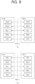
- FIG. 8 shows a radio protocol architecture for a SL communication, in accordance with an example of the present disclosure.
- the example of FIG. 8 may be combined with various embodiments and examples of the present disclosure. More specifically, FIG. 8(a) shows a user plane protocol stack, and FIG. 8(b) shows a control plane protocol stack.
- SLSS sidelink synchronization signal
- the SLSS may include a primary sidelink synchronization signal (PSSS) and a secondary sidelink synchronization signal (SSSS), as an SL-specific sequence.
- PSSS primary sidelink synchronization signal
- SSSS secondary sidelink synchronization signal
- the PSSS may be referred to as a sidelink primary synchronization signal (S-PSS)
- S-SSS sidelink secondary synchronization signal
- S-SSS sidelink secondary synchronization signal
- length-127 M-sequences may be used for the S-PSS
- length-127 gold sequences may be used for the S-SSS.
- a UE may use the S-PSS for initial signal detection and for synchronization acquisition.
- the UE may use the S-PSS and the S-SSS for acquisition of detailed synchronization and for detection of a synchronization signal ID.
- a physical sidelink broadcast channel may be a (broadcast) channel for transmitting default (system) information which must be first known by the UE before SL signal transmission/reception.
- the default information may be information related to SLSS, a duplex mode (DM), a time division duplex (TDD) uplink/downlink (UL/DL) configuration, information related to a resource pool, a type of an application related to the SLSS, a subframe offset, broadcast information, or the like.
- DM duplex mode
- TDD time division duplex
- UL/DL uplink/downlink
- a payload size of the PSBCH may be 56 bits including 24-bit CRC.
- the S-PSS, the S-SSS, and the PSBCH may be included in a block format (e.g., SL synchronization signal (SS)/PSBCH block, hereinafter, sidelinksynchronization signal block (S-SSB)) supporting periodical transmission.
- the S-SSB may have the same numerology (i.e., SCS and CP length) as a physical sidelink control channel (PSCCH)/physical sidelink shared channel (PSSCH) in a carrier, and a transmission bandwidth may exist within a (pre-)configured sidelink (SL) BWP.
- the S-SSB may have a bandwidth of 11 resource blocks (RBs).
- the PSBCH may exist across 11 RBs.
- a frequency position of the S-SSB may be (pre-)configured. Accordingly, the UE does not have to perform hypothesis detection at frequency to discover the S-SSB in the carrier.
- FIG. 9 shows a UE performing V2X or SL communication, in accordance with an embodiment of the present disclosure.
- the embodiment of FIG. 9 may be combined with various embodiments and examples of the present disclosure.
- the term 'UE' may generally imply a UE of a user.
- the BS may also be regarded as a sort of the UE.
- a UE 1 may be a first apparatus 100
- a UE 2 may be a second apparatus 200.
- the UE 1 may select a resource unit corresponding to a specific resource in a resource pool which implies a set of series of resources.
- the UE 1 may transmit an SL signal by using the resource unit.
- a resource pool in which the UE 1 is capable of transmitting a signal may be configured to the UE 2 which is a receiving UE, and the signal of the UE 1 may be detected in the resource pool.
- the BS may inform the UE 1 of the resource pool. Otherwise, if the UE 1 is out of the connectivity range of the BS, another UE may inform the UE 1 of the resource pool, or the UE 1 may use a pre-configured resource pool.
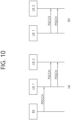
- FIG. 10(b) shows a UE operation related to an LTE transmission mode 2 or an LTE transmission mode 4.
- FIG. 10(b) shows a UE operation related to an NR resource allocation mode 2.
- a BS may schedule an SL resource to be used by the UE for SL transmission.
- the BS may perform resource scheduling to a UE 1 through a PDCCH (more specifically, downlink control information (DCI)), and the UE 1may perform V2X or SL communication with respect to a UE 2 according to the resource scheduling.
- the UE 1 may transmit a sidelink control information (SCI) to the UE 2 through a physical sidelink control channel (PSCCH), and thereafter transmit data based on the SCI to the UE 2 through a physical sidelink shared channel (PSSCH).
- SCI sidelink control information
- PSCCH physical sidelink control channel
- PSSCH physical sidelink shared channel
- the UE may determine an SL transmission resource within an SL resource configured by a BS/network or a pre-configured SL resource.
- the configured SL resource or the pre-configured SL resource may be a resource pool.
- the UE may autonomously select or schedule a resource for SL transmission.
- the UE may perform SL communication by autonomously selecting a resource within a configured resource pool.
- the UE may autonomously select a resource within a selective window by performing a sensing and resource (re)selection procedure.
- the sensing may be performed in unit of subchannels.
- the UE 1 which has autonomously selected the resource within the resource pool may transmit the SCI to the UE 2 through a PSCCH, and thereafter may transmit data based on the SCI to the UE 2 through a PSSCH.
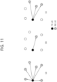
- FIG. 11 shows three cast types, in accordance with an example of the present disclosure.
- the example of FIG. 11 may be combined with various embodiments and examples of the present disclosure.
- FIG. 11(a) shows broadcast-type SL communication
- FIG. 11(b) shows unicast type-SL communication
- FIG. 11(c) shows groupcast-type SL communication.
- a UE may perform one-to-one communication with respect to another UE.
- the UE may perform SL communication with respect to one or more UEs in a group to which the UE belongs.
- SL groupcast communication may be replaced with SL multicast communication, SL one-to-many communication, or the like.
- a transmitting UE may be a UE transmitting data to a (target) receiving UE (RX UE).
- a TX UE may be a UE performing PSCCH and/or PSSCH transmission.
- a TX UE may be a UE that transmits an SL CSI-RS and/or SL CSI report request indicator to a (target) RX UE.
- a RX UE is a UE that transmits to a TX UE a SL (L1) RSRP measurement value measured based on a (pre-defined) reference signal and/or the SL (L1) RSRP report request indicator received from the TX UE.
- a RX UE may be a UE that transmits its own data to a TX UE.
- a RX UE may be a UE that performs SL RLM and/or SL RLF operations based on a reference signal on a (control) channel and/or a (pre-configured) (control) channel received from a TX UE.
- the RX UE when the RX UE transmits SL HARQ feedback information for the PSSCH and/or PSCCH received from the TX UE, the following scheme or some of the following schemes may be considered.
- the following scheme or some of the following schemes may be limitedly applied only when the RX UE successfully decodes/detects the PSCCH scheduling the PSSCH.
- the transmitting UE may transmit the entirety or part of information described below to the receiving UE through the SCI.
- the transmitting UE may transmit the entirety or part of the information described below to the receiving UE through the first SCI and/or the second SCI.
- the PSCCH may be replaced/substituted with at least one of SCI, first SCI, and/or second SCI.
- the SCI may be replaced/replaced by the PSCCH, the first SCI and/or the second SCI.
- the PSSCH may be replaced/substituted with the second SCI.
- the first SCI including the first SCI configuration field group may be referred to as 1st SCI
- the second SCI including the second SCI configuration field group may be referred to as 2nd SCI.
- the 1st SCI may be transmitted to the receiving UE through the PSCCH.
- the 2nd SCI may be transmitted to the receiving UE through (independent) PSCCH, or may be piggybacked with data through PSSCH and transmitted.
- configuration may mean (resource pool specific) (pre-) configuration from a base station or network (via pre-defined signaling (e.g., SIB, MAC, RRC, etc.)).
- pre-defined signaling e.g., SIB, MAC, RRC, etc.
- RLF may be determined based on an OUT-OF-SYNCH (OOS) indicator or an IN-SYNCH (IS) indicator
- RLF may be replaced/replaced by an OUT-OF-SYNCH (OOS) or an IN-SYNCH (IS).
- a resource block may be replaced/substituted with a sub-carrier.
- a packet or traffic may be substituted/replaced with a transport block (TB) or MAC PDU according to a transmitted layer.
- a CBG may be replaced/substituted with a TB.
- a source ID may be replaced/substituted with a destination ID.
- a L1 ID may be replaced/substituted by a L2 ID.
- a L1 ID may be a L1 source ID or a L1 destination ID.
- a L2 ID may be a L2 source ID or a L2 destination ID.
- a channel may be replaced/substituted with a signal.
- transmission/reception of a channel may include transmission/reception of a signal.
- transmission/reception of a signal may include transmission/reception of a channel.
- a cast type may be interchanged/substituted with a unicast, a groupcast, and/or a broadcast.
- a cast type may be interchanged/substituted with at least one of unicast, groupcast, and/or broadcast.
- the cast or cast type may include unicast, groupcast and/or broadcast.
- resources may be interchanged/replaced with slots or symbols.
- a (physical) channel used when the RX UE transmits at least one of the following information to the TX UE may be referred to as a PSFCH.
- the sidelink information may include at least one of a sidelink message, a sidelink packet, a sidelink service, sidelink data, sidelink control information in accordance with the present invention, and/or a sidelink transport block (TB).
- the sidelink information may be transmitted through a PSSCH and/or a PSCCH.
- the UE may perform RSRP measurement by using reference signals transmitted through a plurality of antenna ports.
- the UE may perform RSRP measurement using reference signals transmitted through a plurality of antenna ports on a pre-defined channel.
- RSRP measurement may include L1 RSRP measurement.
- the UE may perform RSRP measurement using reference signals (RSs) transmitted through a plurality of antenna ports.
- RSs reference signals
- PSSCH DM-RS rank information and/or PSSCH DM-RS antenna port information may be signaled through 1st SCI (e.g., PSCCH).
- the receiving UE may perform RSRP measurement by using RSs transmitted through a plurality of antenna ports.
- Various embodiments and examples of the present disclosure propose a method for efficiently supporting RSRP measurement using reference signals transmitted through a plurality of antenna ports.
- the UE may consider the sum of the measured RSRP values as the final/representative RSRP measurement value. For example, according to the present invention, after the UE measures RSRP for all reference signals of different antenna port indexes, the UE may determine the sum of the measured RSRP values as the final/representative RSRP measurement value. In examples not belonging to the present invention, for example, after the UE measures RSRP for each RS of a pre-configured number (e.g., K) of AP indexes, the UE may determine the sum of the measured RSRP values as the final/representative RSRP measurement value.
- K pre-configured number
- the UE may determine the sum of the measured RSRP values as the final/representative RSRP measurement value. For example, after the UE measures RSRP for each RS of the pre-configured relatively low K AP indexes, the UE may determine the sum of the measured RSRP values as the final/representative RSRP measurement value.
- the relatively high AP index may be an AP index having an index value higher than a specific value.
- the relatively low AP index may be an AP index having an index value lower than a specific value.
- the UE may determine the maximum or minimum value among the measured RSRP values as the final/representative RSRP measurement value.
- the UE may determine the maximum or minimum value among the measured RSRP values as the final/representative RSRP measurement value.
- the UE may determine the maximum or minimum value among the measured RSRP values as the final/representative RSRP measurement value. For example, after the UE measures RSRP for each RS of a pre-configured relatively low K AP index, the UE may determine the maximum or minimum value among the measured RSRP values as the final/representative RSRP measurement value.
- the UE may determine an average value or a weighted average value of the measured RSRP values as the final/representative RSRP measurement value. For example, after the UE measures RSRP for each RS of a pre-configured number (e.g., K) of AP indexes, the UE may determine an average value or a weighted average value of the measured RSRP values as the final/representative RSRP measurement value.
- K pre-configured number
- the UE determines the average value or weighted average value of the measured RSRP values as the final/representative RSRP measurement value. For example, after the UE measures the RSRP for each RS of a pre-configured relatively low K AP indexes, the UE determines the average value or the weighted average value of the measured RSRP values as the final/representative RSRP measurement value.
- the RSRP measurement value for the RS of the corresponding antenna port index may be the final/representative value.
- the UE may measure the RSRP for the reference signal of the antenna port index where K is 1 among the two different antenna port indexes, and the UE may determine the final/representative RSRP value based on the measured RSRP value.
- the UE derives/determines the final/representative RSRP value by adding a pre-configured offset value.
- the pre-configured offset value may be determined based on the number of antenna ports used to transmit the reference signal.
- the pre-configured offset value may be determined based on a rank value related to the reference signal.
- the pre-configured offset value may be 10*log (the number of antennas used to transmit the reference signal).
- the pre-configured offset value may be 10*log 2 (the number of antennas used to transmit the reference signal).
- the pre-configured offset value may be 10*log (a rank value related to the reference signal).
- the pre-configured offset value may be 10*log 2 (a rank value related to the reference signal).
- the pre-configured offset value may be 10*log2.
- the pre-configured offset value may be configured/determined differently according to service type, priority, service requirement (e.g., priority, reliability, latency, minimum required communication range), cast type (e.g., unicast, groupcast, broadcast) and/or congestion level.
- service type e.g., priority, reliability, latency, minimum required communication range
- cast type e.g., unicast, groupcast, broadcast
- congestion level e.g., unicast, groupcast, broadcast
- FIG. 12 shows multiplexing cases of a PSCCH and a PSSCH related with the PSCCH, in accordance with an example of the present disclosure.
- the example of FIG. 12 may be combined with various embodiments and examples of the present disclosure.
- multiplexing cases of a PSCCH and a PSSCH related with the PSCCH may include option 1, option 2, and option 3.
- option 1 may include option 1A and option 1B.
- the meaning of "related" in the PSSCH related with the PSCCH may mean that the PSCCH transmits at least information necessary for decoding the PSSCH.
- option 1 may be that the PSCCH and the related PSSCH are transmitted using non-overlapping time resources.
- option 1A the frequency resources used by the PSCCH and the related PSSCH may be the same.
- option 1B frequency resources used by the PSCCH and the related PSSCH may be different.
- option 2 may be that the PSCCH and the related PSSCH may be transmitted using non-overlapping frequency resources in all time resources used for transmission.
- the time resource used by the two channels may be the same.
- option 3 the PSCCH and a part of the related PSSCH may be transmitted using overlapping time resources in non-overlapping frequency resources, and another part of the related PSSCH and/or another part of the PSCCH may be transmitted using non-overlapping time resources.
- information on whether or not frequency division multiplexing (FDM) between a reference signal and data and/or ratio information of energy per resource element (EPRE)/power spectral density (PSD) between a reference signal and data (e.g., data being performed FDM) on the same symbol may be provided by predefined signaling.
- the UE may receive information on whether FDM between a reference signal and data and/or information on a ratio of EPRE/PSD between a reference signal and data (e.g., data being performed FDM) through predefined signaling.
- the UE may receive information on whether FDM between a reference signal and data on the same symbol and/or information on a ratio of EPRE/PSD between a reference signal and data (e.g., data being performed FDM) on the same symbol through SCI or resource pool-specific configuration.
- the RSRP value may be compensated in consideration of specific information. For example, when the UE measures the RSRP for the reference signal, the UE may compensate the RSRP value based on a ratio occupied by the RE related to the reference signal among all REs in the same symbol or a ratio of power occupied by the RE related to the reference signal among the total symbol power in the same symbol.
- the UE may compensate the RSRP value based on 10*log(a ratio of the RE related to the reference signal among all REs in the same symbol) or 10*log(a ratio of power for the RE related to the reference signal among the total symbol power). For example, when the UE measures the RSRP for the reference signal, the UE may compensate the RSRP value based on 10*log 2 (a ratio of the RE related to the reference signal among all REs in the same symbol) or 10*log 2 (a ratio of power for the RE related to the reference signal among the total symbol power).
- the UE may not use the DM-RS on the PSSCH area being performed FDM with the PSCCH for RSRP measurement.
- PSCCH PSD/EPRE boosting is performed, the UE may not use the DM-RS on the PSSCH area being performed FDM with the PSCCH for RSRP measurement.
- the UE may use the PSCCH and the DM-RS on the PSSCH area being performed FDM for RSRP measurement, and the UE may compensate for the power value borrowed due to PSD/EPRE boosting of the PSCCH. That is, for example, the UE compensates for the power value borrowed due to PSD/EPRE boosting of the PSCCH being performed FDM, and the UE may average the RSRP measurement value for the DM-RS on the PSSCH area being performed FDM and the DM-RS on the PSSCH area being not performed FDM.
- the UE may use the PSCCH and the DM-RS on the PSSCH area being performed FDM for RSRP measurement, and the UE may compensate for a pre-configured offset value. That is, for example, the UE compensates the pre-configured offset value for the RSRP measurement value, and the UE may average the RSRP measurement value for the DM-RS on the PSSCH area being performed FDM and the DM-RS on the PSSCH area being not performed FDM.
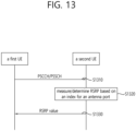
- FIG. 13 shows a procedure for a UE to determine RSRP based on an index of an antenna port, in accordance with an embodiment of the present disclosure.
- the embodiment of FIG. 13 may be combined with various embodiments and examples of the present disclosure.
- a first UE may transmit a reference signal on a PSCCH/PSSCH to a second UE.
- a reference signal may be a DM-RS or a sidelink CSI-RS.
- the first UE may transmit a DM-RS on a PSCCH/PSSCH to the second UE.
- the first UE may transmit a DM-RS on a PSCCH/PSSCH to the second UE using at least one antenna port.
- the second UE may measure/determine RSRP based on an index for an antenna port.
- the second UE may measure RSRP for each reference signal corresponding to an index for a different antenna port.
- the second UE may measure RSRP for each of reference signals corresponding to indices for pre-configured K antenna ports.
- the second UE may measure RSRP for each of the reference signals corresponding to a pre-configured K antenna ports having a relatively low index.
- the second UE may measure RSRP for each of the reference signals corresponding to a pre-configured K antenna ports having a relatively high index.
- the second UE may determine the sum of the measured RSRP values as the final/representative RSRP measurement value. In an example not belonging to the present invention, the second UE may determine the highest RSRP value among the measured RSRP values as the final/representative RSRP measurement value. In an example not belonging to the present invention, the second UE may determine the lowest RSRP value among the measured RSRP values as the final/representative RSRP measurement value.
- the second UE may measure RSRP for the reference signal of the antenna port index in which K is 1 among the two different antenna port indexes, and the second UE may determine the final/representative RSRP value based on the measured RSRP value.
- the second UE may derive/determine a final/representative RSRP value by adding a pre-configured first offset value to the measured RSRP value. For example, after the second UE measures the RSRP value for the reference signal of the pre-configured highest antenna port index, the second UE may derive/determine a final/representative RSRP value by adding a pre-configured first offset value to the measured RSRP value.
- the second UE may derive/determine a final/representative RSRP value by adding a pre-configured first offset value to the measured RSRP value.
- the pre-configured first offset value may be determined based on the number of antenna ports used for transmitting the reference signal.
- the pre-configured first offset value may be determined based on a rank value related to the reference signal.
- the pre-configured first offset value may be 10*log(the number of antennas used to transmit the reference signal).
- the pre-configured first offset value may be 10*log 2 (the number of antennas used to transmit the reference signal).
- the pre-configured first offset value may be 10*log2.
- the pre-configured first offset value may be configured/determined differently according to service type, priority, service requirement (e.g., priority, reliability, latency, minimum required communication range), cast type (e.g., unicast, groupcast, broadcast) and/or congestion level.
- the second UE may transmit the RSRP value to the first UE.
- the RSRP value may be a final/representative RSRP measurement value determined based on the index for the antenna port.
- the RSRP value may be a final/representative RSRP measurement value obtained by adding a pre-configured first offset value to the measured RSRP value.
- FIG. 14 shows a procedure for a UE to determine RSRP based on information related to FDM in accordance with an embodiment of the present disclosure.
- the embodiment of FIG. 14 may be combined with various embodiments and examples of the present disclosure.
- a first UE may transmit a reference signal on a PSCCH/PSSCH to a second UE.
- a reference signal may be a DM-RS or a sidelink CSI-RS.
- the first UE may transmit a DM-RS on a PSCCH/PSSCH to the second UE.
- the second UE measures/determines RSRP based on information related to FDM.
- the information related to the FDM includes information on whether or not frequency division multiplexing (FDM) between a reference signal and data and/or ratio information of energy per resource element (EPRE)/power spectral density (PSD) between a reference signal and data (e.g., data being performed FDM) on the same symbol.
- FDM frequency division multiplexing
- EPRE energy per resource element
- PSD power spectral density
- the information related to the FDM may be provided to the second UE by predefined signaling.
- the information related to the FDM may be provided to the second UE through a SCI or resource pool-specific configuration.
- the second UE may measure the RSRP for the reference signal on the PSCCH/PSSCH. For example, the second UE may compensate the measured RSRP value based on a ratio occupied by at least one RE related to the reference signal among all REs in the same symbol or a ratio of power occupied by at least one RE related to the reference signal among the total symbol power in the same symbol. For example, the second UE may compensate the RSRP value based on 10*log(a ratio of at least one RE related to the reference signal among all REs in the same symbol) or 10*log(a ratio of power for at least one RE related to the reference signal among the total symbol power).
- the second UE may compensate the RSRP value based on 10*log 2 (a ratio of at least one RE related to the reference signal among all REs in the same symbol) or 10*log 2 (a ratio of power for at least one RE related to the reference signal among the total symbol power).
- the second UE may not use the DM-RS on the PSSCH area being performed FDM with the PSCCH for RSRP measurement.
- PSCCH PSD/EPRE boosting is performed, the second UE may not use the DM-RS on the PSSCH area being performed FDM with the PSCCH for RSRP measurement.
- the second UE may use the PSCCH and the DM-RS on the PSSCH area being performed FDM for RSRP measurement, and the second UE may compensate for the power value borrowed due to PSD/EPRE boosting of the PSCCH.
- the second UE compensates for the power value borrowed due to PSD/EPRE boosting of the PSCCH being performed FDM, and the second UE may average the RSRP measurement value for the DM-RS on the PSSCH area being performed FDM and the DM-RS on the PSSCH area being not performed FDM.
- the second UE may determine the RSRP value by adding a pre-configured second offset value to the measured RSRP value, so that the UE averages the RSRP measurement value for the DM-RS on the PSSCH area being performed FDM and the DM-RS on the PSSCH area being not performed FDM.
- the second UE may transmit the RSRP value to the first UE.
- the RSRP value may be an RSRP measurement value compensated based on a ratio occupied by at least one RE related to a reference signal among all REs or a ratio of power occupied by at least one RE related to a reference signal among total symbol power.
- the RSRP value may be an RSRP measurement value in which a power value borrowed due to PSD/EPRE boosting of the PSCCH is compensated.
- the RSRP value may be a value obtained by adding a pre-configured second offset value to the measured RSRP value.
- FIG. 15 shows a procedure for compensating for a first offset value and a second offset value to a RSRP value measured by a UE in accordance with an embodiment of the present disclosure.
- the embodiment of FIG. 15 may be combined with various embodiments and examples of the present disclosure.
- a first UE transmits a reference signal on PSCCH/PSSCH using at least one antenna port, and that the reference signal and data are performed FDM.
- a first UE transmits a reference signal on a PSCCH/PSSCH to a second UE.
- a reference signal is a DM-RS or a sidelink CSI-RS.
- the first UE transmits a DM-RS on a PSCCH/PSSCH to the second UE.
- the first UE transmits a DM-RS on a PSCCH/PSSCH to the second UE using at least one antenna port.
- the second UE measures RSRP.
- the second UE may measure RSRP for each reference signal corresponding to an index for a different antenna port.
- the second UE may measure RSRP for each of reference signals corresponding to indices for pre-configured K antenna ports.
- the second UE may measure RSRP for each of the reference signals corresponding to a pre-configured K antenna ports having a relatively high index.
- the second UE may measure a RSRP value for the reference signal of one pre-configured antenna port index.
- the second terminal may not use a reference signal on the PSSCH area being performed FDM with the PSCCH for RSRP measurement. That is, for example, when the PSCCH/PSSCH multiplexing of the option 3 described above is used for a reference signal transmitted using at least one antenna port, the second UE may measure RSRP for a reference signal corresponding to an index for one pre-configured antenna port, and a reference signal on the PSSCH area being performed FDM with the PSCCH may not be used for RSRP measurement.
- the second UE compensates a first offset value to the measured RSRP value.
- the first offset value is the above-described pre-configured first offset value.
- the second UE may add the first offset value determined based on the number of antenna ports used to transmit the reference signal to the measured RSRP value.
- the second UE may add the first offset value determined based on a rank value related to the reference signal to the measured RSRP value.
- the second UE may add a value of 10*log(the number of antennas used to transmit the reference signal) to the measured RSRP value.
- the second UE may add a value of 10*log 2 (the number of antennas used to transmit the reference signal) to the measured RSRP value.
- the second UE compensates a second offset value to the measured RSRP value.
- the second offset value may be the pre-configured second offset value.
- the second offset value may be determined based on a ratio occupied by at least one RE related to the reference signal among all REs in the same symbol or a ratio of power occupied by at least one RE related to the reference signal among total symbol power.
- the second offset value may be determined based on 10*log(a ratio occupied by at least one RE related to the reference signal among all REs in the same symbol) or 10*log (a ratio of power occupied by at least one RE related to the reference signal among total symbol power in the same symbol).
- the second offset value may be determined based on 10*log 2 (a ratio occupied by at least one RE related to the reference signal among all REs in the same symbol) or 10*log 2 (a ratio of power occupied by at least one RE related to the reference signal among total symbol power in the same symbol).
- the second offset value may be determined based on a power value borrowed due to PSD/EPRE boosting of the PSCCH being performed FDM.
- the second UE may transmit the RSRP value to the first UE.
- the RSRP value may be a value obtained by adding a second offset value to the RSRP value measured by the second UE and, optionally, a first offset value.
- a SCI related to initial transmission may include resource allocation information may include scheduling/resource allocation information related to retransmission (e.g., the number/location of time domain resources, the number/location of frequency domain resources, MCS).
- resource allocation information may include scheduling/resource allocation information related to retransmission (e.g., the number/location of time domain resources, the number/location of frequency domain resources, MCS).
- a SCI related to retransmission may include scheduling/resource allocation information related to initial transmission.
- a sidelink CSI-RS is transmitted on initial transmission, it may need to be defined whether the sidelink CSI-RS should be transmitted also on the retransmission. For example, whether to transmit sidelink CSI-RS on retransmission may have to be defined whether it can be independently determined. For example, if the UE transmits a sidelink CSI-RS when performing initial transmission, whether the UE must transmit the sidelink CSI-RS even when performing retransmission may be defined. For example, when the UE performs retransmission, it may be defined whether or not to perform sidelink CSI-RS transmission can be independently determined.
- the UE may still determine scheduling/resource allocation information related to retransmission based on the successfully received SCI related to initial transmission.
- the UE cannot know whether the sidelink CSI-RS (e.g., the sidelink CSI-RS signaled through the retransmission-related SCI) is actually transmitted, the UE may ultimately fail to receive the packet.
- various embodiments of the present disclosure may be extended to solve the problem of whether sidelink CSI reporting and/or RSRP information should be included/piggybacked even on retransmission.
- various embodiments of the present disclosure may be extended to solve the problem of whether sidelink CSI-RS, sidelink CSI report and/or RSRP information should be included/piggybacked even on retransmission.
- a UE when a UE performs initial transmission related to a transport block (TB), if the UE has transmitted/piggybacked sidelink CSI-RS, sidelink CSI report and/or RSRP information (e.g., L1 RSRP information), it may be configured for the UE to include/piggyback sidelink CSI-RS, sidelink CSI report and/or RSRP information even on retransmission.
- RSRP information e.g., L1 RSRP information
- a UE when a UE performs initial transmission related to a specific TB, if the UE has transmitted/piggybacked sidelink CSI-RS, sidelink CSI report and/or RSRP information (e.g., L1 RSRP information), it may be configured for the UE to include/piggyback sidelink CSI-RS, sidelink CSI report and/or RSRP information even on some or all subsequent retransmissions.
- sidelink CSI report and/or RSRP information e.g., L1 RSRP information
- a UE when a UE performs initial transmission related to a specific TB, if the UE has transmitted/piggybacked sidelink CSI-RS, sidelink CSI report and/or RSRP information (e.g., L1 RSRP information), it may be configured for the UE not to include/piggyback sidelink CSI-RS, sidelink CSI report and/or RSRP information even on some or all subsequent retransmissions.
- RSRP information e.g., L1 RSRP information
- an embodiment of the present disclosure may be extended and applied to signaling to the UE information on whether to transmit sidelink CSI-RS on retransmission, through SCI related to initial transmission.
- a total of N times e.g., the number of times including all initial transmission/retransmission
- what number, rate, and/or time pattern, sidelink CSI-RS, sidelink CSI report and/or RSRP information transmission should be performed may be configured for the UE.
- the UE performs transmission related to a specific TB a total of N times with what number, rate, and/or time pattern, sidelink CSI-RS, sidelink CSI report and/or RSRP information transmission should be performed may be pre-configured resource poolspecifically for the UE.
- the UE when the UE performs TB-related transmission a total of 4 times, if a sidelink CSI-RS is transmitted on a first transmission, the UE may be configured to perform the sidelink CSI-RS transmission in a third transmission. For example, when the UE performs TB-related transmission a total of 4 times, if the sidelink CSI-RS is transmitted on a first transmission, the UE may omit the sidelink CSI-RS on a second/fourth transmission.
- transmission/piggyback of sidelink CSI-RS, sidelink CSI report and/or RSRP information on retransmission may be defined to be performed/determined independently of operation/form on initial transmission.
- the UE may perform transmission/piggyback of sidelink CSI-RS, sidelink CSI report and/or RSRP information on retransmission independently of operation/form of initial transmission.
- FIG. 16 shows a procedure for a UE to perform a plurality of TB-related transmissions in accordance with an embodiment of the present disclosure.
- the embodiment of FIG. 16 may be combined with various embodiments and examples of the present disclosure.
- the first UE when the first UE performs TB-related transmission a total of 4 times, if a sidelink CSI-RS is transmitted based on a first transmission, it may be assumed that the sidelink CSI-RS is configured to be transmitted based on a third transmission. For example, when the first UE performs TB-related transmission 4 times (e.g., the number of times including all initial transmission/retransmission), with what number, rate, and/or time pattern, the transmission of sidelink CSI-RS, sidelink CSI report and/or RSRP information should be performed may be configured for the first UE.
- TB-related transmission 4 times e.g., the number of times including all initial transmission/retransmission
- the transmission of sidelink CSI-RS, sidelink CSI report and/or RSRP information should be performed may be configured for the first UE.
- a first UE may transmit a sidelink CSI-RS to a second UE on a first transmission related with a TB.
- the first transmission related with the TB may be an initial transmission.
- the first UE may transmit/piggyback the sidelink CSI-RS, the sidelink CSI report and/or RSRP information (e.g., L1 RSRP information) on the first transmission related to the TB.
- RSRP information e.g., L1 RSRP information
- the first UE may perform a second transmission related to the TB to the second UE.
- the first UE may omit transmission/piggyback of sidelink CSI-RS, sidelink CSI report and/or RSRP information (e.g., L1 RSRP information) on the second transmission related to TB.
- the first UE may be configured to perform transmission of sidelink CSI-RS, sidelink CSI report and/or RSRP information (e.g., L1 RSRP information) though a third transmission related to TB through predefined signaling.
- the first UE may omit transmission/piggyback of sidelink CSI-RS, sidelink CSI report and/or RSRP information (e.g., L1 RSRP information) on the second transmission related to TB based on a predefined configuration.
- RSRP information e.g., L1 RSRP information
- the first UE may transmit the sidelink CSI-RS to the second UE on a third transmission related to the TB.
- the first UE may transmit/piggyback the sidelink CSI-RS, the sidelink CSI report and/or RSRP information (e.g., L1 RSRP information) on a fourth transmission related to the TB.
- the first UE may be configured to perform transmission of sidelink CSI-RS, sidelink CSI report and/or RSRP information on the third transmission related to TB through predefined signaling.
- the first UE may transmit/piggyback the sidelink CSI-RS, the sidelink CSI report and/or RSRP information (e.g., L1 RSRP information) on the third transmission related to the TB based on a predefined configuration.
- RSRP information e.g., L1 RSRP information
- the first UE may perform a fourth transmission related to the TB to the second UE.
- the first UE may omit transmission/piggyback of sidelink CSI-RS, sidelink CSI report and/or RSRP information (e.g., L1 RSRP information) on the fourth transmission related to TB.
- the first terminal may be configured to perform transmission of sidelink CSI-RS, sidelink CSI report and/or RSRP information on the third transmission related to TB through predefined signaling.
- the first UE may omit transmission/piggyback of sidelink CSI-RS, sidelink CSI report and/or RSRP information (e.g., L1 RSRP information) on the fourth transmission related to TB based on a predefined configuration.
- RSRP information e.g., L1 RSRP information
- the first UE may perform transmission/piggyback of sidelink CSI-RS, sidelink CSI report and/or RSRP information on retransmission independently of operation/form of initial transmission.
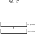
- FIG. 17 shows a method for a first device to determine RSRP based on indexes for a plurality of antenna ports in accordance with an embodiment of the present disclosure.
- the embodiment of FIG. 17 may be combined with various embodiments of the present disclosure.
- the first device 100 may receive a plurality of reference signals from a second device 200 through a physical sidelink control channel (PSCCH) or a physical sidelink shared channel (PSSCH).
- the plurality of reference signals may be transmitted through a plurality of antenna ports.
- the first device 100 may determine a reference signal received power (RSRP) value using the plurality of reference signals based on indexes for the plurality of antenna ports. For example, in accordance with the present invention, the first device 100 may measure RSRP using a reference signal of each of the indexes for the plurality of antenna ports. For example, in accordance with the present invention, the RSRP value may be determined as the sum of the RSRP measurement values of each of the indexes for the plurality of antenna ports. In examples not belonging to the present invention, for example, the RSRP value may be determined as an average value for the RSRP measurement value of each of the indexes for the plurality of antenna ports.
- RSRP reference signal received power
- the RSRP value may be determined as the largest value among the RSRP measurement values of each of the indexes for the plurality of antenna ports.
- the RSRP value may be determined as the smallest value among the RSRP measurement values of each of the indexes for the plurality of antenna ports.
- the first device 100 may measure RSRP through a reference signal of an index for a pre-configured antenna port.
- the RSRP value may be determined as a value obtained by adding a pre-configured offset value to the RSRP measurement value.
- the pre-configured offset value is determined based on the number of the plurality of antenna ports.
- the pre-configured offset value is determined differently based on at least one of a service type, a priority, a service requirement, or a cast type.
- information related to whether at least one reference signal among the plurality of reference signals is performed frequency division multiplexing (FDM) with sidelink data is transmitted through predefined signaling.
- information related to whether at least one reference signal among the plurality of reference signals is performed frequency division multiplexing (FDM) with sidelink data is transmitted to the first device 100 through predefined signaling.
- the first device 100 compensates a pre-configured value for the RSRP value. For example, based on the at least one reference signal being performed FDM with the sidelink data, the at least one reference signal may be not used for RSRP measurement.
- the first device 100 may transmit the RSRP value to the second device 200.
- the processor 102 of the first device 100 may control the transceiver 106 to receive a plurality of reference signals from a second device 200 through a physical sidelink control channel (PSCCH) or a physical sidelink shared channel (PSSCH). And, for example, the processor 102 of the first device 100 may determine a reference signal received power (RSRP) value using the plurality of reference signals based on indexes for the plurality of antenna ports. And, for example, the processor 102 of the first device 100 may control the transceiver 106 to transmit the RSRP value to the second device 200.
- RSRP reference signal received power
- a first device configured to perform wireless communication
- the first device may comprise: one or more memories storing instructions; one or more transceivers; and one or more processors connected to the one or more memories and the one or more transceivers.
- the one or more processors may execute the instructions to: receive a plurality of reference signals from a second device through a physical sidelink control channel (PSCCH) or a physical sidelink shared channel (PSSCH), the plurality of reference signals are transmitted through a plurality of antenna ports, and determine a reference signal received power (RSRP) value using the plurality of reference signals based on indexes for the plurality of antenna ports, and transmit the RSRP value to the second device.
- PSCCH physical sidelink control channel
- PSSCH physical sidelink shared channel
- an apparatus configured to control a first user equipment (UE) may be provided.
- the apparatus may comprise: one or more processors; and one or more memories operably connected to the one or more processors and storing instructions.
- the one or more processors may execute the instructions to: receive a plurality of reference signals from a second UE through a physical sidelink control channel (PSCCH) or a physical sidelink shared channel (PSSCH), the plurality of reference signals are transmitted through a plurality of antenna ports, and determine a reference signal received power (RSRP) value using the plurality of reference signals based on indexes for the plurality of antenna ports, and transmit the RSRP value to the second UE.
- PSCCH physical sidelink control channel
- PSSCH physical sidelink shared channel
- a non-transitory computer-readable storage medium storing instructions may be provided.
- the instructions when executed, cause a first device to: receive a plurality of reference signals from a second device through a physical sidelink control channel (PSCCH) or a physical sidelink shared channel (PSSCH), the plurality of reference signals are transmitted through a plurality of antenna ports, and determine a reference signal received power (RSRP) value using the plurality of reference signals based on indexes for the plurality of antenna ports, and transmit the RSRP value to the second device.
- PSCCH physical sidelink control channel
- PSSCH physical sidelink shared channel
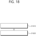
- FIG. 18 shows a method for a second device 200 to receive the RSRP value from a first device 100 in accordance with an example of the present disclosure.
- the example of FIG. 18 may be combined with various embodiments and examples of the present disclosure.
- the second device 200 may transmit a plurality of reference signals to the first device 100 through a physical sidelink control channel (PSCCH) or a physical sidelink shared channel (PSSCH).
- PSCCH physical sidelink control channel
- PSSCH physical sidelink shared channel
- the plurality of reference signals may be transmitted through a plurality of antenna ports.
- the second device 200 may receive a reference signal received power (RSRP) value from the first device 100.
- RSRP reference signal received power
- the RSRP value may be determined through the plurality of reference signals based on indexes for the plurality of antenna ports.
- the RSRP value may be determined as the sum of the RSRP measurement values of each of the indexes for the plurality of antenna ports.
- the RSRP value may be determined as an average value for the RSRP measurement value of each of the indexes for the plurality of antenna ports.
- the RSRP value may be determined as the largest value among the RSRP measurement values of each of the indexes for the plurality of antenna ports.
- the RSRP value may be determined as the smallest value among the RSRP measurement values of each of the indexes for the plurality of antenna ports.
- RSRP may be measured by the first device 100 through a reference signal of an index for a pre-configured antenna port.
- the RSRP value may be determined as a value obtained by adding a pre-configured offset value to the RSRP measurement value.
- the pre-configured offset value is determined based on the number of the plurality of antenna ports.
- the pre-configured offset value is determined differently based on at least one of a service type, a priority, a service requirement, or a cast type.
- information related to whether at least one reference signal among the plurality of reference signals is performed frequency division multiplexing (FDM) with sidelink data is transmitted through predefined signaling.
- information related to whether at least one reference signal among the plurality of reference signals is performed frequency division multiplexing (FDM) with sidelink data is transmitted to the first device 100 through predefined signaling.
- a pre-configured value may be compensated for the RSRP value by the first device 100.
- the at least one reference signal may be not used for RSRP measurement.
- the processor 202 of the second device 200 may control the transceiver 206 to transmit a plurality of reference signals to a first device 100 through a physical sidelink control channel (PSCCH) or a physical sidelink shared channel (PSSCH). And, the processor 202 of the second device 200 may control the transceiver 206 to receive a reference signal received power (RSRP) value from the first device 100.
- PSCCH physical sidelink control channel
- PSSCH physical sidelink shared channel
- RSRP reference signal received power
- a second device configured to perform wireless communication
- the second device may comprise: one or more memories storing instructions; one or more transceivers; and one or more processors connected to the one or more memories and the one or more transceivers.
- the one or more processors may execute the instructions to: transmit a plurality of reference signals to a first device through a physical sidelink control channel (PSCCH) or a physical sidelink shared channel (PSSCH) and receive a reference signal received power (RSRP) value from the first device.
- PSCCH physical sidelink control channel
- PSSCH physical sidelink shared channel
- RSRP reference signal received power
- the plurality of reference signals are transmitted through a plurality of antenna ports.
- the RSRP value is determined through the plurality of reference signals based on indexes for the plurality of antenna ports.
- FIG. 19 shows a communication system 1, in accordance with an example of the present disclosure.
- a communication system 1 to which various embodiments and examples of the present disclosure are applied includes wireless devices, Base Stations (BSs), and a network.
- the wireless devices represent devices performing communication using Radio Access Technology (RAT) (e.g., 5G New RAT (NR)) or Long-Term Evolution (LTE)) and may be referred to as communication/radio/5G devices.
- RAT Radio Access Technology
- the wireless devices may include, without being limited to, a robot 100a, vehicles 100b-1 and 100b-2, an extended Reality (XR) device 100c, a hand-held device 100d, a home appliance 100e, an Internet of Things (IoT) device 100f, and an Artificial Intelligence (AI) device/server 400.
- RAT Radio Access Technology
- NR 5G New RAT
- LTE Long-Term Evolution
- the wireless devices may include, without being limited to, a robot 100a, vehicles 100b-1 and 100b-2, an extended Reality (XR) device 100c, a hand-held device 100d, a home
- the vehicles may include a vehicle having a wireless communication function, an autonomous vehicle, and a vehicle capable of performing communication between vehicles.
- the vehicles may include an Unmanned Aerial Vehicle (UAV) (e.g., a drone).
- UAV Unmanned Aerial Vehicle
- the XR device may include an Augmented Reality (AR)/Virtual Reality (VR)/Mixed Reality (MR) device and may be implemented in the form of a Head-Mounted Device (HMD), a Head-Up Display (HUD) mounted in a vehicle, a television, a smartphone, a computer, a wearable device, a home appliance device, a digital signage, a vehicle, a robot, etc.
- the hand-held device may include a smartphone, a smartpad, a wearable device (e.g., a smartwatch or a smartglasses), and a computer (e.g., a notebook).
- the home appliance may include a TV, a refrigerator, and a washing machine.
- the IoT device may include a sensor and a smartmeter.
- the BSs and the network may be implemented as wireless devices and a specific wireless device 200a may operate as a BS/network node with respect to other wireless devices.
- the wireless devices 100a to 100f may be connected to the network 300 via the BSs 200.
- An AI technology may be applied to the wireless devices 100a to 100f and the wireless devices 100a to 100f may be connected to the AI server 400 via the network 300.
- the network 300 may be configured using a 3G network, a 4G (e.g., LTE) network, or a 5G (e.g., NR) network.
- the wireless devices 100a to 100f may communicate with each other through the BSs 200/network 300, the wireless devices 100a to 100f may perform direct communication (e.g., sidelink communication) with each other without passing through the BSs/network.
- the vehicles 100b-1 and 100b-2 may perform direct communication (e.g.
- V2V Vehicle-to-Vehicle
- V2X Vehicle-to-everything
- Wireless communication/connections 150a, 150b, or 150c may be established between the wireless devices 100a to 100f/BS 200, or BS 200/BS 200.
- the wireless communication/connections may be established through various RATs (e.g., 5G NR) such as uplink/downlink communication 150a, sidelink communication 150b (or, D2D communication), or inter BS communication(e.g. relay, Integrated Access Backhaul(IAB)).
- the wireless devices and the BSs/the wireless devices may transmit/receive radio signals to/from each other through the wireless communication/connections 150a and 150b.
- the wireless communication/connections 150a and 150b may transmit/receive signals through various physical channels.
- various configuration information configuring processes various signal processing processes (e.g., channel encoding/decoding, modulation/demodulation, and resource mapping/demapping), and resource allocating processes, for transmitting/receiving radio signals, may be performed based on the various proposals of the present disclosure.
- various signal processing processes e.g., channel encoding/decoding, modulation/demodulation, and resource mapping/demapping
- resource allocating processes for transmitting/receiving radio signals
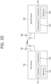
- FIG. 20 shows wireless devices, in accordance with an embodiment of the present disclosure.
- a first wireless device 100 and a second wireless device 200 may transmit radio signals through a variety of RATs (e.g., LTE and NR).
- ⁇ the first wireless device 100 and the second wireless device 200 ⁇ may correspond to ⁇ the wireless device 100x and the BS 200 ⁇ and/or ⁇ the wireless device 100x and the wireless device 100x ⁇ of FIG. 19 .
- the first wireless device 100 may include one or more processors 102 and one or more memories 104 and additionally further include one or more transceivers 106 and/or one or more antennas 108.
- the processor(s) 102 may control the memory(s) 104 and/or the transceiver(s) 106 and may be configured to implement the descriptions, functions, procedures, proposals, methods, and/or operational flowcharts disclosed in this document.
- the processor(s) 102 may process information within the memory(s) 104 to generate first information/signals and then transmit radio signals including the first information/signals through the transceiver(s) 106.
- the processor(s) 102 may receive radio signals including second information/signals through the transceiver 106 and then store information obtained by processing the second information/signals in the memory(s) 104.
- the memory(s) 104 may be connected to the processor(s) 102 and may store a variety of information related to operations of the processor(s) 102.
- the memory(s) 104 may store software code including commands for performing a part or the entirety of processes controlled by the processor(s) 102 or for performing the descriptions, functions, procedures, proposals, methods, and/or operational flowcharts disclosed in this document.
- the processor(s) 102 and the memory(s) 104 may be a part of a communication modem/circuit/chip designed to implement RAT (e.g., LTE or NR).
- the transceiver(s) 106 may be connected to the processor(s) 102 and transmit and/or receive radio signals through one or more antennas 108.
- Each of the transceiver(s) 106 may include a transmitter and/or a receiver.
- the transceiver(s) 106 may be interchangeably used with Radio Frequency (RF) unit(s).
- the wireless device may represent a communication modem/circuit/chip.
- the second wireless device 200 may include one or more processors 202 and one or more memories 204 and additionally further include one or more transceivers 206 and/or one or more antennas 208.
- the processor(s) 202 may control the memory(s) 204 and/or the transceiver(s) 206 and may be configured to implement the descriptions, functions, procedures, proposals, methods, and/or operational flowcharts disclosed in this document.
- the processor(s) 202 may process information within the memory(s) 204 to generate third information/signals and then transmit radio signals including the third information/signals through the transceiver(s) 206.
- the processor(s) 202 may receive radio signals including fourth information/signals through the transceiver(s) 106 and then store information obtained by processing the fourth information/signals in the memory(s) 204.
- the memory(s) 204 may be connected to the processor(s) 202 and may store a variety of information related to operations of the processor(s) 202.
- the memory(s) 204 may store software code including commands for performing a part or the entirety of processes controlled by the processor(s) 202 or for performing the descriptions, functions, procedures, proposals, methods, and/or operational flowcharts disclosed in this document.
- the processor(s) 202 and the memory(s) 204 may be a part of a communication modem/circuit/chip designed to implement RAT (e.g., LTE or NR).
- the transceiver(s) 206 may be connected to the processor(s) 202 and transmit and/or receive radio signals through one or more antennas 208.
- Each of the transceiver(s) 206 may include a transmitter and/or a receiver.
- the transceiver(s) 206 may be interchangeably used with RF unit(s).
- the wireless device may represent a communication modem/circuit/chip.
- One or more protocol layers may be implemented by, without being limited to, one or more processors 102 and 202.
- the one or more processors 102 and 202 may implement one or more layers (e.g., functional layers such as PHY, MAC, RLC, PDCP, RRC, and SDAP).
- the one or more processors 102 and 202 may generate one or more Protocol Data Units (PDUs) and/or one or more Service Data Unit (SDUs) according to the descriptions, functions, procedures, proposals, methods, and/or operational flowcharts disclosed in this document.
- PDUs Protocol Data Units
- SDUs Service Data Unit
- the one or more processors 102 and 202 may generate messages, control information, data, or information according to the descriptions, functions, procedures, proposals, methods, and/or operational flowcharts disclosed in this document.
- the one or more processors 102 and 202 may generate signals (e.g., baseband signals) including PDUs, SDUs, messages, control information, data, or information according to the descriptions, functions, procedures, proposals, methods, and/or operational flowcharts disclosed in this document and provide the generated signals to the one or more transceivers 106 and 206.
- the one or more processors 102 and 202 may receive the signals (e.g., baseband signals) from the one or more transceivers 106 and 206 and acquire the PDUs, SDUs, messages, control information, data, or information according to the descriptions, functions, procedures, proposals, methods, and/or operational flowcharts disclosed in this document.
- signals e.g., baseband signals
- the one or more processors 102 and 202 may be referred to as controllers, microcontrollers, microprocessors, or microcomputers.
- the one or more processors 102 and 202 may be implemented by hardware, firmware, software, or a combination thereof.
- ASICs Application Specific Integrated Circuits
- DSPs Digital Signal Processors
- DSPDs Digital Signal Processing Devices
- PLDs Programmable Logic Devices
- FPGAs Field Programmable Gate Arrays
- the descriptions, functions, procedures, proposals, methods, and/or operational flowcharts disclosed in this document may be implemented using firmware or software and the firmware or software may be configured to include the modules, procedures, or functions.
- Firmware or software configured to perform the descriptions, functions, procedures, proposals, methods, and/or operational flowcharts disclosed in this document may be included in the one or more processors 102 and 202 or stored in the one or more memories 104 and 204 so as to be driven by the one or more processors 102 and 202.
- the descriptions, functions, procedures, proposals, methods, and/or operational flowcharts disclosed in this document may be implemented using firmware or software in the form of code, commands, and/or a set of commands.
- the one or more memories 104 and 204 may be connected to the one or more processors 102 and 202 and store various types of data, signals, messages, information, programs, code, instructions, and/or commands.
- the one or more memories 104 and 204 may be configured by Read-Only Memories (ROMs), Random Access Memories (RAMs), Electrically Erasable Programmable Read-Only Memories (EPROMs), flash memories, hard drives, registers, cash memories, computer-readable storage media, and/or combinations thereof.
- the one or more memories 104 and 204 may be located at the interior and/or exterior of the one or more processors 102 and 202.
- the one or more memories 104 and 204 may be connected to the one or more processors 102 and 202 through various technologies such as wired or wireless connection.
- the one or more transceivers 106 and 206 may transmit user data, control information, and/or radio signals/channels, mentioned in the methods and/or operational flowcharts of this document, to one or more other devices.
- the one or more transceivers 106 and 206 may receive user data, control information, and/or radio signals/channels, mentioned in the descriptions, functions, procedures, proposals, methods, and/or operational flowcharts disclosed in this document, from one or more other devices.
- the one or more transceivers 106 and 206 may be connected to the one or more processors 102 and 202 and transmit and receive radio signals.
- the one or more processors 102 and 202 may perform control so that the one or more transceivers 106 and 206 may transmit user data, control information, or radio signals to one or more other devices.
- the one or more processors 102 and 202 may perform control so that the one or more transceivers 106 and 206 may receive user data, control information, or radio signals from one or more other devices.
- the one or more transceivers 106 and 206 may be connected to the one or more antennas 108 and 208 and the one or more transceivers 106 and 206 may be configured to transmit and receive user data, control information, and/or radio signals/channels, mentioned in the descriptions, functions, procedures, proposals, methods, and/or operational flowcharts disclosed in this document, through the one or more antennas 108 and 208.
- the one or more antennas may be a plurality of physical antennas or a plurality of logical antennas (e.g., antenna ports).
- the one or more transceivers 106 and 206 may convert received radio signals/channels etc.
- the one or more transceivers 106 and 206 may convert the user data, control information, radio signals/channels, etc. processed using the one or more processors 102 and 202 from the base band signals into the RF band signals.
- the one or more transceivers 106 and 206 may include (analog) oscillators and/or filters.
- FIG. 21 shows a signal process circuit for a transmission signal, in accordance with an embodiment of the present disclosure.
- a signal processing circuit 1000 may include scramblers 1010, modulators 1020, a layer mapper 1030, a precoder 1040, resource mappers 1050, and signal generators 1060.
- An operation/function of FIG. 21 may be performed, without being limited to, the processors 102 and 202 and/or the transceivers 106 and 206 of FIG. 20 .
- Hardware elements of FIG. 21 may be implemented by the processors 102 and 202 and/or the transceivers 106 and 206 of FIG. 20 .
- blocks 1010 to 1060 may be implemented by the processors 102 and 202 of FIG. 20 .
- the blocks 1010 to 1050 may be implemented by the processors 102 and 202 of FIG. 20 and the block 1060 may be implemented by the transceivers 106 and 206 of FIG. 20 .
- Codewords may be converted into radio signals via the signal processing circuit 1000 of FIG. 21 .
- the codewords are encoded bit sequences of information blocks.
- the information blocks may include transport blocks (e.g., a UL-SCH transport block, a DL-SCH transport block).
- the radio signals may be transmitted through various physical channels (e.g., a PUSCH and a PDSCH).
- the codewords may be converted into scrambled bit sequences by the scramblers 1010.
- Scramble sequences used for scrambling may be generated based on an initialization value, and the initialization value may include ID information of a wireless device.
- the scrambled bit sequences may be modulated to modulation symbol sequences by the modulators 1020.
- a modulation scheme may include pi/2-Binary Phase Shift Keying (pi/2-BPSK), m-Phase Shift Keying (m-PSK), and m-Quadrature Amplitude Modulation (m-QAM).
- Complex modulation symbol sequences may be mapped to one or more transport layers by the layer mapper 1030.
- Modulation symbols of each transport layer may be mapped (precoded) to corresponding antenna port(s) by the precoder 1040.
- Outputs z of the precoder 1040 may be obtained by multiplying outputs y of the layer mapper 1030 by an N*M precoding matrix W.
- N is the number of antenna ports and M is the number of transport layers.
- the precoder 1040 may perform precoding after performing transform precoding (e.g., DFT) for complex modulation symbols. Alternatively, the precoder 1040 may perform precoding without performing transform precoding.
- transform precoding e.g., DFT
- the resource mappers 1050 may map modulation symbols of each antenna port to time-frequency resources.
- the time-frequency resources may include a plurality of symbols (e.g., a CP-OFDMA symbols and DFT-s-OFDMA symbols) in the time domain and a plurality of subcarriers in the frequency domain.
- the signal generators 1060 may generate radio signals from the mapped modulation symbols and the generated radio signals may be transmitted to other devices through each antenna.
- the signal generators 1060 may include Inverse Fast Fourier Transform (IFFT) modules, Cyclic Prefix (CP) inserters, Digitalto-Analog Converters (DACs), and frequency up-converters.
- IFFT Inverse Fast Fourier Transform
- CP Cyclic Prefix
- DACs Digitalto-Analog Converters
- Signal processing procedures for a signal received in the wireless device may be configured in a reverse manner of the signal processing procedures 1010 to 1060 of FIG. 21 .
- the wireless devices e.g., 100 and 200 of FIG. 20
- the received radio signals may be converted into baseband signals through signal restorers.
- the signal restorers may include frequency downlink converters, Analog-to-Digital Converters (ADCs), CP remover, and Fast Fourier Transform (FFT) modules.
- ADCs Analog-to-Digital Converters
- FFT Fast Fourier Transform
- the baseband signals may be restored to codewords through a resource demapping procedure, a postcoding procedure, a demodulation processor, and a descrambling procedure.
- a signal processing circuit for a reception signal may include signal restorers, resource demappers, a postcoder, demodulators, descramblers, and decoders.
- FIG. 22 shows another example of a wireless device, in accordance with an embodiment of the present disclosure.
- the wireless device may be implemented in various forms according to a use-case/service (refer to FIG. 19 ).
- wireless devices 100 and 200 may correspond to the wireless devices 100 and 200 of FIG. 20 and may be configured by various elements, components, units/portions, and/or modules.
- each of the wireless devices 100 and 200 may include a communication unit 110, a control unit 120, a memory unit 130, and additional components 140.
- the communication unit may include a communication circuit 112 and transceiver(s) 114.
- the communication circuit 112 may include the one or more processors 102 and 202 and/or the one or more memories 104 and 204 of FIG. 20 .
- the transceiver(s) 114 may include the one or more transceivers 106 and 206 and/or the one or more antennas 108 and 208 of FIG. 20 .
- the control unit 120 is electrically connected to the communication unit 110, the memory 130, and the additional components 140 and controls overall operation of the wireless devices. For example, the control unit 120 may control an electric/mechanical operation of the wireless device based on programs/code/commands/information stored in the memory unit 130.
- the control unit 120 may transmit the information stored in the memory unit 130 to the exterior (e.g., other communication devices) via the communication unit 110 through a wireless/wired interface or store, in the memory unit 130, information received through the wireless/wired interface from the exterior (e.g., other communication devices) via the communication unit 110.
- the additional components 140 may be variously configured according to types of wireless devices.
- the additional components 140 may include at least one of a power unit/battery, input/output (I/O) unit, a driving unit, and a computing unit.
- the wireless device may be implemented in the form of, without being limited to, the robot (100a of FIG. 19 ), the vehicles (100b-1 and 100b-2 of FIG. 19 ), the XR device (100c of FIG. 19 ), the hand-held device (100d of FIG. 19 ), the home appliance (100e of FIG. 19 ), the IoT device (100f of FIG.
- the wireless device may be used in a mobile or fixed place according to a use-example/service.
- the entirety of the various elements, components, units/portions, and/or modules in the wireless devices 100 and 200 may be connected to each other through a wired interface or at least a part thereof may be wirelessly connected through the communication unit 110.
- the control unit 120 and the communication unit 110 may be connected by wire and the control unit 120 and first units (e.g., 130 and 140) may be wirelessly connected through the communication unit 110.
- Each element, component, unit/portion, and/or module within the wireless devices 100 and 200 may further include one or more elements.
- the control unit 120 may be configured by a set of one or more processors.
- control unit 120 may be configured by a set of a communication control processor, an application processor, an Electronic Control Unit (ECU), a graphical processing unit, and a memory control processor.
- memory 130 may be configured by a Random Access Memory (RAM), a Dynamic RAM (DRAM), a Read Only Memory (ROM)), a flash memory, a volatile memory, a non-volatile memory, and/or a combination thereof.
- RAM Random Access Memory
- DRAM Dynamic RAM
- ROM Read Only Memory
- flash memory a volatile memory
- non-volatile memory and/or a combination thereof.
- FIG. 22 An example of implementing FIG. 22 will be described in detail with reference to the drawings.
- FIG. 23 shows a hand-held device, in accordance with an embodiment of the present disclosure.
- the hand-held device may include a smartphone, a smartpad, a wearable device (e.g., a smartwatch or a smartglasses), or a portable computer (e.g., a notebook).
- the hand-held device may be referred to as a mobile station (MS), a user terminal (UT), a Mobile Subscriber Station (MSS), a Subscriber Station (SS), an Advanced Mobile Station (AMS), or a Wireless Terminal (WT).
- MS mobile station
- UT user terminal
- MSS Mobile Subscriber Station
- SS Subscriber Station
- AMS Advanced Mobile Station
- WT Wireless Terminal
- a hand-held device 100 may include an antenna unit 108, a communication unit 110, a control unit 120, a memory unit 130, a power supply unit 140a, an interface unit 140b, and an I/O unit 140c.
- the antenna unit 108 may be configured as a part of the communication unit 110.
- Blocks 110 to 130/140a to140c correspond to the blocks 110 to 130/140 of FIG. 22 , respectively.
- the communication unit 110 may transmit and receive signals (e.g., data and control signals) to and from other wireless devices or BSs.
- the control unit 120 may perform various operations by controlling constituent elements of the hand-held device 100.
- the control unit 120 may include an Application Processor (AP).
- the memory unit 130 may store data/parameters/programs/code/commands needed to drive the hand-held device 100.
- the memory unit 130 may store input/output data/information.
- the power supply unit 140a may supply power to the hand-held device 100 and include a wired/wireless charging circuit, a battery, etc.
- the interface unit 140b may support connection of the hand-held device 100 to other external devices.
- the interface unit 140b may include various ports (e.g., an audio I/O port and a video I/O port) for connection with external devices.
- the I/O unit 140c may input or output video information/signals, audio information/signals, data, and/or information input by a user.
- the I/O unit 140c may include a camera, a microphone, a user input unit, a display unit 140d, a speaker, and/or a haptic module.
- the I/O unit 140c may acquire information/signals (e.g., touch, text, voice, images, or video) input by a user and the acquired information/signals may be stored in the memory unit 130.
- the communication unit 110 may convert the information/signals stored in the memory into radio signals and transmit the converted radio signals to other wireless devices directly or to a BS.
- the communication unit 110 may receive radio signals from other wireless devices or the BS and then restore the received radio signals into original information/signals.
- the restored information/signals may be stored in the memory unit 130 and may be output as various types (e.g., text, voice, images, video, or haptic) through the I/O unit 140c.
- FIG. 24 shows a vehicle or an autonomous vehicle, in accordance with an embodiment of the present disclosure.
- the vehicle or autonomous vehicle may be implemented by a mobile robot, a car, a train, a manned/unmanned Aerial Vehicle (AV), a ship, etc.
- AV Aerial Vehicle
- a vehicle or autonomous vehicle 100 may include an antenna unit 108, a communication unit 110, a control unit 120, a driving unit 140a, a power supply unit 140b, a sensor unit 140c, and an autonomous driving unit 140d.
- the antenna unit 108 may be configured as a part of the communication unit 110.
- the blocks 110/130/140a to 140d correspond to the blocks 110/130/140 of FIG. 22 , respectively.
- the communication unit 110 may transmit and receive signals (e.g., data and control signals) to and from external devices such as other vehicles, BSs (e.g., gNBs and road side units), and servers.
- the control unit 120 may perform various operations by controlling elements of the vehicle or the autonomous vehicle 100.
- the control unit 120 may include an Electronic Control Unit (ECU).
- the driving unit 140a may cause the vehicle or the autonomous vehicle 100 to drive on a road.
- the driving unit 140a may include an engine, a motor, a powertrain, a wheel, a brake, a steering device, etc.
- the power supply unit 140b may supply power to the vehicle or the autonomous vehicle 100 and include a wired/wireless charging circuit, a battery, etc.
- the sensor unit 140c may acquire a vehicle state, ambient environment information, user information, etc.
- the sensor unit 140c may include an Inertial Measurement Unit (IMU) sensor, a collision sensor, a wheel sensor, a speed sensor, a slope sensor, a weight sensor, a heading sensor, a position module, a vehicle forward/backward sensor, a battery sensor, a fuel sensor, a tire sensor, a steering sensor, a temperature sensor, a humidity sensor, an ultrasonic sensor, an illumination sensor, a pedal position sensor, etc.
- IMU Inertial Measurement Unit
- the autonomous driving unit 140d may implement technology for maintaining a lane on which a vehicle is driving, technology for automatically adjusting speed, such as adaptive cruise control, technology for autonomously driving along a determined path, technology for driving by automatically setting a path if a destination is set, and the like.
- the communication unit 110 may receive map data, traffic information data, etc. from an external server.
- the autonomous driving unit 140d may generate an autonomous driving path and a driving plan from the obtained data.
- the control unit 120 may control the driving unit 140a such that the vehicle or the autonomous vehicle 100 may move along the autonomous driving path according to the driving plan (e.g., speed/direction control).
- the communication unit 110 may aperiodically/periodically acquire recent traffic information data from the external server and acquire surrounding traffic information data from neighboring vehicles.
- the sensor unit 140c may obtain a vehicle state and/or surrounding environment information.
- the autonomous driving unit 140d may update the autonomous driving path and the driving plan based on the newly obtained data/information.
- the communication unit 110 may transfer information about a vehicle position, the autonomous driving path, and/or the driving plan to the external server.
- the external server may predict traffic information data using AI technology, etc., based on the information collected from vehicles or autonomous vehicles and provide the predicted traffic information data to the vehicles or the autonomous vehicles.
Landscapes
- Engineering & Computer Science (AREA)
- Signal Processing (AREA)
- Computer Networks & Wireless Communication (AREA)
- Quality & Reliability (AREA)
- Physics & Mathematics (AREA)
- Electromagnetism (AREA)
- Mobile Radio Communication Systems (AREA)
Claims (10)
- Procédé d'établissement de communication sans fil par un premier dispositif, le procédé comprenant:la réception (S1510), en provenance d'un deuxième dispositif par l'intermédiaire d'un canal physique de commande de liaison latérale, PSCCH, d'informations de commande de liaison latérale, SCI, pour programmer un canal physique de liaison latérale partagé, PSSCH;la réception, en provenance du deuxième dispositif par l'intermédiaire de blocs de ressources pour le PSSCH, d'une pluralité de signaux de référence de démodulation, DM-RS,dans lequel la pluralité de DM-RS est reçue par une pluralité de ports d'antenne;la détermination (S1520) d'une valeur de puissance de réception du signal de référence, RSRP, pour le PSSCH sur la base de la pluralité de DM-RS;la compensation (S1530) d'une première valeur de décalage pour la valeur RSRP en fonction d'au moins un multiplexage par répartition en fréquence, FDM, de DM-RS avec des données de liaison latérale,dans lequel la première valeur de décalage est une valeur configurée; etla compensation (S1540) d'une deuxième valeur de décalage pour la valeur RSRP,dans lequel la valeur RSRP est déterminée comme la somme de plusieurs valeurs de mesure RSRP,dans lequel les valeurs de mesure RSRP de la pluralité de valeurs de mesure RSRP sont des valeurs RSRP mesurées pour chacun de la pluralité de ports d'antenne, etdans lequel les informations relative au fait que l'au moins un DM-RS parmi la pluralité de DM-RS effectue une FDM avec les données de liaison latérale est transmis par le biais d'une signalisation prédéfinie.
- Procédé selon la revendication 1, comprenant en outre:la transmission (S1550) de la valeur RSRP au deuxième dispositif,dans lequel les SCI comprennent des informations sur le port d'antenne relatives à la pluralité de DM-RS pour le PSSCH.
- Procédé selon la revendication 1, comprenant en outre:
la détermination d'une perte de chemin de liaison latérale sur la base de la valeur RSRP. - Procédé selon la revendication 1, dans lequel la deuxième valeur de décalage est déterminée sur la base d'un rapport entre les RE occupés par l'au moins un DM-RS et tous les éléments de ressources, RE, d'un symbole.
- Procédé selon la revendication 1, dans lequel la deuxième valeur de décalage est déterminée sur la base d'un rapport entre la puissance occupée par les RE liés à l'au moins un DM-RS parmi les puissances pour tous les symboles liés à l'au moins un DM-RS.
- Procédé selon la revendication 1, dans lequel l'au moins un DM-RS est omis de la mesure RSRP, étant donné que l'au moins un DM-RS effectue la FDM avec les données de liaison latérale.
- Procédé selon la revendication 6, dans lequel l'augmentation liée à une énergie par élément de ressource, EPRE, pour le PSSCH ou l'augmentation liée à une densité spectrale de puissance, PSD, pour le PSSCH est réalisée.
- Procédé selon la revendication 1, dans lequel les SCI comprennent des informations relatives au fait qu'au moins un DM-RS parmi la pluralité de DM-RS a effectué une FDM avec les données de liaison latérale.
- Procédé selon la revendication 8, dans lequel les SCI comprennent au moins l'une des informations suivantes relatives à un EPRE entre l'au moins un DM-RS et les données de liaison latérale ou des informations relatives à un PSD entre l'au moins un DM-RS et les données de liaison latérale.
- Premier dispositif permettant d'établir une communication sans fil, le premier dispositif (100) comprenant:une ou plusieurs mémoires (104) stockant des instructions;un ou plusieurs émetteurs-récepteurs (106); etun ou plusieurs processeurs (102) connectés à la ou les mémoires et au(x) émetteur(s)-récepteur(s), dans lequel le ou les processeurs exécutent les instructions pour:recevoir, en provenance d'un deuxième dispositif, par l'intermédiaire d'un canal physique de commande de liaison latérale physique, PSCCH, des informations de commande de liaison latérale, SCI, pour programmer un canal physique de liaison latérale partagé, PSSCH,recevoir, en provenance du deuxième dispositif par l'intermédiaire de blocs de ressources pour le PSSCH, une pluralité de signaux de référence de démodulation, DM-RS,dans lequel la pluralité de DM-RS est reçue par une pluralité de ports d'antenne;déterminer une valeur de puissance de signal de référence reçu, RSRP, pour le PSSCH sur la base de la pluralité de DM-RS;compenser une première valeur de décalage pour la valeur RSRP en fonction d'au moins un DM-RS effectuant un multiplexage par répartition en fréquence, FDM, avec des données de liaison latérale,dans lequel la première valeur de décalage est une valeur configurée; etcompenser une deuxième valeur de décalage pour la valeur RSRP,dans lequel la valeur RSRP est déterminée comme la somme de plusieurs valeurs de mesure RSRP,dans lequel les valeurs de mesure RSRP de la pluralité de valeurs de mesure RSRP sont des valeurs RSRP mesurées pour chacun des ports d'antenne de la pluralité, etdans lequel les informations relative au fait que l'au moins un DM-RS parmi la pluralité de DM-RS effectue une FDM avec les données de liaison latérale est transmis par le biais d'une signalisation prédéfinie.
Applications Claiming Priority (3)
| Application Number | Priority Date | Filing Date | Title |
|---|---|---|---|
| US201962843353P | 2019-05-03 | 2019-05-03 | |
| US201962843355P | 2019-05-03 | 2019-05-03 | |
| PCT/KR2020/005916 WO2020226405A1 (fr) | 2019-05-03 | 2020-05-04 | Procédé et dispositif permettant de déterminer une rsrp dans une v2x nr |
Publications (3)
| Publication Number | Publication Date |
|---|---|
| EP3965322A1 EP3965322A1 (fr) | 2022-03-09 |
| EP3965322A4 EP3965322A4 (fr) | 2022-06-29 |
| EP3965322B1 true EP3965322B1 (fr) | 2025-01-15 |
Family
ID=73051547
Family Applications (1)
| Application Number | Title | Priority Date | Filing Date |
|---|---|---|---|
| EP20802161.8A Active EP3965322B1 (fr) | 2019-05-03 | 2020-05-04 | Procédé et dispositif permettant de déterminer une rsrp dans une v2x nr |
Country Status (5)
| Country | Link |
|---|---|
| US (3) | US11490407B2 (fr) |
| EP (1) | EP3965322B1 (fr) |
| KR (2) | KR102551164B1 (fr) |
| CN (1) | CN113994611B (fr) |
| WO (1) | WO2020226405A1 (fr) |
Families Citing this family (10)
| Publication number | Priority date | Publication date | Assignee | Title |
|---|---|---|---|---|
| WO2020204642A1 (fr) * | 2019-04-02 | 2020-10-08 | 엘지전자 주식회사 | Procédé et dispositif de transmission de pscch et pssch |
| WO2020226405A1 (fr) * | 2019-05-03 | 2020-11-12 | 엘지전자 주식회사 | Procédé et dispositif permettant de déterminer une rsrp dans une v2x nr |
| US20220279451A1 (en) * | 2019-07-22 | 2022-09-01 | Ntt Docomo, Inc. | Terminal and communication method |
| WO2021026894A1 (fr) * | 2019-08-15 | 2021-02-18 | Lenovo (Beijing) Limited | Procédé et appareil pour notifier une énergie de réception de signal de référence |
| CN114830804A (zh) * | 2019-10-14 | 2022-07-29 | 瑞典爱立信有限公司 | 用于副链路的rlm过程 |
| WO2021087691A1 (fr) * | 2019-11-04 | 2021-05-14 | Oppo广东移动通信有限公司 | Procédé de commande de puissance, procédé de détermination de ressource de transmission, dispositif, terminal et support |
| US11510079B2 (en) * | 2019-11-07 | 2022-11-22 | Ofinno, Llc | Sidelink sensing measurement |
| US11558142B2 (en) * | 2020-11-20 | 2023-01-17 | Qualcomm Incorporated | Transport block size (TBS) adjustment indication in sidelink |
| EP4319356A4 (fr) * | 2021-03-22 | 2025-01-15 | Ntt Docomo, Inc. | Dispositif de communication et procédé de communication |
| CN120731640A (zh) * | 2024-01-31 | 2025-09-30 | 北京小米移动软件有限公司 | 功率信息上报方法、终端、网络设备、系统及存储介质 |
Citations (1)
| Publication number | Priority date | Publication date | Assignee | Title |
|---|---|---|---|---|
| EP2849481A1 (fr) * | 2012-05-11 | 2015-03-18 | Huawei Technologies Co., Ltd. | Procédé et dispositif pour rapporter la puissance de réception de signal de référence |
Family Cites Families (14)
| Publication number | Priority date | Publication date | Assignee | Title |
|---|---|---|---|---|
| CN106413067B (zh) * | 2011-08-18 | 2019-11-29 | 华为技术有限公司 | 上行功率控制的方法、装置及计算机可读存储介质 |
| WO2013133596A1 (fr) * | 2012-03-05 | 2013-09-12 | 엘지전자 주식회사 | Procédé et appareil pour présenter un rapport de mesure dans un système de communication sans fil |
| CN105207705A (zh) * | 2014-06-23 | 2015-12-30 | 北京三星通信技术研究有限公司 | 有源天线系统中的参考信号收发方法及设备 |
| WO2016195383A1 (fr) * | 2015-06-01 | 2016-12-08 | 엘지전자 주식회사 | Procédé de fonctionnement d2d réalisé par un équipement d'utilisateur dans un système de communication sans fil et équipement d'utilisateur utilisant ledit procédé |
| DE112015006793B4 (de) * | 2015-08-11 | 2023-08-03 | Apple Inc. | Messung für eine Kommunikation von Gerät zu Gerät (D2D, Device-to-Device) |
| CN108702244B (zh) * | 2016-04-01 | 2022-04-29 | 英特尔公司 | 用于低复杂度设备到设备(d2d)通信的链路适配 |
| US10425139B2 (en) * | 2016-09-21 | 2019-09-24 | Samsung Electronics Co., Ltd. | Method and apparatus for beam management reference signals in wireless communication systems |
| WO2018144781A1 (fr) * | 2017-02-03 | 2018-08-09 | Intel IP Corporation | Mesure de rsrp pour norme nouvelle radio |
| CN110463291B (zh) * | 2017-03-24 | 2021-08-31 | Lg 电子株式会社 | 在无线通信系统中传输侧链路同步信号的方法和使用该方法的终端 |
| WO2018174630A1 (fr) * | 2017-03-24 | 2018-09-27 | Samsung Electronics Co., Ltd. | Procédé et dispositif de transmission de données |
| CN108882314B (zh) * | 2017-05-12 | 2023-12-01 | 北京三星通信技术研究有限公司 | 多端口数据传输的方法及设备 |
| CN109327847A (zh) * | 2017-08-01 | 2019-02-12 | 夏普株式会社 | 基站、用户设备和相关方法 |
| US10530503B2 (en) * | 2017-09-11 | 2020-01-07 | Apple Inc. | Apparatus and method for RSRP measurement and allocation of downlink transmission resources |
| WO2020226405A1 (fr) * | 2019-05-03 | 2020-11-12 | 엘지전자 주식회사 | Procédé et dispositif permettant de déterminer une rsrp dans une v2x nr |
-
2020
- 2020-05-04 WO PCT/KR2020/005916 patent/WO2020226405A1/fr not_active Ceased
- 2020-05-04 KR KR1020217035985A patent/KR102551164B1/ko active Active
- 2020-05-04 EP EP20802161.8A patent/EP3965322B1/fr active Active
- 2020-05-04 KR KR1020237021733A patent/KR102749800B1/ko active Active
- 2020-05-04 CN CN202080040778.9A patent/CN113994611B/zh active Active
-
2021
- 2021-11-03 US US17/518,271 patent/US11490407B2/en active Active
-
2022
- 2022-07-29 US US17/876,929 patent/US20220386345A1/en not_active Abandoned
-
2023
- 2023-01-11 US US18/095,861 patent/US11770829B2/en active Active
Patent Citations (1)
| Publication number | Priority date | Publication date | Assignee | Title |
|---|---|---|---|---|
| EP2849481A1 (fr) * | 2012-05-11 | 2015-03-18 | Huawei Technologies Co., Ltd. | Procédé et dispositif pour rapporter la puissance de réception de signal de référence |
Also Published As
| Publication number | Publication date |
|---|---|
| EP3965322A4 (fr) | 2022-06-29 |
| US20220386345A1 (en) | 2022-12-01 |
| CN113994611B (zh) | 2024-03-01 |
| EP3965322A1 (fr) | 2022-03-09 |
| KR102551164B1 (ko) | 2023-07-04 |
| US20230143206A1 (en) | 2023-05-11 |
| KR20210137228A (ko) | 2021-11-17 |
| CN113994611A (zh) | 2022-01-28 |
| WO2020226405A1 (fr) | 2020-11-12 |
| KR102749800B1 (ko) | 2025-01-03 |
| US20220061079A1 (en) | 2022-02-24 |
| US11770829B2 (en) | 2023-09-26 |
| US11490407B2 (en) | 2022-11-01 |
| KR20230101944A (ko) | 2023-07-06 |
Similar Documents
| Publication | Publication Date | Title |
|---|---|---|
| US20250247840A1 (en) | Method and device for determining transport block size in nr v2x | |
| EP4027556B1 (fr) | Procédé et dispositif pour signaler une rétroaction harq à une station de base dans nr v2x | |
| EP3927008B1 (fr) | Procédé et dispositif de transmission d'informations relatives à un canal de liaison latérale en v2x nr | |
| EP3952191A1 (fr) | Procédé et dispositif de transmission de signal de référence de liaison latérale en v2x de nr | |
| EP3706496A1 (fr) | Transmission sci en deux étapes de v2x nr | |
| EP3965322B1 (fr) | Procédé et dispositif permettant de déterminer une rsrp dans une v2x nr | |
| EP3955660B1 (fr) | Procédé et dispositif pour la transmission d'informations de localisation v2x dans nr | |
| US12075366B2 (en) | Transmission of PSCCH and PSSCH in sidelink communication | |
| EP4009559A1 (fr) | Procédé et appareil pour transmettre une rétroaction harq à la station de base dans nr v2x | |
| EP4000302B1 (fr) | Procédé et appareil pour effectuer une retransmission de liaison latérale | |
| US20230319721A1 (en) | Method and device for determining sidelink transmit power in nr v2x | |
| EP3890223A1 (fr) | Procédé et appareil destiné à une communication de liaison latérale basée sur une liaison de données dans v2x nr | |
| US11889443B2 (en) | Method and device for selecting synchronization reference in NR V2X | |
| US11824665B2 (en) | Sidelink HARQ feedback of NR V2X | |
| EP4024978A1 (fr) | Procédé et dispositif de sélection de ressource liée à une liaison latérale en nr v2x | |
| EP3955680B1 (fr) | Procédé et appareil permettant d'effectuer une transmission de sci dans une communication de diffusion groupée v2x nr | |
| US12107684B2 (en) | Method and device for performing HARQ feedback in wireless communication system | |
| US11882537B2 (en) | Method and apparatus for performing synchronization in NR V2X | |
| EP4016899A1 (fr) | Procédé et dispositif de rapport de rétroaction harq à la station de base dans nr v2x | |
| US11882534B2 (en) | Method and device for transmitting/receiving S-SSB in NR V2X | |
| US20220338067A1 (en) | Method and device for performing resource reservation by terminal in nr v2x | |
| EP4054267A1 (fr) | Procédé et appareil de demande de ressource de retransmission en nr v2x | |
| EP4243546A1 (fr) | Procédé et dispositif de transmission de prach dans nr v2x |
Legal Events
| Date | Code | Title | Description |
|---|---|---|---|
| STAA | Information on the status of an ep patent application or granted ep patent |
Free format text: STATUS: THE INTERNATIONAL PUBLICATION HAS BEEN MADE |
|
| PUAI | Public reference made under article 153(3) epc to a published international application that has entered the european phase |
Free format text: ORIGINAL CODE: 0009012 |
|
| STAA | Information on the status of an ep patent application or granted ep patent |
Free format text: STATUS: REQUEST FOR EXAMINATION WAS MADE |
|
| 17P | Request for examination filed |
Effective date: 20211202 |
|
| AK | Designated contracting states |
Kind code of ref document: A1 Designated state(s): AL AT BE BG CH CY CZ DE DK EE ES FI FR GB GR HR HU IE IS IT LI LT LU LV MC MK MT NL NO PL PT RO RS SE SI SK SM TR |
|
| A4 | Supplementary search report drawn up and despatched |
Effective date: 20220531 |
|
| RIC1 | Information provided on ipc code assigned before grant |
Ipc: H04W 24/00 20090101ALI20220524BHEP Ipc: H04L 5/00 20060101ALI20220524BHEP Ipc: H04W 4/40 20180101ALI20220524BHEP Ipc: H04B 17/318 20150101AFI20220524BHEP |
|
| DAV | Request for validation of the european patent (deleted) | ||
| DAX | Request for extension of the european patent (deleted) | ||
| STAA | Information on the status of an ep patent application or granted ep patent |
Free format text: STATUS: EXAMINATION IS IN PROGRESS |
|
| 17Q | First examination report despatched |
Effective date: 20221107 |
|
| GRAP | Despatch of communication of intention to grant a patent |
Free format text: ORIGINAL CODE: EPIDOSNIGR1 |
|
| STAA | Information on the status of an ep patent application or granted ep patent |
Free format text: STATUS: GRANT OF PATENT IS INTENDED |
|
| RIC1 | Information provided on ipc code assigned before grant |
Ipc: H04W 4/40 20180101ALN20240729BHEP Ipc: H04W 24/08 20090101ALI20240729BHEP Ipc: H04L 5/00 20060101ALI20240729BHEP Ipc: H04B 17/318 20150101AFI20240729BHEP |
|
| INTG | Intention to grant announced |
Effective date: 20240827 |
|
| GRAS | Grant fee paid |
Free format text: ORIGINAL CODE: EPIDOSNIGR3 |
|
| GRAA | (expected) grant |
Free format text: ORIGINAL CODE: 0009210 |
|
| STAA | Information on the status of an ep patent application or granted ep patent |
Free format text: STATUS: THE PATENT HAS BEEN GRANTED |
|
| AK | Designated contracting states |
Kind code of ref document: B1 Designated state(s): AL AT BE BG CH CY CZ DE DK EE ES FI FR GB GR HR HU IE IS IT LI LT LU LV MC MK MT NL NO PL PT RO RS SE SI SK SM TR |
|
| REG | Reference to a national code |
Ref country code: CH Ref legal event code: EP Ref country code: GB Ref legal event code: FG4D |
|
| REG | Reference to a national code |
Ref country code: DE Ref legal event code: R096 Ref document number: 602020044896 Country of ref document: DE |
|
| REG | Reference to a national code |
Ref country code: IE Ref legal event code: FG4D |
|
| REG | Reference to a national code |
Ref country code: NL Ref legal event code: MP Effective date: 20250115 |
|
| PG25 | Lapsed in a contracting state [announced via postgrant information from national office to epo] |
Ref country code: NL Free format text: LAPSE BECAUSE OF FAILURE TO SUBMIT A TRANSLATION OF THE DESCRIPTION OR TO PAY THE FEE WITHIN THE PRESCRIBED TIME-LIMIT Effective date: 20250115 |
|
| PG25 | Lapsed in a contracting state [announced via postgrant information from national office to epo] |
Ref country code: RS Free format text: LAPSE BECAUSE OF FAILURE TO SUBMIT A TRANSLATION OF THE DESCRIPTION OR TO PAY THE FEE WITHIN THE PRESCRIBED TIME-LIMIT Effective date: 20250415 |
|
| PG25 | Lapsed in a contracting state [announced via postgrant information from national office to epo] |
Ref country code: FI Free format text: LAPSE BECAUSE OF FAILURE TO SUBMIT A TRANSLATION OF THE DESCRIPTION OR TO PAY THE FEE WITHIN THE PRESCRIBED TIME-LIMIT Effective date: 20250115 |
|
| PG25 | Lapsed in a contracting state [announced via postgrant information from national office to epo] |
Ref country code: PL Free format text: LAPSE BECAUSE OF FAILURE TO SUBMIT A TRANSLATION OF THE DESCRIPTION OR TO PAY THE FEE WITHIN THE PRESCRIBED TIME-LIMIT Effective date: 20250115 |
|
| PGFP | Annual fee paid to national office [announced via postgrant information from national office to epo] |
Ref country code: DE Payment date: 20250609 Year of fee payment: 6 |
|
| PG25 | Lapsed in a contracting state [announced via postgrant information from national office to epo] |
Ref country code: ES Free format text: LAPSE BECAUSE OF FAILURE TO SUBMIT A TRANSLATION OF THE DESCRIPTION OR TO PAY THE FEE WITHIN THE PRESCRIBED TIME-LIMIT Effective date: 20250115 |
|
| REG | Reference to a national code |
Ref country code: LT Ref legal event code: MG9D |
|
| PG25 | Lapsed in a contracting state [announced via postgrant information from national office to epo] |
Ref country code: NO Free format text: LAPSE BECAUSE OF FAILURE TO SUBMIT A TRANSLATION OF THE DESCRIPTION OR TO PAY THE FEE WITHIN THE PRESCRIBED TIME-LIMIT Effective date: 20250415 Ref country code: IS Free format text: LAPSE BECAUSE OF FAILURE TO SUBMIT A TRANSLATION OF THE DESCRIPTION OR TO PAY THE FEE WITHIN THE PRESCRIBED TIME-LIMIT Effective date: 20250515 |
|
| REG | Reference to a national code |
Ref country code: AT Ref legal event code: MK05 Ref document number: 1760506 Country of ref document: AT Kind code of ref document: T Effective date: 20250115 |
|
| PG25 | Lapsed in a contracting state [announced via postgrant information from national office to epo] |
Ref country code: HR Free format text: LAPSE BECAUSE OF FAILURE TO SUBMIT A TRANSLATION OF THE DESCRIPTION OR TO PAY THE FEE WITHIN THE PRESCRIBED TIME-LIMIT Effective date: 20250115 |
|
| PG25 | Lapsed in a contracting state [announced via postgrant information from national office to epo] |
Ref country code: LV Free format text: LAPSE BECAUSE OF FAILURE TO SUBMIT A TRANSLATION OF THE DESCRIPTION OR TO PAY THE FEE WITHIN THE PRESCRIBED TIME-LIMIT Effective date: 20250115 Ref country code: PT Free format text: LAPSE BECAUSE OF FAILURE TO SUBMIT A TRANSLATION OF THE DESCRIPTION OR TO PAY THE FEE WITHIN THE PRESCRIBED TIME-LIMIT Effective date: 20250515 |
|
| PG25 | Lapsed in a contracting state [announced via postgrant information from national office to epo] |
Ref country code: BG Free format text: LAPSE BECAUSE OF FAILURE TO SUBMIT A TRANSLATION OF THE DESCRIPTION OR TO PAY THE FEE WITHIN THE PRESCRIBED TIME-LIMIT Effective date: 20250115 Ref country code: GR Free format text: LAPSE BECAUSE OF FAILURE TO SUBMIT A TRANSLATION OF THE DESCRIPTION OR TO PAY THE FEE WITHIN THE PRESCRIBED TIME-LIMIT Effective date: 20250416 |
|
| PG25 | Lapsed in a contracting state [announced via postgrant information from national office to epo] |
Ref country code: AT Free format text: LAPSE BECAUSE OF FAILURE TO SUBMIT A TRANSLATION OF THE DESCRIPTION OR TO PAY THE FEE WITHIN THE PRESCRIBED TIME-LIMIT Effective date: 20250115 |
|
| PG25 | Lapsed in a contracting state [announced via postgrant information from national office to epo] |
Ref country code: SE Free format text: LAPSE BECAUSE OF FAILURE TO SUBMIT A TRANSLATION OF THE DESCRIPTION OR TO PAY THE FEE WITHIN THE PRESCRIBED TIME-LIMIT Effective date: 20250115 |
|
| PG25 | Lapsed in a contracting state [announced via postgrant information from national office to epo] |
Ref country code: SM Free format text: LAPSE BECAUSE OF FAILURE TO SUBMIT A TRANSLATION OF THE DESCRIPTION OR TO PAY THE FEE WITHIN THE PRESCRIBED TIME-LIMIT Effective date: 20250115 |
|
| PG25 | Lapsed in a contracting state [announced via postgrant information from national office to epo] |
Ref country code: DK Free format text: LAPSE BECAUSE OF FAILURE TO SUBMIT A TRANSLATION OF THE DESCRIPTION OR TO PAY THE FEE WITHIN THE PRESCRIBED TIME-LIMIT Effective date: 20250115 |
|
| PG25 | Lapsed in a contracting state [announced via postgrant information from national office to epo] |
Ref country code: IT Free format text: LAPSE BECAUSE OF FAILURE TO SUBMIT A TRANSLATION OF THE DESCRIPTION OR TO PAY THE FEE WITHIN THE PRESCRIBED TIME-LIMIT Effective date: 20250115 |
|
| REG | Reference to a national code |
Ref country code: DE Ref legal event code: R097 Ref document number: 602020044896 Country of ref document: DE |
|
| PG25 | Lapsed in a contracting state [announced via postgrant information from national office to epo] |
Ref country code: CZ Free format text: LAPSE BECAUSE OF FAILURE TO SUBMIT A TRANSLATION OF THE DESCRIPTION OR TO PAY THE FEE WITHIN THE PRESCRIBED TIME-LIMIT Effective date: 20250115 Ref country code: EE Free format text: LAPSE BECAUSE OF FAILURE TO SUBMIT A TRANSLATION OF THE DESCRIPTION OR TO PAY THE FEE WITHIN THE PRESCRIBED TIME-LIMIT Effective date: 20250115 |
|
| PG25 | Lapsed in a contracting state [announced via postgrant information from national office to epo] |
Ref country code: RO Free format text: LAPSE BECAUSE OF FAILURE TO SUBMIT A TRANSLATION OF THE DESCRIPTION OR TO PAY THE FEE WITHIN THE PRESCRIBED TIME-LIMIT Effective date: 20250115 |
|
| PG25 | Lapsed in a contracting state [announced via postgrant information from national office to epo] |
Ref country code: SK Free format text: LAPSE BECAUSE OF FAILURE TO SUBMIT A TRANSLATION OF THE DESCRIPTION OR TO PAY THE FEE WITHIN THE PRESCRIBED TIME-LIMIT Effective date: 20250115 |
|
| PLBE | No opposition filed within time limit |
Free format text: ORIGINAL CODE: 0009261 |
|
| STAA | Information on the status of an ep patent application or granted ep patent |
Free format text: STATUS: NO OPPOSITION FILED WITHIN TIME LIMIT |
|
| REG | Reference to a national code |
Ref country code: CH Ref legal event code: L10 Free format text: ST27 STATUS EVENT CODE: U-0-0-L10-L00 (AS PROVIDED BY THE NATIONAL OFFICE) Effective date: 20251126 |
|
| REG | Reference to a national code |
Ref country code: CH Ref legal event code: H13 Free format text: ST27 STATUS EVENT CODE: U-0-0-H10-H13 (AS PROVIDED BY THE NATIONAL OFFICE) Effective date: 20251223 |
|
| 26N | No opposition filed |
Effective date: 20251016 |
|
| PG25 | Lapsed in a contracting state [announced via postgrant information from national office to epo] |
Ref country code: LU Free format text: LAPSE BECAUSE OF NON-PAYMENT OF DUE FEES Effective date: 20250504 |
|
| PG25 | Lapsed in a contracting state [announced via postgrant information from national office to epo] |
Ref country code: CH Free format text: LAPSE BECAUSE OF NON-PAYMENT OF DUE FEES Effective date: 20250531 |
|
| GBPC | Gb: european patent ceased through non-payment of renewal fee |
Effective date: 20250504 |
|
| REG | Reference to a national code |
Ref country code: BE Ref legal event code: MM Effective date: 20250531 |
|
| PG25 | Lapsed in a contracting state [announced via postgrant information from national office to epo] |
Ref country code: MC Free format text: LAPSE BECAUSE OF FAILURE TO SUBMIT A TRANSLATION OF THE DESCRIPTION OR TO PAY THE FEE WITHIN THE PRESCRIBED TIME-LIMIT Effective date: 20250115 |
|
| PG25 | Lapsed in a contracting state [announced via postgrant information from national office to epo] |
Ref country code: GB Free format text: LAPSE BECAUSE OF NON-PAYMENT OF DUE FEES Effective date: 20250504 |
|
| PG25 | Lapsed in a contracting state [announced via postgrant information from national office to epo] |
Ref country code: IE Free format text: LAPSE BECAUSE OF NON-PAYMENT OF DUE FEES Effective date: 20250504 |
|
| PG25 | Lapsed in a contracting state [announced via postgrant information from national office to epo] |
Ref country code: BE Free format text: LAPSE BECAUSE OF NON-PAYMENT OF DUE FEES Effective date: 20250531 |
|
| PG25 | Lapsed in a contracting state [announced via postgrant information from national office to epo] |
Ref country code: FR Free format text: LAPSE BECAUSE OF NON-PAYMENT OF DUE FEES Effective date: 20250531 |