EP3965861B1 - Drainagekatheteraustauschsystem - Google Patents
Drainagekatheteraustauschsystem Download PDFInfo
- Publication number
- EP3965861B1 EP3965861B1 EP20805546.7A EP20805546A EP3965861B1 EP 3965861 B1 EP3965861 B1 EP 3965861B1 EP 20805546 A EP20805546 A EP 20805546A EP 3965861 B1 EP3965861 B1 EP 3965861B1
- Authority
- EP
- European Patent Office
- Prior art keywords
- catheter
- sheath
- barbs
- stylet
- cutting tool
- Prior art date
- Legal status (The legal status is an assumption and is not a legal conclusion. Google has not performed a legal analysis and makes no representation as to the accuracy of the status listed.)
- Active
Links
Images




Classifications
-
- A—HUMAN NECESSITIES
- A61—MEDICAL OR VETERINARY SCIENCE; HYGIENE
- A61B—DIAGNOSIS; SURGERY; IDENTIFICATION
- A61B17/00—Surgical instruments, devices or methods
- A61B17/32—Surgical cutting instruments
- A61B17/3205—Excision instruments
- A61B17/32053—Punch like cutting instruments, e.g. using a cylindrical or oval knife
-
- A—HUMAN NECESSITIES
- A61—MEDICAL OR VETERINARY SCIENCE; HYGIENE
- A61B—DIAGNOSIS; SURGERY; IDENTIFICATION
- A61B17/00—Surgical instruments, devices or methods
- A61B17/34—Trocars; Puncturing needles
- A61B17/3417—Details of tips or shafts, e.g. grooves, expandable, bendable; Multiple coaxial sliding cannulas, e.g. for dilating
- A61B17/3421—Cannulas
-
- A—HUMAN NECESSITIES
- A61—MEDICAL OR VETERINARY SCIENCE; HYGIENE
- A61B—DIAGNOSIS; SURGERY; IDENTIFICATION
- A61B17/00—Surgical instruments, devices or methods
- A61B17/34—Trocars; Puncturing needles
- A61B17/3415—Trocars; Puncturing needles for introducing tubes or catheters, e.g. gastrostomy tubes, drain catheters
-
- A—HUMAN NECESSITIES
- A61—MEDICAL OR VETERINARY SCIENCE; HYGIENE
- A61B—DIAGNOSIS; SURGERY; IDENTIFICATION
- A61B17/00—Surgical instruments, devices or methods
- A61B17/34—Trocars; Puncturing needles
- A61B17/3468—Trocars; Puncturing needles for implanting or removing devices, e.g. prostheses, implants, seeds, wires
-
- A—HUMAN NECESSITIES
- A61—MEDICAL OR VETERINARY SCIENCE; HYGIENE
- A61M—DEVICES FOR INTRODUCING MEDIA INTO, OR ONTO, THE BODY; DEVICES FOR TRANSDUCING BODY MEDIA OR FOR TAKING MEDIA FROM THE BODY; DEVICES FOR PRODUCING OR ENDING SLEEP OR STUPOR
- A61M25/00—Catheters; Hollow probes
- A61M25/01—Introducing, guiding, advancing, emplacing or holding catheters
- A61M25/0105—Steering means as part of the catheter or advancing means; Markers for positioning
- A61M25/0133—Tip steering devices
-
- A—HUMAN NECESSITIES
- A61—MEDICAL OR VETERINARY SCIENCE; HYGIENE
- A61M—DEVICES FOR INTRODUCING MEDIA INTO, OR ONTO, THE BODY; DEVICES FOR TRANSDUCING BODY MEDIA OR FOR TAKING MEDIA FROM THE BODY; DEVICES FOR PRODUCING OR ENDING SLEEP OR STUPOR
- A61M25/00—Catheters; Hollow probes
- A61M25/01—Introducing, guiding, advancing, emplacing or holding catheters
- A61M25/06—Body-piercing guide needles or the like
- A61M25/0662—Guide tubes
-
- A—HUMAN NECESSITIES
- A61—MEDICAL OR VETERINARY SCIENCE; HYGIENE
- A61B—DIAGNOSIS; SURGERY; IDENTIFICATION
- A61B17/00—Surgical instruments, devices or methods
- A61B17/00234—Surgical instruments, devices or methods for minimally invasive surgery
- A61B2017/00292—Surgical instruments, devices or methods for minimally invasive surgery mounted on or guided by flexible, e.g. catheter-like, means
- A61B2017/003—Steerable
- A61B2017/00305—Constructional details of the flexible means
- A61B2017/00309—Cut-outs or slits
-
- A—HUMAN NECESSITIES
- A61—MEDICAL OR VETERINARY SCIENCE; HYGIENE
- A61B—DIAGNOSIS; SURGERY; IDENTIFICATION
- A61B17/00—Surgical instruments, devices or methods
- A61B17/34—Trocars; Puncturing needles
- A61B17/3417—Details of tips or shafts, e.g. grooves, expandable, bendable; Multiple coaxial sliding cannulas, e.g. for dilating
- A61B2017/3454—Details of tips
- A61B2017/3456—Details of tips blunt
-
- A—HUMAN NECESSITIES
- A61—MEDICAL OR VETERINARY SCIENCE; HYGIENE
- A61B—DIAGNOSIS; SURGERY; IDENTIFICATION
- A61B17/00—Surgical instruments, devices or methods
- A61B17/34—Trocars; Puncturing needles
- A61B17/3417—Details of tips or shafts, e.g. grooves, expandable, bendable; Multiple coaxial sliding cannulas, e.g. for dilating
- A61B2017/3454—Details of tips
- A61B2017/3458—Details of tips threaded
-
- A—HUMAN NECESSITIES
- A61—MEDICAL OR VETERINARY SCIENCE; HYGIENE
- A61B—DIAGNOSIS; SURGERY; IDENTIFICATION
- A61B17/00—Surgical instruments, devices or methods
- A61B17/34—Trocars; Puncturing needles
- A61B2017/347—Locking means, e.g. for locking instrument in cannula
-
- A—HUMAN NECESSITIES
- A61—MEDICAL OR VETERINARY SCIENCE; HYGIENE
- A61M—DEVICES FOR INTRODUCING MEDIA INTO, OR ONTO, THE BODY; DEVICES FOR TRANSDUCING BODY MEDIA OR FOR TAKING MEDIA FROM THE BODY; DEVICES FOR PRODUCING OR ENDING SLEEP OR STUPOR
- A61M25/00—Catheters; Hollow probes
- A61M25/01—Introducing, guiding, advancing, emplacing or holding catheters
- A61M25/0105—Steering means as part of the catheter or advancing means; Markers for positioning
- A61M25/0133—Tip steering devices
- A61M2025/0163—Looped catheters
-
- A—HUMAN NECESSITIES
- A61—MEDICAL OR VETERINARY SCIENCE; HYGIENE
- A61M—DEVICES FOR INTRODUCING MEDIA INTO, OR ONTO, THE BODY; DEVICES FOR TRANSDUCING BODY MEDIA OR FOR TAKING MEDIA FROM THE BODY; DEVICES FOR PRODUCING OR ENDING SLEEP OR STUPOR
- A61M25/00—Catheters; Hollow probes
- A61M25/0043—Catheters; Hollow probes characterised by structural features
- A61M25/0054—Catheters; Hollow probes characterised by structural features with regions for increasing flexibility
Definitions
- the present disclosure relates to medical instruments and systems for removing and exchanging catheters. More particularly, some embodiments relate to removal of drainage catheters comprising a suture.
- US 5651781 A discloses a sheath-like instrument with a retractable, distal cutting blade which may track over and extract an object, such as a catheter or pacemaker lead, embedded in biological tissue, such as a blood vessel or heart chamber.
- US 2006/235431 A1 discloses a device for removing an implanted structure from a body vessel.
- the device comprises an elongated sheath having a proximal end, a distal end, and a passageway extending therethrough.
- the sheath is sized such that at least a distal portion of the sheath is receivable in the body vessel, and the passageway is sized such that the implanted structure is receivable therein.
- a handle is configured for engagement with the sheath proximal end.
- the handle includes an actuator and a drive mechanism responsive to the actuator.
- the drive mechanism is operable for selectively translating the input of the actuator into rotary movement and/or axial advancement of the sheath.
- US 2016/361080 A1 discloses a device for separating an implanted object, such as a pacemaker lead, from surrounding tissue.
- the device includes a handle, an elongate inner sheath and a circular cutting blade that extends from the distal end of the sheath upon actuating the handle.
- the cutting blade is configured to engage the tissue surrounding an implanted lead and cut such tissue in a coring fashion as the surgical device translates along the length of the lead, thereby allowing the lead, as well as any tissue remaining attached to the lead, to enter the device's elongate shaft.
- US 2012/095475 A1 discloses a system for removing an implanted catheter comprising a rod containing a rod body and a rod handle, wherein the rod body is substantially straight; and a hollow sheath containing a sheath body and a sheath handle, wherein the sheath body is capable of bending to at least 90 degrees, and wherein both the rod handle and the sheath handle are made of a non-slip material.
- US 2013/282059 A1 discloses a chordal replacement device having a proximal anchor including a flexible patch and a leaflet attachment device.
- the flexible patch is affixed to an upper surface of a portion of a flailing leaflet with the leaflet attachment device.
- the device also includes a distal anchor extending and affixed to a distal attachment site in a ventricle; and a flexible tether coupled to and tensioned between the proximal and distal anchors.
- US2016303349 A1 describes a tunnelling system that has an elongate tunneling member releasably coupled to a connector incorporating a tunneling connector segment adapted for releasable coupling to the one end of the elongate tunneling member and a catheter connector segment adapted for coupling with the catheter in secured relation therewith.
- Drainage catheters are used in a variety of medical settings for draining fluids from a patient's body. For example, a patient may suffer an injury or have a medical problem where a bodily tissue retains an excess amount of fluid, such as blood or other bodily serum. If the fluid is not removed further complications in the patient can occur such as rupturing or infection of the tissue. Accordingly, drainage catheters may be placed to remove these fluids from the patient, to either relieve pressure or otherwise reduce fluid build-up.
- drainage catheters may comprise a hub, an elongate catheter tube in fluid communication with the hub, and a distal portion that includes a plurality of drainage bores.
- the drainage bores may be configured to allow communication of fluid from the patient's body through the elongate catheter tube.
- Some drainage catheters further include a suture disposed within a portion of the drainage lumen extending along a portion of the length of the catheter. The suture may be attached or secured to the tip of the catheter to facilitate deflecting the catheter tip away from a straight configuration into a curved or pig-tail configuration to anchor the catheter within a patient.
- the practitioner may insert the catheter tube into a patient's body in a straight configuration, then pull on the suture to form a curved loop at the distal end to anchor the catheter within the patient's body.
- the suture may be released to allow the catheter to return from a pig-tail configuration to a straight configuration.
- the suture may become encrusted, which, in turn, may case the catheter to become stuck in a pig-tail configuration. Removing a catheter while in the pig-tail configuration may cause discomfort and/or injury. Described herein are systems, methods, and devices that may be used to remove a catheter even when a suture has become encrusted.
- a drainage catheter exchange system may comprise a sheath, a cutter, and a locking stylet.
- the locking stylet may be used to hold the catheter in place while the sheath and cutter are slid along the catheter.
- the sheath may cover the cutter as the sheath and cutter are advanced along the catheter.
- the cutter may be advanced out of the sheath to sever the suture. After the suture is severed, the catheter may more readily returned to a straight configuration and may be withdrawn from the patient.
- embodiments described herein may be used to place a new catheter.
- a physician may leave the sheath in the patient after a catheter has been removed, and subsequently use the sheath to insert a new catheter.
- the sheath may also serve as an introducer.
- Coupled to is broad enough to refer to any suitable coupling or other form of interaction between two or more entities, including mechanical and fluidic interaction. Thus, two components may be coupled to each other even though they are not in direct contact with each other.
- the phrases “attached to” and “attached directly to” refer to interaction between two or more entities that are in direct contact with each other and/or are separated from each other only by a fastener of any suitable variety (e.g., mounting hardware or an adhesive).
- fluid communication is used in its ordinary sense, and is broad enough to refer to arrangements in which a fluid (e.g., a gas or a liquid) can flow from one element to another element when the elements are in fluid communication with each other.
- proximal and distal are opposite directional terms.
- distal end of a device or component is the end of the component that is furthest from the practitioner during ordinary use.
- the proximal end refers to the opposite end, or the end nearest the practitioner during ordinary use.
- the proximal end refers to the end that a physician may handle when inserted in a patient, while the distal end is configured for insertion into a patient when in use.
- suture is broad enough to include filaments, tethers, wires, cords, straps, or other elongated flexible members configured to deflect a catheter, or maintain the shape of a catheter, when tension is applied to the suture.
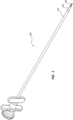
- FIG. 1 is a perspective view of a drainage catheter exchange system 100, according to one embodiment.
- the illustrated drainage catheter exchange system 100 comprises a locking stylet 130, a cutting tool 120, and a sheath 110.
- the drainage catheter exchange system 100 may also comprise a replacement catheter.
- the locking stylet 130 selectively couples to a catheter. More specifically, a distal portion of the locking stylet 130 is configured to selectively couple to a proximal portion of a catheter. In some embodiments, the locking stylet 130 engages the outer diameter of the proximal portion of the catheter. In some embodiments, the locking stylet 130 engages the inner diameter of the proximal portion of the catheter. Other locations and types of coupling between the locking stylet 130 and a catheter are also within the scope of this disclosure. Furthermore, in some instances, prior to coupling the locking stylet 130 to a catheter, a practitioner may cut or otherwise remove a hub from the catheter. In embodiments where the catheter has a proximal hub, removal of the hub may facilitate coupling of the locking stylet 130 directly to an elongate tube of the catheter.
- the locking stylet 130 may assist with catheter movement during a procedure to remove or replace a catheter.
- a physician may grasp a proximal portion of the locking stylet 130 to stabilize or secure the catheter, which may minimize undesired catheter movement (e.g., the catheter being pushed further into a patient by the cutting tool 120 and the sheath 110).
- the locking stylet 130 may be used by a physician to secure the placement of the catheter while the cutting tool 120 and the sheath 110 advance along the catheter.
- the locking stylet 130 may provide the physician with a grip that extends beyond the sheath 110 to remove the catheter without removing the sheath 110, thereby allowing the sheath to be used to introduce a replacement catheter. Further, the locking stylet 130 may function as a guide for placing the cutting tool 120 and the sheath 110 over the catheter.
- the cutting tool 120 may be configured to sever a suture securing a catheter in a pig-tail configuration.
- the cutting tool 120 may be a cylindrical device that can encompass and slide along the locking stylet 130 and the catheter.
- the cutting tool 120 may be a separate component from the sheath 110.
- the cutting tool 120 may be integrated into the sheath 110.
- the sheath 110 may have a sharpened edge.
- the sheath 110 is placed over the cutting tool 120 to provide a guard for the cutting tool 120.
- the cutting tool 120 may be longer than the sheath 110 and be able to slide longitudinally relative to the sheath 110, such that the distal portion of the cutting tool 120 may be disposed within, or exposed by, the sheath 110 based on the position of the cutting tool 120 relative to the sheath 110.
- the sheath 110 may minimize or prevent the cutting tool 120 from causing trauma to the patient while the cutting tool 120 and sheath 110 advance along the catheter.
- the sheath 110 may cover the cutting tool 120 such that the cutting tool 120 does not cut into tissue as the cutting tool 120 is advanced over the catheter.
- FIG. 2 is an exploded view of the drainage catheter exchange system 100 of FIG. 1 .
- the drainage catheter exchange system 100 comprises the locking stylet 130, the cutting tool 120, and the sheath 110.
- the locking stylet 130 is configured to be nested in the cutting tool 120, and the cutting tool 120 is configured to be nested in the sheath 110.
- the locking stylet 130 may be configured to be disposed within a lumen of the cutting tool 120 and the cutting tool 120 may be configured to be disposed within a lumen of the sheath 110.
- the sheath 110 may comprise a handle 214 and a shaft 212.
- the shaft 212 is flexible. The flexibility of the shaft 212 may facilitates movement along a catheter even if the catheter is bent or curved.
- the handle 214 provides a grip for a physician to advance or retract the sheath 110 along the catheter.
- the sheath 110 is splittable, to allow the sheath 110 to be removed from around a replacement catheter comprising a hub (as further discussed below).
- the cutting tool 120 comprises a cannula with a flexible shaft 224 and a cutter 222.
- the cutting tool 120 is configured to surround a catheter.
- the sheath 110 may be positioned around at least a portion of the cutting tool 120.
- the sheath 110 may cover the cutter 222 while the cutting tool 120 and the sheath 110 are advanced along a catheter to a suture of the catheter.
- the sheath 110 includes an aperture at the distal end of the flexible shaft 224, and at least a portion of the cutting tool 120 may be selectively extended through the aperture.
- the cutter 222 is at a distal end of the flexible shaft 224. Again, the cutter 222 may selectively transition between a first position in which the cutter 222 is within the sheath 110 and a second position in which the cutter 222 is extended beyond the sheath 110.
- the cutter 222 comprises a circular cutting blade at the distal end of the cutting tool 120.
- the circular cutting blade may be a sharpened edge around a circumference of the distal end of the flexible shaft 224.
- the cutter 222 comprises a series of serrations.
- the cutter 222 comprises a series of notches, including embodiments wherein each of the notches comprises a blunt distal tip and an angled portion that is sharpened. By blunting the distal tip of the notches, the cutter 222 may be configured to avoid cutting the patient when the cutter 222 is extended from the sheath 110.
- the cutter 222 may include a handle 226.
- the handle 226 provides a grip for a physician to advance or retract the cutting tool 120 along a catheter. Additionally, the physician may use the handle 226 to move the cutting tool 120 longitudinally in relation to the sheath 110 to expose the cutter 222 or sheath the cutter 222.
- the cutting tool 120 may selectively lock into a position relative to the sheath 110.
- the cutting tool 120 may be locked into a sheathed position where the cutter 222 is within the sheath 110.
- a physician may exert a deliberate force (e.g., a longitudinal force or a rotational force) to remove the cutting tool 120 from a locked position.
- the sheath 110 may prevent the cutting tool 120 from extending past a target distance.
- the handle 214 of the sheath 110 limits the longitudinal position of the handle 226 of the cutting tool 120.
- the cutter 222 is limited in its distance to advance beyond the sheath 110.
- the length of the flexible shaft 224 of the cutting tool 120 in relation to the length of the shaft 212 of the sheath 110 may determine the distance that the cutter 222 may advance beyond the sheath 110.
- the sheath 110 may be used to sever a suture of a catheter.
- a cutting portion may be integrated into the sheath 110.
- the sheath 110 may have a sharpened edge, serrations, or notches with a blunt distal tip and sharpened interior edges.
- the cutting tool 120 may not be included in the drainage catheter exchange system 100.
- Embodiments where the drainage catheter exchange system 100 does not include a cutter 222, cutting tool 120, or cutting portion of the sheath 110 are also within the scope of this disclosure. Without a cutting mechanism the drainage catheter exchange system 100 could still be used to exchange a catheter.
- the locking stylet 130 may be used to secure the old catheter while the sheath 110 is placed and to remove the old catheter through the sheath 110.
- the sheath 110 could be left in place and serve as an introducer for a new catheter.
- Such systems may be used when the suture is released from the hub (such as when the suture is not encrusted) or the sheath 110 may be pushed against the suture to displace or break the suture without the use of a cutting portion.
- the locking stylet 130 comprises a shaft 234, a locking mechanism 232, and a handle 236.
- the locking mechanism 232 is at a distal portion of the shaft 234, and the handle 236 is at a proximal end of the shaft 234.
- the locking mechanism 232 couples the distal portion of the shaft 234 of the locking stylet 130 to a proximal portion of a catheter.
- a physician may remove a hub of a catheter and use the locking mechanism 232 to couple the locking stylet 130 to the inner diameter or outer diameter of the catheter.
- the locking mechanism 232 may include one or more of a screw thread, fingers, or barbs.
- the locking mechanism 232 may comprise a screw thread to secure the locking stylet 130 to the catheter.
- the handle 236 of the locking stylet 130 may be used to apply a rotational force to the locking mechanism 232.
- the rotational force can cause the screw thread to engage an inner surface of the catheter when the locking mechanism 232 is inserted into a proximal opening of the catheter.
- the locking stylet 130 may be configured to be used on a variety of catheters of different sizes.
- catheters may range from 6 French (Fr) to 16 Fr.
- the locking stylet 130 may be sized for a specific catheter size.
- the locking stylet 130 could couple to a range of sizes of catheters.
- the locking mechanism 232 in the illustrated embodiment has a conical shape.
- the conical shape may have a tip with a diameter sized for a 6 Fr size catheter and widen to a diameter sized for a 9 Fr size catheter, for example.
- the locking stylet 130 may include a lumen. The lumen would allow the locking stylet 130 to be placed over a guidewire, including a guidewire previously disposed within the catheter.
- the locking stylet 130 may not include the handle 236. Without the handle 236, the sheath 110 and the cutting tool 120 may be placed over the locking stylet 130 after the locking stylet 130 has been coupled to the catheter. In some embodiments, the locking stylet 130 may be tapered on one or both ends.
- FIG. 3 is a detail view of the locking mechanism 232 of the locking stylet 130 of the drainage catheter exchange system 100 of FIG. 1 .
- the locking mechanism 232 comprises a helical thread around a conical tip.
- the helical thread is configured to engage an inner surface of a catheter when the conical tip is inserted into a proximal opening of the catheter and rotated.
- the rotated locking mechanism 232 may form a friction fit with the inner surface of the catheter.
- a physician may rotate the locking stylet 130 in an opposite direction (opposite the rotational direction used to couple the locking mechanism 232 to the catheter) to release the locking mechanism 232 from the catheter.
- the helical thread may be rounded to prevent tearing the catheter.
- the conical tip can couple to a drainage catheter with a range of sizes.
- the conical tip tapers out from the vertex of the tip.
- the conical tip features a diameter that progressively expands as the tip tapers away from the vertex of the tip.
- a smaller drainage catheter may be secured with the first and second revolutions of the helical thread, while a larger drainage catheter may be secured with the last several revolutions of the helical thread.
- a conical tip may be tapered to fit a catheter with a size between 9 Fr and 12 Fr.
- the conical tip may not be configured to taper to couple to a range of catheter sizes.
- the conical tip may still comprise a taper, but the tip geometry may be configured to couple to a single catheter size.
- the physician selects an appropriate-sized locking stylet 130 for the drainage catheter.
- a kit may include multiple locking stylets to accommodate different-sized catheters.
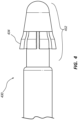
- FIG. 4 is detail view of a locking mechanism 432 of a locking stylet 430, according to a second embodiment.
- the locking mechanism 432 comprises a plurality of barbs 434 (which may also be referred to as push-in fingers) to engage an inner surface of the catheter when the locking stylet 430 is inserted into a proximal opening of the catheter.
- the plurality of barbs 434 are positioned around a distal portion of the locking stylet 430. Each of the plurality of barbs 434 extends proximally and away from a center of the locking stylet 430. Because the plurality of barbs 434 are sloped away from the distal end of the locking stylet 430, the locking mechanism 432 may be configured to be inserted into a proximal opening of the catheter without catching on an edge of the catheter.
- Each of the plurality of barbs 434 is connected to the locking stylet 430 along a single edge.
- Each of the plurality of barbs 434 may be able to flex inward toward the center of the locking stylet 430. When the plurality of barbs 434 are deflected inward, they may exert an outward spring force.
- the inner surface of the catheter deflects the plurality of barbs 434 inwardly.
- the plurality of barbs 434 may exert an outward spring force, causing the plurality of barbs 434 to engage with the inner surface of the catheter.
- the spring force may secure the locking mechanism 432 within the catheter.
- the plurality of barbs 434 may be formed in a variety of ways.
- the plurality of barbs 434 may be formed from the distal portion of the locking stylet 430.
- a portion of the locking stylet 430 may be removed to form integrated barbs.
- a cap comprising the plurality of barbs 434 may be coupled to the distal portion of the locking stylet 430.
- the diameter of the distal portion of the locking stylet 430 is smaller than the diameter of the proximal portion of the locking stylet 430.
- the smaller diameter of the distal portion provides space for the plurality of barbs 434 to flex inwardly toward the center of the locking stylet 430.
- the locking mechanism 432 can couple to a drainage catheter with a range of sizes.
- the plurality of barbs 434 may flair out from the center of the locking stylet 430.
- the outward extension of the plurality of barbs 434 may allow the locking mechanism 432 to couple to multiple diameters of catheter or may be configured to couple to a specific diameter catheter.
- a smaller diameter catheter would cause the plurality of barbs 434 to flex inwardly more than a larger diameter catheter; however, the spring force exerted by the plurality of barbs 434 on the larger diameter catheter may still be sufficient to couple the locking stylet 430 to the catheter.
- the plurality of barbs 434 are not configured to deflect to couple to a range of catheter sizes.
- the physician selects an appropriate-sized locking stylet 130.
- a kit may include multiple locking stylets to accommodate different catheter sizes.
- FIG. 5 is detail view of a locking mechanism 532 of a locking stylet 530, according to a third embodiment, which is in accordance with the claimed invention.
- the locking mechanism 532 comprises a plurality of barbs (i.e., first set of barbs 534 and second set of barbs 536) to engage an inner surface of the catheter when the locking stylet 530 is inserted into a proximal opening of the catheter.
- the barbs 534, 536 may also be referred to as push-in fingers.
- the shaft is hollow and the barbs 534, 536 comprise strips cut from the distal portion of the locking stylet 530.
- the barbs 534, 536 are bent outward from the locking stylet 530 and remain coupled to the locking stylet 530 along one edge.
- Each of the first set of barbs 534 remains attached to the locking stylet 530 along an edge of the barb closest to the distal end of the locking stylet 530.
- Each of the second set of barbs 536 remains attached to the locking stylet 530 along an edge of the barb closest to the proximal end of the locking stylet 530.
- the space between the first set of barbs 534 and the second set of barbs 536 may be left as an open slot 538.
- the first set of barbs 534 is positioned around the distal portion of the locking stylet 530 nearer the distal end than the second set of barbs 536. Each barb of the first set of barbs 534 extends proximally and away from a center of the locking stylet 530. Because the first set of barbs 534 is sloped away from the distal end of the locking stylet 530, the locking mechanism 532 may be inserted into a proximal opening of the catheter without catching on an edge of the catheter.
- Each barb of the first set of barbs 534 is connected to the locking stylet 530 along a single edge.
- Each of the plurality of barbs 434 may be able to flex inward toward the center of the locking stylet 530. When the plurality of barbs 534 are deflected inward, they may exert an outward spring force.
- the inner surface of the catheter deflects the first set of barbs 534 inwardly.
- the first set of barbs 534 may exert an outward spring force, causing the first set of barbs 534 to engage with the inner surface of the catheter.
- the spring force may secure the locking mechanism 532 within the catheter.
- the second set of barbs 536 is positioned around a distal portion of the locking stylet 530 nearer the proximal end than the first set of barbs 534. Each barb of the second set of barbs 536 extends distally and away from a center of the locking stylet 530. Because the second set of barbs 536 is sloped away from the proximal end of the locking stylet 530, the locking mechanism 532 may be used to secure an elongate cover to the locking stylet 530 as illustrated in FIG. 6 . Additionally or alternatively, the locking mechanism 532 can stop advancement of the catheter over the locking stylet 530.
- FIG. 6 is a perspective view of the locking stylet 530 of FIG. 5 with an elongate cover 640, according to one embodiment.
- the elongate cover 640 may comprise an extruded member and may be secured in place via a set of barbs as shown in FIG. 5 .
- the elongate cover 640 may be flexible and surround a shaft of the locking stylet 530.
- the locking stylet 530 may include a tapered proximal portion 642. As shown, the locking stylet 530 may not include a handle. Instead, in some embodiments, the locking stylet 530 may be tapered on one or both ends (e.g., tapered proximal portion 642). The tapered proximal portion 642 may allow the locking stylet 530 to be easily inserted into a sheath even if the locking stylet 530 is already secured to a catheter.
- FIG. 7 is a side view of a cutting tool 120 of the drainage catheter exchange system 100 of FIG. 1 .
- the cutting tool 120 includes a hollow cannula with a cutter 222 on a distal edge.
- the the cutting tool 120 may be a hollow cannula and may comprise an single integral piece, such as a integral metal cannula.
- the cutter 222 is a sharpened distal edge of a hollow cannula.
- the cutter 222 may be separate from the cannula.
- the cutter 222 may be embedded, glued, or otherwise coupled to the distal edge of the cannula.
- the cutting tool 120 includes one or more laser cut spirals along the hollow cannula. Spiral cuts, or other features may be disposed along the cutting tool 120 to increase the flexibility of the cutting tool 120 to traverse along a catheter and follow the path of the catheter. In some embodiments, one or more spiral cuts on the cutting tool 120 may have equal distance between rotations. In some embodiments, one or more spiral cuts along the cutting tool 120 may vary in pitch or density. In other words, the distance between rotations of one or more spiral cuts may vary across the length of the cutting tool 120. Variation in spiral cut density provides the cutting tool 120 with a flexibility profile that varies along a length of the cutting tool 120.
- the cutting tool 120 features two flexible sections (i.e., distal flexible section 722 and proximal flexible section 724).
- the distal flexible section 722 includes more rotations per length of the spiral cut than the proximal flexible section 724.
- the closer spiral cuts of the distal flexible section 722 may have a higher pitch than the further apart spiral cuts of the proximal flexible section 724.
- the greater density of the spiral cut along the distal flexible section 722 provides the distal flexible section 722 with a greater flexibility than the proximal flexible section 724.
- the greater flexibility of the distal flexible section 722 allows the tip of the cutting tool 120 to track the path of the catheter more readily.
- the distal flexible section 722 may be configured to track the catheter around a tight radius and may be configured to transition and lead proximal flexible section 724 over such a path. In other words, the distal flexible section 722 can guide the proximal flexible section 724 around such tight turns. After the distal flexible section 722 follows a radius the rest of the cannula will follow even if the rest of cannula may distort that radius (or tend to straighten the catheter). Further, the cutting tool 120 may be configured such that the distal flexible section 722 is configured to be disposed over more tortuous curvature than other portions of the cutting tool 120.
- the distal flexible section 722 features a first spiral cut and the proximal flexible section 724 features a second spiral cut.
- the first spiral cut has a pitch in the opposite direction of the second spiral cut.
- the two spiral cuts are joined.
- the spiral cuts are discrete.
- the pitch of the spiral cuts may be in the same direction.
- the one or more spiral cuts may be cut uniformly to create a flexibility profile of the cutting tool 120 with the same flexibility throughout.
- the cutting tool 120 may feature three or more sections with varying flexibility.
- the density of the one or more spiral cuts may gradually change from one end of the cutting tool 120 to another end of the cutting tool 120.
- the spiral cut may be dense at a distal portion of the cutting tool and gradually the rotations of the cutting tool 120 may widen as the spiral cut approaches a proximal portion of the cutting tool 120.
- FIG. 8 is a cross-sectional view of a distal portion of the cutter 222 of FIG. 7 .
- the cutter 222 includes a first bevel 821 extending from the outer diameter of the cutting tool sidewall to the inner diameter of the cutting tool sidewall, and a second bevel 822 extending from the inner diameter of the cutting tool sidewall to the outer diameter of the cutting tool sidewall.
- the angles shown on FIG. 8 are exemplary and may be changed to any suitable angle.
- the first bevel 821 and the second bevel 822 meet at a vertex that forms the sharpened edge of the cutter 222.
- the vertex is in between the outer diameter of the cutting tool sidewall and the inner diameter of the cutting tool sidewall to avoid damaging a sheath outside of the cutter 222 or a catheter inside the cutter 222.
- the first bevel 821 may displace the cutting edge away from an outer sheath and the second bevel 822 may displace the cutting edge away from the catheter, to reduce or avoid skiving of the catheter and the cutter 222 is advanced along the catheter.
- FIGS. 9A and 9B illustrate the drainage catheter exchange system 100 of FIG. 1 in use.
- FIG. 9A is a schematic representation of the drainage catheter exchange system 100 of FIG. 1 being inserted into a patient to remove a drainage catheter 900.
- FIG. 9B is a schematic representation of the drainage catheter exchange system 100 of FIG. 1 severing a suture 902 of the drainage catheter 900.
- the drainage catheter exchange system 100 may facilitate removal of the drainage catheter 900 even when the suture 902 has become encrusted.
- the sheath 110 and the cutting tool 120 are inserted into a patient over a previously placed drainage catheter 900.
- the locking stylet 130 may couple to the proximal end of the drainage catheter 900.
- a physician may hold onto a shaft of the drainage catheter 900 or a handle of the drainage catheter 900 to limit movement of the drainage catheter 900.
- practitioner may cut or otherwise remove a hub from the drainage catheter 900 to facilitate advancing the sheath 100 over the drainage catheter 900 and to facilitate coupling of the locking stylet 130 to the drainage catheter.
- the physician advances the sheath 110 and the cutting tool 120 along the drainage catheter 900 to near the suture 902.
- the physician may apply a longitudinal force to the handle 214 of the sheath 110 and the handle 226 of the cutting tool 120 to advance the sheath 110 and the cutting tool 120.
- the physician may track the position of the sheath 110 and the cutting tool 120 relative to the suture 902 using fluoroscopy, ultrasound, or measurement.
- the cutting tool 120 may be advanced from the sheath 110 to sever the suture 902.
- the physician may withdraw the drainage catheter 900 by pulling the locking stylet 130 away from the sheath 110 and the handle 226.
- the physician may also remove the cutting tool 120 and leave the sheath 110 in the patient to serve as an introducer for a new drainage catheter.
- the sheath 110 is splittable, so that once the new drainage catheter is in place, the physician may split the sheath 110 to remove it from the patient if the new drainage catheter comprises a hub.
- FIG. 10 is a flow chart of a method 1000 for removing a catheter using a drainage catheter exchange system.
- the method includes coupling 1002 the catheter to a stylet.
- the stylet includes a shaft and a locking mechanism at a distal portion of the shaft.
- the locking mechanism may be any of the locking mechanisms described herein or any other suitable securement means.
- a physician may remove a hub of the catheter and couple the locking mechanism to the distal portion of the shaft to a proximal portion of a catheter.
- the physician may secure 1004 the position of the catheter via the shaft of the stylet by holding the stylet in place.
- the physician may advance 1006 a sheath along a length of the catheter and sever 1008 a suture on a distal portion of the catheter.
- the physician may remove 1010 the catheter through the sheath by pulling on the locking stylet.
- severing 1008 the suture comprises applying a force to the suture via the sheath.
- severing 1008 the suture comprises extending a cutting tool beyond the sheath.
- the method may further comprise placing a new catheter through the sheath, and removing the sheath and the cutter.
- the sheath may be removed by splitting the sheath away from a hub of the new catheter.
- Any methods disclosed herein include one or more steps or actions for performing the described method.
- the method steps and/or actions may be interchanged with one another.
- the order and/or use of specific steps and/or actions may be modified.
- sub-routines or only a portion of a method described herein may be a separate method within the scope of this disclosure. Stated otherwise, some methods may include only a portion of the steps described in a more detailed method.
Landscapes
- Health & Medical Sciences (AREA)
- Life Sciences & Earth Sciences (AREA)
- Surgery (AREA)
- Animal Behavior & Ethology (AREA)
- General Health & Medical Sciences (AREA)
- Engineering & Computer Science (AREA)
- Biomedical Technology (AREA)
- Heart & Thoracic Surgery (AREA)
- Veterinary Medicine (AREA)
- Public Health (AREA)
- Medical Informatics (AREA)
- Molecular Biology (AREA)
- Nuclear Medicine, Radiotherapy & Molecular Imaging (AREA)
- Pathology (AREA)
- Gastroenterology & Hepatology (AREA)
- Biophysics (AREA)
- Pulmonology (AREA)
- Anesthesiology (AREA)
- Hematology (AREA)
- Media Introduction/Drainage Providing Device (AREA)
Claims (8)
- Katheterwechselsystem (100), umfassend:eine Kanüle, wobei die Kanüle einen biegsamen Schaft (224) und eine Schneideinrichtung (222) an einem distalen Ende des biegsamen Schafts umfasst; undeinen Mantel (110), der um mindestens einen Abschnitt der Kanüle positioniert ist;wobei die Schneideinrichtung (222) selektiv zwischen einer ersten Stellung, in der sich die Schneideinrichtung innerhalb des Mantels befindet, und einer zweiten Stellung, in der sich die Schneideinrichtung über den Mantel hinaus erstreckt, wechseln kann,dadurch gekennzeichnet, dass das System (100) ferner Folgendes umfasst:
einen Mandrin (530), umfassend:einen Schaft undeinen Arretiermechanismus (532) an einem distalen Abschnitt des Schafts;wobei der Arretiermechanismus einen oder mehrere in einer Wand des Schafts gebildete Widerhaken (534, 536) umfasst;wobei der eine oder die mehreren Widerhaken von dem Schaft aus nach außen gespannt sind;wobei der Arretiermechanismus dazu konfiguriert ist, den distalen Abschnitt des Schafts an einen proximalen Abschnitt eines Katheters zu koppeln;wobei der eine oder die mehreren Widerhaken einen ersten Satz von Widerhaken (534) und einen zweiten Satz von Widerhaken (536) umfassen;wobei der erste Satz von Widerhaken distal orientiert ist und der zweite Satz von Widerhaken proximal orientiert ist;wobei jeder des ersten Satzes von Widerhaken (534) dazu konfiguriert ist, entlang einer des dem distalen Ende des Mandrins am nächsten gelegenen Kante des Widerhakens an dem Mandrin angebracht zu bleiben, undwobei jeder des zweiten Satzes von Widerhaken (536) dazu konfiguriert ist, entlang einer des dem proximalen Ende des Mandrins am nächsten gelegenen Kante des Widerhakens an dem Mandrin angebracht zu bleiben. - System (100) nach Anspruch 1, wobei die Schneideinrichtung ein kreisförmiges Schneidmesser umfasst.
- System (100) nach Anspruch 2, wobei es sich bei dem kreisförmigen Schneidmesser um eine geschärfte Kante um einen Umfang des distalen Endes des biegsamen Schafts handelt.
- System (100) nach Anspruch 2, wobei die Schneideinrichtung eine Reihe von Zähnen umfasst.
- System (100) nach Anspruch 2, wobei die Schneideinrichtung eine Reihe von Kerben umfasst, die eine distale Spitze und einen schrägen Abschnitt umfassen, wobei die distale Spitze stumpf ist und die schrägen Abschnitte geschärft sind.
- System (100) nach einem der Ansprüche 1-5, wobei der Mantel spaltbar ist.
- System (100) nach einem der Ansprüche 1-6, wobei die Kanüle einen oder mehrere Spiralschnitte entlang einer Länge umfasst.
- System (100) nach Anspruch 7, wobei ein Abstand zwischen Umläufen des einen oder mehreren Spiralschnitte an einem distalen Abschnitt der Kanüle geringer als der Abstand zwischen Umläufen des einen oder der mehreren Spiralschnitte an einem proximalen Abschnitt ist.
Applications Claiming Priority (2)
| Application Number | Priority Date | Filing Date | Title |
|---|---|---|---|
| US201962846180P | 2019-05-10 | 2019-05-10 | |
| PCT/US2020/031911 WO2020231748A1 (en) | 2019-05-10 | 2020-05-07 | Drainage catheter exchange system and associated methods |
Publications (3)
| Publication Number | Publication Date |
|---|---|
| EP3965861A1 EP3965861A1 (de) | 2022-03-16 |
| EP3965861A4 EP3965861A4 (de) | 2023-01-18 |
| EP3965861B1 true EP3965861B1 (de) | 2024-11-27 |
Family
ID=73047361
Family Applications (1)
| Application Number | Title | Priority Date | Filing Date |
|---|---|---|---|
| EP20805546.7A Active EP3965861B1 (de) | 2019-05-10 | 2020-05-07 | Drainagekatheteraustauschsystem |
Country Status (3)
| Country | Link |
|---|---|
| US (1) | US11717319B2 (de) |
| EP (1) | EP3965861B1 (de) |
| WO (1) | WO2020231748A1 (de) |
Families Citing this family (1)
| Publication number | Priority date | Publication date | Assignee | Title |
|---|---|---|---|---|
| US20220218963A1 (en) * | 2021-01-12 | 2022-07-14 | Rhode Island Hospital | Surgical drain removal device and methods for using same |
Family Cites Families (66)
| Publication number | Priority date | Publication date | Assignee | Title |
|---|---|---|---|---|
| US2242831A (en) | 1938-09-12 | 1941-05-20 | Imp Brass Mfg Co | Flaring tool |
| US2876496A (en) | 1955-12-16 | 1959-03-10 | Dade Reagents Inc | Process for making tubes |
| US3094124A (en) | 1960-06-30 | 1963-06-18 | Davol Rubber Co | Arterial catheter |
| US4068515A (en) | 1977-02-07 | 1978-01-17 | Gould Inc. | Flaring tool |
| US4264294A (en) | 1979-01-08 | 1981-04-28 | Ruiz Oscar F | Profiling die |
| US4256106A (en) | 1979-04-30 | 1981-03-17 | Becton, Dickinson And Company | Resealable device |
| US4402136A (en) | 1979-07-18 | 1983-09-06 | Rast Patent Manufacturers Pty. Limited | Device for cutting pipes |
| US4430081A (en) | 1981-01-06 | 1984-02-07 | Cook, Inc. | Hemostasis sheath |
| AU2088683A (en) | 1982-11-18 | 1984-05-24 | Abbott Laboratories | Catheter assembly |
| US4535616A (en) | 1983-04-08 | 1985-08-20 | Dowley Manufacturing, Inc. | Flaring tool |
| DE3521697A1 (de) | 1984-06-18 | 1986-02-20 | Tetsushi Ichihara Chiba Kubo | Rohrbearbeitungsvorrichtung |
| DE3621399A1 (de) | 1986-06-26 | 1988-01-14 | Beermann Kg Martor Argentax | Vorrichtung zum abschneiden von im wesentlichen zylindrischen elementen |
| US4813260A (en) | 1987-04-27 | 1989-03-21 | Clevite Industries Inc. | Multipurpose tube working tool |
| US5020221A (en) | 1987-10-22 | 1991-06-04 | Nelson Clifford P | Pipe chamfer and deburring tool |
| US5380304A (en) | 1991-08-07 | 1995-01-10 | Cook Incorporated | Flexible, kink-resistant, introducer sheath and method of manufacture |
| US8753317B2 (en) | 1992-05-06 | 2014-06-17 | Cook Medical Technologies Llc | Hemostasis cannula |
| US5221263A (en) | 1992-07-30 | 1993-06-22 | Gesco International, Inc. | Catheter emplacement apparatus |
| US5267966A (en) | 1992-09-28 | 1993-12-07 | Cook Incorporated | Hemostasis cannula and method of making a valve for same |
| US5283951A (en) | 1992-12-17 | 1994-02-08 | Curtis Products, Inc. | Method of producing a tubing for use as a flow conduit |
| US5308318A (en) * | 1993-05-07 | 1994-05-03 | Plassche Jr Walter M | Easy-exchange drainage catheter system with integral obturator channel |
| US5645539A (en) | 1994-11-14 | 1997-07-08 | Innocare One, Ltd. | Elongated medical channel assembly and method of preventing dislodgement |
| US5651781A (en) | 1995-04-20 | 1997-07-29 | Grace-Wells Technology Partners No. 1, L.P. | Surgical cutting instrument |
| USD372782S (en) | 1995-05-12 | 1996-08-13 | Luther Medical Products, Inc. | Catheter field trimming device |
| US6496561B1 (en) * | 1998-03-06 | 2002-12-17 | Medtronic Ave, Inc. | Devices, methods and systems for delivery of X-ray |
| US6428498B2 (en) | 1998-04-14 | 2002-08-06 | Renan Uflacker | Suction catheter for rapidly debriding abscesses |
| US6872198B1 (en) | 2001-01-24 | 2005-03-29 | Arrow International, Inc. | Double-y-shaped multi-lumen catheter with selectively attachable hubs |
| US7300430B2 (en) | 2001-01-24 | 2007-11-27 | Arrow International, Inc. | Multi-lumen catheter with attachable hub |
| US6994009B2 (en) | 2001-05-16 | 2006-02-07 | Sam W. Carter | Powered pipe cutter |
| US6832536B2 (en) | 2002-05-21 | 2004-12-21 | Exotic Metal Forming Company | Machine and method for servering a thin-walled tube |
| DE03764480T1 (de) * | 2002-07-12 | 2005-10-20 | Cook Urological Inc | Flexibler kanülenstiel |
| US20040040796A1 (en) | 2002-08-27 | 2004-03-04 | Nghi Pham | Backing plate with friction material retention members and method and apparatus for manufacturing same |
| US20040133124A1 (en) * | 2003-01-06 | 2004-07-08 | Cook Incorporated. | Flexible biopsy needle |
| US7182746B2 (en) | 2003-03-28 | 2007-02-27 | Sherwood Services Ag | Reversible lumen catheter |
| US7879024B2 (en) * | 2003-06-26 | 2011-02-01 | St. Jude Medical, Atrial Fibrillation Division, Inc. | Splittable cannula having radiopaque marker |
| US20050159676A1 (en) * | 2003-08-13 | 2005-07-21 | Taylor James D. | Targeted biopsy delivery system |
| US7615057B2 (en) | 2004-02-12 | 2009-11-10 | Cardiac Pacemakers, Inc. | Notched cutter for guide catheter removal from lead |
| US7594910B2 (en) | 2004-03-18 | 2009-09-29 | C. R. Bard, Inc. | Catheter connector |
| US7578803B2 (en) * | 2004-03-18 | 2009-08-25 | C. R. Bard, Inc. | Multifunction adaptor for an open-ended catheter |
| US20060137973A1 (en) | 2004-11-24 | 2006-06-29 | Miox Corporation | Device and method for instrument steralization |
| US7462167B2 (en) | 2005-01-26 | 2008-12-09 | Thomas Medical Products, Inc. | Catheter sheath slitter and method of use |
| AU2006212750B2 (en) | 2005-02-07 | 2011-11-17 | Evalve, Inc. | Methods, systems and devices for cardiac valve repair |
| US7641630B2 (en) | 2005-03-11 | 2010-01-05 | Merit Medical Systems, Inc. | Drainage catheter hub with locking cam |
| US7740616B2 (en) | 2005-03-29 | 2010-06-22 | Angiodynamics, Inc. | Implantable catheter and method of using same |
| WO2006113438A2 (en) | 2005-04-15 | 2006-10-26 | Cook Vascular Incorporated | Lead extraction device |
| US20070175048A1 (en) | 2006-01-31 | 2007-08-02 | Tycohealthcare Group Lp | Medical apparatus for cutting medical tubes |
| US20080236358A1 (en) | 2007-03-27 | 2008-10-02 | Vitullo Jeffrey M | Catheter trimmer |
| US20090158597A1 (en) | 2007-12-20 | 2009-06-25 | Tyco Healthcare Group Lp | Medical Tubing Cutter |
| US7938809B2 (en) | 2008-04-14 | 2011-05-10 | Merit Medical Systems, Inc. | Quick release hemostasis valve |
| US9962523B2 (en) | 2008-06-27 | 2018-05-08 | Merit Medical Systems, Inc. | Catheter with radiopaque marker |
| US8006594B2 (en) | 2008-08-11 | 2011-08-30 | Cardiac Dimensions, Inc. | Catheter cutting tool |
| US8708897B2 (en) | 2008-09-08 | 2014-04-29 | Covidien Lp | Tunneling system |
| US8109939B2 (en) * | 2009-03-27 | 2012-02-07 | Hazem Barmada | System and method for removing an implanted catheter from a patient |
| US8057403B2 (en) * | 2009-05-29 | 2011-11-15 | Promex Technologies, Inc. | Flexible biopsy needle |
| US20100317996A1 (en) * | 2009-06-10 | 2010-12-16 | Dillon Travis E | Ultrasound-navigable barbed biopsy device and method |
| US8337484B2 (en) | 2009-06-26 | 2012-12-25 | C. R. Band, Inc. | Proximally trimmable catheter including pre-attached bifurcation and related methods |
| US20110190734A1 (en) * | 2010-02-03 | 2011-08-04 | Richard Graffam | Mechanical Advantage For Hub Linear Travel For A Drainage Catheter |
| AR076937A3 (es) | 2010-06-01 | 2011-07-20 | Macroplast S A | Una herramienta manual cortadora/refiladora de tubos flexibles de bajo espesor |
| JP2013538624A (ja) * | 2010-09-20 | 2013-10-17 | スパイン ビュー, インコーポレイテッド | カニューレ挿入型切開刀 |
| US8607428B2 (en) | 2011-03-31 | 2013-12-17 | Angiodynamics, Inc. | Implantable catheter and method of using same |
| WO2014159431A1 (en) * | 2013-03-13 | 2014-10-02 | Boston Scientific Scimed, Inc. | Drainage catheter with cutting tool |
| US9980743B2 (en) | 2013-03-15 | 2018-05-29 | The Spectranetics Corporation | Medical device for removing an implanted object using laser cut hypotubes |
| WO2015095281A1 (en) * | 2013-12-17 | 2015-06-25 | The Trustees Of The University Of Pennsylvania | Apparatus, system and method for preventing retention of surgical drains |
| MX381268B (es) * | 2014-03-17 | 2025-03-12 | Arkis Biosciences Inc | Alambre guía de tunelización. |
| WO2015183663A1 (en) * | 2014-05-30 | 2015-12-03 | Cook Medical Technologies Llc | Laser cut needle cannula with increased flexibility |
| US10463351B2 (en) * | 2014-10-15 | 2019-11-05 | Cook Medical Technologies Llc | Transitional geometry for an expandable medical device |
| US20160361088A1 (en) * | 2015-06-12 | 2016-12-15 | Covidien Lp | Catheter with pre-formed geometry for body lumen access |
-
2020
- 2020-05-07 US US16/869,342 patent/US11717319B2/en active Active
- 2020-05-07 WO PCT/US2020/031911 patent/WO2020231748A1/en not_active Ceased
- 2020-05-07 EP EP20805546.7A patent/EP3965861B1/de active Active
Also Published As
| Publication number | Publication date |
|---|---|
| EP3965861A4 (de) | 2023-01-18 |
| WO2020231748A1 (en) | 2020-11-19 |
| US20200352594A1 (en) | 2020-11-12 |
| US11717319B2 (en) | 2023-08-08 |
| EP3965861A1 (de) | 2022-03-16 |
Similar Documents
| Publication | Publication Date | Title |
|---|---|---|
| US8814832B1 (en) | Expandable sheath and system for intravascular insertion of a medical implement using the same | |
| EP3180064B1 (de) | Expandierbare hülle und system zur intravaskulären einführung einer medizinischen vorrichtung damit | |
| US10507304B2 (en) | Catheter devices, kits and methods | |
| US6494860B2 (en) | Introducer with multiple sheaths and method of use therefor | |
| US5139511A (en) | Expansible cannula | |
| JP4667376B2 (ja) | 小ゲージ針カテーテル挿入器具 | |
| EP2197367B1 (de) | Spitze für eine leitungsextraktionsvorrichtung | |
| EP0522735B1 (de) | Verriegelungsdilatator für ablösbare Einführungshülse | |
| US4582056A (en) | Endocardial lead extraction apparatus and method | |
| EP0162982B1 (de) | Katheterhülle | |
| WO1985004320A1 (en) | Endocardial lead extraction apparatus and method | |
| AU2008279384A1 (en) | Catheter tunneler | |
| US11701143B2 (en) | Catheter devices, needle assemblies, kits and methods | |
| EP3965861B1 (de) | Drainagekatheteraustauschsystem | |
| US8257422B2 (en) | Over-the-wire detachment mechanism |
Legal Events
| Date | Code | Title | Description |
|---|---|---|---|
| STAA | Information on the status of an ep patent application or granted ep patent |
Free format text: STATUS: THE INTERNATIONAL PUBLICATION HAS BEEN MADE |
|
| PUAI | Public reference made under article 153(3) epc to a published international application that has entered the european phase |
Free format text: ORIGINAL CODE: 0009012 |
|
| STAA | Information on the status of an ep patent application or granted ep patent |
Free format text: STATUS: REQUEST FOR EXAMINATION WAS MADE |
|
| 17P | Request for examination filed |
Effective date: 20211028 |
|
| AK | Designated contracting states |
Kind code of ref document: A1 Designated state(s): AL AT BE BG CH CY CZ DE DK EE ES FI FR GB GR HR HU IE IS IT LI LT LU LV MC MK MT NL NO PL PT RO RS SE SI SK SM TR |
|
| DAV | Request for validation of the european patent (deleted) | ||
| DAX | Request for extension of the european patent (deleted) | ||
| A4 | Supplementary search report drawn up and despatched |
Effective date: 20221221 |
|
| RIC1 | Information provided on ipc code assigned before grant |
Ipc: A61B 17/34 20060101ALI20221215BHEP Ipc: A61M 25/02 20060101ALI20221215BHEP Ipc: A61M 25/00 20060101ALI20221215BHEP Ipc: A61M 25/01 20060101AFI20221215BHEP |
|
| STAA | Information on the status of an ep patent application or granted ep patent |
Free format text: STATUS: EXAMINATION IS IN PROGRESS |
|
| 17Q | First examination report despatched |
Effective date: 20231207 |
|
| REG | Reference to a national code |
Ref country code: DE Ref legal event code: R079 Free format text: PREVIOUS MAIN CLASS: A61M0025010000 Ipc: A61B0017000000 Ref country code: DE Ref legal event code: R079 Ref document number: 602020042162 Country of ref document: DE Free format text: PREVIOUS MAIN CLASS: A61M0025010000 Ipc: A61B0017000000 |
|
| GRAP | Despatch of communication of intention to grant a patent |
Free format text: ORIGINAL CODE: EPIDOSNIGR1 |
|
| STAA | Information on the status of an ep patent application or granted ep patent |
Free format text: STATUS: GRANT OF PATENT IS INTENDED |
|
| RIC1 | Information provided on ipc code assigned before grant |
Ipc: A61M 25/06 20060101ALI20240531BHEP Ipc: A61M 25/02 20060101ALI20240531BHEP Ipc: A61M 25/01 20060101ALI20240531BHEP Ipc: A61M 25/00 20060101ALI20240531BHEP Ipc: A61B 17/34 20060101ALI20240531BHEP Ipc: A61B 17/3205 20060101ALI20240531BHEP Ipc: A61B 17/00 20060101AFI20240531BHEP |
|
| INTG | Intention to grant announced |
Effective date: 20240618 |
|
| GRAS | Grant fee paid |
Free format text: ORIGINAL CODE: EPIDOSNIGR3 |
|
| GRAA | (expected) grant |
Free format text: ORIGINAL CODE: 0009210 |
|
| STAA | Information on the status of an ep patent application or granted ep patent |
Free format text: STATUS: THE PATENT HAS BEEN GRANTED |
|
| P01 | Opt-out of the competence of the unified patent court (upc) registered |
Free format text: CASE NUMBER: APP_55207/2024 Effective date: 20241008 |
|
| AK | Designated contracting states |
Kind code of ref document: B1 Designated state(s): AL AT BE BG CH CY CZ DE DK EE ES FI FR GB GR HR HU IE IS IT LI LT LU LV MC MK MT NL NO PL PT RO RS SE SI SK SM TR |
|
| REG | Reference to a national code |
Ref country code: GB Ref legal event code: FG4D |
|
| REG | Reference to a national code |
Ref country code: CH Ref legal event code: EP |
|
| REG | Reference to a national code |
Ref country code: IE Ref legal event code: FG4D |
|
| REG | Reference to a national code |
Ref country code: DE Ref legal event code: R096 Ref document number: 602020042162 Country of ref document: DE |
|
| REG | Reference to a national code |
Ref country code: LT Ref legal event code: MG9D |
|
| REG | Reference to a national code |
Ref country code: NL Ref legal event code: MP Effective date: 20241127 |
|
| PG25 | Lapsed in a contracting state [announced via postgrant information from national office to epo] |
Ref country code: PT Free format text: LAPSE BECAUSE OF FAILURE TO SUBMIT A TRANSLATION OF THE DESCRIPTION OR TO PAY THE FEE WITHIN THE PRESCRIBED TIME-LIMIT Effective date: 20250327 Ref country code: IS Free format text: LAPSE BECAUSE OF FAILURE TO SUBMIT A TRANSLATION OF THE DESCRIPTION OR TO PAY THE FEE WITHIN THE PRESCRIBED TIME-LIMIT Effective date: 20250327 Ref country code: HR Free format text: LAPSE BECAUSE OF FAILURE TO SUBMIT A TRANSLATION OF THE DESCRIPTION OR TO PAY THE FEE WITHIN THE PRESCRIBED TIME-LIMIT Effective date: 20241127 |
|
| PG25 | Lapsed in a contracting state [announced via postgrant information from national office to epo] |
Ref country code: FI Free format text: LAPSE BECAUSE OF FAILURE TO SUBMIT A TRANSLATION OF THE DESCRIPTION OR TO PAY THE FEE WITHIN THE PRESCRIBED TIME-LIMIT Effective date: 20241127 Ref country code: NL Free format text: LAPSE BECAUSE OF FAILURE TO SUBMIT A TRANSLATION OF THE DESCRIPTION OR TO PAY THE FEE WITHIN THE PRESCRIBED TIME-LIMIT Effective date: 20241127 |
|
| REG | Reference to a national code |
Ref country code: AT Ref legal event code: MK05 Ref document number: 1744922 Country of ref document: AT Kind code of ref document: T Effective date: 20241127 |
|
| PG25 | Lapsed in a contracting state [announced via postgrant information from national office to epo] |
Ref country code: BG Free format text: LAPSE BECAUSE OF FAILURE TO SUBMIT A TRANSLATION OF THE DESCRIPTION OR TO PAY THE FEE WITHIN THE PRESCRIBED TIME-LIMIT Effective date: 20241127 |
|
| PG25 | Lapsed in a contracting state [announced via postgrant information from national office to epo] |
Ref country code: ES Free format text: LAPSE BECAUSE OF FAILURE TO SUBMIT A TRANSLATION OF THE DESCRIPTION OR TO PAY THE FEE WITHIN THE PRESCRIBED TIME-LIMIT Effective date: 20241127 |
|
| PG25 | Lapsed in a contracting state [announced via postgrant information from national office to epo] |
Ref country code: NO Free format text: LAPSE BECAUSE OF FAILURE TO SUBMIT A TRANSLATION OF THE DESCRIPTION OR TO PAY THE FEE WITHIN THE PRESCRIBED TIME-LIMIT Effective date: 20250227 |
|
| PG25 | Lapsed in a contracting state [announced via postgrant information from national office to epo] |
Ref country code: LV Free format text: LAPSE BECAUSE OF FAILURE TO SUBMIT A TRANSLATION OF THE DESCRIPTION OR TO PAY THE FEE WITHIN THE PRESCRIBED TIME-LIMIT Effective date: 20241127 Ref country code: AT Free format text: LAPSE BECAUSE OF FAILURE TO SUBMIT A TRANSLATION OF THE DESCRIPTION OR TO PAY THE FEE WITHIN THE PRESCRIBED TIME-LIMIT Effective date: 20241127 Ref country code: GR Free format text: LAPSE BECAUSE OF FAILURE TO SUBMIT A TRANSLATION OF THE DESCRIPTION OR TO PAY THE FEE WITHIN THE PRESCRIBED TIME-LIMIT Effective date: 20250228 |
|
| PG25 | Lapsed in a contracting state [announced via postgrant information from national office to epo] |
Ref country code: PL Free format text: LAPSE BECAUSE OF FAILURE TO SUBMIT A TRANSLATION OF THE DESCRIPTION OR TO PAY THE FEE WITHIN THE PRESCRIBED TIME-LIMIT Effective date: 20241127 |
|
| PG25 | Lapsed in a contracting state [announced via postgrant information from national office to epo] |
Ref country code: RS Free format text: LAPSE BECAUSE OF FAILURE TO SUBMIT A TRANSLATION OF THE DESCRIPTION OR TO PAY THE FEE WITHIN THE PRESCRIBED TIME-LIMIT Effective date: 20250227 |
|
| PG25 | Lapsed in a contracting state [announced via postgrant information from national office to epo] |
Ref country code: SM Free format text: LAPSE BECAUSE OF FAILURE TO SUBMIT A TRANSLATION OF THE DESCRIPTION OR TO PAY THE FEE WITHIN THE PRESCRIBED TIME-LIMIT Effective date: 20241127 |
|
| PGFP | Annual fee paid to national office [announced via postgrant information from national office to epo] |
Ref country code: DE Payment date: 20250311 Year of fee payment: 6 |
|
| PG25 | Lapsed in a contracting state [announced via postgrant information from national office to epo] |
Ref country code: DK Free format text: LAPSE BECAUSE OF FAILURE TO SUBMIT A TRANSLATION OF THE DESCRIPTION OR TO PAY THE FEE WITHIN THE PRESCRIBED TIME-LIMIT Effective date: 20241127 |
|
| PGFP | Annual fee paid to national office [announced via postgrant information from national office to epo] |
Ref country code: IT Payment date: 20250422 Year of fee payment: 6 |
|
| PG25 | Lapsed in a contracting state [announced via postgrant information from national office to epo] |
Ref country code: EE Free format text: LAPSE BECAUSE OF FAILURE TO SUBMIT A TRANSLATION OF THE DESCRIPTION OR TO PAY THE FEE WITHIN THE PRESCRIBED TIME-LIMIT Effective date: 20241127 |
|
| PG25 | Lapsed in a contracting state [announced via postgrant information from national office to epo] |
Ref country code: RO Free format text: LAPSE BECAUSE OF FAILURE TO SUBMIT A TRANSLATION OF THE DESCRIPTION OR TO PAY THE FEE WITHIN THE PRESCRIBED TIME-LIMIT Effective date: 20241127 |
|
| PG25 | Lapsed in a contracting state [announced via postgrant information from national office to epo] |
Ref country code: SK Free format text: LAPSE BECAUSE OF FAILURE TO SUBMIT A TRANSLATION OF THE DESCRIPTION OR TO PAY THE FEE WITHIN THE PRESCRIBED TIME-LIMIT Effective date: 20241127 |
|
| PG25 | Lapsed in a contracting state [announced via postgrant information from national office to epo] |
Ref country code: CZ Free format text: LAPSE BECAUSE OF FAILURE TO SUBMIT A TRANSLATION OF THE DESCRIPTION OR TO PAY THE FEE WITHIN THE PRESCRIBED TIME-LIMIT Effective date: 20241127 |
|
| REG | Reference to a national code |
Ref country code: DE Ref legal event code: R097 Ref document number: 602020042162 Country of ref document: DE |
|
| PG25 | Lapsed in a contracting state [announced via postgrant information from national office to epo] |
Ref country code: SE Free format text: LAPSE BECAUSE OF FAILURE TO SUBMIT A TRANSLATION OF THE DESCRIPTION OR TO PAY THE FEE WITHIN THE PRESCRIBED TIME-LIMIT Effective date: 20241127 |
|
| PLBE | No opposition filed within time limit |
Free format text: ORIGINAL CODE: 0009261 |
|
| STAA | Information on the status of an ep patent application or granted ep patent |
Free format text: STATUS: NO OPPOSITION FILED WITHIN TIME LIMIT |
|
| REG | Reference to a national code |
Ref country code: CH Ref legal event code: L10 Free format text: ST27 STATUS EVENT CODE: U-0-0-L10-L00 (AS PROVIDED BY THE NATIONAL OFFICE) Effective date: 20251008 |
|
| 26N | No opposition filed |
Effective date: 20250828 |
|
| REG | Reference to a national code |
Ref country code: CH Ref legal event code: H13 Free format text: ST27 STATUS EVENT CODE: U-0-0-H10-H13 (AS PROVIDED BY THE NATIONAL OFFICE) Effective date: 20251223 |
|
| PG25 | Lapsed in a contracting state [announced via postgrant information from national office to epo] |
Ref country code: LU Free format text: LAPSE BECAUSE OF NON-PAYMENT OF DUE FEES Effective date: 20250507 |
|
| PG25 | Lapsed in a contracting state [announced via postgrant information from national office to epo] |
Ref country code: CH Free format text: LAPSE BECAUSE OF NON-PAYMENT OF DUE FEES Effective date: 20250531 |
|
| REG | Reference to a national code |
Ref country code: BE Ref legal event code: MM Effective date: 20250531 |
|
| PG25 | Lapsed in a contracting state [announced via postgrant information from national office to epo] |
Ref country code: MC Free format text: LAPSE BECAUSE OF FAILURE TO SUBMIT A TRANSLATION OF THE DESCRIPTION OR TO PAY THE FEE WITHIN THE PRESCRIBED TIME-LIMIT Effective date: 20241127 |
|
| PGFP | Annual fee paid to national office [announced via postgrant information from national office to epo] |
Ref country code: GB Payment date: 20260313 Year of fee payment: 7 |
|
| PG25 | Lapsed in a contracting state [announced via postgrant information from national office to epo] |
Ref country code: IE Free format text: LAPSE BECAUSE OF NON-PAYMENT OF DUE FEES Effective date: 20250507 |
|
| PG25 | Lapsed in a contracting state [announced via postgrant information from national office to epo] |
Ref country code: BE Free format text: LAPSE BECAUSE OF NON-PAYMENT OF DUE FEES Effective date: 20250531 |
|
| PG25 | Lapsed in a contracting state [announced via postgrant information from national office to epo] |
Ref country code: FR Free format text: LAPSE BECAUSE OF NON-PAYMENT OF DUE FEES Effective date: 20250531 |