EP3966476B1 - Dispositif de transfert stérile de produit entre un récipient et un isolateur - Google Patents
Dispositif de transfert stérile de produit entre un récipient et un isolateur Download PDFInfo
- Publication number
- EP3966476B1 EP3966476B1 EP20720908.1A EP20720908A EP3966476B1 EP 3966476 B1 EP3966476 B1 EP 3966476B1 EP 20720908 A EP20720908 A EP 20720908A EP 3966476 B1 EP3966476 B1 EP 3966476B1
- Authority
- EP
- European Patent Office
- Prior art keywords
- port
- flange
- container
- magnetic
- magnetic element
- Prior art date
- Legal status (The legal status is an assumption and is not a legal conclusion. Google has not performed a legal analysis and makes no representation as to the accuracy of the status listed.)
- Active
Links
Images



Classifications
-
- B—PERFORMING OPERATIONS; TRANSPORTING
- B01—PHYSICAL OR CHEMICAL PROCESSES OR APPARATUS IN GENERAL
- B01L—CHEMICAL OR PHYSICAL LABORATORY APPARATUS FOR GENERAL USE
- B01L1/00—Enclosures; Chambers
- B01L1/02—Air-pressure chambers; Air-locks therefor
-
- B—PERFORMING OPERATIONS; TRANSPORTING
- B65—CONVEYING; PACKING; STORING; HANDLING THIN OR FILAMENTARY MATERIAL
- B65D—CONTAINERS FOR STORAGE OR TRANSPORT OF ARTICLES OR MATERIALS, e.g. BAGS, BARRELS, BOTTLES, BOXES, CANS, CARTONS, CRATES, DRUMS, JARS, TANKS, HOPPERS, FORWARDING CONTAINERS; ACCESSORIES, CLOSURES, OR FITTINGS THEREFOR; PACKAGING ELEMENTS; PACKAGES
- B65D45/00—Clamping or other pressure-applying devices for securing or retaining closure members
- B65D45/02—Clamping or other pressure-applying devices for securing or retaining closure members for applying axial pressure to engage closure with sealing surface
-
- B—PERFORMING OPERATIONS; TRANSPORTING
- B01—PHYSICAL OR CHEMICAL PROCESSES OR APPARATUS IN GENERAL
- B01L—CHEMICAL OR PHYSICAL LABORATORY APPARATUS FOR GENERAL USE
- B01L3/00—Containers or dishes for laboratory use, e.g. laboratory glassware; Droppers
- B01L3/50—Containers for the purpose of retaining a material to be analysed, e.g. test tubes
- B01L3/508—Rigid containers without fluid transport within
- B01L3/5082—Test tubes per se
- B01L3/50825—Closing or opening means, corks, bungs
-
- B—PERFORMING OPERATIONS; TRANSPORTING
- B01—PHYSICAL OR CHEMICAL PROCESSES OR APPARATUS IN GENERAL
- B01L—CHEMICAL OR PHYSICAL LABORATORY APPARATUS FOR GENERAL USE
- B01L3/00—Containers or dishes for laboratory use, e.g. laboratory glassware; Droppers
- B01L3/56—Labware specially adapted for transferring fluids
- B01L3/563—Joints or fittings; Separable fluid transfer means to transfer fluids between at least two containers, e.g. connectors
-
- B—PERFORMING OPERATIONS; TRANSPORTING
- B65—CONVEYING; PACKING; STORING; HANDLING THIN OR FILAMENTARY MATERIAL
- B65D—CONTAINERS FOR STORAGE OR TRANSPORT OF ARTICLES OR MATERIALS, e.g. BAGS, BARRELS, BOTTLES, BOXES, CANS, CARTONS, CRATES, DRUMS, JARS, TANKS, HOPPERS, FORWARDING CONTAINERS; ACCESSORIES, CLOSURES, OR FITTINGS THEREFOR; PACKAGING ELEMENTS; PACKAGES
- B65D45/00—Clamping or other pressure-applying devices for securing or retaining closure members
- B65D45/32—Clamping or other pressure-applying devices for securing or retaining closure members for applying radial or radial and axial pressure, e.g. contractible bands encircling closure member
- B65D45/34—Clamping or other pressure-applying devices for securing or retaining closure members for applying radial or radial and axial pressure, e.g. contractible bands encircling closure member lever-operated
-
- B—PERFORMING OPERATIONS; TRANSPORTING
- B65—CONVEYING; PACKING; STORING; HANDLING THIN OR FILAMENTARY MATERIAL
- B65D—CONTAINERS FOR STORAGE OR TRANSPORT OF ARTICLES OR MATERIALS, e.g. BAGS, BARRELS, BOTTLES, BOXES, CANS, CARTONS, CRATES, DRUMS, JARS, TANKS, HOPPERS, FORWARDING CONTAINERS; ACCESSORIES, CLOSURES, OR FITTINGS THEREFOR; PACKAGING ELEMENTS; PACKAGES
- B65D45/00—Clamping or other pressure-applying devices for securing or retaining closure members
- B65D45/32—Clamping or other pressure-applying devices for securing or retaining closure members for applying radial or radial and axial pressure, e.g. contractible bands encircling closure member
- B65D45/34—Clamping or other pressure-applying devices for securing or retaining closure members for applying radial or radial and axial pressure, e.g. contractible bands encircling closure member lever-operated
- B65D45/345—Lever-operated contractible or expansible band, the lever moving in the plane of the band
-
- F—MECHANICAL ENGINEERING; LIGHTING; HEATING; WEAPONS; BLASTING
- F16—ENGINEERING ELEMENTS AND UNITS; GENERAL MEASURES FOR PRODUCING AND MAINTAINING EFFECTIVE FUNCTIONING OF MACHINES OR INSTALLATIONS; THERMAL INSULATION IN GENERAL
- F16J—PISTONS; CYLINDERS; SEALINGS
- F16J13/00—Covers or similar closure members for pressure vessels in general
- F16J13/24—Covers or similar closure members for pressure vessels in general with safety devices, e.g. to prevent opening prior to pressure release
-
- A—HUMAN NECESSITIES
- A61—MEDICAL OR VETERINARY SCIENCE; HYGIENE
- A61L—METHODS OR APPARATUS FOR STERILISING MATERIALS OR OBJECTS IN GENERAL; DISINFECTION, STERILISATION OR DEODORISATION OF AIR; CHEMICAL ASPECTS OF BANDAGES, DRESSINGS, ABSORBENT PADS OR SURGICAL ARTICLES; MATERIALS FOR BANDAGES, DRESSINGS, ABSORBENT PADS OR SURGICAL ARTICLES
- A61L2202/00—Aspects relating to methods or apparatus for disinfecting or sterilising materials or objects
- A61L2202/10—Apparatus features
- A61L2202/12—Apparatus for isolating biocidal substances from the environment
- A61L2202/121—Sealings, e.g. doors, covers, valves, sluices
-
- A—HUMAN NECESSITIES
- A61—MEDICAL OR VETERINARY SCIENCE; HYGIENE
- A61L—METHODS OR APPARATUS FOR STERILISING MATERIALS OR OBJECTS IN GENERAL; DISINFECTION, STERILISATION OR DEODORISATION OF AIR; CHEMICAL ASPECTS OF BANDAGES, DRESSINGS, ABSORBENT PADS OR SURGICAL ARTICLES; MATERIALS FOR BANDAGES, DRESSINGS, ABSORBENT PADS OR SURGICAL ARTICLES
- A61L2202/00—Aspects relating to methods or apparatus for disinfecting or sterilising materials or objects
- A61L2202/10—Apparatus features
- A61L2202/12—Apparatus for isolating biocidal substances from the environment
- A61L2202/122—Chambers for sterilisation
-
- B—PERFORMING OPERATIONS; TRANSPORTING
- B01—PHYSICAL OR CHEMICAL PROCESSES OR APPARATUS IN GENERAL
- B01L—CHEMICAL OR PHYSICAL LABORATORY APPARATUS FOR GENERAL USE
- B01L2200/00—Solutions for specific problems relating to chemical or physical laboratory apparatus
- B01L2200/02—Adapting objects or devices to another
- B01L2200/026—Fluid interfacing between devices or objects, e.g. connectors, inlet details
-
- B—PERFORMING OPERATIONS; TRANSPORTING
- B01—PHYSICAL OR CHEMICAL PROCESSES OR APPARATUS IN GENERAL
- B01L—CHEMICAL OR PHYSICAL LABORATORY APPARATUS FOR GENERAL USE
- B01L2200/00—Solutions for specific problems relating to chemical or physical laboratory apparatus
- B01L2200/14—Process control and prevention of errors
- B01L2200/141—Preventing contamination, tampering
-
- B—PERFORMING OPERATIONS; TRANSPORTING
- B01—PHYSICAL OR CHEMICAL PROCESSES OR APPARATUS IN GENERAL
- B01L—CHEMICAL OR PHYSICAL LABORATORY APPARATUS FOR GENERAL USE
- B01L2300/00—Additional constructional details
- B01L2300/04—Closures and closing means
-
- Y—GENERAL TAGGING OF NEW TECHNOLOGICAL DEVELOPMENTS; GENERAL TAGGING OF CROSS-SECTIONAL TECHNOLOGIES SPANNING OVER SEVERAL SECTIONS OF THE IPC; TECHNICAL SUBJECTS COVERED BY FORMER USPC CROSS-REFERENCE ART COLLECTIONS [XRACs] AND DIGESTS
- Y10—TECHNICAL SUBJECTS COVERED BY FORMER USPC
- Y10T—TECHNICAL SUBJECTS COVERED BY FORMER US CLASSIFICATION
- Y10T292/00—Closure fasteners
- Y10T292/08—Bolts
- Y10T292/0801—Multiple
- Y10T292/0834—Sliding
- Y10T292/0836—Operating means
-
- Y—GENERAL TAGGING OF NEW TECHNOLOGICAL DEVELOPMENTS; GENERAL TAGGING OF CROSS-SECTIONAL TECHNOLOGIES SPANNING OVER SEVERAL SECTIONS OF THE IPC; TECHNICAL SUBJECTS COVERED BY FORMER USPC CROSS-REFERENCE ART COLLECTIONS [XRACs] AND DIGESTS
- Y10—TECHNICAL SUBJECTS COVERED BY FORMER USPC
- Y10T—TECHNICAL SUBJECTS COVERED BY FORMER US CLASSIFICATION
- Y10T292/00—Closure fasteners
- Y10T292/08—Bolts
- Y10T292/0801—Multiple
- Y10T292/0834—Sliding
- Y10T292/0836—Operating means
- Y10T292/0844—Lever
Definitions
- the invention relates to a device for the sterile transfer of goods between a container and an isolator according to the preamble of claim 1.
- Rapid transfer ports comprise an alpha part in the wall of the isolator, consisting essentially of the port flange and the port door, and a beta part, consisting essentially of the container flange and the container lid, which is docked to the alpha part before the material is transferred.
- Such a rapid transfer port is known, for example, from the US 9 704 607 B2 and from the WO 2013/053844 A1
- This known device has a total of five safety devices in the form of bolts that prevent accidental contamination of the goods through unwanted contact with the environment when transferring goods from the container to the isolator or when transferring goods from the isolator to the container, or conversely, prevent toxic substances from escaping from the container and/or isolator into the environment, for example as a result of incorrect operation of the device, which the safety devices are intended to prevent.
- the first safety device prevents the port door from opening if the container is not fitted with a container lid.
- the bolt When the port door is closed and resting against the container lid, the bolt is in its release position, allowing the actuating mechanism to be moved into the open position.
- the bolt When the closed port door is not resting against a container lid, the bolt is in its blocking position, preventing the actuating mechanism from being moved into the open position.
- the second safety device prevents the port door from opening as long as the container flange is not correctly connected to the port flange, i.e., not properly docked to the port flange.
- the bolt in its blocking position blocks the actuating mechanism in the closed position, so that it can only leave the closed position towards the open position when the flanges
- the vessel and the insulator are properly connected.
- a bayonet connection is usually used to connect the two flanges, which is correctly established when a cam on the vessel flange abuts against a shoulder on the port flange.
- the third safety device prevents the two flanges from being separated while the port door is open, i.e., while the actuating mechanism is in its open position or between its closed and open positions.
- the bolt in its locking position, prevents rotation of the two flanges, which could lead to loosening of the bayonet connection.
- the actuating mechanism is in its closed position, the bolt is in its release position, allowing rotation of the two flanges and loosening of the bayonet connection.
- the fourth safety device serves to prevent the container flange from becoming detached from the port flange after the actuating mechanism has been moved to the open position and the port door and the container lid connected to the port door have been opened.
- the bolt in the locking position prevents the actuating mechanism from returning to its closed position when it is in its open position or between its closed and open positions.
- the actuating mechanism is in its closed position, the bolt is in its release position.
- the US 9 704 607 B2 and WO 2013/053844 A1 The US 9 704 607 B2 and WO 2013/053844 A1
- the fifth safety device described in detail, is only required very rarely, namely only in the case of deliberate misoperation or the operator's complete lack of knowledge of the device's functionality.
- the bolt blocks the actuating mechanism if the container flange is not properly connected to the port flange between the release of the actuating mechanism by the second safety device and the blocking of the container flange by the third safety device.
- the bolt of the first safety device is axially movable into a through-hole in the port door, while the bolt of the third safety device and parts of the bolts of the second and fifth safety devices are axially movable into a through-hole in the port flange.
- the bolts have a diameter of a few millimeters.
- the alpha part of the Rapid Transfer Port forms a sterile barrier that must not be penetrated by particles or germs.
- seals must be inserted into the through-hole to prevent germs from passing through the through-holes.
- the bolts move back and forth in the through-holes and, in one end position, protrude from the holes with their free ends, particles or germs can still pass through the through-holes despite the seals.
- the seals are subjected to dynamic stress by the moving bolts and can therefore fail more quickly.
- the integrity of the seals is also difficult to monitor, so that in the event of a seal failure, there is an even greater risk of contamination. Furthermore, sterilization of the device is made more difficult because germs that have penetrated the through-holes cannot be killed or can only be killed incompletely and can thus also lead to contamination.
- the invention is based on the object of improving a device of the type mentioned at the outset in such a way that the risk of possible contamination of the isolator or the container in the area of the safety devices can be reduced and, if possible, prevented.
- At least one and preferably several of the safety devices each comprise two magnetic elements which are movable relative to one another, in that at least one closed wall without a through opening is arranged between the two magnetic elements and in that the magnetic elements attract or repel one another through the closed wall either in a blocking position or in a release position of the safety device.
- the safety devices according to the invention can be activated contactlessly through the at least one closed wall between the two magnetic elements, i.e., moved from their blocking position to their release position, and vice versa. In this case, one of the two magnetic elements is brought so close to the other magnetic element that the magnetic attraction or repulsion forces acting between the two magnetic elements cause a movement of the other magnetic element through the wall, causing the safety device to assume the blocking position or the release position.
- a single closed wall is arranged between the two magnetic elements.
- the two magnetic elements are always arranged in different and mutually movable components of the device, e.g., one in the port flange and the other in the actuating mechanism, or one in the port door or a component movable together with the port door and the other in the port flange, two closed walls can preferably be arranged between the magnetic elements, which tightly seal each of the two components from the interior of the insulator.
- this safety device is equipped with two magnetic elements.
- the device can equip the device with two, three or four safety devices, such as the device from the FR 2 695 343 A1
- one or more of the safety devices can be equipped with two magnetic elements.
- those safety devices that would otherwise require a through hole in one of the components are always equipped with two magnetic elements.
- Safety devices according to the invention can be used regardless of the design of the device or the Rapid Transfer Port: For example, there is Rapid Transfer ports where the operating mechanism or a rotating lock part of a lock is mounted on the inside of the port flange, such as in the US 9 704 607 B2 Alternatively, there are Rapid Transfer Ports where the operating mechanism or a rotating lock part of a lock is movable together with the port door, as described below.
- safety devices according to the invention can be used not only in rapid transfer ports where the opening and closing of the port door and the operation of the actuating mechanism are carried out manually, e.g. by means of a glove extending into the interior of the isolator, but also in rapid transfer ports where the opening and closing of the port door and the operation of the actuating mechanism are carried out with the aid of motor drives, e.g. from the outside of the isolator.
- each of the two magnetic elements of a safety device comprises a permanent magnetic body.
- This embodiment has the advantage that either attractive or repulsive forces can be used between the two magnetic elements. If only attractive forces between the two magnetic elements are to be used, it is alternatively possible to provide one of the two magnetic elements with a ferromagnetic body and the other with a permanent magnetic body. In principle, it would also be conceivable for at least one of the magnetic elements to be designed as an electromagnet, although this would require a power supply.
- a further advantageous embodiment of the invention provides that at least one of the two magnetic elements is movable within the component in which it is mounted, e.g., the port flange, the port door, or the actuating mechanism, between two end positions corresponding to the blocking position and release position of the respective safety device.
- the two magnetic elements is movable within the component in which it is mounted, e.g., the port flange, the port door, or the actuating mechanism, between two end positions corresponding to the blocking position and release position of the respective safety device.
- one magnetic element can be moved closer to or away from the other magnetic element.
- This relative movement of one magnetic element with respect to the other magnetic element can be triggered by a movement of a component of the device, for example, by a movement of the actuating mechanism between its open and closed positions, by a movement of the port door when opening or closing it, or by a relative movement of the container flange and the port flange when connecting them.
- the mutual forces of attraction or repulsion cause the other magnetic element to move to its one end position, in which the associated safety device is in the release or blocking position. Moving away from the other magnetic element cancels out or at least decreases the forces of attraction or repulsion.
- the other magnetic element In order for the other magnetic element to move into its other end position in this case as well, so that the associated safety device is then in the blocking position or the release position, the other magnetic element is preferably movable against the force of a return spring, which moves the magnetic element back into the other end position after the mutual attractive or repulsive forces have been eliminated or reduced.
- the operating mechanism comprises a lock with a lock part that can be rotated about a pivot axis from the closed position to the open position and is usually mounted inside the isolator either on the port flange or on a bracket projecting radially over the port door and, in the case of a manual Operation of the actuating mechanism has an actuating handle for rotating the lock part, which can be grasped and actuated by an operator through a glove extending into the insulator.
- the movable magnetic element advantageously serves to block rotation of the lock part in the blocking position of a safety device and to allow rotation of the lock part in the release position.
- one of the two magnetic elements is arranged in the port flange.
- the fourth safety device which comprises a first magnetic element arranged in the port flange and a second magnetic element that is movable together with the port door.
- the second magnetic element releases the actuating mechanism or the rotatable lock part in the release position of the safety device when the port door rests against the port flange and the two magnetic elements attract or repel each other.
- the second magnetic element blocks the actuating mechanism or the rotatable lock part when the port door is opened and the opening movement moves the two magnetic elements so far apart that they no longer attract or repel each other or no longer sufficiently strongly, and consequently the return spring moves the second magnetic element into the end position in which the safety device is in the blocking position.
- the second safety device which also comprises a first magnetic element arranged in the port flange and a second magnetic element acting on the actuating device.
- the latter releases the actuating mechanism or its rotatable lock part when the container flange and the port flange are correctly and completely connected to one another.
- a pawl arranged in the port flange is fully depressed by a cam of the container flange.
- the pawl acts on the movable first magnetic element and presses it into the end position in which it attracts or repels the second magnetic element through the at least one wall.
- a further advantageous embodiment of the invention provides that, in at least one of the safety devices, one of the two magnetic elements is rotatable together with the rotatable lock part about its axis of rotation.
- the third safety device which comprises a first magnetic element in the port flange and a second magnetic element in the rotatable lock part, wherein the second magnetic element moves away from the first magnetic element when the lock part is rotated into the open position. The second magnetic element then moves into its other end position under the force of a return spring, in which it blocks the container flange connected to the port flange from rotating back.
- the actuating mechanism could also comprise a lock with a linearly movable lock part.
- the second magnetic element of the third safety device would then be movable together with the linearly movable lock part to bring it closer to the first magnetic element in the port flange, while the second magnetic elements of the first and second safety devices would block or release the linearly movable lock part.
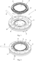
- the device 10 is used for the sterile transfer of goods between a container (not shown) and an isolator (not shown).
- the goods can be, for example, rubber or plastic stoppers for infusion bottles or vials, syringe parts, or even liquids.
- Fig. 1 the US 9 704 607 B2 and the corresponding description.
- the device 10 For sterile material transfer, the device 10 comprises a so-called alpha part 12 or alpha port on the isolator side, while it comprises a so-called beta part 14 or beta port on the container side.
- the alpha part 12 has a port opening surrounded by a port flange 16, also referred to as an alpha flange, a port door 18 for closing the port opening, and an actuating mechanism 20 for opening and closing the port door 18.
- the beta part has a container opening surrounded by a container flange 22, also referred to as a beta flange, and a container lid 24, which normally closes the container opening and can be removed from the container flange 22.
- the beta part 14 of the container is docked to the alpha part 12 of the isolator.
- bayonet connections that tightly connect the container flange 22 to the port flange 16 and the container lid 24 to the port door 18, while simultaneously the container lid 24 detaches from the container flange 22.
- One bayonet connection has cams 26 projecting radially beyond the container flange 22, which, upon docking, engage with a corresponding receiving groove 28 of the port flange 16.
- the inner part of the port flange 16 is rotated by means of a lever 30 about an axis perpendicular to the plane of the port opening until the cams 26 abut against corresponding cam stops in the groove 28.
- Beta Part 14 can also be docked to the Alpha Part 12 by rotating the Beta Part 14 relative to the Alpha Part 12.
- the port door 18 is pivotally mounted on the port flange 16 so that, after the container has been docked, it can be pivoted into the interior of the isolator together with its lid 24.
- the port door 18 is provided with a bracket 32 rigidly mounted on the port door 18, which extends diametrically across the inside of the port door 18.
- a first end of the bracket 32, which projects radially beyond the circumference of the port door 18, is pivotally connected to the inside of the port flange 16 by means of a pivot joint 34.
- the port door 18 can be locked in its closed position by means of the actuating mechanism 20, which for this purpose comprises a lock 36.
- the lock 36 comprises a first lock part 38, which is rotatably mounted on a second projecting end of the bracket 32, by means of an actuating handle 40 between a closed position ( Fig. 3 ) and an open position ( Fig. 4 ) and has a radially projecting locking lug 42.
- the lock 36 further comprises a second lock part 44, which is rigidly mounted on the inside of the port flange 16 opposite the first lock part 38 and has a bolt receptacle 46 ( Fig. 20 ) into which the locking lug 42 engages in the closed position to keep the port door 18 closed. In the open position, the locking lug 42 is disengaged from the latch receptacle 46.
- the rotatable lock part 38 has a disc-shaped configuration and is penetrated by a rigid axle (not visible) that projects vertically above the shackle 32.
- a disc-shaped cover 48 is snapped onto the lock part 38 and rotates together with the lock part 38.
- the device 10 comprises four safety devices 50, 52, 54 arranged in the alpha part 12, which are intended to prevent incorrect operation of the Rapid Transfer Port, which could cause contamination of the goods through unwanted contact with the environment or contamination of the isolator through unwanted entry of germs during the transfer of goods.
- the first safety device prevents the port door 18 from opening if the container is not provided with a container lid 24 and therefore the interior of the container is not sterile.
- the second safety device 50 prevents the rotatable lock part 38 from moving into the open position and thus the port door 18 from opening as long as the container flange 14 is not properly docked to the port flange 12.
- the third Safety device 52 blocks the container flange 14, which is properly connected to the port flange 12, and prevents the associated bayonet connection from becoming loose as soon as the rotatable lock part 38 leaves the closed position toward the open position.
- the fourth safety device 54 prevents the lock part 38 from turning back to the closed position when the port door 18 is open, thus also preventing the release of the second and third safety devices 50, 52.
- the three safety devices 50, 52, 54 each comprise two magnetic elements 56, 58; 60, 62; 64, 66 which are movable relative to one another, wherein two closed walls 68, 70 without a through opening are arranged between the two magnetic elements 56, 58; 60, 62; 64, 66 and wherein the magnetic elements 56, 58; 60, 62; 64, 66 attract or repel one another through the closed walls 68, 70 either in a blocking position or in a release position of the respective safety device 50, 52, 54.
- both magnetic elements 56, 58; 60, 62; 64, 66 each comprise a cylindrical or annular magnetic body made of a permanent magnetic material, for example, a neodymium-iron-boron alloy or another rare earth alloy.
- the two magnetic bodies are each mounted such that two flat end faces of the magnetic bodies face each other.
- the first safety device used to check the presence of the container lid 24 is different from the Rapid Transfer Port described here from the US 9 704 607 B2 only with a statically stressed seal in the port door 18. Therefore, and to avoid having to equip each container lid with a magnetic element, it is designed here without magnetic elements and will not be described in detail.
- the above-mentioned second, third, and fourth safety devices 50, 52, 54 each comprise two magnetic elements 56, 58; 60, 62; 64, 66.
- the first magnetic element 56 mounted in the port flange 16 consists of an annular magnetic body and a holder 72, which are movable in a blind hole of the port flange 16 against the force of a return spring 74.
- the holder 72 comprises a plate and a pin that penetrates the annular magnetic body.
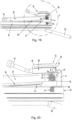
- a pawl 76 pivotally mounted in the port flange 16 near the blind hole acts on the plate. The pawl 76 projects into the receiving groove 28 of the port flange 16 before the container is docked, as shown in Fig. 13 where it is fully depressed by one of the cams 26 of the container flange 22, as in Fig.
- the latch 76 is moved back into the receiving groove 28 by the return spring 74, as shown in Fig. 13
- the first magnetic element 56 is moved back and forth between two end positions, as shown in Fig. 6 and 8 shown.
- the pawl 76 projects into the receiving groove 28
- the first magnetic element 56 is in the first end position ( Fig. 6 )
- the latch 76 is depressed, it is in the second end position at the bottom of the blind hole ( Fig. 8 ).
- the blind hole is closed towards the bracket 32 by the wall 68, which consists of thin non-rusting and non-magnetic steel sheet.
- the second magnetic element 58 is located opposite the first magnetic element 56 inside the bracket 32.
- the second magnetic element 58 includes a pin 78 that projects beyond the side of the magnetic body facing away from the port flange 16.
- the magnetic body and the pin 78 are movable in a blind hole in the bracket 32, which is closed off from the port flange by the wall 70.
- the wall 70 is also made of thin, stainless and non-magnetic sheet steel.
- the pin 78 rests with its end facing away from the magnet body against another pin 80, which is mounted axially displaceably in a bore of the rotatable lock part 38 against the force of a return spring 82.
- the return spring 82 presses the second magnet element 58 against the wall 70 via the pins 80, 78 when the first magnet element 56 is in its first end position with the latch 76 unloaded.
- the two magnetic bodies are aligned so that they repel each other.
- the pawl 76 is pressed down, thereby moving the first magnetic element 56 into the second end position and bringing it closer to the second magnetic element 58, the second magnetic element 58 is lifted from the bottom of the blind hole against the force of the spring 82.
- the repulsive forces of the two magnetic elements 56, 58 are matched to the spring force of the return spring 82 in such a way that the mutually abutting flat end surfaces of the two pins 78, 80 are aligned with a flat contact surface of the rotatable lock part 38 on the shackle 32 when the pawl 76 is fully pressed down.
- This Fig. 8 The position shown is the release position of the second safety device 50, in which the rotatable lock part 38 can be rotated from the closed position of the lock 36 into its open position.
- the second safety device 50 assumes the blocking position in which the rotatable lock part 38 cannot be moved out of the closed position.
- the first magnetic element 60 mounted in the port flange 16 has a corresponding design to that of the second safety device 50 and consists of an annular magnetic body and a holder 84, which are movable in a blind hole in the port flange 16 against the force of a return spring 86.
- the holder 84 consists of a plate and two pins, one of which penetrates the annular magnetic body. The other pin projects beyond the opposite side of the plate.
- the magnetic body and the two pins are axially movable in the blind hole, which is closed off from the bracket 32 by the wall 68.
- the second magnetic element 62 consists of a long cylindrical magnetic body which is connected in a rotationally fixed manner to the rotatable lock part 38, projects beyond the side of the lock part 38 facing the port flange 16 and projects into a curved slot 90 of the bracket 32, which is closed at its base towards the port flange 16 by the wall 70.
- the second magnetic element 62 is arranged exactly opposite the first magnetic element 60.
- the second magnetic element 62 is laterally offset with respect to the first magnetic element 60.
- the two magnetic bodies are aligned such that they attract each other when, in the closed position of the lock 36, the second magnetic element 62 is located opposite the first magnetic element 60.
- the attractive forces of the two magnetic elements 60, 62 are matched to the spring force of the return spring 86 such that, in this release position of the third safety device 52, the first magnetic element 60 assumes a first end position in which the pin 88 is completely retracted from the receiving groove 28 against the force of the return spring 86 ( Fig. 13 ).
- the magnetic attraction forces between the magnetic elements 60, 62 decrease to such an extent that the first magnetic element 60 is pressed by the return spring 86 back into the second end position, in which the pin 88 again projects into the receiving groove 28 ( Fig. 14 ) and the third safety device 52 is in its blocking position.
- the position of the pin 88 in the groove 28 is selected such that it projects into the groove 28 directly behind one of the cams 26 of the container flange 22 and prevents the cam 26 or the container flange 22 from turning back.
- the first magnetic element 64 consists merely of a stationary magnetic body mounted in the port flange 16, which is separated from the interior of the insulator by the wall 68 on the inside of the port flange 16.
- the second magnetic element 66 is located directly opposite the first magnetic element 64 inside the bracket 32, so that when the port door 18 is opened, it moves away from the first magnetic element 64 and, when the port door 18 is closed, it moves closer to the first magnetic element 64.
- the second magnetic element 66 comprises a pin 92 that projects beyond the side of the magnetic body facing away from the port flange 16.
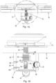
- the magnetic body and the pin 92 are axially movable in a blind hole in the bracket 32, which is closed off from the port flange 16 by the wall 70. As best shown in Fig. 16 and 18 As shown, the pin 92 rests with its flat end facing away from the magnet body against the flat end of a further pin 94 which is mounted so as to be axially displaceable in a blind hole of the rotatable lock part 38 against the force of a return spring 96.
- the two magnetic bodies are aligned such that they repel each other when the port door 18 is closed, thus bringing the second magnetic element 66 closer to the first magnetic element 64.
- the repulsive forces of the two magnetic elements 64, 66 are matched to the spring force of the return spring 96 such that the mutually abutting flat end faces of the two pins 92, 94 are aligned with the flat contact surface of the rotatable lock part 38 on the shackle 32 when the shackle 32 rests against the port flange 16 with the port door 18 closed.
- This position is the release position of the fourth safety device 54, in which the rotatable lock part 38 can be rotated from the open position of the lock 36 back into the closed position.
- the rotatable lock part 38 is sealed to the shackle 32 and to the cover 48 by an O-ring 98, 100 which extends along the outer circumference of the rotatable lock part 38 and the cover 48, respectively.
Landscapes
- Engineering & Computer Science (AREA)
- Mechanical Engineering (AREA)
- General Engineering & Computer Science (AREA)
- Health & Medical Sciences (AREA)
- Chemical & Material Sciences (AREA)
- Chemical Kinetics & Catalysis (AREA)
- Clinical Laboratory Science (AREA)
- General Health & Medical Sciences (AREA)
- Hematology (AREA)
- Analytical Chemistry (AREA)
- Closures For Containers (AREA)
- Devices For Use In Laboratory Experiments (AREA)
- Apparatus For Disinfection Or Sterilisation (AREA)
- Pressure Vessels And Lids Thereof (AREA)
Claims (14)
- Dispositif (10) pour le transfert stérile de produits entre un récipient et un isolateur, le récipient présentant une ouverture de récipient entourée par une bride de récipient (22) et un couvercle de récipient (24) détachable de la bride de récipient (22) pour fermer l'ouverture de récipient, l'isolateur présentant une ouverture de port entourée par une bride de port (16), une porte de port (18) pour fermer l'ouverture de port et un mécanisme d'actionnement (20) mobile entre une position de fermeture et une position d'ouverture pour ouvrir et fermer la porte de port (18), la bride de récipient (22) pouvant être reliée de manière amovible à la bride de port (16) et le couvercle de récipient (24) pouvant être relié de manière amovible à la porte de port (18), ainsi qu'à un ou plusieurs des appareils de sécurité suivants (50, 52, 54) :- un premier appareil de sécurité qui bloque le mécanisme d'actionnement (20) dans la position de fermeture et le libère lorsque la porte de port (18) est en appui contre le couvercle de récipient (24),- un deuxième appareil de sécurité (50) qui bloque le mécanisme d'actionnement (20) dans la position de fermeture et le libère lorsque la bride de récipient (22) est correctement reliée à la bride de port (16),- un troisième appareil de sécurité (52) qui bloque la bride de récipient (22) reliée à la bride de port (16) lorsque le mécanisme d'actionnement (20) quitte la position de fermeture, et qui empêche le détachement des deux brides (16, 22) l'une de l'autre tant que la porte de port (18) est ouverte,- un quatrième appareil de sécurité (54) qui bloque un retour du mécanisme d'actionnement (20) de la position d'ouverture à la position de fermeture lorsque la porte de port (18) est ouverte, et- un cinquième appareil de sécurité qui bloque le mécanisme d'actionnement (20) lorsque la bride de récipient (22) n'est pas correctement reliée à la bride de port (16) entre la libération du mécanisme d'actionnement (20) par le deuxième appareil de sécurité (50) et le blocage de la bride de récipient (22) par le troisième appareil de sécurité (52), caractérisé en ce qu'au moins l'un des appareils de sécurité (50 ; 52 ; 54) comprend deux éléments magnétiques (56, 58 ; 60, 62 ; 64, 66) qui sont mobiles l'un par rapport à l'autre, en ce qu'entre les deux éléments magnétiques (56, 58 ; 60, 62 ; 64, 66) est agencée au moins une paroi fermée (68, 70) sans ouverture de passage et en ce que les éléments magnétiques (56, 58 ; 60, 62 ; 64, 66) s'attirent ou se repoussent mutuellement soit dans une position de blocage soit dans une position de libération de l'appareil de sécurité (50 ; 52 ; 54) à travers la paroi fermée (68, 70).
- Dispositif selon la revendication 1, caractérisé en ce que les deux éléments magnétiques (56, 58 ; 60, 62 ; 64, 66) sont agencés dans deux composants (32 ; 16) du dispositif séparés par l'au moins une paroi (68, 70) et mobiles l'un par rapport à l'autre.
- Dispositif selon la revendication 1 ou 2, caractérisé en ce que chacun des deux éléments magnétiques (56, 58 ; 60, 62 ; 64, 66) comprend au moins un corps magnétique permanent.
- Dispositif selon la revendication 1 ou 2, caractérisé en ce que l'un des deux éléments magnétiques comprend au moins un corps ferromagnétique et l'autre des deux éléments magnétiques comprend au moins un corps magnétique permanent.
- Dispositif selon l'une quelconque des revendications précédentes, caractérisé en ce qu'au moins l'un des deux éléments magnétiques (56, 58 ; 60, 62 ; 64, 66) est mobile entre deux positions d'extrémité.
- Dispositif selon la revendication 5, caractérisé en ce que l'au moins un élément magnétique mobile (56, 58 ; 60 ; 66) est mobile à l'encontre de la force de ressort d'un ressort de rappel (74, 82 ; 86 ; 96).
- Dispositif selon l'une quelconque des revendications précédentes, caractérisé en ce que le mécanisme d'actionnement (20) comprend une serrure (36) avec une partie de serrure (38) rotative autour d'un axe de rotation entre la position de fermeture et la position d'ouverture, et en ce qu'au moins l'un des deux éléments magnétiques (56, 58 ; 60 ; 66) est mobile parallèlement à l'axe de rotation de la partie de serrure (36).
- Dispositif selon la revendication 7, caractérisé en ce que l'élément magnétique mobile (58 ; 66) bloque une rotation de la partie de serrure (38) dans la position de blocage de la serrure (36) et autorise une rotation de la partie de serrure (38) dans la position de libération.
- Dispositif selon l'une quelconque des revendications précédentes, caractérisé en ce que le mécanisme d'actionnement (20) comprend une serrure (36) avec une partie de serrure (38) rotative autour d'un axe de rotation entre la position de fermeture et la position d'ouverture, et en ce que l'un des deux éléments magnétiques (62) est rotatif conjointement avec la partie de serrure (38) autour de l'axe de rotation.
- Dispositif selon l'une quelconque des revendications précédentes, caractérisé en ce que les deux éléments magnétiques (56, 58 ; 60, 62 ; 64, 66) comprennent chacun un premier élément magnétique (56 ; 60 ; 64) agencé dans la bride de port (16).
- Dispositif selon la revendication 10, caractérisé en ce que le premier élément magnétique (56 ; 60) est mobile dans la bride de port (16).
- Dispositif selon la revendication 10 ou 11, caractérisé en ce que les deux éléments magnétiques (56, 58) du deuxième appareil de sécurité (50) comprennent un deuxième élément magnétique (58) qui libère le mécanisme d'actionnement (20) dans la position de fermeture lorsque, lors de la liaison de la bride de récipient (22) à la bride de port (16), le premier élément magnétique (56) est rapproché du deuxième élément magnétique (58).
- Dispositif selon la revendication 10 ou 11, caractérisé en ce que les deux éléments magnétiques (60 ; 62) du troisième appareil de sécurité (52) comprennent un deuxième élément magnétique (62) qui s'éloigne du premier élément magnétique (60) lors du déplacement du mécanisme d'actionnement (20) vers la position d'ouverture, après quoi le premier élément magnétique (60) bloque la bride de récipient (22) reliée à la bride de port (16).
- Dispositif selon la revendication 10 ou 11, caractérisé en ce que les deux éléments magnétiques (64 ; 66) du quatrième appareil de sécurité (54) comprennent un deuxième élément magnétique (66) mobile conjointement avec la porte de port (18), qui bloque le mécanisme d'actionnement (20) dans la position d'ouverture lorsque le deuxième élément magnétique (66) s'éloigne du premier élément magnétique (64) lors de l'ouverture de la porte de port (18).
Applications Claiming Priority (2)
| Application Number | Priority Date | Filing Date | Title |
|---|---|---|---|
| DE102019003317.5A DE102019003317A1 (de) | 2019-05-10 | 2019-05-10 | Vorrichtung zur sterilen Übergabe von Gut zwischen einem Behälter und einem Isolator |
| PCT/EP2020/060234 WO2020229067A1 (fr) | 2019-05-10 | 2020-04-09 | Dispositif de transfert stérile de produit entre un récipient et un isolateur |
Publications (2)
| Publication Number | Publication Date |
|---|---|
| EP3966476A1 EP3966476A1 (fr) | 2022-03-16 |
| EP3966476B1 true EP3966476B1 (fr) | 2025-06-11 |
Family
ID=70416438
Family Applications (1)
| Application Number | Title | Priority Date | Filing Date |
|---|---|---|---|
| EP20720908.1A Active EP3966476B1 (fr) | 2019-05-10 | 2020-04-09 | Dispositif de transfert stérile de produit entre un récipient et un isolateur |
Country Status (6)
| Country | Link |
|---|---|
| US (1) | US11883815B2 (fr) |
| EP (1) | EP3966476B1 (fr) |
| JP (1) | JP7504480B2 (fr) |
| KR (1) | KR102785922B1 (fr) |
| DE (1) | DE102019003317A1 (fr) |
| WO (1) | WO2020229067A1 (fr) |
Families Citing this family (11)
| Publication number | Priority date | Publication date | Assignee | Title |
|---|---|---|---|---|
| DE102019003317A1 (de) * | 2019-05-10 | 2020-11-12 | Atec Pharmatechnik Gmbh | Vorrichtung zur sterilen Übergabe von Gut zwischen einem Behälter und einem Isolator |
| FR3117464B1 (fr) * | 2020-12-10 | 2023-04-14 | Getinge La Calhene | Ensemble de connexion pour conteneur de transfert etanche |
| DE102020215620A1 (de) * | 2020-12-10 | 2022-06-15 | Castus GmbH & Co. KG | Türvorrichtung zum Anschließen eines Behälters an einen Isolierraum |
| JP1723868S (ja) * | 2021-12-23 | 2022-09-02 | 移送ドア | |
| DE102022101774A1 (de) | 2022-01-26 | 2023-07-27 | Atec Pharmatechnik Gmbh | Aufnahme-Port zum Übertragen von Gegenständen in einen Behälter sowie Rapid-Transfer-System mit einem Aufnahme-Port |
| DE102022131808A1 (de) * | 2022-11-30 | 2024-06-06 | Groninger & Co. Gmbh | Funktionselement, Beta-Behältersystem, Transfersystem und Barrieresystem |
| USD1098480S1 (en) * | 2023-04-26 | 2025-10-14 | Stabilus Motion Controls Gmbh | Handle for a rapid transfer port |
| USD1098481S1 (en) * | 2023-04-26 | 2025-10-14 | Stabilus Motion Controls Gmbh | Handle for a rapid transfer port |
| DE102024102062A1 (de) * | 2024-01-24 | 2025-07-24 | Peter Schubert | Transferportanordnung zum Transfer von Komponenten in und/oder aus einem pharmazeutischen Isolator |
| FR3164985A1 (fr) * | 2024-07-24 | 2026-01-30 | Getinge Life Science France | Ensemble de connexion pour cellule de transfert étanche comportant une bride portant au moins un levier à indexation magnétique |
| KR102744699B1 (ko) * | 2024-08-02 | 2024-12-19 | 바이온팩 주식회사 | 이송장치 |
Citations (2)
| Publication number | Priority date | Publication date | Assignee | Title |
|---|---|---|---|---|
| US6315013B1 (en) * | 1999-08-27 | 2001-11-13 | Salvatore Lardieri | System for ensuring permanent conditions of sterility of the product contained inside a structure that is being connected to another structure for transfer |
| US20030126799A1 (en) * | 1998-12-11 | 2003-07-10 | Jean-Yves Porret | Device for connecting doors between two chambers isolated from the external medium |
Family Cites Families (12)
| Publication number | Priority date | Publication date | Assignee | Title |
|---|---|---|---|---|
| FR2496325B1 (fr) * | 1980-12-16 | 1987-05-22 | Calhene | Dispositif de securite pour systeme de verrouillage entre deux enceintes etanches |
| FR2695343B1 (fr) * | 1992-09-04 | 1994-11-25 | Sne Calhene | Mécanisme de commande centralisé, à sécurités incorporées, pour un dispositif de transfert étanche entre deux volumes clos. |
| US5425400A (en) * | 1993-03-29 | 1995-06-20 | Lee A. Francis | Transfer port apparatus and method |
| FR2721289B1 (fr) * | 1994-06-17 | 1996-08-30 | Idc Isolateur Denominateur | Dispositif de jonction étanche entre deux enceintes isolées d'un milieu extérieur. |
| EP2362968B1 (fr) * | 2008-11-05 | 2016-01-27 | West Pharmaceutical Services, Inc. | Dispositif d'obturation d'une ouverture mettant en communication deux enceintes isolées de l'environnement extérieur |
| US20120153610A1 (en) * | 2010-12-20 | 2012-06-21 | Thomas Mitchel Young | Aseptic transfer port |
| FR2978363B1 (fr) * | 2011-07-29 | 2013-09-13 | Sartorius Stedim Aseptics | Conteneur pour le transfert aseptique d'un produit biopharmaceutique. |
| FR2981386B1 (fr) | 2011-10-14 | 2014-08-22 | Getinge La Calhene | Mecanisme de commande a haut niveau de securite pour un dispositif de transfert etanche entre deux volumes clos |
| FR3010119A1 (fr) | 2013-09-03 | 2015-03-06 | Getinge La Calhene | Dispositif de connexion etanche a securite de fonctionnement amelioree |
| FR3010118B1 (fr) * | 2013-09-03 | 2016-02-26 | Getinge La Calhene | Enceinte etanche comportant un mecanisme de commande d'ouverture et de fermeture pour un dispositif de connexion etanche entre deux volumes clos |
| FR3071725A1 (fr) * | 2017-10-03 | 2019-04-05 | Sartorius Stedim Fmt Sas | Dispositif de jonction etanche pour le transfert aseptique d’un produit biopharmaceutique entre une enceinte et un conteneur |
| DE102019003317A1 (de) * | 2019-05-10 | 2020-11-12 | Atec Pharmatechnik Gmbh | Vorrichtung zur sterilen Übergabe von Gut zwischen einem Behälter und einem Isolator |
-
2019
- 2019-05-10 DE DE102019003317.5A patent/DE102019003317A1/de active Pending
-
2020
- 2020-04-09 WO PCT/EP2020/060234 patent/WO2020229067A1/fr not_active Ceased
- 2020-04-09 EP EP20720908.1A patent/EP3966476B1/fr active Active
- 2020-04-09 KR KR1020217037348A patent/KR102785922B1/ko active Active
- 2020-04-09 US US17/609,412 patent/US11883815B2/en active Active
- 2020-04-09 JP JP2021566223A patent/JP7504480B2/ja active Active
Patent Citations (2)
| Publication number | Priority date | Publication date | Assignee | Title |
|---|---|---|---|---|
| US20030126799A1 (en) * | 1998-12-11 | 2003-07-10 | Jean-Yves Porret | Device for connecting doors between two chambers isolated from the external medium |
| US6315013B1 (en) * | 1999-08-27 | 2001-11-13 | Salvatore Lardieri | System for ensuring permanent conditions of sterility of the product contained inside a structure that is being connected to another structure for transfer |
Also Published As
| Publication number | Publication date |
|---|---|
| EP3966476A1 (fr) | 2022-03-16 |
| JP7504480B2 (ja) | 2024-06-24 |
| WO2020229067A1 (fr) | 2020-11-19 |
| US11883815B2 (en) | 2024-01-30 |
| DE102019003317A1 (de) | 2020-11-12 |
| US20220250050A1 (en) | 2022-08-11 |
| KR20220007067A (ko) | 2022-01-18 |
| JP2022536826A (ja) | 2022-08-19 |
| KR102785922B1 (ko) | 2025-03-25 |
Similar Documents
| Publication | Publication Date | Title |
|---|---|---|
| WO2020229067A1 (fr) | Dispositif de transfert stérile de produit entre un récipient et un isolateur | |
| EP2497744B1 (fr) | Outil de fermeture | |
| DE69307433T2 (de) | Zentralisierter Steuermechanismus mit eingebauten Sicherheiten zur Verwendung in einer abgedichteten Übertragungseinrichtung zwischen zwei geschlossenen Räumen | |
| DE4342962C1 (de) | Vorrichtung zum Kuppeln von Behältnissen | |
| EP3132854A1 (fr) | Rotor d'une centrifugeuse | |
| WO2017182453A1 (fr) | Tête de dispositif de fermeture servant à fermer un contenant doté d'une fermeture | |
| EP0285857A1 (fr) | Dispositif de fermeture pour une porte d'armoire à équipement électrique | |
| EP2443054B1 (fr) | Dispositif à double clapet pour jonction, sans nuisance pour l'environnement, de deux récipients | |
| DE102008049129A1 (de) | Kupplungsverschluss sowie Befestigungsmodul und Andockeinrichtung, jeweils enthaltend diesen Kupplungsverschluss | |
| EP3524365A2 (fr) | Système d'amarrage | |
| DE102008010272A1 (de) | Deckelverschluss für Gehäusedeckel von Laborgeräten und dergleichen | |
| DE60009404T2 (de) | System für einen sterilen transfer eines produktes zwischen zwei behältern | |
| EP3268299A1 (fr) | Dispositif d'accouplement et procédé d'accouplement | |
| DE102016004200A1 (de) | Rapid-Transfer-Port mit linear beweglicher und schwenkbarer Porttür | |
| EP2116306A1 (fr) | Fermeture pour un récipient destiné à la réception d'échantillons liquides et récipient en étant équipé | |
| EP2193092B1 (fr) | Dispositif d'adossement comprenant deux fermetures de couplage pour le transfert, isolé de l'environnement, de matière en vrac, renfermant au moins une unité de verrouillage | |
| DE3512848A1 (de) | Zentrifuge | |
| WO2019233892A1 (fr) | Système de fermeture, unité filtrante pour un système de barrière, et système de barrière, en particulier isolateur | |
| DE112011103530T5 (de) | Betätigter Absperrschieber mit verstärkter Dichtigkeit | |
| WO2007003283A1 (fr) | Recipient d'echantillonnage, notamment bouteille d'echantillonnage pour le lait, et procede d'echantillonnage, notamment pour echantillonner du lait | |
| EP3444210B1 (fr) | Dispositif de connexion pour raccorder un premier conteneur flexible à un second conteneur de dimensions stables | |
| EP2128031B1 (fr) | Dispositif de liaison et de fermeture de récipients | |
| DE8509450U1 (de) | Vorrichtung zum Öffnen und Schließen einer Schiebetür | |
| DE102013110292B4 (de) | Vorrichtung zum Koppeln von zwei Behältern | |
| DE102018202896A1 (de) | Probenahmevorrichtung für die mobile Manipulation |
Legal Events
| Date | Code | Title | Description |
|---|---|---|---|
| STAA | Information on the status of an ep patent application or granted ep patent |
Free format text: STATUS: UNKNOWN |
|
| STAA | Information on the status of an ep patent application or granted ep patent |
Free format text: STATUS: THE INTERNATIONAL PUBLICATION HAS BEEN MADE |
|
| PUAI | Public reference made under article 153(3) epc to a published international application that has entered the european phase |
Free format text: ORIGINAL CODE: 0009012 |
|
| STAA | Information on the status of an ep patent application or granted ep patent |
Free format text: STATUS: REQUEST FOR EXAMINATION WAS MADE |
|
| 17P | Request for examination filed |
Effective date: 20211210 |
|
| AK | Designated contracting states |
Kind code of ref document: A1 Designated state(s): AL AT BE BG CH CY CZ DE DK EE ES FI FR GB GR HR HU IE IS IT LI LT LU LV MC MK MT NL NO PL PT RO RS SE SI SK SM TR |
|
| DAV | Request for validation of the european patent (deleted) | ||
| DAX | Request for extension of the european patent (deleted) | ||
| STAA | Information on the status of an ep patent application or granted ep patent |
Free format text: STATUS: EXAMINATION IS IN PROGRESS |
|
| 17Q | First examination report despatched |
Effective date: 20220908 |
|
| GRAP | Despatch of communication of intention to grant a patent |
Free format text: ORIGINAL CODE: EPIDOSNIGR1 |
|
| STAA | Information on the status of an ep patent application or granted ep patent |
Free format text: STATUS: GRANT OF PATENT IS INTENDED |
|
| RIC1 | Information provided on ipc code assigned before grant |
Ipc: F16J 13/24 20060101ALI20250206BHEP Ipc: B01L 1/02 20060101ALI20250206BHEP Ipc: B01L 3/00 20060101ALI20250206BHEP Ipc: B65D 45/02 20060101ALI20250206BHEP Ipc: G21F 7/005 20060101ALI20250206BHEP Ipc: F16J 13/02 20060101AFI20250206BHEP |
|
| INTG | Intention to grant announced |
Effective date: 20250217 |
|
| GRAS | Grant fee paid |
Free format text: ORIGINAL CODE: EPIDOSNIGR3 |
|
| GRAA | (expected) grant |
Free format text: ORIGINAL CODE: 0009210 |
|
| STAA | Information on the status of an ep patent application or granted ep patent |
Free format text: STATUS: THE PATENT HAS BEEN GRANTED |
|
| AK | Designated contracting states |
Kind code of ref document: B1 Designated state(s): AL AT BE BG CH CY CZ DE DK EE ES FI FR GB GR HR HU IE IS IT LI LT LU LV MC MK MT NL NO PL PT RO RS SE SI SK SM TR |
|
| REG | Reference to a national code |
Ref country code: GB Ref legal event code: FG4D Free format text: NOT ENGLISH |
|
| REG | Reference to a national code |
Ref country code: CH Ref legal event code: EP |
|
| REG | Reference to a national code |
Ref country code: DE Ref legal event code: R096 Ref document number: 502020011200 Country of ref document: DE |
|
| REG | Reference to a national code |
Ref country code: IE Ref legal event code: FG4D Free format text: LANGUAGE OF EP DOCUMENT: GERMAN |
|
| P01 | Opt-out of the competence of the unified patent court (upc) registered |
Free format text: CASE NUMBER: UPC_APP_1440_3966476/2025 Effective date: 20250730 |
|
| REG | Reference to a national code |
Ref country code: SE Ref legal event code: TRGR |
|
| PG25 | Lapsed in a contracting state [announced via postgrant information from national office to epo] |
Ref country code: ES Free format text: LAPSE BECAUSE OF FAILURE TO SUBMIT A TRANSLATION OF THE DESCRIPTION OR TO PAY THE FEE WITHIN THE PRESCRIBED TIME-LIMIT Effective date: 20250611 Ref country code: FI Free format text: LAPSE BECAUSE OF FAILURE TO SUBMIT A TRANSLATION OF THE DESCRIPTION OR TO PAY THE FEE WITHIN THE PRESCRIBED TIME-LIMIT Effective date: 20250611 |
|
| REG | Reference to a national code |
Ref country code: LT Ref legal event code: MG9D |
|
| PG25 | Lapsed in a contracting state [announced via postgrant information from national office to epo] |
Ref country code: GR Free format text: LAPSE BECAUSE OF FAILURE TO SUBMIT A TRANSLATION OF THE DESCRIPTION OR TO PAY THE FEE WITHIN THE PRESCRIBED TIME-LIMIT Effective date: 20250912 Ref country code: NO Free format text: LAPSE BECAUSE OF FAILURE TO SUBMIT A TRANSLATION OF THE DESCRIPTION OR TO PAY THE FEE WITHIN THE PRESCRIBED TIME-LIMIT Effective date: 20250911 |
|
| REG | Reference to a national code |
Ref country code: NL Ref legal event code: MP Effective date: 20250611 |
|
| PG25 | Lapsed in a contracting state [announced via postgrant information from national office to epo] |
Ref country code: BG Free format text: LAPSE BECAUSE OF FAILURE TO SUBMIT A TRANSLATION OF THE DESCRIPTION OR TO PAY THE FEE WITHIN THE PRESCRIBED TIME-LIMIT Effective date: 20250611 |
|
| PG25 | Lapsed in a contracting state [announced via postgrant information from national office to epo] |
Ref country code: HR Free format text: LAPSE BECAUSE OF FAILURE TO SUBMIT A TRANSLATION OF THE DESCRIPTION OR TO PAY THE FEE WITHIN THE PRESCRIBED TIME-LIMIT Effective date: 20250611 |
|
| PG25 | Lapsed in a contracting state [announced via postgrant information from national office to epo] |
Ref country code: RS Free format text: LAPSE BECAUSE OF FAILURE TO SUBMIT A TRANSLATION OF THE DESCRIPTION OR TO PAY THE FEE WITHIN THE PRESCRIBED TIME-LIMIT Effective date: 20250911 |
|
| PG25 | Lapsed in a contracting state [announced via postgrant information from national office to epo] |
Ref country code: LV Free format text: LAPSE BECAUSE OF FAILURE TO SUBMIT A TRANSLATION OF THE DESCRIPTION OR TO PAY THE FEE WITHIN THE PRESCRIBED TIME-LIMIT Effective date: 20250611 |
|
| PG25 | Lapsed in a contracting state [announced via postgrant information from national office to epo] |
Ref country code: NL Free format text: LAPSE BECAUSE OF FAILURE TO SUBMIT A TRANSLATION OF THE DESCRIPTION OR TO PAY THE FEE WITHIN THE PRESCRIBED TIME-LIMIT Effective date: 20250611 |
|
| PG25 | Lapsed in a contracting state [announced via postgrant information from national office to epo] |
Ref country code: PT Free format text: LAPSE BECAUSE OF FAILURE TO SUBMIT A TRANSLATION OF THE DESCRIPTION OR TO PAY THE FEE WITHIN THE PRESCRIBED TIME-LIMIT Effective date: 20251013 |
|
| PG25 | Lapsed in a contracting state [announced via postgrant information from national office to epo] |
Ref country code: IS Free format text: LAPSE BECAUSE OF FAILURE TO SUBMIT A TRANSLATION OF THE DESCRIPTION OR TO PAY THE FEE WITHIN THE PRESCRIBED TIME-LIMIT Effective date: 20251011 |
|
| PG25 | Lapsed in a contracting state [announced via postgrant information from national office to epo] |
Ref country code: SM Free format text: LAPSE BECAUSE OF FAILURE TO SUBMIT A TRANSLATION OF THE DESCRIPTION OR TO PAY THE FEE WITHIN THE PRESCRIBED TIME-LIMIT Effective date: 20250611 |
|
| PG25 | Lapsed in a contracting state [announced via postgrant information from national office to epo] |
Ref country code: CZ Free format text: LAPSE BECAUSE OF FAILURE TO SUBMIT A TRANSLATION OF THE DESCRIPTION OR TO PAY THE FEE WITHIN THE PRESCRIBED TIME-LIMIT Effective date: 20250611 |
|
| PG25 | Lapsed in a contracting state [announced via postgrant information from national office to epo] |
Ref country code: PL Free format text: LAPSE BECAUSE OF FAILURE TO SUBMIT A TRANSLATION OF THE DESCRIPTION OR TO PAY THE FEE WITHIN THE PRESCRIBED TIME-LIMIT Effective date: 20250611 |
|
| PG25 | Lapsed in a contracting state [announced via postgrant information from national office to epo] |
Ref country code: EE Free format text: LAPSE BECAUSE OF FAILURE TO SUBMIT A TRANSLATION OF THE DESCRIPTION OR TO PAY THE FEE WITHIN THE PRESCRIBED TIME-LIMIT Effective date: 20250611 |
|
| PG25 | Lapsed in a contracting state [announced via postgrant information from national office to epo] |
Ref country code: RO Free format text: LAPSE BECAUSE OF FAILURE TO SUBMIT A TRANSLATION OF THE DESCRIPTION OR TO PAY THE FEE WITHIN THE PRESCRIBED TIME-LIMIT Effective date: 20250611 Ref country code: SK Free format text: LAPSE BECAUSE OF FAILURE TO SUBMIT A TRANSLATION OF THE DESCRIPTION OR TO PAY THE FEE WITHIN THE PRESCRIBED TIME-LIMIT Effective date: 20250611 |
|
| REG | Reference to a national code |
Ref country code: DE Ref legal event code: R097 Ref document number: 502020011200 Country of ref document: DE |
|
| PG25 | Lapsed in a contracting state [announced via postgrant information from national office to epo] |
Ref country code: DK Free format text: LAPSE BECAUSE OF FAILURE TO SUBMIT A TRANSLATION OF THE DESCRIPTION OR TO PAY THE FEE WITHIN THE PRESCRIBED TIME-LIMIT Effective date: 20250611 |
|
| PG25 | Lapsed in a contracting state [announced via postgrant information from national office to epo] |
Ref country code: IT Free format text: LAPSE BECAUSE OF FAILURE TO SUBMIT A TRANSLATION OF THE DESCRIPTION OR TO PAY THE FEE WITHIN THE PRESCRIBED TIME-LIMIT Effective date: 20250611 |
|
| PLBE | No opposition filed within time limit |
Free format text: ORIGINAL CODE: 0009261 |
|
| STAA | Information on the status of an ep patent application or granted ep patent |
Free format text: STATUS: NO OPPOSITION FILED WITHIN TIME LIMIT |
|
| REG | Reference to a national code |
Ref country code: CH Ref legal event code: L10 Free format text: ST27 STATUS EVENT CODE: U-0-0-L10-L00 (AS PROVIDED BY THE NATIONAL OFFICE) Effective date: 20260423 |
|
| REG | Reference to a national code |
Ref country code: CH Ref legal event code: U11 Free format text: ST27 STATUS EVENT CODE: U-0-0-U10-U11 (AS PROVIDED BY THE NATIONAL OFFICE) Effective date: 20260501 |