EP3967178A1 - Dispositif de maintien de carte - Google Patents
Dispositif de maintien de carte Download PDFInfo
- Publication number
- EP3967178A1 EP3967178A1 EP21193741.2A EP21193741A EP3967178A1 EP 3967178 A1 EP3967178 A1 EP 3967178A1 EP 21193741 A EP21193741 A EP 21193741A EP 3967178 A1 EP3967178 A1 EP 3967178A1
- Authority
- EP
- European Patent Office
- Prior art keywords
- card
- housing
- holding device
- flat part
- shaped flat
- Prior art date
- Legal status (The legal status is an assumption and is not a legal conclusion. Google has not performed a legal analysis and makes no representation as to the accuracy of the status listed.)
- Withdrawn
Links
Images

Classifications
-
- A—HUMAN NECESSITIES
- A45—HAND OR TRAVELLING ARTICLES
- A45C—PURSES; LUGGAGE; HAND CARRIED BAGS
- A45C11/00—Receptacles for purposes not provided for in groups A45C1/00-A45C9/00
- A45C11/18—Ticket-holders or the like
- A45C11/182—Credit card holders
-
- A—HUMAN NECESSITIES
- A45—HAND OR TRAVELLING ARTICLES
- A45C—PURSES; LUGGAGE; HAND CARRIED BAGS
- A45C11/00—Receptacles for purposes not provided for in groups A45C1/00-A45C9/00
- A45C11/18—Ticket-holders or the like
-
- A—HUMAN NECESSITIES
- A45—HAND OR TRAVELLING ARTICLES
- A45C—PURSES; LUGGAGE; HAND CARRIED BAGS
- A45C15/00—Purses, bags, luggage or other receptacles covered by groups A45C1/00 - A45C11/00, combined with other objects or articles
Definitions
- the invention relates to a card holding device with a housing which has a flat front wall and a flat rear wall which is arranged at a distance therefrom and between which an intermediate space is formed for receiving a card-shaped flat part, the front wall and the rear wall being connected to one another at at least two edges thereof are, wherein the housing has holding means for holding the card-shaped flat part in an inserted position arranged in the intermediate space.
- a card holding device is known with a housing which has a flat front wall and a flat rear wall which are connected to one another at the edge. An opening is only provided on one end, so that a card-shaped flat part, for example a credit card, etc., can be pushed into the pocket-shaped housing. Opposite edges of the front and rear walls are connected to each other by means of an elastic band which serves as a holding means and which presses a card-shaped flat part inserted into a gap formed between the front and rear walls in an inserted position.
- a parking disc for motor vehicles is known on which a seat belt cutter is integrated at the edge so that a seat belt can be cut in an emergency.
- a card-shaped flat part which can be used as a rescue tool for opening a locked vehicle.
- the card-shaped flat part has a protruding spike element on one flat side, which can be brought into a pretensioned state by bending the card-shaped flat part, so that after relaxing the spike element it can cause the same to burst after hitting a window pane.
- the object of the present invention is to further develop a card holding device in such a way that a functional expansion of the card holding device is provided beyond the holding function.
- the invention is characterized in connection with the preamble of patent claim 1 in that the housing has a main section for accommodating a card-shaped flat part and a secondary section in which a seat belt cutter is arranged, with a blade of the seat belt cutter being located in a recess on the edge of the Auxiliary section of the housing is arranged.
- the card holding device has a main portion for receiving a card-shaped flat part and a sub-portion for integrating a seat belt cutter.
- the card holding device according to the invention not only serves to hold a card-shaped flat part, but can also be used in an emergency to cut through a seat belt in a vehicle.
- the basic idea of the invention is to increase the dimensions of a card holding device in such a way that the prerequisite for sufficient stability for a seat belt cutting function is given. Since card holding devices with a corresponding protective function for card-shaped flat parts are relatively widespread, the invention can create the possibility that the seat belt cutting function is always available in an emergency.
- the card holding device can be kept in a pocket carried by a person or in a compartment of the vehicle.
- the invention is also used for the self-rescue of vehicle occupants.
- the person involved in the accident cuts through the seat belt using the seat belt cutter.
- the pane is destroyed using the card-shaped flat part so that the person involved in the accident can escape.
- the card holding device has a slot on the front wall thereof, so that a card-shaped flat part provided with a spike element can be inserted and held in the housing of the card holding device.
- the spike element serves to convert the kinetic energy gained from a bending state of the card-shaped flat part into an impact that shatters a window of the vehicle, so that in the event of an accident the fire brigade or the emergency doctor have quick access to injured people inside the vehicle inmates is created.
- the card holding device can be designed in such a way that the housing can accommodate one or more card-shaped flat parts, for example bank cards, customer cards and/or the card-shaped flat part provided with the spike element.
- the front wall of the housing has a surface cutout, so that part of a flat side of the card-shaped flat part is visible when the same is inserted.
- Information applied to the card-shaped flat part which can contain information about the card issuer, for example, is advantageously visible to the user. Because holding means are provided on opposite edges of the front wall and/or the rear wall, the card-shaped flat part is held in the housing of the card holding device, although only a preferably small surface area of the card-shaped flat part is inserted in a pocket-shaped receptacle of the housing.
- the secondary section of the housing is arranged laterally next to the main section, so that the card holding function and the seat belt cutting function of the housing are spatially separated from one another.
- the secondary section of the housing is formed as a solid block in which the front and rear walls of the housing are in close contact with one another, i.e. there is no gap between the front wall and the rear wall. This causes a rigidity of the secondary section, which is conducive to the seat belt cutting function.
- the belt cutter is arranged in a front area of the side section of the housing, preferably in a corner area of the housing, so that the user can use a long lever to apply the cutting force when using the belt cutter can.
- the belt cutter is preferably located in a stable front area of the housing.
- a number of holding brackets are provided as holding means, which protrude at opposite edges of the surface section in the plane of extension of the front wall.
- a blade of the seat belt cutter is designed as an insert in a mold space of an injection molding machine, so that the housing of the card holding device can be produced by injection molding in a single process step.
- the card holding device can be manufactured inexpensively.
- the housing has a thickness of 4 mm to 6 mm, so that there is sufficient stability for the seat belt cutting function.
- the inserted card-shaped flat part has a spike element, this prevents the spike element from protruding out of the plane of the front wall. This ensures that the spike element, which tapers to a point, cannot cause injury or damage to objects when the card-shaped flat part is in the inserted state.
- the housing of the card holder consists of a rigid plastic material, so that sufficient rigidity and stability are ensured when using the seat belt cutter. Exemplary embodiments of the invention are explained in more detail below with reference to the drawings.
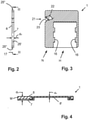
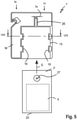
- a card holding device 1 serves to accommodate a conventional card-shaped flat part 2, which is designed as a bank card or customer card with opposite flat sides 3 without elevations of the same is.
- the card-shaped flat part 2 is preferably produced by injection molding and consists of a plastic material in which, for example, a chip with contact surfaces 4 is embedded.
- the card-shaped flat part 2 can have a labeling field 5 on at least one flat side 3, in which information, for example information from the card issuer, for example card issuer logo or advertising information, is listed.
- the card holding device 1 has a housing 6 in and/or on which the card-shaped flat part 2 is held in an inserted position of the same.
- the housing 6 has a flat front wall 7 and a flat rear wall 8, between which an intermediate space 9 is formed, in which a part 10 of the card-shaped flat part 2 is arranged in an inserted position.
- Another part 11 of the card-shaped flat part 2 is not located in the space 9 between the front wall 7 and the rear wall 8 of the housing 6 in the inserted position, but is located in a surface cutout 12 of the front wall 7, resting against a rear side 8' of the rear wall 8 .
- the surface section 12 of the front wall 7 is larger than 50% of the flat side 3 of the card-shaped flat part 2, preferably in the range of 60% to 70% of the flat side 3 of the card-shaped flat part 2, so that the labeling field 5 can be used by a user in the inserted position of the flat part 2 is visible.
- a transverse edge 13 of the front wall 7 facing the insertion side of the housing 6 is offset parallel to an edge 14 of the rear wall 8 arranged on the insertion side of the housing 6 and transverse to an insertion direction E.
- a longitudinal edge 15 of the front wall 7, which is also an edge of the Surface section 12 forms holding means 16 on.
- the holding means 16 are designed as holding extensions, which protrude transversely to the insertion direction E and in the direction of an extension plane 17 of the housing 6 . While a length b1 of the transverse edge 13 corresponds approximately to a width bK of the card-shaped flat part 2, the holding brackets 16 protrude laterally so far that the opposite longitudinal edges 15 in the area of the holding brackets 16 have a clear distance b2 from one another that is smaller than the width b1 of the transverse edge 13 or the width b K of the card-shaped flat part 2.
- the clamping brackets 16 lie on one of the flat sides 3 of the card-shaped flat part 2, while the other flat side 3 of the card-shaped flat part 2 rests on the back 8 'The rear wall 8 rests flat.
- the holding brackets 16 are designed in such a way that the card-shaped flat part 2 is prevented from falling out perpendicularly to the plane of extension 17 of the housing 6 .
- the holding brackets 16 can also be designed in such a way that, when the card-shaped flat part 2 is in the inserted position, they press in the normal direction to the exposed flat side 3 of the card-shaped flat part 2, so that the clamping force exerted by the holding brackets 16 causes the card-shaped flat part 2 to Flat part 2 remains in the inserted position.
- the width b1 of the transverse edge 13 or of the surface cutout 12 can be selected to be smaller than the width bK of the card-shaped flat part 2 such that the card-shaped flat part 2 is clamped in the inserted position.
- the holding brackets 16 do not have a clamping function, but only a holding function in such a way that the card-shaped flat part 2 cannot be moved transversely to the plane 17 of the housing 6 .
- a transverse edge 18 of the flat part 2 which is preferably the size of a credit card according to an ISO standard, is located in the area of a front edge 19 of the housing 6, which connects the front wall 7 and the rear wall 8 and a bottom of the pocket-shaped receptacle forms for the card-shaped flat part 2.
- a transverse edge 20 of the card-shaped flat part 2 opposite the one transverse edge 18 is arranged in the region of the edge 14 of the rear wall 8 in the inserted position.
- the card-shaped flat part 2 is in its inserted position in a main section H of the card holding device 1 or the housing 6 of the same, with the main section H serving to accommodate the card-shaped flat part 2 and having at least the dimensions of the card-shaped flat part 2 in the extension plane 17.
- a belt cutter 21 is arranged in a secondary section N of the housing 6 arranged laterally to the main section H, with a knife 22 of the belt cutter 21 being arranged in a recess 23 on the edge of the secondary section N or of the housing 6 .
- the secondary section N is formed as a solid block M which has no gap, but in which the front wall 7 and the rear wall 8 of the housing 6 merge into one another and/or are connected to one another in one piece over the entire surface. The secondary section N is thus solid.
- the seat belt cutter 21 is located in a front area 24 of the secondary section N, preferably in an area close to a corner of the housing 6 or secondary section N, so that the seat belt cutter 21 can be moved using the longest possible lever arm, namely from the seat belt cutter 21 to the edge 14 of the rear wall 8 can be operated.
- the housing 6 has narrow edge walls 25 both in the main section H and in the secondary section N, with first narrow edge walls 25' long in the insertion direction E and second narrow edge walls 25" running short and transverse to the insertion direction E.
- the narrow edge walls 25', 25" In the area of the secondary section N, the narrow edge walls 25', 25" have a width that corresponds to a thickness d G of the housing 6.
- the first narrow edge wall 25' and the second narrow edge wall 25" facing away from the insertion side correspond to the thickness d G of the housing 6, while the second narrow edge wall 25'' facing the insertion side corresponds to a thickness d R of the rear wall 8.
- the housing 6 is made of a rigid plastics material, preferably by injection moulding.
- the knife 22 of the seat belt cutter 21 is designed as an insert that has been inserted into a mold space of an injection molding machine before plastic mass is injected into the mold space. After the plastic compound has cooled, the housing 6 is produced, with the knife 22 being partially surrounded by the plastic compound.
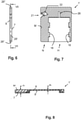
- a card holding device 1' differs from the card holding device 1 described above in that a slot 26 is additionally provided in the front wall 7 in the main section H, so that a spike element 27 of a card-shaped flat part 2' protruding from a flat side 3 can be accommodated.
- the card-shaped flat part 2' serves as a rescue tool for bursting a side window of the vehicle, a leverage force of the bent card-shaped flat part 2' being used to allow the spike element 27 to impact the window pane. So that the mandrel element 27 is prestressed with a minimum lever force, the mandrel element 27 must have a minimum distance from the transverse edge 20, which at the same time forms the pivot axis.
- the slit 26 has a width bs in a range from 2 mm to 7 mm, preferably 3.5 mm, the diameter of the mandrel element 27 being equal to or smaller than the slit width b s .
- a height of the spike element 27 corresponds to the thickness d G of the housing 6 or is smaller than the thickness d G of the housing 6, so that the spike element 27 does not extend beyond the front wall 7 in the inserted position of the card-shaped flat part 2'.
- the thickness d G of the housing 6 corresponds to the distance between the outwardly facing flat sides of the front wall 7 and the rear wall 8.
- the card-shaped flat part 2' has the inscription field 5, but preferably no further information carriers, such as chips, magnetic strips or the like.
- the housing 6 preferably has a rectangular dimension.
- the thickness d G of the housing 6 or the clearance between the front wall 7 and the rear wall 8 in an insertion area of the main section H depends on the number and/or thickness of the card-shaped flat parts 2, 2'. If necessary, the clearance between the front wall 7 and the rear wall 8 can be chosen so that several card-shaped flat parts 2 and/or 2' can be accommodated in the housing 6.
Landscapes
- Purses, Travelling Bags, Baskets, Or Suitcases (AREA)
- Vehicle Step Arrangements And Article Storage (AREA)
Applications Claiming Priority (1)
| Application Number | Priority Date | Filing Date | Title |
|---|---|---|---|
| DE202020105186.5U DE202020105186U1 (de) | 2020-09-09 | 2020-09-09 | Kartenhaltevorrichtung |
Publications (1)
| Publication Number | Publication Date |
|---|---|
| EP3967178A1 true EP3967178A1 (fr) | 2022-03-16 |
Family
ID=72839204
Family Applications (1)
| Application Number | Title | Priority Date | Filing Date |
|---|---|---|---|
| EP21193741.2A Withdrawn EP3967178A1 (fr) | 2020-09-09 | 2021-08-30 | Dispositif de maintien de carte |
Country Status (2)
| Country | Link |
|---|---|
| EP (1) | EP3967178A1 (fr) |
| DE (1) | DE202020105186U1 (fr) |
Citations (5)
| Publication number | Priority date | Publication date | Assignee | Title |
|---|---|---|---|---|
| US5285577A (en) * | 1992-05-22 | 1994-02-15 | Quick Point, Inc. | Letter opener with protected recess for business card and removable slide-in cover |
| DE10351480B3 (de) | 2003-11-04 | 2005-05-25 | Kurt Koch | Vorrichtung zur Einstellung der Parkzeit |
| DE202011051023U1 (de) | 2010-02-16 | 2012-07-05 | Robert Kirchschlager | Kartenhalter |
| US20150033562A1 (en) * | 2013-08-01 | 2015-02-05 | Aletha Ann Posey | Card holder with built in cutter |
| DE102019115480A1 (de) | 2019-06-07 | 2020-12-10 | Cairon Group Gmbh | Rettungswerkzeug zum Öffnen eines verschlossenen Fahrzeugs |
-
2020
- 2020-09-09 DE DE202020105186.5U patent/DE202020105186U1/de active Active
-
2021
- 2021-08-30 EP EP21193741.2A patent/EP3967178A1/fr not_active Withdrawn
Patent Citations (5)
| Publication number | Priority date | Publication date | Assignee | Title |
|---|---|---|---|---|
| US5285577A (en) * | 1992-05-22 | 1994-02-15 | Quick Point, Inc. | Letter opener with protected recess for business card and removable slide-in cover |
| DE10351480B3 (de) | 2003-11-04 | 2005-05-25 | Kurt Koch | Vorrichtung zur Einstellung der Parkzeit |
| DE202011051023U1 (de) | 2010-02-16 | 2012-07-05 | Robert Kirchschlager | Kartenhalter |
| US20150033562A1 (en) * | 2013-08-01 | 2015-02-05 | Aletha Ann Posey | Card holder with built in cutter |
| DE102019115480A1 (de) | 2019-06-07 | 2020-12-10 | Cairon Group Gmbh | Rettungswerkzeug zum Öffnen eines verschlossenen Fahrzeugs |
Also Published As
| Publication number | Publication date |
|---|---|
| DE202020105186U1 (de) | 2020-09-30 |
Similar Documents
| Publication | Publication Date | Title |
|---|---|---|
| EP0823099B1 (fr) | Carte en plastique munie d'une carte amovible a puce miniature | |
| EP0163880B1 (fr) | Support d'information à circuit intégré et procédé de fabrication d'un tel support | |
| EP0729109B1 (fr) | Lecteur de carte à puce | |
| DE29509736U1 (de) | Standardkarte mit eingelagerter Minichipkarte | |
| DE19956497B4 (de) | Fahrzeugtür-Baugruppe | |
| DE2902642A1 (de) | Messer mit zurueckziehbarer klinge | |
| DE102009043373A1 (de) | Vorrichtung zur Aufbewahrung von Klingen | |
| DE19518901A1 (de) | Vorrichtung zum Entwerten von Chipkarten | |
| EP0070439B1 (fr) | Outillage pour desserrer rapidement des moyens passifs de retenue en cas d'urgence dans des véhicules automobiles | |
| DE102010042380A1 (de) | Multifunktionales Rettungswerkzeug | |
| DE202020105186U1 (de) | Kartenhaltevorrichtung | |
| DE9305297U1 (de) | Taschenmesser | |
| EP0617382A2 (fr) | Carte de crédit avec une pièce enfichable amovible | |
| DE102018210988B4 (de) | Verkleidungselement mit Aufnahme für Warndreieck, Heckklappe mit Verkleidungselement und Kraftfahrzeug mit einer solchen Heckklappe | |
| EP3747509B1 (fr) | Outil de sauvetage permettant d'ouvrir un véhicule fermé | |
| EP1476337B1 (fr) | Dispositif d'ouverture d'un palier | |
| DE10248739B4 (de) | Airbagvorrichtung für ein Kraftfahrzeug | |
| DE2704355C2 (de) | Vorrichtung zum Fixieren und Auswerfen eines Gerätes innerhalb eines bzw. aus einem Aufnahmebehälter | |
| DE10211202B4 (de) | Halterung für ein Fahrzeug für eine Karte nach Art einer Scheckkarte | |
| DE29801508U1 (de) | Kunststoffkarte mit aus dieser heraustrennbarer Minichipkarte | |
| DE7710857U1 (de) | Schneidevorrichtung zum Zerschneiden der Sicherheitsgurte eines Kraftfahrzeugs | |
| DE69608799T2 (de) | Kabelschutz | |
| DE19963975A1 (de) | Elektrisches Gerät mit einem Gehäuse | |
| DE8433601U1 (de) | Vorrichtung zum Durchtrennen eines Anschnallgurts | |
| EP0122311A1 (fr) | Instrument coupant destiné à sectionner les ceintures de sécurité des véhicules automobiles |
Legal Events
| Date | Code | Title | Description |
|---|---|---|---|
| PUAI | Public reference made under article 153(3) epc to a published international application that has entered the european phase |
Free format text: ORIGINAL CODE: 0009012 |
|
| STAA | Information on the status of an ep patent application or granted ep patent |
Free format text: STATUS: THE APPLICATION HAS BEEN PUBLISHED |
|
| AK | Designated contracting states |
Kind code of ref document: A1 Designated state(s): AL AT BE BG CH CY CZ DE DK EE ES FI FR GB GR HR HU IE IS IT LI LT LU LV MC MK MT NL NO PL PT RO RS SE SI SK SM TR |
|
| STAA | Information on the status of an ep patent application or granted ep patent |
Free format text: STATUS: THE APPLICATION IS DEEMED TO BE WITHDRAWN |
|
| 18D | Application deemed to be withdrawn |
Effective date: 20220917 |