EP3967341B1 - Seringue dotée d'une fermeture - Google Patents
Seringue dotée d'une fermeture Download PDFInfo
- Publication number
- EP3967341B1 EP3967341B1 EP21192150.7A EP21192150A EP3967341B1 EP 3967341 B1 EP3967341 B1 EP 3967341B1 EP 21192150 A EP21192150 A EP 21192150A EP 3967341 B1 EP3967341 B1 EP 3967341B1
- Authority
- EP
- European Patent Office
- Prior art keywords
- syringe
- stopper
- cap
- barrel
- disposed
- Prior art date
- Legal status (The legal status is an assumption and is not a legal conclusion. Google has not performed a legal analysis and makes no representation as to the accuracy of the status listed.)
- Active
Links
Images




Classifications
-
- A—HUMAN NECESSITIES
- A61—MEDICAL OR VETERINARY SCIENCE; HYGIENE
- A61M—DEVICES FOR INTRODUCING MEDIA INTO, OR ONTO, THE BODY; DEVICES FOR TRANSDUCING BODY MEDIA OR FOR TAKING MEDIA FROM THE BODY; DEVICES FOR PRODUCING OR ENDING SLEEP OR STUPOR
- A61M5/00—Devices for bringing media into the body in a subcutaneous, intra-vascular or intramuscular way; Accessories therefor, e.g. filling or cleaning devices, arm-rests
- A61M5/178—Syringes
- A61M5/20—Automatic syringes, e.g. with automatically actuated piston rod, with automatic needle injection, filling automatically
- A61M5/2053—Media being expelled from injector by pressurised fluid or vacuum
-
- A—HUMAN NECESSITIES
- A61—MEDICAL OR VETERINARY SCIENCE; HYGIENE
- A61M—DEVICES FOR INTRODUCING MEDIA INTO, OR ONTO, THE BODY; DEVICES FOR TRANSDUCING BODY MEDIA OR FOR TAKING MEDIA FROM THE BODY; DEVICES FOR PRODUCING OR ENDING SLEEP OR STUPOR
- A61M5/00—Devices for bringing media into the body in a subcutaneous, intra-vascular or intramuscular way; Accessories therefor, e.g. filling or cleaning devices, arm-rests
- A61M5/178—Syringes
- A61M5/31—Details
- A61M5/315—Pistons; Piston-rods; Guiding, blocking or restricting the movement of the rod or piston; Appliances on the rod for facilitating dosing ; Dosing mechanisms
- A61M5/31501—Means for blocking or restricting the movement of the rod or piston
-
- A—HUMAN NECESSITIES
- A61—MEDICAL OR VETERINARY SCIENCE; HYGIENE
- A61M—DEVICES FOR INTRODUCING MEDIA INTO, OR ONTO, THE BODY; DEVICES FOR TRANSDUCING BODY MEDIA OR FOR TAKING MEDIA FROM THE BODY; DEVICES FOR PRODUCING OR ENDING SLEEP OR STUPOR
- A61M5/00—Devices for bringing media into the body in a subcutaneous, intra-vascular or intramuscular way; Accessories therefor, e.g. filling or cleaning devices, arm-rests
- A61M5/178—Syringes
-
- A—HUMAN NECESSITIES
- A61—MEDICAL OR VETERINARY SCIENCE; HYGIENE
- A61M—DEVICES FOR INTRODUCING MEDIA INTO, OR ONTO, THE BODY; DEVICES FOR TRANSDUCING BODY MEDIA OR FOR TAKING MEDIA FROM THE BODY; DEVICES FOR PRODUCING OR ENDING SLEEP OR STUPOR
- A61M5/00—Devices for bringing media into the body in a subcutaneous, intra-vascular or intramuscular way; Accessories therefor, e.g. filling or cleaning devices, arm-rests
- A61M5/178—Syringes
- A61M5/31—Details
- A61M5/3129—Syringe barrels
-
- A—HUMAN NECESSITIES
- A61—MEDICAL OR VETERINARY SCIENCE; HYGIENE
- A61M—DEVICES FOR INTRODUCING MEDIA INTO, OR ONTO, THE BODY; DEVICES FOR TRANSDUCING BODY MEDIA OR FOR TAKING MEDIA FROM THE BODY; DEVICES FOR PRODUCING OR ENDING SLEEP OR STUPOR
- A61M5/00—Devices for bringing media into the body in a subcutaneous, intra-vascular or intramuscular way; Accessories therefor, e.g. filling or cleaning devices, arm-rests
- A61M5/178—Syringes
- A61M5/31—Details
- A61M5/3129—Syringe barrels
- A61M5/3135—Syringe barrels characterised by constructional features of the proximal end
-
- A—HUMAN NECESSITIES
- A61—MEDICAL OR VETERINARY SCIENCE; HYGIENE
- A61M—DEVICES FOR INTRODUCING MEDIA INTO, OR ONTO, THE BODY; DEVICES FOR TRANSDUCING BODY MEDIA OR FOR TAKING MEDIA FROM THE BODY; DEVICES FOR PRODUCING OR ENDING SLEEP OR STUPOR
- A61M5/00—Devices for bringing media into the body in a subcutaneous, intra-vascular or intramuscular way; Accessories therefor, e.g. filling or cleaning devices, arm-rests
- A61M5/178—Syringes
- A61M5/31—Details
- A61M5/3145—Filters incorporated in syringes
-
- A—HUMAN NECESSITIES
- A61—MEDICAL OR VETERINARY SCIENCE; HYGIENE
- A61M—DEVICES FOR INTRODUCING MEDIA INTO, OR ONTO, THE BODY; DEVICES FOR TRANSDUCING BODY MEDIA OR FOR TAKING MEDIA FROM THE BODY; DEVICES FOR PRODUCING OR ENDING SLEEP OR STUPOR
- A61M5/00—Devices for bringing media into the body in a subcutaneous, intra-vascular or intramuscular way; Accessories therefor, e.g. filling or cleaning devices, arm-rests
- A61M5/178—Syringes
- A61M5/31—Details
- A61M5/315—Pistons; Piston-rods; Guiding, blocking or restricting the movement of the rod or piston; Appliances on the rod for facilitating dosing ; Dosing mechanisms
- A61M5/31511—Piston or piston-rod constructions, e.g. connection of piston with piston-rod
- A61M5/31513—Piston constructions to improve sealing or sliding
-
- A—HUMAN NECESSITIES
- A61—MEDICAL OR VETERINARY SCIENCE; HYGIENE
- A61M—DEVICES FOR INTRODUCING MEDIA INTO, OR ONTO, THE BODY; DEVICES FOR TRANSDUCING BODY MEDIA OR FOR TAKING MEDIA FROM THE BODY; DEVICES FOR PRODUCING OR ENDING SLEEP OR STUPOR
- A61M5/00—Devices for bringing media into the body in a subcutaneous, intra-vascular or intramuscular way; Accessories therefor, e.g. filling or cleaning devices, arm-rests
- A61M5/178—Syringes
- A61M5/31—Details
- A61M5/32—Needles; Details of needles pertaining to their connection with syringe or hub; Accessories for bringing the needle into, or holding the needle on, the body; Devices for protection of needles
- A61M5/3202—Devices for protection of the needle before use, e.g. caps
-
- A—HUMAN NECESSITIES
- A61—MEDICAL OR VETERINARY SCIENCE; HYGIENE
- A61M—DEVICES FOR INTRODUCING MEDIA INTO, OR ONTO, THE BODY; DEVICES FOR TRANSDUCING BODY MEDIA OR FOR TAKING MEDIA FROM THE BODY; DEVICES FOR PRODUCING OR ENDING SLEEP OR STUPOR
- A61M5/00—Devices for bringing media into the body in a subcutaneous, intra-vascular or intramuscular way; Accessories therefor, e.g. filling or cleaning devices, arm-rests
- A61M5/178—Syringes
- A61M5/31—Details
- A61M2005/3103—Leak prevention means for distal end of syringes, i.e. syringe end for mounting a needle
- A61M2005/3107—Leak prevention means for distal end of syringes, i.e. syringe end for mounting a needle for needles
- A61M2005/3109—Caps sealing the needle bore by use of, e.g. air-hardening adhesive, elastomer or epoxy resin
-
- A—HUMAN NECESSITIES
- A61—MEDICAL OR VETERINARY SCIENCE; HYGIENE
- A61M—DEVICES FOR INTRODUCING MEDIA INTO, OR ONTO, THE BODY; DEVICES FOR TRANSDUCING BODY MEDIA OR FOR TAKING MEDIA FROM THE BODY; DEVICES FOR PRODUCING OR ENDING SLEEP OR STUPOR
- A61M5/00—Devices for bringing media into the body in a subcutaneous, intra-vascular or intramuscular way; Accessories therefor, e.g. filling or cleaning devices, arm-rests
- A61M5/178—Syringes
- A61M5/31—Details
- A61M2005/3123—Details having air entrapping or venting means, e.g. purging channels in pistons
Definitions
- the present disclosure is generally directed to a closure for a syringe. More particularly, the present disclosure is directed to a closure for a syringe intended to interface with a pneumatic driving system, or driver, and to provide a seal over a range of temperatures.
- cell-based therapies most commonly have been delivered from flexible plastic containers, or bags.
- bags With most cell-based therapeutics requiring cryopreservation at liquid nitrogen temperatures to preserve cell function during shipping or patient preparations regimens, bags present several challenges.
- the bags can be fragile when frozen, and are susceptible to breakage and/or contamination.
- fluids held up in the bag can prevent incomplete dosing.
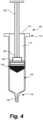
- a syringe 100 includes a barrel 102, a plunger 104, and a vented closure 106.
- the syringe 100 may be used to contain, for example, a cell-based medicine, and may be adapted to store that medicine at a variety of temperatures.
- the syringe 100 may provide a container that is a ready-to-use delivery vessel, pre-filled syringes 100 being used alone or as a component of an autoinjector or autoinfuser.
- the syringe 100 described herein may be used with pneumatic driving system, or drivers, to reduce the risks of contamination during filling.
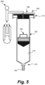
- the vented closure 106 permits a pneumatic driver to be attached to the syringe 100 to move the plunger 104 along the bore 110. See Fig. 5 . Because only filtered gas (e.g., air) enters and exits the bore 110 to move the plunger 104, the possible contamination risks that might be related to the use of a mechanical driver (including plunger handle and linear actuator) entering the bore through an open end can be eliminated. Further, the stopper 120 provides a further seal useful under cryopreservation conditions, thereby reducing the role that the plunger 104 has to play under such conditions in sealing the bore 110. Further, where the closure 106 is removeable, the syringe 100 represents an easily configurable, ready-to-use delivery vessel.
- filtered gas e.g., air
- the barrel 102 has a first end 112, the first end 112 including the opening 114 and the barrel flange 116, and a second end 118 located at the opposite end of the barrel 102.
- the barrel 102 may have a tip 140 at the second end 118, the tip 140 being in fluid communication with the bore 110.
- the tip 140 may be configured to connect to a needle, for example as a luer lock or a luer slip tip.
- the tip 140 may include a septum that will be pierced by a canula that is attached to or is part of a delivery system, such as may be found in an autoinjector or autoinfuser device.
- the tip 140 may be closed with a cap or cover (not shown) in storage, or when not in use.
- the barrel flange 116 may depend outwardly from the barrel 102, but may not depend radially outwardly from the barrel 102 to the same distance in all directions. See, e.g., Fig. 2 . That is, the barrel flange 116 may not form an annular shelf depending from the barrel in a cantilevered fashion, but instead may be in the form of two opposite cantilevered structures that depend from the barrel 102 from opposite sides (e.g., left and right) of the barrel 102. These structures may be used during delivery of the medicine from the syringe 100, by placing the index and middle fingers against the flange 116 while depressing on a plunger handle that is attached to the plunger 104. In other variants, the barrel flange 116 may be too narrow to be used in this fashion, with index and middle fingers disposed against the flange 116.
- the fastener 128 includes a skirt 160 that depends from the body 126, at least those regions that overlie the barrel flange 116, the skirt 160 having one or more barbs 162 depending therefrom.
- the barb(s) 162 cooperated with the barrel flange 116 to secure the stopper in place, and may also cause the cap 122 to compress the stopper 120 to create a hermetic static seal in the bore 110, which hermetic seal may be compatible with room temperature, refrigeration, and cryogenic storage.
- the cap 122 includes a skirt 160 that depends downwardly from the body 126. It will be recognized that directional references are adopted herein for the convenience of the reader, such that downward does not place an absolute limitation on the nature of the skirt 160. Instead, it is meant to convey that the skirt 160 depends from the cap 122 in a direction toward the barrel flange 116 , considering that the cap 122 previously been described as disposed over the stopper flange 156, which in turn overlies the barrel flange 116.
- the skirt 160 is not continuous about the perimeter of the body 126 of the cap 122, although it could be according to certain embodiments. Instead the skirt 160 includes two sections, each of which borders the sections of the body 126 the overlie the barrel flange 116. This skirt 160 could, in other embodiments, be divided even further, so as to define a plurality of skirt sections, or fingers. In the same fashion that the barb 162 is defined along the perimeter of the skirt sections 160 illustrated, each of these fingers could have a barb disposed at a downward end thereof, each barb cooperating with the barrel flange 116. Such an arrangement may provide for a more flexible skirt 160 overall, making separation of the closure 106 from the barrel 102 easier.
- the engagement of the surfaces 166, 168 is the primary attachment mechanism between the barrel 102 and the snap-fit closure 106, such that with sufficient force applied to the closure 106, the closure 106 may be separated from the barrel 102.
- the closure 106 may be referred to as removable even if the force applied causes permanent deformation, or even failure, of the cap 122 (and in particular the skirt 160).
- the skirt 160 and/or barbs 162 may be separated from the cap 122 to permit the closure 106 to be removed from the barrel 102.
- the closure 106 may be removeable so that, after filling, a mechanical control mechanism can cooperate with the plunger 104 directly. That is, the closure 106 is designed to permit gas (e.g., air) to move the plunger 104 along the bore 110.
- gas e.g., air
- a pneumatic system may be used during filling to move the plunger 104
- a large number of delivery systems use mechanical control mechanisms instead of gaseous ones.
- the closure 106 may be removed so that a first end 180 of a plunger handle 182 may be disposed through the opening 114 and into the bore 110.
- the plunger 104 may have an attachment mechanism 184 formed therein or on a surface thereof that cooperates with the plunger handle 182, for example the first end 180.
- the closure 106 is vented, which venting permits the syringe 100 to be used with a pneumatic driver during filing, and perhaps also with a gaseous driver as part of a delivery system.
- the stopper 120 and the body 126 of the cap 122 each have at least one through-lumen 190, 192 according to the illustrated embodiment. See Figs. 1 and 3 .
- the through-lumens 190, 192 of the stopper 120 and cap 122 are aligned along a common longitudinal axis 194, which axis 194 happens to be central axis of the syringe 100 as well.
- the filter 124 may be embedded in the stopper 120 or the cap 122. According to such an embodiment, the filter 124 may be in one of the through-lumens 190, 192, for example, but still at the junction between the through-lumens 190, 192. According to still other embodiments, the filter 124 may be disposed not between the through-lumens 190, 192, but at an inner end of the through-lumen 190 or an outer end of the through lumen 192. Further alternative arrangements are also possible.
- the closure 106 may be used with a pneumatic driver, as mentioned above.
- the closure 106 may be connected to the pneumatic driver, such as the driver 200 illustrated in Fig. 5 .
- the pneumatic driver 200 may be in the form of a pneumatic pump, for example, and may be capable of coupling pressure, vacuum or vent to the syringe 100.
- the pneumatic driver may include a combination of valves and pressurized reservoirs.
- the filter 324 is disposed on the stopper 120, or according to certain embodiments the filter 324 is joined to the stopper 120,
- the cap 322 is then disposed over the stopper 120 and filter 324, as seen in Fig. 8A .
- the fasteners 328 may then be brought from a first position or state illustrated in Fig. 8A to a second position or state illustrated in Fig. 8B .
- the barbs 362 are spaced radially outward of the body 326 of the cap 322, thereby limiting interference between the barbs 362 and the barrel flange 116 (or collar, in those embodiments where included) as the cap 322 is fitted onto the syringe.
- the barbs 362 are brought into the second position where the surfaces 366, 368 abut to secure the cap 322 (and the closure 306) to the syringe 100.
- the fastener 428 is in the form of a C-shaped clamp 460, as viewed in the cross-section of Fig. 9A . It may be suggested that the clamp 460 performs the function of the skirt and the barb in the previous embodiments.
- the clamp 460 includes an upper section 462, a lower section 464, and a bridging section 466 that connects the upper section 462 to the lower section 464.
- the upper section 462 has two connectors 480, 482 disposed on opposite sides of the clamp 460 (which may also be opposite sides of the syringe 100).
- the lower section 464 may also have connectors (not shown) disposed on opposite sides of the clamp 460. While one arrangement has been illustrated, this not the only possible configuration for the connectors.
- the connectors may be configured such that one half (e.g., the right half 478) has only the barbs 484, and the other half (e.g., the left half 476) has only the recesses configured to receive the barbs 484.
- the connectors of the upper section 462 may have barbs 484 on the right half 478 and recesses on the left half 476, while the lower section 464 has barbs on the left half 476 and recesses 486 on the right half 478.
- the connector 480 may have a barb 484 on the right half 478 and a recess 486 on the left half 476, while the connector 482 has a barb 484 on the left half 476 and a recess 486 on the right half 478.
- the connectors on the lower section 464 may be the same as their counterparts on the upper section 462, or may be reversed.
- the fastener 428 (and specifically the clamp 460) has having right and left halves 476, 478, this has been done for ease of explanation.
- the clamp 460 may have two relatively equal parts that are joined together to form the clamp 460, but it is not required that each part be exactly or approximately 50% of the overall structure. Further, while the clamp 460 has been illustrated as disposed about the entire periphery of the barrel flange 116 and stopper flange 156, this need not be the case with every instance of this embodiment of the closure 406.
- the filter 424 may be disposed over the stopper 120, and then the body 426 is disposed over the filter 424 and the stopper 120.
- a downward force may be applied to the body 426 to the filter 424 and stopper 120 as the halves 476 and 478 are advanced toward the syringe 100 from opposite sides of the syringe 100.
- the inner surface 468 of the upper section 462 of the clamp faces, and may even abut, the outer surface 470 of the body 426, and the inner surface 472 faces, and may even abut, the outer surface 474 of the barrel flange 116.
- the halves 476, 478 are advanced toward each other until the barbs 484 are advanced so far in the direction of the recess 486 that the barbs 484 and recess 486 mate, connecting the two halves 476, 478 of the clamp 460 together. In this position or state, the body 426, filter 424 and stopper 120, and barrel flange 116 are disposed between the opposing surfaces 468, 472 of the clamp 460.
Landscapes
- Health & Medical Sciences (AREA)
- Vascular Medicine (AREA)
- Engineering & Computer Science (AREA)
- Anesthesiology (AREA)
- Biomedical Technology (AREA)
- Heart & Thoracic Surgery (AREA)
- Hematology (AREA)
- Life Sciences & Earth Sciences (AREA)
- Animal Behavior & Ethology (AREA)
- General Health & Medical Sciences (AREA)
- Public Health (AREA)
- Veterinary Medicine (AREA)
- Infusion, Injection, And Reservoir Apparatuses (AREA)
Claims (15)
- Seringue (100) comprenant :un cylindre (102) avec un alésage (110), le cylindre présentant une extrémité (112) avec une ouverture (114) en communication avec l'alésage et un rebord de cylindre (116) disposé vers l'extérieur de l'ouverture (114),un piston (104) disposé dans l'alésage (110), le piston (104) pouvant être déplacé le long de l'alésage (110) ; etune fermeture aérée (106, 206, 306, 406) fixée au cylindre (102) sur l'extrémité (112), la fermeture aérée (106, 206, 306) comprenant une butée (120), un capuchon (122, 222, 322, 422) et un filtre (124, 224, 324, 424),la butée (120) étant disposée au-dessus de l'ouverture (114) et au moins en partie à l'intérieur de l'alésage (110),le capuchon (122, 222, 322, 422) présentant un corps (126, 226, 326, 426) disposé au-dessus de la butée (120), et un élément de fixation (128, 228, 328, 428) en prise avec le rebord de cylindre (116),le filtre (124, 224, 324, 424) étant disposé entre la butée (120) et le capuchon (122, 222, 322, 422), ou dans au moins un élément de la butée (120) et du capuchon (122, 222, 322, 422),caractérisée en ce que la butée (120) comprend une première extrémité (150) comprenant un bouchon (152) disposé à l'intérieur de l'alésage (110) et une deuxième extrémité (154) comprenant un rebord de butée (156) dépendant de la deuxième extrémité (154) de la butée (120) à l'extérieur de l'alésage (110), et le capuchon (122, 222, 322, 422) bloque le rebord de butée (156) entre le corps (126) du capuchon (122, 222, 322, 422) et le rebord de cylindre (116).
- Seringue (100) selon la revendication 1, dans laquelle le rebord de cylindre (116) est défini par un collet (142) disposé sur le cylindre (102) sur l'extrémité (112) de celui-ci.
- Seringue selon la revendication 1 ou 2, dans laquelle la butée comprend un matériau élastomère.
- Seringue (100) selon l'une quelconque des revendications 1-3, dans laquelle la fermeture aérée (106, 206, 306) comprend un collet (142, 268) qui vient en butée contre le rebord de cylindre (116), et l'élément de fixation (128, 228, 328) comprend une jupe (160, 260, 360) dépendant du corps (126, 226, 326) du capuchon (122, 222, 322, 422) et présentant un ardillon (162, 262, 362) qui vient en prise avec le rebord de cylindre (116) ou le collet (142, 268).
- Seringue selon l'une quelconque des revendications 1-4, dans laquelle l'élément de fixation (328) est attaché au corps (326) du capuchon (322) par une charnière (370).
- Seringue (100) selon l'une quelconque des revendications 1-3, dans laquelle l'élément de fixation (428) comprend une pince (460) présentant des surfaces intérieures opposées (468, 472), et au moins une partie de la butée (120) et le rebord de cylindre (116) sont disposés entre les surfaces intérieures opposées (468, 472) de la pince (460), et la pince (460) est disposée autour de la périphérie de la seringue (100) et est divisée en au moins deux parties (476, 478) qui sont reliées à l'au moins une partie de la butée (120) et au rebord de cylindre (116) disposés entre les surfaces intérieures opposées (468, 472) de la pince (460).
- Seringue (100) selon la revendication 6, dans laquelle le corps (426) du capuchon (422) est séparé de la pince (460), et le corps (426) du capuchon (422), l'au moins une partie de la butée (120), et le rebord de cylindre (116) sont disposés entre les surfaces intérieures opposées (468, 472) de la pince (460).
- Seringue (100) selon l'une quelconque des revendications 1-7, dans laquelle le capuchon (122, 222, 322, 422) est configuré pour comprimer la butée (120) pour créer un joint hermétique dans l'alésage (110).
- Seringue (100) selon l'une quelconque des revendications 1-8, dans laquelle la butée (120) et le corps (126) du capuchon (122, 222, 322, 422) présentent chacun une lumière traversante (190, 192), et le filtre (124) est disposé entre la lumière traversante de la butée (190) et la lumière traversante du capuchon (192).
- Seringue selon la revendication 1, comprenant en outre une poignée de piston (182) lorsque la fermeture aérée (106, 206, 306, 406) n'est pas attachée au cylindre (102), la poignée de piston (182) étant disposée à travers l'ouverture (114) et dans l'alésage (110), la poignée de piston (182) pouvant être attachée au piston (104) pour commander le déplacement du piston (104) le long de l'alésage (110).
- Seringue selon l'une quelconque des revendications 1-10, dans laquelle le filtre (124, 224, 324, 424) comprend 0,22 micron d'un milieu filtrant.
- Seringue selon l'une quelconque des revendications 1-11, dans laquelle le cylindre (102) comprend un copolymère d'oléfine cyclique.
- Seringue (100) selon l'une quelconque des revendications 1-12, dans laquelle le cylindre (102) présente une deuxième extrémité (154) opposée à l'extrémité (112), le piston (104) pouvant être déplacé le long de l'alésage (110) entre l'extrémité (112) et la deuxième extrémité (154), la deuxième extrémité (154) comprenant une pointe (140) en communication fluidique avec l'alésage (110).
- Ensemble de traitement, comprenant un tube et au moins une seringue (100) selon la revendication 13, la pointe (140) de l'au moins une seringue étant reliée au tube.
- Système de traitement comprenant un système d'entraînement pneumatique (200) relié à la fermeture aérée (106) d'une seringue (100) selon l'une quelconque des revendications 1-13.
Applications Claiming Priority (1)
| Application Number | Priority Date | Filing Date | Title |
|---|---|---|---|
| US202063076843P | 2020-09-10 | 2020-09-10 |
Publications (3)
| Publication Number | Publication Date |
|---|---|
| EP3967341A1 EP3967341A1 (fr) | 2022-03-16 |
| EP3967341C0 EP3967341C0 (fr) | 2025-07-09 |
| EP3967341B1 true EP3967341B1 (fr) | 2025-07-09 |
Family
ID=77411637
Family Applications (1)
| Application Number | Title | Priority Date | Filing Date |
|---|---|---|---|
| EP21192150.7A Active EP3967341B1 (fr) | 2020-09-10 | 2021-08-19 | Seringue dotée d'une fermeture |
Country Status (4)
| Country | Link |
|---|---|
| US (1) | US12303671B2 (fr) |
| EP (1) | EP3967341B1 (fr) |
| JP (1) | JP7805729B2 (fr) |
| CN (1) | CN114159647B (fr) |
Families Citing this family (6)
| Publication number | Priority date | Publication date | Assignee | Title |
|---|---|---|---|---|
| JP7094906B2 (ja) * | 2019-02-15 | 2022-07-04 | 三菱重工業株式会社 | 流動性材料吐出装置 |
| USD920519S1 (en) * | 2019-06-28 | 2021-05-25 | Oertli-Instrumente Ag | Medical instrument for eye surgical purposes |
| AU2023406314A1 (en) * | 2022-12-01 | 2025-07-17 | Discgenics, Inc. | Capped syringes and methods of sealing same |
| WO2024168243A1 (fr) * | 2023-02-09 | 2024-08-15 | West Pharmaceutical Services, Inc. | Systèmes contenants et procédés de stockage et de distribution cryogéniques de bioencre |
| WO2026027500A1 (fr) * | 2024-08-01 | 2026-02-05 | Sanofi | Récipient de médicament, dispositif d'injection et procédé de stockage ou de conservation d'un médicament dans un récipient de médicament |
| CN118753559A (zh) * | 2024-09-06 | 2024-10-11 | 穆恩制药设备(杭州)有限公司 | 预充式注射器的无菌灌装方法 |
Family Cites Families (21)
| Publication number | Priority date | Publication date | Assignee | Title |
|---|---|---|---|---|
| US2186987A (en) * | 1938-08-05 | 1940-01-16 | Baxter Laboratories Inc | Filter flow device |
| US2372227A (en) * | 1940-12-24 | 1945-03-27 | Hugh W Sanford | Closure |
| US4251003A (en) * | 1979-01-19 | 1981-02-17 | Toni Casutt | Bottle closing device |
| US4231494A (en) * | 1979-03-22 | 1980-11-04 | Greenwood David L | Syringe adaptor assembly |
| US5019037A (en) * | 1989-07-06 | 1991-05-28 | Alcon Laboratories, Inc. | Pneumatic retinopexy injector |
| US5165560A (en) * | 1992-03-26 | 1992-11-24 | Genesis Industries, Inc. | Nonrotating hermetically sealed closure for bottle containing liquid |
| US5873499A (en) * | 1996-08-14 | 1999-02-23 | Scientific Resources, Inc. | Pressure breakaway dispensing gun |
| US5887764A (en) * | 1996-11-27 | 1999-03-30 | Ennis, Iii; James F. | Apparatus for a pressurized injector |
| DE19929325A1 (de) * | 1999-06-26 | 2001-01-18 | Vetter & Co Apotheker | Spritze für medizinische Zwecke |
| US7243689B2 (en) * | 2000-02-11 | 2007-07-17 | Medical Instill Technologies, Inc. | Device with needle penetrable and laser resealable portion and related method |
| US6595961B2 (en) * | 2001-04-16 | 2003-07-22 | Becton, Dickinson And Company | Sterilizable transfer or storage device for medicaments, drugs and vaccines |
| JP4050579B2 (ja) | 2002-09-11 | 2008-02-20 | テルモ株式会社 | プレフィルドシリンジ |
| US9283148B2 (en) * | 2011-03-07 | 2016-03-15 | Medela Holding Ag | Multi-purpose syringe |
| US20140263403A1 (en) * | 2013-03-15 | 2014-09-18 | Nordson Corporation | Liquid Dispensing Syringe |
| US9498574B2 (en) * | 2013-03-15 | 2016-11-22 | Carefusion 303, Inc. | Infusion system with dual-chambered reservoir |
| US10258502B2 (en) * | 2014-09-18 | 2019-04-16 | Orbit Biomedical Limited | Therapeutic agent delivery device |
| KR102541205B1 (ko) * | 2015-02-20 | 2023-06-09 | 리제너론 파아마슈티컬스, 인크. | 주사기 시스템, 피스톤 시일 시스템, 스토퍼 시스템 및 사용 방법 및 조립체 |
| EP3522956B1 (fr) * | 2016-10-05 | 2021-03-24 | Cane' S.p.A. | Dispositif pour remplir et purger des seringues |
| EP3858395A1 (fr) * | 2016-12-01 | 2021-08-04 | Fenwal, Inc. | Systèmes et procédés de remplissage et de finition |
| JP6808229B2 (ja) * | 2017-03-27 | 2021-01-06 | 武蔵エンジニアリング株式会社 | 液体材料貯留容器用蓋および液体材料貯留容器 |
| US11684725B2 (en) * | 2018-12-19 | 2023-06-27 | Fenwal, Inc. | Disposable syringe for use with pneumatic drivers |
-
2021
- 2021-08-19 EP EP21192150.7A patent/EP3967341B1/fr active Active
- 2021-09-02 JP JP2021143187A patent/JP7805729B2/ja active Active
- 2021-09-03 CN CN202111032861.4A patent/CN114159647B/zh active Active
- 2021-09-03 US US17/466,083 patent/US12303671B2/en active Active
Also Published As
| Publication number | Publication date |
|---|---|
| US12303671B2 (en) | 2025-05-20 |
| JP2022046439A (ja) | 2022-03-23 |
| CN114159647A (zh) | 2022-03-11 |
| EP3967341C0 (fr) | 2025-07-09 |
| JP7805729B2 (ja) | 2026-01-26 |
| EP3967341A1 (fr) | 2022-03-16 |
| US20220072234A1 (en) | 2022-03-10 |
| CN114159647B (zh) | 2026-01-06 |
Similar Documents
| Publication | Publication Date | Title |
|---|---|---|
| EP3967341B1 (fr) | Seringue dotée d'une fermeture | |
| US20240108548A1 (en) | Pre-filled diluent syringe vial adapter | |
| EP2271387B1 (fr) | Dispositif de transfert de fluide à contenant double | |
| US5445630A (en) | Spike with luer fitting | |
| US5405333A (en) | Liquid medicament bag with needleless connector fitting using boat assembly | |
| EP0761562B1 (fr) | Raccord stérile rescellable de fiole | |
| EP2804645B1 (fr) | Flacon à doses multiples et procédé | |
| US7905873B2 (en) | Port assembly for use with needleless connector | |
| US5871110A (en) | Transfer assembly for a medicament container having a splashless valve | |
| US10478382B2 (en) | Medical connecting device | |
| JP2019022778A (ja) | ロッキング部材を含む、流体の密閉された移送のためのシステム | |
| AU2011217306B2 (en) | Closure cap for a receptacle for receiving medical liquids, and receptacle | |
| US20040059312A1 (en) | Ampule for packaging and transferring a liquid or a powder for medical use | |
| EP3562753B1 (fr) | Fermeture de récipient actionnée par un dispositif de connexion | |
| AU771466B2 (en) | Membrane port for a container | |
| EP3562752B1 (fr) | Fermeture de récipient actionnée par rotation | |
| EP3107600B1 (fr) | Dispositif de vanne d'aspiration | |
| EP4124330A1 (fr) | Appareil et système de mélange de composants comprenant une canule de transfert de fluide |
Legal Events
| Date | Code | Title | Description |
|---|---|---|---|
| PUAI | Public reference made under article 153(3) epc to a published international application that has entered the european phase |
Free format text: ORIGINAL CODE: 0009012 |
|
| STAA | Information on the status of an ep patent application or granted ep patent |
Free format text: STATUS: THE APPLICATION HAS BEEN PUBLISHED |
|
| AK | Designated contracting states |
Kind code of ref document: A1 Designated state(s): AL AT BE BG CH CY CZ DE DK EE ES FI FR GB GR HR HU IE IS IT LI LT LU LV MC MK MT NL NO PL PT RO RS SE SI SK SM TR |
|
| STAA | Information on the status of an ep patent application or granted ep patent |
Free format text: STATUS: REQUEST FOR EXAMINATION WAS MADE |
|
| 17P | Request for examination filed |
Effective date: 20220829 |
|
| RBV | Designated contracting states (corrected) |
Designated state(s): AL AT BE BG CH CY CZ DE DK EE ES FI FR GB GR HR HU IE IS IT LI LT LU LV MC MK MT NL NO PL PT RO RS SE SI SK SM TR |
|
| GRAP | Despatch of communication of intention to grant a patent |
Free format text: ORIGINAL CODE: EPIDOSNIGR1 |
|
| STAA | Information on the status of an ep patent application or granted ep patent |
Free format text: STATUS: GRANT OF PATENT IS INTENDED |
|
| INTG | Intention to grant announced |
Effective date: 20241223 |
|
| GRAS | Grant fee paid |
Free format text: ORIGINAL CODE: EPIDOSNIGR3 |
|
| GRAJ | Information related to disapproval of communication of intention to grant by the applicant or resumption of examination proceedings by the epo deleted |
Free format text: ORIGINAL CODE: EPIDOSDIGR1 |
|
| GRAL | Information related to payment of fee for publishing/printing deleted |
Free format text: ORIGINAL CODE: EPIDOSDIGR3 |
|
| STAA | Information on the status of an ep patent application or granted ep patent |
Free format text: STATUS: REQUEST FOR EXAMINATION WAS MADE |
|
| GRAP | Despatch of communication of intention to grant a patent |
Free format text: ORIGINAL CODE: EPIDOSNIGR1 |
|
| STAA | Information on the status of an ep patent application or granted ep patent |
Free format text: STATUS: GRANT OF PATENT IS INTENDED |
|
| INTC | Intention to grant announced (deleted) | ||
| INTG | Intention to grant announced |
Effective date: 20250507 |
|
| GRAA | (expected) grant |
Free format text: ORIGINAL CODE: 0009210 |
|
| STAA | Information on the status of an ep patent application or granted ep patent |
Free format text: STATUS: THE PATENT HAS BEEN GRANTED |
|
| AK | Designated contracting states |
Kind code of ref document: B1 Designated state(s): AL AT BE BG CH CY CZ DE DK EE ES FI FR GB GR HR HU IE IS IT LI LT LU LV MC MK MT NL NO PL PT RO RS SE SI SK SM TR |
|
| REG | Reference to a national code |
Ref country code: GB Ref legal event code: FG4D |
|
| REG | Reference to a national code |
Ref country code: CH Ref legal event code: EP |
|
| REG | Reference to a national code |
Ref country code: DE Ref legal event code: R096 Ref document number: 602021033664 Country of ref document: DE |
|
| REG | Reference to a national code |
Ref country code: IE Ref legal event code: FG4D |
|
| U01 | Request for unitary effect filed |
Effective date: 20250728 |
|
| U07 | Unitary effect registered |
Designated state(s): AT BE BG DE DK EE FI FR IT LT LU LV MT NL PT RO SE SI Effective date: 20250801 |
|
| U20 | Renewal fee for the european patent with unitary effect paid |
Year of fee payment: 5 Effective date: 20250827 |
|
| PGFP | Annual fee paid to national office [announced via postgrant information from national office to epo] |
Ref country code: GB Payment date: 20250827 Year of fee payment: 5 |
|
| PG25 | Lapsed in a contracting state [announced via postgrant information from national office to epo] |
Ref country code: IS Free format text: LAPSE BECAUSE OF FAILURE TO SUBMIT A TRANSLATION OF THE DESCRIPTION OR TO PAY THE FEE WITHIN THE PRESCRIBED TIME-LIMIT Effective date: 20251109 |
|
| PG25 | Lapsed in a contracting state [announced via postgrant information from national office to epo] |
Ref country code: NO Free format text: LAPSE BECAUSE OF FAILURE TO SUBMIT A TRANSLATION OF THE DESCRIPTION OR TO PAY THE FEE WITHIN THE PRESCRIBED TIME-LIMIT Effective date: 20251009 |
|
| PG25 | Lapsed in a contracting state [announced via postgrant information from national office to epo] |
Ref country code: HR Free format text: LAPSE BECAUSE OF FAILURE TO SUBMIT A TRANSLATION OF THE DESCRIPTION OR TO PAY THE FEE WITHIN THE PRESCRIBED TIME-LIMIT Effective date: 20250709 |
|
| PG25 | Lapsed in a contracting state [announced via postgrant information from national office to epo] |
Ref country code: GR Free format text: LAPSE BECAUSE OF FAILURE TO SUBMIT A TRANSLATION OF THE DESCRIPTION OR TO PAY THE FEE WITHIN THE PRESCRIBED TIME-LIMIT Effective date: 20251010 |
|
| PG25 | Lapsed in a contracting state [announced via postgrant information from national office to epo] |
Ref country code: PL Free format text: LAPSE BECAUSE OF FAILURE TO SUBMIT A TRANSLATION OF THE DESCRIPTION OR TO PAY THE FEE WITHIN THE PRESCRIBED TIME-LIMIT Effective date: 20250709 |
|
| PG25 | Lapsed in a contracting state [announced via postgrant information from national office to epo] |
Ref country code: RS Free format text: LAPSE BECAUSE OF FAILURE TO SUBMIT A TRANSLATION OF THE DESCRIPTION OR TO PAY THE FEE WITHIN THE PRESCRIBED TIME-LIMIT Effective date: 20251009 |
|
| PG25 | Lapsed in a contracting state [announced via postgrant information from national office to epo] |
Ref country code: ES Free format text: LAPSE BECAUSE OF FAILURE TO SUBMIT A TRANSLATION OF THE DESCRIPTION OR TO PAY THE FEE WITHIN THE PRESCRIBED TIME-LIMIT Effective date: 20250709 |
|
| REG | Reference to a national code |
Ref country code: CH Ref legal event code: H13 Free format text: ST27 STATUS EVENT CODE: U-0-0-H10-H13 (AS PROVIDED BY THE NATIONAL OFFICE) Effective date: 20260324 |
|
| PG25 | Lapsed in a contracting state [announced via postgrant information from national office to epo] |
Ref country code: SM Free format text: LAPSE BECAUSE OF FAILURE TO SUBMIT A TRANSLATION OF THE DESCRIPTION OR TO PAY THE FEE WITHIN THE PRESCRIBED TIME-LIMIT Effective date: 20250709 |