EP3967384A1 - Dispositif de traitement de boue et machine de travail de système de traitement de boue - Google Patents
Dispositif de traitement de boue et machine de travail de système de traitement de boue Download PDFInfo
- Publication number
- EP3967384A1 EP3967384A1 EP20831778.4A EP20831778A EP3967384A1 EP 3967384 A1 EP3967384 A1 EP 3967384A1 EP 20831778 A EP20831778 A EP 20831778A EP 3967384 A1 EP3967384 A1 EP 3967384A1
- Authority
- EP
- European Patent Office
- Prior art keywords
- liquid
- tank
- flow path
- sludge treatment
- treatment device
- Prior art date
- Legal status (The legal status is an assumption and is not a legal conclusion. Google has not performed a legal analysis and makes no representation as to the accuracy of the status listed.)
- Withdrawn
Links
Images




Classifications
-
- B—PERFORMING OPERATIONS; TRANSPORTING
- B01—PHYSICAL OR CHEMICAL PROCESSES OR APPARATUS IN GENERAL
- B01D—SEPARATION
- B01D33/00—Filters with filtering elements which move during the filtering operation
- B01D33/06—Filters with filtering elements which move during the filtering operation with rotary cylindrical filtering surfaces, e.g. hollow drums
- B01D33/073—Filters with filtering elements which move during the filtering operation with rotary cylindrical filtering surfaces, e.g. hollow drums arranged for inward flow filtration
-
- B—PERFORMING OPERATIONS; TRANSPORTING
- B01—PHYSICAL OR CHEMICAL PROCESSES OR APPARATUS IN GENERAL
- B01D—SEPARATION
- B01D21/00—Separation of suspended solid particles from liquids by sedimentation
- B01D21/26—Separation of sediment aided by centrifugal force or centripetal force
- B01D21/267—Separation of sediment aided by centrifugal force or centripetal force by using a cyclone
-
- B—PERFORMING OPERATIONS; TRANSPORTING
- B01—PHYSICAL OR CHEMICAL PROCESSES OR APPARATUS IN GENERAL
- B01D—SEPARATION
- B01D21/00—Separation of suspended solid particles from liquids by sedimentation
- B01D21/30—Control equipment
- B01D21/302—Active control mechanisms with external energy, e.g. with solenoid valve
-
- B—PERFORMING OPERATIONS; TRANSPORTING
- B01—PHYSICAL OR CHEMICAL PROCESSES OR APPARATUS IN GENERAL
- B01D—SEPARATION
- B01D21/00—Separation of suspended solid particles from liquids by sedimentation
- B01D21/30—Control equipment
- B01D21/34—Controlling the feed distribution; Controlling the liquid level ; Control of process parameters
-
- B—PERFORMING OPERATIONS; TRANSPORTING
- B01—PHYSICAL OR CHEMICAL PROCESSES OR APPARATUS IN GENERAL
- B01D—SEPARATION
- B01D33/00—Filters with filtering elements which move during the filtering operation
- B01D33/44—Regenerating the filter material in the filter
- B01D33/48—Regenerating the filter material in the filter by flushing, e.g. counter-current air-bumps
- B01D33/50—Regenerating the filter material in the filter by flushing, e.g. counter-current air-bumps with backwash arms, shoes or nozzles
-
- B—PERFORMING OPERATIONS; TRANSPORTING
- B01—PHYSICAL OR CHEMICAL PROCESSES OR APPARATUS IN GENERAL
- B01D—SEPARATION
- B01D33/00—Filters with filtering elements which move during the filtering operation
- B01D33/70—Filters with filtering elements which move during the filtering operation having feed or discharge devices
- B01D33/76—Filters with filtering elements which move during the filtering operation having feed or discharge devices for discharging the filter cake, e.g. chutes
-
- B—PERFORMING OPERATIONS; TRANSPORTING
- B01—PHYSICAL OR CHEMICAL PROCESSES OR APPARATUS IN GENERAL
- B01D—SEPARATION
- B01D33/00—Filters with filtering elements which move during the filtering operation
- B01D33/80—Accessories
- B01D33/804—Accessories integrally combined with devices for controlling the filtration
- B01D33/807—Accessories integrally combined with devices for controlling the filtration by level measuring
-
- B—PERFORMING OPERATIONS; TRANSPORTING
- B01—PHYSICAL OR CHEMICAL PROCESSES OR APPARATUS IN GENERAL
- B01D—SEPARATION
- B01D36/00—Filter circuits or combinations of filters with other separating devices
- B01D36/02—Combinations of filters of different kinds
-
- B—PERFORMING OPERATIONS; TRANSPORTING
- B01—PHYSICAL OR CHEMICAL PROCESSES OR APPARATUS IN GENERAL
- B01D—SEPARATION
- B01D36/00—Filter circuits or combinations of filters with other separating devices
- B01D36/04—Combinations of filters with settling tanks
- B01D36/045—Combination of filters with centrifugal separation devices
-
- B—PERFORMING OPERATIONS; TRANSPORTING
- B01—PHYSICAL OR CHEMICAL PROCESSES OR APPARATUS IN GENERAL
- B01D—SEPARATION
- B01D37/00—Processes of filtration
- B01D37/04—Controlling the filtration
- B01D37/045—Controlling the filtration by level measuring
-
- B—PERFORMING OPERATIONS; TRANSPORTING
- B23—MACHINE TOOLS; METAL-WORKING NOT OTHERWISE PROVIDED FOR
- B23Q—DETAILS, COMPONENTS, OR ACCESSORIES FOR MACHINE TOOLS, e.g. ARRANGEMENTS FOR COPYING OR CONTROLLING; MACHINE TOOLS IN GENERAL CHARACTERISED BY THE CONSTRUCTION OF PARTICULAR DETAILS OR COMPONENTS; COMBINATIONS OR ASSOCIATIONS OF METAL-WORKING MACHINES, NOT DIRECTED TO A PARTICULAR RESULT
- B23Q11/00—Accessories fitted to machine tools for keeping tools or parts of the machine in good working condition or for cooling work; Safety devices specially combined with or arranged in, or specially adapted for use in connection with, machine tools
- B23Q11/10—Arrangements for cooling or lubricating tools or work
- B23Q11/1069—Filtration systems specially adapted for cutting liquids
-
- C—CHEMISTRY; METALLURGY
- C02—TREATMENT OF WATER, WASTE WATER, SEWAGE, OR SLUDGE
- C02F—TREATMENT OF WATER, WASTE WATER, SEWAGE, OR SLUDGE
- C02F11/00—Treatment of sludge; Devices therefor
- C02F11/12—Treatment of sludge; Devices therefor by de-watering, drying or thickening
- C02F11/121—Treatment of sludge; Devices therefor by de-watering, drying or thickening by mechanical de-watering
-
- B—PERFORMING OPERATIONS; TRANSPORTING
- B01—PHYSICAL OR CHEMICAL PROCESSES OR APPARATUS IN GENERAL
- B01D—SEPARATION
- B01D2221/00—Applications of separation devices
- B01D2221/14—Separation devices for workshops, car or semiconductor industry, e.g. for separating chips and other machining residues
-
- C—CHEMISTRY; METALLURGY
- C02—TREATMENT OF WATER, WASTE WATER, SEWAGE, OR SLUDGE
- C02F—TREATMENT OF WATER, WASTE WATER, SEWAGE, OR SLUDGE
- C02F11/00—Treatment of sludge; Devices therefor
- C02F11/12—Treatment of sludge; Devices therefor by de-watering, drying or thickening
- C02F11/121—Treatment of sludge; Devices therefor by de-watering, drying or thickening by mechanical de-watering
- C02F11/126—Treatment of sludge; Devices therefor by de-watering, drying or thickening by mechanical de-watering using drum filters
-
- C—CHEMISTRY; METALLURGY
- C02—TREATMENT OF WATER, WASTE WATER, SEWAGE, OR SLUDGE
- C02F—TREATMENT OF WATER, WASTE WATER, SEWAGE, OR SLUDGE
- C02F1/00—Treatment of water, waste water, or sewage
- C02F2001/007—Processes including a sedimentation step
-
- C—CHEMISTRY; METALLURGY
- C02—TREATMENT OF WATER, WASTE WATER, SEWAGE, OR SLUDGE
- C02F—TREATMENT OF WATER, WASTE WATER, SEWAGE, OR SLUDGE
- C02F2103/00—Nature of the water, waste water, sewage or sludge to be treated
- C02F2103/16—Nature of the water, waste water, sewage or sludge to be treated from metallurgical processes, i.e. from the production, refining or treatment of metals, e.g. galvanic wastes
-
- C—CHEMISTRY; METALLURGY
- C02—TREATMENT OF WATER, WASTE WATER, SEWAGE, OR SLUDGE
- C02F—TREATMENT OF WATER, WASTE WATER, SEWAGE, OR SLUDGE
- C02F2201/00—Apparatus for treatment of water, waste water or sewage
- C02F2201/002—Construction details of the apparatus
- C02F2201/004—Seals, connections
-
- C—CHEMISTRY; METALLURGY
- C02—TREATMENT OF WATER, WASTE WATER, SEWAGE, OR SLUDGE
- C02F—TREATMENT OF WATER, WASTE WATER, SEWAGE, OR SLUDGE
- C02F2201/00—Apparatus for treatment of water, waste water or sewage
- C02F2201/002—Construction details of the apparatus
- C02F2201/005—Valves
-
- C—CHEMISTRY; METALLURGY
- C02—TREATMENT OF WATER, WASTE WATER, SEWAGE, OR SLUDGE
- C02F—TREATMENT OF WATER, WASTE WATER, SEWAGE, OR SLUDGE
- C02F2209/00—Controlling or monitoring parameters in water treatment
- C02F2209/005—Processes using a programmable logic controller [PLC]
- C02F2209/006—Processes using a programmable logic controller [PLC] comprising a software program or a logic diagram
-
- C—CHEMISTRY; METALLURGY
- C02—TREATMENT OF WATER, WASTE WATER, SEWAGE, OR SLUDGE
- C02F—TREATMENT OF WATER, WASTE WATER, SEWAGE, OR SLUDGE
- C02F2209/00—Controlling or monitoring parameters in water treatment
- C02F2209/42—Liquid level
-
- C—CHEMISTRY; METALLURGY
- C02—TREATMENT OF WATER, WASTE WATER, SEWAGE, OR SLUDGE
- C02F—TREATMENT OF WATER, WASTE WATER, SEWAGE, OR SLUDGE
- C02F2209/00—Controlling or monitoring parameters in water treatment
- C02F2209/44—Time
-
- C—CHEMISTRY; METALLURGY
- C02—TREATMENT OF WATER, WASTE WATER, SEWAGE, OR SLUDGE
- C02F—TREATMENT OF WATER, WASTE WATER, SEWAGE, OR SLUDGE
- C02F2301/00—General aspects of water treatment
- C02F2301/04—Flow arrangements
- C02F2301/046—Recirculation with an external loop
-
- C—CHEMISTRY; METALLURGY
- C02—TREATMENT OF WATER, WASTE WATER, SEWAGE, OR SLUDGE
- C02F—TREATMENT OF WATER, WASTE WATER, SEWAGE, OR SLUDGE
- C02F2303/00—Specific treatment goals
- C02F2303/24—Separation of coarse particles, e.g. by using sieves or screens
-
- Y—GENERAL TAGGING OF NEW TECHNOLOGICAL DEVELOPMENTS; GENERAL TAGGING OF CROSS-SECTIONAL TECHNOLOGIES SPANNING OVER SEVERAL SECTIONS OF THE IPC; TECHNICAL SUBJECTS COVERED BY FORMER USPC CROSS-REFERENCE ART COLLECTIONS [XRACs] AND DIGESTS
- Y02—TECHNOLOGIES OR APPLICATIONS FOR MITIGATION OR ADAPTATION AGAINST CLIMATE CHANGE
- Y02P—CLIMATE CHANGE MITIGATION TECHNOLOGIES IN THE PRODUCTION OR PROCESSING OF GOODS
- Y02P70/00—Climate change mitigation technologies in the production process for final industrial or consumer products
- Y02P70/10—Greenhouse gas [GHG] capture, material saving, heat recovery or other energy efficient measures, e.g. motor control, characterised by manufacturing processes, e.g. for rolling metal or metal working
Definitions
- the present disclosure relates to a treatment device of sludge included in a coolant used in a machine tool and a sludge treatment system including the sludge treatment device.
- a coolant (cutting liquid) is used for lubrication and cooling between a workpiece and a tool.
- An object to be removed such as chips and fine particles is mixed in the coolant discharged from the machine tool.
- a treatment device including a scraper conveyor for scraping up chips in a coolant and a drum filter for filtering the coolant is widely used.
- a drum filter for filtering the coolant.
- Patent Literature 1 JP 2019-51460 A
- An object of the present disclosure is to provide a sludge treatment device and a sludge treatment system which can remove fine sludge in a liquid with a simple structure.
- a sludge treatment device includes a primary tank into which a liquid flows from a machine tool side, a secondary tank from which a liquid inside flows out to the machine tool side, a first flow path that supplies the liquid in the primary tank to the secondary tank, a filter disposed on the first flow path, a second flow path different from the first flow path connecting the primary tank and the secondary tank, and a liquid inflow amount adjustment means configured to adjust an inflow amount of liquid flowing from the secondary tank into the primary tank through the second flow path.
- a sludge treatment system includes the above sludge treatment device, a machine side tank installed on a machine tool side, a drum filter disposed in the machine side tank, and a primary tank supply pump that supplies a liquid in the machine side tank which has passed through the drum filter to the primary tank.
- FIG. 1 is a diagram schematically showing a sludge treatment system according to one embodiment of the present disclosure.
- a sludge treatment system 400 according to the present embodiment includes a machine side tank 200 and a sludge treatment device 100.
- the coolant used for cutting or grinding in a machine tool 300 flows into the machine side tank 200 via a conveyor 310 together with chips.
- a coolant including chips is temporarily stored and filtered by a drum filter 210, and the filtered coolant is sent to the sludge treatment device 100 using a primary tank supply pump 162.
- the sludge treatment device 100 performs treatment for removing sludge contained in the coolant sent from the machine side tank 200, and returns the treated coolant to the machine tool 300.
- the coolant returned to the machine tool 300 is used again for cutting and repeats such a circulation cycle.
- the coolant flowing through the machine side tank 200 and the sludge treatment device 100 is referred to as a liquid.
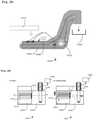
- FIG. 2A is a side sectional view schematically showing a state of a machine side tank in a conventional coolant treatment system including only the machine side tank.
- FIG. 2B is a side sectional view schematically showing a state of the drum filter and the scraper conveyor of the machine side tank shown in FIG. 2A .
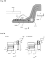
- FIG. 3A is a side sectional view schematically showing a state of a machine side tank in a sludge treatment system according to one embodiment including a machine side tank and a sludge treatment device.
- FIG. 3B is a side sectional view schematically showing a state of the drum filter and the scraper conveyor of the machine side tank shown in FIG. 3A .
- the machine side tank 200 includes a pre-filtration storage unit 220 in which the liquid sent from the machine tool 300 is stored and a post-filtration storage unit 230 in which the liquid filtered by the drum filter 210 is stored.
- a scraper conveyor 240 is disposed in the pre-filtration storage unit 220, and a scraper 242 captures a removal target object C such as chips conveyed together with a liquid and conveys the object to a disposal box 244 by the conveyor for disposal.
- the drum filter 210 also functions as a conveyor wheel of the scraper conveyor 240.
- the filtered liquid stored in the post-filtration storage unit 230 is sent to the sludge treatment device 100 by the primary tank supply pump 162.
- a conventional machine side tank 1200 also has substantially the same configuration as that of the machine side tank 200 according to the present embodiment.
- the conventional machine side tank 1200 is configured to return the liquid filtered by the drum filter 1210 directly to a machine tool 1300. Accordingly, the liquid circulated for use in the machine tool 1300 basically needs to be stored in the machine side tank 1200. Accordingly, as shown in FIGS. 2A and 2B , the liquid level of the liquid in the machine side tank 1200 is always high.
- the removal target object C such as chips floating near the liquid level of the liquid is located above a scraper 1242 of a scraper conveyor 1240. Accordingly, it is difficult for the scraper 1242 to capture the removal target object C. Therefore, the amount of removal target object C such as chips increases in the machine side tank 1200, and the operation becomes difficult with the lapse of time.
- the liquid filtered by the drum filter 210 is sent to the sludge treatment device 100 side by the primary tank supply pump 162. That is, in the sludge treatment system 400 according to the present embodiment, the liquid circulated for use in the machine tool 300 can be stored not only in the machine side tank 200 but also in the sludge treatment device 100. Therefore, as shown in FIGS. 3A and 3B , in the machine side tank 200 according to the present embodiment, the liquid level of the liquid can be lowered.
- a larger region of the outer peripheral surface of the drum filter 210 can be positioned above the liquid level of the liquid. Accordingly, when the liquid is discharged from a backwashing nozzle 212 and backwashing of the drum filter 210 is performed, much of the liquid for backwashing can be caused to flow out from the filtration surface into the atmosphere, so that the substance attached on the filtration surface can be more effectively removed. This makes it possible to suppress the deterioration of filtration performance.
- the removal target object C such as chips floating near the liquid level of the liquid can be captured by the scraper 242 of the scraper conveyor 240. This makes it possible to sufficiently remove the removal target object C such as chips that has entered the machine side tank 200 together with the liquid.
- the amount of liquid that can be stored in a primary tank 110 and a secondary tank 120 provided in the sludge treatment device 100 is larger than the amount of liquid that can be stored in the machine side tank 200. This makes it possible to reliably lower the liquid level of the liquid in the machine side tank 200.
- the liquid is filtered by the drum filter 210, but the present invention is not limited thereto.
- the liquid can be filtered using any known filter or filtration device.
- a main body 2 for storing liquid is partitioned by a partition portion 4 to form the primary tank 110 into which liquid flows from the machine tool 300 side and the secondary tank 120 from which liquid inside flows out to the machine tool 300 side.
- the sludge treatment device 100 further includes a first flow path 130 for supplying liquid in the primary tank 110 to the secondary tank 120.
- the liquid in the machine side tank 200 is supplied to the primary tank 110 via a primary tank supply flow path 160 by the primary tank supply pump 162.
- the liquid in the primary tank 110 is supplied to the secondary tank 120 via the first flow path 130 by the first flow path pump.
- the liquid in the secondary tank 120 is returned to the machine tool 300 via a return flow path 170 by a return pump 172.
- the liquid supplied from the machine side tank 200 to the primary tank 110 is filtered by the drum filter 210, but contains fine sludge and the like.
- a filter 134 is provided on the first flow path 130 that supplies the liquid in the primary tank 110 to the secondary tank 120.
- a cyclone filter is used as the filter 134. The filter 134 removes fine sludge contained in the liquid and supplies a clean liquid to the secondary tank 120. The clean liquid in the secondary tank 120 is returned to the machine tool 300 via the return flow path 170.
- the filter 134 used in the present embodiment is not limited to the cyclone filter, and any known filter that can remove fine sludge can be adopted.
- the filter 134 disposed on the first flow path 130 can remove the fine sludge contained in the liquid in the primary tank 110 and supply the filtered liquid to the secondary tank 120.
- finer sludge passing through the mesh of the filter 134 may flow into the secondary tank 120.
- the possibility of clogging the nozzle or the like of the machine tool 300 cannot be denied.
- the finer sludge that has passed through the filter 134 gradually aggregates in the secondary tank 120. It is considered that the flocculated sludge is accumulated in the lower portion of the secondary tank 120 by gravity. Such flocculated sludge is considered to have a size that can be removed by the filter 134.
- the liquid in the lower portion in the secondary tank 120 can be returned to the primary tank 110 using a second flow path 140 different from the first flow path 130 connecting the primary tank 110 and the secondary tank 120.
- This makes it possible to return the flocculated sludge accumulated in the lower portion existing in the secondary tank 120 to the primary tank 110.
- the flocculated sludge returned to the primary tank 110 is sucked again into the first flow path 130 together with the liquid and removed by the filter 134 in the first flow path 130. Repeating this cycle can reduce the amount of finer sludge in the liquid and prevent clogging of nozzles and the like in the machine tool 300.
- the sludge treatment device 100 includes a liquid inflow amount adjustment means 142 that adjusts the inflow amount of liquid flowing from the secondary tank 120 into the primary tank 110 through the second flow path 140.
- a liquid inflow amount adjustment means 142 an on-off valve that opens and closes the second flow path 140 by a signal from the control unit is used.
- the on-off valve (liquid inflow amount adjustment means) 142 is opened in a state in which a liquid level H2 of the secondary tank 120 is higher than a liquid level H1 of the primary tank 110, the liquid can be returned from the secondary tank 120 to the primary tank 110 by a so-called siphon principle. This makes it possible to reliably return the flocculated sludge accumulated in the lower portion in the secondary tank 120 to the primary tank 110.
- the sludge treatment device 100 that can remove fine sludge in a liquid with a simple structure.
- the on-off valve (liquid inflow amount adjustment means) 142 is opened in a state in which the liquid level H2 of the secondary tank 120 is higher than the liquid level H1 of the primary tank 110. This can reliably return the flocculated sludge accumulated in the lower part in the secondary tank 120 to the primary tank 110.
- the sludge treatment device 100 is provided with a primary tank level meter S1 that detects the liquid level H1 of the primary tank 110 and a secondary tank level meter S2 that detects the liquid level H2 of the secondary tank 120.
- a bottom surface 8 of the secondary tank 120 is an inclined surface.
- the precipitated flocculated sludge is likely to gather in a lower region of the inclined bottom surface 8 due to gravity.
- an inlet 140A of the second flow path 140 is disposed in the lower region of the inclined bottom surface 8, the flocculated sludge easily flows into the first flow path 130 together with the liquid.
- an outlet 130B of the first flow path 130 to which the liquid having passed through the filter 134 is supplied is disposed in the lower region of the inclined bottom surface 8. Accordingly, the flocculation sludge is easily formed in the lower region of the inclined bottom surface 8.
- the bottom surface 8 of the secondary tank 120 is an inclined surface.
- the present invention is not limited thereto.
- the flocculated sludge easily flows into the first flow path 130. This makes it possible to reliably return the flocculated sludge accumulated in the lower portion in the secondary tank 120 to the primary tank 110 via the second flow path 140.
- the second flow path 140 is connected to the lower portion of the primary tank 110. Accordingly, the flocculated sludge returning to the primary tank 110 can be effectively sucked into the first flow path 130 and removed by the filter 134.
- an inlet 130A of the first flow path 130 is preferably disposed near an outlet 140B of the second flow path 140.
- a bottom surface 6 of the primary tank 110 is also an inclined surface, and the outlet 140B of the second flow path 140 is disposed in a lower region of the inclined bottom surface 6.
- a Y-shaped joint 144 is provided in the middle of the second flow path 140, to which a second flow path liquid supply path 150 into which the liquid in the primary tank 110 flows is connected.
- the Y-shaped joint 144 is attached in an inclined state so as to inject a liquid from the secondary tank 120 toward the primary tank 110.
- the second flow path liquid supply path 150 is branched from and connected to the first flow path 130.
- the second flow path liquid supply path 150 is provided with an on-off valve 152 that opens and closes the second flow path liquid supply path 150 based on a signal from the control unit.
- This generates a so-called ejector effect and can promote the flow from the secondary tank 120 to the primary tank 110 in the second flow path 140. This makes it possible to more effectively return the flocculated sludge accumulated in the lower portion in the secondary tank 120 to the primary tank 110.
- the flow in the second flow path 140 can be promoted by applying an ejector effect by the second flow path liquid supply path 150. Control processing related to these will be described in detail later.
- the second flow path liquid supply path 150 is branched from and connected to the first flow path 130.
- the present invention is not limited thereto.
- the present invention can also be provided with an individual flow path including a pump dedicated to the second flow path liquid supply path 150. Even in this case, a large ejector effect can be obtained only by using a very small pump.
- FIG. 4 is a block diagram showing the control unit of the sludge treatment device according to one embodiment of the present disclosure.
- a control unit 50 of the sludge treatment device 100 includes a pump control unit 52 that controls the first flow path pump 132, the primary tank supply pump 162, and a return pump 172 and a liquid inflow amount adjustment means control unit 54 that controls the flow rate in the second flow path 140.
- the liquid inflow amount adjustment means control unit 54 controls the on-off valve (liquid inflow amount adjustment means) 142 and the on-off valve 152 based on, for example, signals received from the primary tank level meter S1 that detects the liquid level H1 in the primary tank 110 and the secondary tank level meter S2 that detects the liquid level H2 in the secondary tank 120.
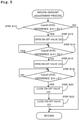
- FIG. 5 is a flowchart illustrating an example of control processing in a liquid inflow amount adjustment means control unit.
- the liquid inflow amount adjustment means control unit 54 performs control for adjusting the liquid inflow amount in the second flow path 140 based on the liquid level H1 of the primary tank 110 and the liquid level H2 of the secondary tank 120.
- the liquid inflow amount adjustment means control unit 54 first determines whether the head difference ⁇ H is larger than the first reference value D1 (step S12).
- the first reference value D1 indicates a reference head difference for determining whether the liquid reliably flows from the secondary tank 120 to the primary tank 110 in the first flow path 130.
- step S10 If it is determined in the determination of step S10 that a head difference ⁇ H is equal to or less than a first reference value D1 (NO), this control process ends as it is.
- the liquid inflow amount adjustment means control unit 54 Upon determining in step S10 that the head difference ⁇ H is larger than the first reference value D1 (YES), the liquid inflow amount adjustment means control unit 54 sends a signal to the on-off valve (liquid inflow amount adjustment means) 142 to change the on-off valve (liquid inflow amount adjustment means) 142 from the closed state to the open state (S12).
- the liquid flows from the secondary tank 120 to the primary tank 110 in the first flow path 130 according to the principle of siphon.
- the second reference value D2 has a value larger than the first reference value D1 and indicates a reference head difference for determining whether or not it is necessary to assist the flow by the ejector effect.
- the liquid inflow amount adjustment means control unit 54 Upon determining in the determination of step S14 that the head difference ⁇ H is equal to or less than the second reference value D2 (NO), the liquid inflow amount adjustment means control unit 54 sends a signal to the on-off valve 152 to change the on-off valve from the closed state to the open state (S16).
- the liquid in the primary tank 110 flows through the second flow path liquid supply path 150 and flows into the second flow path 140 from the middle of the second flow path 140.
- the flow of liquid in the second flow path 140 is promoted based on the ejector effect.
- the on-off valve 152 is opened from the beginning of the flow.
- step S14 when it is determined in step S14 that the head difference ⁇ H is larger than the second reference value D2 (YES), that is, when there is the head difference ⁇ H by which a predetermined flow can be obtained without assistance by the ejector effect at the time of starting the flow of the liquid in the second flow path 140, this determination process is repeated. Then, when the liquid flows in the first flow path 130 from the secondary tank 120 to the primary tank 110, the head difference ⁇ H between the primary tank 110 and the secondary tank 120 decreases to a value equal to or less than the second reference value D2, the on-off valve 152 is opened to start assisting the flow of the liquid in the second flow path 140 by the ejector effect.
- the present invention is not limited to this control process, and even when the head difference ⁇ H is larger than the second reference value D2, the on-off valve 152 can be opened to add assistance by the ejector effect. In this case, the liquid in the secondary tank can be returned to the primary tank 110 more quickly.
- step S18 It is then determined whether the head difference ⁇ H has reached 0 (step S18). In this determination, when it is determined that ⁇ H has not yet reached 0 (NO), this determination processing is repeated. If it is determined in step S18 that the head difference ⁇ H has reached 0 (YES), the on-off valve (liquid inflow amount adjustment means) 142 is closed (step S20), the on-off valve 152 is closed (step S24), and the control process is terminated.
- liquid inflow amount adjustment means control unit 54 controls opening and closing of the on-off valve (liquid inflow amount adjustment means) 142 and the on-off valve 152 based on the liquid level H1 of the primary tank 110 and the liquid level H2 of the secondary tank 120, it is possible to reliably return the flocculated sludge in the secondary tank 120 to the primary tank 110.
- the liquid inflow amount adjustment means control unit 54 performs control for adjusting the liquid inflow amount in the second flow path 140 based on the liquid level H1 of the primary tank 110 and the liquid level H2 of the secondary tank 120.
- the present invention is not limited thereto.
- the liquid inflow amount adjustment means control unit 54 can also perform control for adjusting the liquid inflow amount in the second flow path 140 based on the elapsed time without using the liquid levels of the primary tank 110 and the secondary tank 120.
- the liquid inflow amount adjustment means control unit 54 controls opening and closing of the on-off valve (liquid inflow amount adjustment means) 142 and the on-off valve 152 based on the elapsed time.
- control based on the elapsed time is performed.
- a plurality of control patterns based on the elapsed times are provided according to the operation patterns of the first flow path pump 132, the primary tank supply pump 162, and the return pump 172, and an optimum control pattern can be selected in accordance with the situation.
- the liquid inflow amount adjustment means control unit 54 performs control for adjusting the liquid inflow amount in the second flow path 140 based on the elapsed time. This makes it possible to return the flocculated sludge in the secondary tank 120 to the primary tank 110 by simple control without requiring a special sensor or the like.
- the flow rate of liquid flowing in the first flow path 130 may be larger than the flow rate of liquid flowing from the secondary tank 120 to the machine tool 300 side by the return flow path 170.
- the level of liquid in the secondary tank 120 increases. Accordingly, when a large amount of liquid is circulated, it is necessary to increase the capacity of the secondary tank 120. This makes it difficult to reduce the size of the sludge treatment device 100.
- the liquid in the secondary tank 120 can be returned to the primary tank 110 side using the second flow path 140, and the liquid level of the liquid in the secondary tank 120 can be lowered. This makes it possible to obtain substantially the same effect as that obtained by increasing the liquid capacity of the secondary tank 120 and downsize the sludge treatment device 100.
- FIG. 6 is a diagram schematically showing a sludge treatment system according to another embodiment of the present disclosure.
- FIG. 7 is a block diagram showing the control unit of the sludge treatment device according to another embodiment of the present disclosure.
- the on-off valve 142 is provided as a liquid inflow amount adjustment means, and the flow of the second flow path 140 is formed using the principle of siphon.
- the present embodiment is different in that a second flow path pump 146 is provided as a liquid inflow amount adjustment means, and the flow of the second flow path 140 is formed by the discharge force of the second flow path pump (liquid inflow amount adjustment means) 146.
- the liquid flows from the secondary tank 120 to the primary tank 110 in the second flow path 140 by the second flow path pump (liquid inflow amount adjustment means) 146.
- the inlet (suction port of the pump) 140A of the second flow path 140 is disposed in the lower portion of the secondary tank 120 where flocculated sludge tends to accumulate.
- the liquid since the liquid flows by the discharge force of the second flow path pump (liquid inflow amount adjustment means) 146, the liquid can flow from the secondary tank 120 to the primary tank 110 even in a state in which the liquid level H2 of the secondary tank 120 is not higher than the liquid level H1 of the primary tank 110. In the present embodiment, it is not necessary to provide the second flow path liquid supply path 150 that promotes the flow by the ejector effect.
- the liquid inflow amount adjustment means control unit 54 controls driving of the second flow path pump (liquid inflow amount adjustment means) 146 instead of the on-off valve (liquid inflow amount adjustment means) 142 and the on-off valve 152. As a result, it is possible to return the flocculated sludge in the secondary tank 120 to the primary tank 110 while adjusting the liquid levels of the secondary tank 110 and the primary tank 120.
- the main body 2 is partitioned by the partition portion 4 to form the primary tank 110 and the secondary tank 120.
- the primary tank and the secondary tank may be separate members each having an individual main body. In this case, setting the installation position of the secondary tank higher than the installation position of the primary tank can easily obtain the flow of the liquid in the second flow path according to the principle of siphon.
Landscapes
- Chemical & Material Sciences (AREA)
- Chemical Kinetics & Catalysis (AREA)
- Engineering & Computer Science (AREA)
- Mechanical Engineering (AREA)
- Life Sciences & Earth Sciences (AREA)
- Hydrology & Water Resources (AREA)
- Environmental & Geological Engineering (AREA)
- Water Supply & Treatment (AREA)
- Organic Chemistry (AREA)
- Treatment Of Sludge (AREA)
- Filtration Of Liquid (AREA)
- Auxiliary Devices For Machine Tools (AREA)
Applications Claiming Priority (2)
| Application Number | Priority Date | Filing Date | Title |
|---|---|---|---|
| JP2019116350A JP6738942B1 (ja) | 2019-06-24 | 2019-06-24 | スラッジの処理装置及びスラッジ処理システム工作機械 |
| PCT/JP2020/021789 WO2020261896A1 (fr) | 2019-06-24 | 2020-06-02 | Dispositif de traitement de boue et machine de travail de système de traitement de boue |
Publications (2)
| Publication Number | Publication Date |
|---|---|
| EP3967384A1 true EP3967384A1 (fr) | 2022-03-16 |
| EP3967384A4 EP3967384A4 (fr) | 2023-02-08 |
Family
ID=71949309
Family Applications (1)
| Application Number | Title | Priority Date | Filing Date |
|---|---|---|---|
| EP20831778.4A Withdrawn EP3967384A4 (fr) | 2019-06-24 | 2020-06-02 | Dispositif de traitement de boue et machine de travail de système de traitement de boue |
Country Status (5)
| Country | Link |
|---|---|
| US (1) | US20220111477A1 (fr) |
| EP (1) | EP3967384A4 (fr) |
| JP (1) | JP6738942B1 (fr) |
| CN (1) | CN114025861B (fr) |
| WO (1) | WO2020261896A1 (fr) |
Families Citing this family (3)
| Publication number | Priority date | Publication date | Assignee | Title |
|---|---|---|---|---|
| JP6375424B1 (ja) * | 2017-09-13 | 2018-08-15 | 株式会社ブンリ | 濾過装置 |
| US20200078894A1 (en) * | 2018-09-07 | 2020-03-12 | Manufacturing Productivity Systems | Coolant filtration system |
| JP7495147B2 (ja) | 2022-08-24 | 2024-06-04 | 榎本ビーエー株式会社 | 切粉濾過装置 |
Family Cites Families (18)
| Publication number | Priority date | Publication date | Assignee | Title |
|---|---|---|---|---|
| US4396506A (en) * | 1981-08-27 | 1983-08-02 | Pecor Corporation | Liquid clarifier and method |
| JPH0396153U (fr) * | 1990-01-24 | 1991-10-01 | ||
| JP2725127B2 (ja) * | 1992-11-26 | 1998-03-09 | 三栄技研株式会社 | 歯科治療汚物の廃水処理装置 |
| JP3009783U (ja) * | 1994-09-30 | 1995-04-11 | 株式会社シイエヌケイ | 渦流式クーラント液の清浄装置 |
| DE10043418A1 (de) * | 2000-09-04 | 2002-04-18 | Hilti Ag | Kühl- und Spülvorrichtung für Werkzeuge zur Bearbeitung von Gestein |
| US7311744B2 (en) * | 2001-08-15 | 2007-12-25 | Elliott Michael R | Cyclonic separator for mist collectors |
| JP2005219201A (ja) * | 2004-01-08 | 2005-08-18 | Nikuni:Kk | ワイヤカット放電加工用液処理装置 |
| KR100692710B1 (ko) * | 2005-07-01 | 2007-03-09 | 현대자동차주식회사 | 가공기계용 쿨런트 순환시스템 |
| CN101516570B (zh) * | 2006-09-21 | 2012-04-04 | 住友重机械精科技株式会社 | 工作机械用冷却液净化装置 |
| WO2009153980A1 (fr) * | 2008-06-16 | 2009-12-23 | 岡野機工株式会社 | Dispositif de séparation de particules magnétiques et système de purification d’un fluide à traiter |
| PE20140602A1 (es) * | 2010-12-13 | 2014-05-13 | Smidth As F L | Sistema de disolucion de alimentacion de canal abierto para un espesador o tanque de sedimentacion |
| JP2013169534A (ja) * | 2012-02-22 | 2013-09-02 | Aisin Ai Co Ltd | スクリューコンベア及びエア駆動ポンプ装置を使用した濾過装置 |
| JP5930938B2 (ja) * | 2012-10-30 | 2016-06-08 | 株式会社ジェイテクト | クーラントシステム |
| US9770804B2 (en) * | 2013-03-18 | 2017-09-26 | Versum Materials Us, Llc | Slurry supply and/or chemical blend supply apparatuses, processes, methods of use and methods of manufacture |
| TWI606884B (zh) * | 2016-01-29 | 2017-12-01 | 慶鴻機電工業股份有限公司 | 金屬加工機之回收液處理設備及其方法 |
| CN207171643U (zh) * | 2017-08-10 | 2018-04-03 | 山东豪迈机械科技股份有限公司 | 一种切削液净化装置 |
| JP6375424B1 (ja) * | 2017-09-13 | 2018-08-15 | 株式会社ブンリ | 濾過装置 |
| JP7235664B2 (ja) * | 2017-09-20 | 2023-03-08 | 住友重機械ファインテック株式会社 | クーラント液処理システム及びフロート式逆止弁 |
-
2019
- 2019-06-24 JP JP2019116350A patent/JP6738942B1/ja not_active Expired - Fee Related
-
2020
- 2020-06-02 WO PCT/JP2020/021789 patent/WO2020261896A1/fr not_active Ceased
- 2020-06-02 CN CN202080046181.5A patent/CN114025861B/zh not_active Expired - Fee Related
- 2020-06-02 EP EP20831778.4A patent/EP3967384A4/fr not_active Withdrawn
-
2021
- 2021-12-23 US US17/561,644 patent/US20220111477A1/en not_active Abandoned
Also Published As
| Publication number | Publication date |
|---|---|
| CN114025861A (zh) | 2022-02-08 |
| CN114025861B (zh) | 2022-12-30 |
| EP3967384A4 (fr) | 2023-02-08 |
| US20220111477A1 (en) | 2022-04-14 |
| WO2020261896A1 (fr) | 2020-12-30 |
| JP2021000705A (ja) | 2021-01-07 |
| JP6738942B1 (ja) | 2020-08-12 |
Similar Documents
| Publication | Publication Date | Title |
|---|---|---|
| US20220111477A1 (en) | Sludge treatment device and sludge treatment system | |
| KR101205299B1 (ko) | 공작기계용 쿨런트액 정화장치 | |
| EP3395498B1 (fr) | Dispositif de filtration | |
| US3455062A (en) | Abrasive blast system with closed circuit rinse | |
| KR20220133347A (ko) | 공작기계의 절삭유 미세 칩 여과 장치 | |
| CN113001412B (zh) | 磨床用磨削液过滤装置 | |
| JP4878252B2 (ja) | ベルト型濃縮機 | |
| KR100644241B1 (ko) | 절삭유의 칩 여과 장치 및 그 역세척 방법 | |
| CN105848827A (zh) | 冷却剂再生装置以及冷却剂再生方法 | |
| CN113001411B (zh) | 磨床用磨削液过滤装置 | |
| CN113001408A (zh) | 磨床用磨削液过滤装置 | |
| JP2004268244A (ja) | クーラント清浄装置 | |
| JP2008012603A (ja) | クーラント浄化装置 | |
| JP2023060193A (ja) | 軟水化システムおよび軟水化装置 | |
| JP6699346B2 (ja) | バラスト水処理装置 | |
| JPH06115409A (ja) | 洗車装置用給水ユニット | |
| JP2002264015A (ja) | 研削液回収装置 | |
| JP3090347B2 (ja) | 電気めっき液の懸濁物処理方法 | |
| KR102641918B1 (ko) | 분뇨 및 가축분뇨 처리시설 탈리여액 여과장치 | |
| JP4758743B2 (ja) | 液中の固形分分離除去装置 | |
| CN117140170B (zh) | 冷却剂处理装置 | |
| JP3047545U (ja) | クーラントタンク内の砥粒を含むスラッジの堆積防止装置 | |
| JP3459108B2 (ja) | セメント系スラリー等の固化性成分を含有する汚水の濾過装置 | |
| JP3026176B2 (ja) | 粉塵処理装置 | |
| WO2024247456A1 (fr) | Système et procédé d'ajout |
Legal Events
| Date | Code | Title | Description |
|---|---|---|---|
| STAA | Information on the status of an ep patent application or granted ep patent |
Free format text: STATUS: THE INTERNATIONAL PUBLICATION HAS BEEN MADE |
|
| PUAI | Public reference made under article 153(3) epc to a published international application that has entered the european phase |
Free format text: ORIGINAL CODE: 0009012 |
|
| STAA | Information on the status of an ep patent application or granted ep patent |
Free format text: STATUS: REQUEST FOR EXAMINATION WAS MADE |
|
| 17P | Request for examination filed |
Effective date: 20211208 |
|
| AK | Designated contracting states |
Kind code of ref document: A1 Designated state(s): AL AT BE BG CH CY CZ DE DK EE ES FI FR GB GR HR HU IE IS IT LI LT LU LV MC MK MT NL NO PL PT RO RS SE SI SK SM TR |
|
| DAV | Request for validation of the european patent (deleted) | ||
| DAX | Request for extension of the european patent (deleted) | ||
| A4 | Supplementary search report drawn up and despatched |
Effective date: 20230109 |
|
| RIC1 | Information provided on ipc code assigned before grant |
Ipc: C02F 1/38 19800101ALN20230103BHEP Ipc: C02F 1/00 19800101ALN20230103BHEP Ipc: C02F 103/34 20000101ALN20230103BHEP Ipc: B01D 33/073 19900101ALI20230103BHEP Ipc: B01D 33/50 19900101ALI20230103BHEP Ipc: B01D 33/76 19900101ALI20230103BHEP Ipc: B01D 33/80 19900101ALI20230103BHEP Ipc: C02F 11/126 20190101ALI20230103BHEP Ipc: B23Q 11/10 19680901ALI20230103BHEP Ipc: B23Q 11/00 19680901ALI20230103BHEP Ipc: B01D 36/02 19850101ALI20230103BHEP Ipc: B01D 33/06 19680901AFI20230103BHEP |
|
| STAA | Information on the status of an ep patent application or granted ep patent |
Free format text: STATUS: THE APPLICATION IS DEEMED TO BE WITHDRAWN |
|
| 18D | Application deemed to be withdrawn |
Effective date: 20230808 |