EP3967389B1 - Hohlfasermembrankomponente mit externem druck, filtrationsmembrankomponente und membranfiltrationsmodul - Google Patents
Hohlfasermembrankomponente mit externem druck, filtrationsmembrankomponente und membranfiltrationsmodul Download PDFInfo
- Publication number
- EP3967389B1 EP3967389B1 EP20876255.9A EP20876255A EP3967389B1 EP 3967389 B1 EP3967389 B1 EP 3967389B1 EP 20876255 A EP20876255 A EP 20876255A EP 3967389 B1 EP3967389 B1 EP 3967389B1
- Authority
- EP
- European Patent Office
- Prior art keywords
- housing
- hollow fiber
- fiber membrane
- passage
- passages
- Prior art date
- Legal status (The legal status is an assumption and is not a legal conclusion. Google has not performed a legal analysis and makes no representation as to the accuracy of the status listed.)
- Active
Links
Images




Classifications
-
- C—CHEMISTRY; METALLURGY
- C02—TREATMENT OF WATER, WASTE WATER, SEWAGE, OR SLUDGE
- C02F—TREATMENT OF WATER, WASTE WATER, SEWAGE, OR SLUDGE
- C02F1/00—Treatment of water, waste water, or sewage
- C02F1/44—Treatment of water, waste water, or sewage by dialysis, osmosis or reverse osmosis
- C02F1/444—Treatment of water, waste water, or sewage by dialysis, osmosis or reverse osmosis by ultrafiltration or microfiltration
-
- B—PERFORMING OPERATIONS; TRANSPORTING
- B01—PHYSICAL OR CHEMICAL PROCESSES OR APPARATUS IN GENERAL
- B01D—SEPARATION
- B01D63/00—Apparatus in general for separation processes using semi-permeable membranes
- B01D63/02—Hollow fibre modules
-
- B—PERFORMING OPERATIONS; TRANSPORTING
- B01—PHYSICAL OR CHEMICAL PROCESSES OR APPARATUS IN GENERAL
- B01D—SEPARATION
- B01D63/00—Apparatus in general for separation processes using semi-permeable membranes
- B01D63/02—Hollow fibre modules
- B01D63/033—Specific distribution of fibres within one potting or tube-sheet
-
- B—PERFORMING OPERATIONS; TRANSPORTING
- B01—PHYSICAL OR CHEMICAL PROCESSES OR APPARATUS IN GENERAL
- B01D—SEPARATION
- B01D63/00—Apparatus in general for separation processes using semi-permeable membranes
- B01D63/02—Hollow fibre modules
- B01D63/04—Hollow fibre modules comprising multiple hollow fibre assemblies
-
- B—PERFORMING OPERATIONS; TRANSPORTING
- B01—PHYSICAL OR CHEMICAL PROCESSES OR APPARATUS IN GENERAL
- B01D—SEPARATION
- B01D65/00—Accessories or auxiliary operations, in general, for separation processes or apparatus using semi-permeable membranes
- B01D65/02—Membrane cleaning or sterilisation ; Membrane regeneration
-
- B—PERFORMING OPERATIONS; TRANSPORTING
- B01—PHYSICAL OR CHEMICAL PROCESSES OR APPARATUS IN GENERAL
- B01D—SEPARATION
- B01D2313/00—Details relating to membrane modules or apparatus
- B01D2313/20—Specific housing
-
- B—PERFORMING OPERATIONS; TRANSPORTING
- B01—PHYSICAL OR CHEMICAL PROCESSES OR APPARATUS IN GENERAL
- B01D—SEPARATION
- B01D2313/00—Details relating to membrane modules or apparatus
- B01D2313/21—Specific headers, end caps
-
- B—PERFORMING OPERATIONS; TRANSPORTING
- B01—PHYSICAL OR CHEMICAL PROCESSES OR APPARATUS IN GENERAL
- B01D—SEPARATION
- B01D2321/00—Details relating to membrane cleaning, regeneration, sterilization or to the prevention of fouling
- B01D2321/18—Use of gases
- B01D2321/185—Aeration
-
- B—PERFORMING OPERATIONS; TRANSPORTING
- B01—PHYSICAL OR CHEMICAL PROCESSES OR APPARATUS IN GENERAL
- B01D—SEPARATION
- B01D69/00—Semi-permeable membranes for separation processes or apparatus characterised by their form, structure or properties; Manufacturing processes specially adapted therefor
- B01D69/08—Hollow fibre membranes
Definitions
- the present disclosure relates to the field of membrane filtration separation, in particular to an external pressure type hollow fiber membrane assembly, a filtration membrane assembly and a membrane filtration module.
- Membrane separation technology has been widely used in fields such as water purification treatment or liquid filtration separation.
- hollow fiber membrane assemblies are classified into two types according to different filtration directions: an internal pressure type and an external pressure type.
- an internal pressure type When the external pressure type hollow fiber membrane assembly is working, raw water arrives at the outside of the hollow fiber membrane in the pressure housing, and then passes through the hollow fiber membrane to the inner cavity of the hollow fiber membrane to form a filtrate, wherein pollutants are trapped at the outside of the hollow fiber membrane.
- the external pressure type hollow fiber membrane assembly may be used for raw water containing high concentration of pollutants.
- a gas transmission passage is usually provided at the lower end of the filtration membrane assembly to drive the filtered dirt or large particulate matter with air pressure to avoid separation from the filtration membrane.
- a gas transmission passage is usually provided at the lower end of the filtration membrane assembly to drive the filtered dirt or large particulate matter with air pressure to avoid separation from the filtration membrane.
- DE 10 2013 218208 A1 describes an external pressure type hollow fiber membrane assembly comprising a housing having an inner chamber and one end member provided at one end of the inner of the housing wherein the end member is provided with a plurality of void passages extending through the end member along an axial direction of the housing, and a plurality of water collection passages, wherein the void passages and the water collection passages are provided alternately.
- Patent documents EP 0 947 237 A1 , WO 2012/134127 A2 , US 8 372 282 B2 describe a filtration membrane assembly comprising a housing which includes an inner chamber and a first end and a second end opposite to each other, and a first end cap hermetically fixedly connected to the first end of the housing, wherein the first end cap has a gas transmission passage which communicates with the inner chamber of the housing and opens at both sides.
- an external pressure type hollow fiber membrane assembly comprising:
- both of the two end members are provided with void passages, so that raw water or aeration gas can be smoothly discharged from the inner chamber of the housing.
- pollutants at an outside of hollow fiber membrane filaments can flow out of the void passages conveniently, thereby avoiding unduly accumulation of pollutants at the roots of the hollow fiber membrane filaments.
- the filtration energy consumption of the external pressure type hollow fiber membrane assembly can be reduced while the filtration efficiency of the external pressure type hollow fiber membrane assembly is guaranteed.
- an extending direction of the void passage is a straight line, and a plurality of the void passages are parallel to each other.
- the external pressure type hollow fiber membrane assembly further comprises a plurality of hollow fiber membrane bundles provided in the inner chamber of the housing; and the hollow fiber membrane bundles have a width of less than or equal to 60 mm.
- a ratio of a width of the water collection passage to a width of the void passage is less than 6.
- the external pressure type hollow fiber membrane assembly further comprises a plurality of hollow fiber membrane bundles provided in the inner chamber of the housing, wherein in a direction perpendicular to an axial direction of the housing, the hollow fiber membrane bundle has a cross section that is circular and has an outer diameter of less than 60mm.
- the void passage in a direction perpendicular to an axial direction of the housing, has a cross section that is fan-shaped or annular-sector-shaped.
- a cross-sectional area of the void passage perpendicular to an axial direction of the housing decreases gradually from outside to inside in an axial direction of the housing.
- the external pressure type hollow fiber membrane assembly further comprises a first end cap hermetically connected to an end of the housing, and a pulse aerator is provided at a side of the first end cap proximal to the inner chamber of the housing.
- the pulse aerator has a gas stream release hole proximal to the end member, and the gas stream release hole is coaxial with the pulse aerator.
- the present disclosure further provides a filtration device comprising the external pressure type hollow fiber membrane assembly provided by the present disclosure.
- both of the two end members are provided with void passages, so that raw water or aeration gas can be smoothly discharged from the inner chamber of the housing.
- pollutants at an outside of hollow fiber membrane filaments can flow out of the void passages conveniently, thereby avoiding unduly accumulation of pollutants at the roots of the hollow fiber membrane filaments.
- the filtration energy consumption of the external pressure type hollow fiber membrane assembly can be reduced while the filtration efficiency of the external pressure type hollow fiber membrane assembly is guaranteed.
- the present disclosure further provides a filtration membrane assembly, comprising:
- the gas transmission passages of adjacent filtration membrane assemblies are connected to exempt necessity to provide a separate gas transmission pipeline for each filtration membrane assembly.
- the assembled membrane filtration module has a simple structure and occupies a small space.
- the first end cap further has a first water stream passage which communicates with the inner chamber of the housing and opens at both sides, wherein the first water stream passage can be joined end-to-end to a water stream passage of another filtration membrane assembly;
- the filtration membrane assembly further comprises a connection assembly which can be removably connected to both an opening of the gas transmission passage and an opening of the first water stream passage.
- connection assembly comprises two double-orifice hoop halves which can be removably joined end-to-end, wherein, after the two double-orifice hoop halves are joined end-to-end, two orifices are formed for connection to the opening of the gas transmission passage and the opening of the first water stream passage respectively.
- an outer side wall of the gas transmission passage proximal to one of the openings forms a first abutting section
- an outer side wall of the gas transmission passage proximal to the other of the openings forms a second abutting section.
- the filtration membrane assembly further comprises a second end cap which is hermetically, fixedly connected to the second end of the housing, wherein the first end cap is hermetically connected to the housing with a hermetic connection assembly, and/or the second end cap is hermetically connected to the housing with a hermetic connection assembly; the first end cap and the second end cap each have a connection section which can be sleeved on the housing, wherein an outer surface of the connection section is provided with an external thread.
- the hermetic connection assembly comprises:
- the abutting surface of the threaded sleeve is a tapered surface; the anti-dropping piece is in a shape of a broken loop; an inner surface of the anti-dropping piece is a tooth surface; and the anti-dropping piece has a hardness greater than that of the housing.
- the hermetic connection assembly further comprises a second sealing ring provided between the housing and the connection section of the first end cap or the connection section of the second end cap.
- the hermetic connection assembly further comprises a stopper sleeved on the housing; an inner surface of the connection section of the first end cap has a first limit face; the stopper has a second limit face disposed opposite to the first limit face; the second limit face is not parallel to an axial direction of the housing; both ends of the second sealing ring abut against the first limit face and the second limit face; an end of the stopper distal from the second sealing ring abuts against the anti-dropping piece.
- the filtration membrane assembly further comprises a hollow fiber membrane and a second end cap hermetically, fixedly connected to the second end of the housing, wherein the second end cap is provided with a second water stream passage and a purified water stream passage, wherein the second water stream passage communicates with an outside of the hollow fiber membrane; wherein the membrane filtration module further comprises a pressurizing pipeline in communication with the second water stream passage, wherein a spacing between the pressurizing pipeline and the second end of the housing is greater than a spacing between the purified water stream passage and the second end of the housing.
- the hollow fiber membrane is the external pressure type hollow fiber membrane assembly provided in the present disclosure.
- the present disclosure further provides a membrane filtration module, comprising:
- the above-mentioned membrane filtration module facilitates connection of the gas transmission passages of adjacent filtration membrane assemblies, and thus exempts necessity to provide a gas transmission pipeline for each filtration membrane assembly separately.
- the assembled membrane filtration module has a simple structure and occupies a small space.
- an external pressure type hollow fiber membrane assembly 100-1 provided according to an embodiment of the present invention comprises a housing 110-1 having an inner chamber 111-1, and an end member 130-1.
- the end member 130-1 is provided at an end of the inner chamber 111-1 of the housing 110-1.
- the end member 130-1 is provided with a plurality of void passages 131-1 extending through the end member 130-1 in an axial direction of the housing 110-1 and a plurality of water collection passages 133-1 in communication with each other.
- the void passages 131-1 and the water collection passages 133-1 are provided alternately.
- the axial direction of the housing 110-1 is shown by the dashed line in FIG. 1 .
- the void passage 131-1 is used to discharge pollutants at the outside of the hollow fiber membrane filaments, so the width of the void passage 131-1 needs to enable discharge the pollutants at the outside of the hollow fiber membrane filaments.
- a plurality of void passages 131-1 means that the number of the void passages 131-1 is at least two.
- a plurality of water collection passages 133-1 means that the number of the water collection passages 133-1 is also at least two.
- both of the two end members 130-1 are provided with void passages 131-1, so that in the process in which raw water or aeration gas enters the inner chamber of the housing 110-1 and then exits the inner chamber 111-1 of the housing 110, it is input or output through the two ends of the inner chamber 111-1.
- the raw water or aeration gas enters the inner chamber 111-1 of the housing 110-1 or exits the inner chamber 111-1 of the housing 110-1, forced change of the flow direction of the raw water or aeration gas is avoided, so that the raw water or aeration gas can be discharged from the inner chamber of the housing smoothly.
- the void passages 131-1 can facilitate outflow of the pollutants at the outside of the hollow fiber membrane filaments, and unduly accumulation of the pollutants at the roots of the hollow fiber membrane filaments is avoided, thereby reducing the filtration energy consumption of the external pressure type hollow fiber membrane assembly 100-1 while the filtration efficiency of the external pressure type hollow fiber membrane assembly 100-1 is guaranteed.
- the void passages 131-1 of the two end members 130-1 are provided opposite to each other.
- the projections of the void passages 131-1 of the two end members 130-1 on a plane perpendicular to the axial direction of the housing 110-1 overlap. This makes the input and output of the raw water and aeration gas smoother.
- the void passages 131-1 of the two end members 130-1 are not provided completely opposite to each other.
- the inner chamber of the hollow fiber membrane filament communicates with the water collection passage 133-1.
- the void passage 131-1 and the water collection passage 133-1 are alternately provided, that is, the plurality of water collection passages 133-1 are provided with every two of them being spaced.
- each water collection passage 133-1 corresponds to a separate hollow fiber membrane bundle. Therefore, the hollow fiber membrane bundle corresponding to each water collection passage 133-1 is provided independently.
- the end member 130-1 is provided with at least two void passages 131-1, and the void passages 131-1 and the water collection passages 133-1 are provided alternately, thereby increasing the exposed area of the hollow fiber membrane bundles, so that when raw water enters the inner chamber 111-1 of the housing 110-1, or when aeration gas enters the inner chamber 111-1 of the housing 110-1, it can contact the hollow fiber membrane filaments at a larger area, so as to flush out more pollutants on the hollow fiber membrane filaments.
- the exposed area of the hollow fiber membrane bundle is increased to reduce the thickness of the pollutants adhered to the outer surface of the hollow fiber membrane bundle, so that the adhesion of the pollutants has a lower impact on the filtration efficiency of the hollow fiber membrane bundle, which in turn makes the pollutants on the surface of the hollow fiber membrane bundle easier to clean. This saves the cleaning time of the external pressure type hollow fiber membrane assembly 100-1, and further improves the filtration efficiency of the external pressure type hollow fiber membrane assembly 100-1.
- the material of the end member 130-1 is plastic, rubber, stainless steel or resin.
- the end member 130-1 is cast-molded, and at the same time is cast together with the inner wall of the housing 110-1 and the hollow fiber membrane filaments, wherein the end face outlets of the hollow fiber membrane filaments are kept open.
- the external pressure type hollow fiber membrane assembly 100-1 further comprises a water collection pipeline 150-1 in communication with the water collection passages 133-1.
- the filtrate in the inner cavity of a hollow fiber membrane at least partially flows into a water collection passage 133-1, and then flows into the central water collection pipeline 150-1 in communication with the water collection passage 133-1. Then, the filtrate is discharged.
- the end member 130-1 needs to be provided with a structure for connecting the water collection pipeline 150-1, so that the water collection pipeline 150-1 communicates with the water collection passage 133-1.
- the end member 130-1 is provided with a water collection pipeline interface 135-1 which communicates with the water collection passages 133-1 and matches the water collection pipeline 150-1.
- the axis of the collection pipeline interface 135-1 is collinear with the axis of the end member 130-1.
- the axis of the water collection pipeline interface may also be offset from the axis of the end member.
- the end member 130-1 and the housing 110-1 are removably assembled with a hoop.
- the end member 130-1 and the housing 110-1 may also be assembled and connected by bonding or the like.
- both of the two end members 130-1 are provided with water collection passages 133-1, so that the filtrate in the inner cavity of the hollow fiber membrane can flow smoothly into the water collection passages 133-1, facilitating discharge of the filtrate.
- the two end members 130-1 generally have a height difference in a direction perpendicular to the horizontal plane, so that under the action of gravity, the filtrate in the inner cavity of the hollow fiber membrane can flow smoothly to the water collection passages 133-1 of the lower end member 130-1.
- the filtrate in the inner cavity of the hollow fiber membrane can be discharged smoothly into the water collection passages 133-1 of the upper end member 130-1. That is, the filtrate in the inner cavity of the hollow fiber membrane can be discharged from both ends at the same time, thereby increasing the discharge speed of the filtrate from the inner cavity of the hollow fiber membrane, which in turn improves the filtration efficiency of the external pressure type hollow fiber membrane assembly 100-1.
- the extending direction of the void passages 131-1 in a direction perpendicular to the axial direction of the housing 110-1, is a straight line, and a plurality of void passages 131-1 are parallel to each other.
- the extending direction of the void passages 131-1 is the direction of the surface where a void passage 131-1 and a water collection passage 133-1 join, as shown by the direction m-m in Fig. 2 .
- the extending direction of the water collection passages 133-1 is the same as the extending direction of the void passages.
- the structure of the hollow fiber membrane bundles is also configured in accordance with the structure of the water collection passages 133-1. That is, the structure of the hollow fiber membrane bundles also extends along a straight line.
- the external pressure type hollow fiber membrane assembly 100-1 further comprises a plurality of hollow fiber membrane bundles 170-1 provided in the inner chamber 111-1 of the housing 110-1.
- the width d of the hollow fiber membrane bundle 170-1 is less than or equal to 60 mm. If the width of the hollow fiber membrane bundle 170-1 is larger, more pollutants will adhere to the surface of the hollow fiber membrane bundle 170-1.
- a ratio of the width D1 of the water collection passage 133-1 to the width D2 of the void passage 131-1 is less than 6.
- the width D1 of the water collection passage 133-1 is greater than or equal to the width d of the hollow fiber membrane bundle 170-1.
- a ratio of the width d of the hollow fiber membrane bundle 170-1 to the width D2 of the void passage 131-1 is less than 6. Therefore, large pollutants can smoothly pass through the void passage 131-1 and be discharged, avoiding the circumstance in which the void passage 131-1 is blocked by large pollutants that cannot be discharged, and as a result, the external pressure type hollow fiber membrane assembly 100-1 cannot work properly.
- larger bubbles can also pass through the void passage 131-1 smoothly, so as to achieve better cleaning of dirt from the surface of the hollow fiber membrane bundle 170-1.
- a ratio of the width of the water collection passage 133-1 to the width of the void passage 131-1 may be 6, 5.5, 5, 4.5, 4, 3, 2, 1, or 0.5.
- D1 is the width of the water collection passage
- D2 is the width of the void passage.
- Fig. 3 may be referred to for more details.
- the data in Table 1 are measured under the following preconditions: the raw water has a sludge concentration of 14000mg/L; the output of the water produced is 30L/m 2 .h; the water temperature is 25 °C; the size of the end member 130-1 remains unchanged; and the number of the water collection passages 133-1 and the number of the void passages 131-1 remain unchanged.
- the smaller the ratio of the width D1 of the water collection passage 133-1 to the width D2 of the void passage 131-1 the smaller the transmembrane pressure difference.
- the smaller the ratio of the width D1 of the water collection passage 133-1 to the width D2 of the void passage 131-1 is, the fewer pollutants adhere to the outer surface of the hollow fiber membrane bundle 170-1.
- the smaller the ratio of the width D1 of the water collection passage 133-1 to the width D2 of the void passage 131-1 the smaller the width of the water collection passage 133-1, and the larger the width of the void passage 131-1. Therefore, when the width of the hollow fiber membrane bundle 170-1 is smaller, the width of the void passage 133-1 is larger, and the transmembrane pressure difference is smaller, fewer pollutants will adhere to the surface of the hollow fiber membrane bundle 170-1.
- the void passages 131-1 on the end members 130-1 have the same structure and width. It can be understood that in another feasible embodiment, the void passages may also have different widths. Likewise, the void passages may have different structures. For example, rectangular void passages and fan-shaped void passages may coexist on the same end member.
- the external pressure type hollow fiber membrane assembly 100-1 further comprises a first end cap 190-1 hermetically connected to one end of the housing 110-1, and the first end cap 190-1 is provided with a pulse aerator 180-1 at the side proximal to the inner chamber 111-1 of the housing 110-1.
- the air bubbles released by the pulse aerator 180-1 can enter the inner chamber 111-1 of the housing 110-1 directly through the void passages 131-1, thereby enabling better cleaning of the pollutants from the surface of the hollow fiber membrane bundles 170-1.
- the pulse aerator 180-1 emits the gas stream in a pulse mode. Specifically, the pulse aerator 180-1 inputs a gas stream continuously during operation. The pulse aerator 180-1 can accumulate the energy of a continuous gas stream for a certain period of time and then provide instant aeration to form larger bubbles, so that the impact force of the emitted gas stream is greater, thereby further enabling better cleaning of the pollutants from the surface of the hollow fiber membrane bundles 170-1.
- the pulse aerator 180-1 has a gas stream release hole 181-1 proximal to the end member 130-1, and the gas stream release hole 181-1 is coaxial with the pulse aerator 180-1.
- the pulse aerator 180-1 has only one gas stream release hole 181-1, so that the impact bubbles emitted from the gas stream release hole 181-1 are larger, which in turn provides a greater impact on the surface of the hollow fiber membrane bundles 170-1 to achieve better cleaning of the pollutants from the surface of the hollow fiber membrane bundles 170-1.
- the first end cap 190-1 is provided with an opening 191-1 for communicating the gas transmission port 183-1 of the pulse aerator 180-1 with the surroundings.
- the opening may also be used as a gas transmission passage to communicate with the gas transmission port of the pulse aerator.
- the first end cap 190-1 is provided with a water stream passage 193-1 for conveying raw water to or discharging concentrated water from the inner chamber 111-1 of the housing 110-1.
- the configuration of the pulse aerator 180-1 should not block the communication between the water stream passage 193-1 and the inner chamber 111-1 of the housing 110-1, and should enable the raw water to be smoothly conveyed to the inner chamber of the housing 110-1, or the concentrated water to be smoothly discharged from the water stream passage 193-1.
- the structures of the void passage and water collection passage are not limited to those described above. Accordingly, the structure of the hollow fiber membrane bundle is not limited to that described above.
- the cross section of the hollow fiber membrane bundle in a direction perpendicular to the axial direction of the housing, is circular, and the outer diameter is less than 60 mm to prevent adhesion of more pollutants to the hollow fiber membrane bundle.
- the water collection passage in a direction perpendicular to the axial direction of the housing, the water collection passage is circular, and the hollow fiber membrane bundle and the water collection passage have the same structure.
- the structure of the hollow fiber membrane bundle is not limited to being similar to the structure of the water collection passage.
- the data in Table 2 are measured under the following preconditions: the raw water has a sludge concentration of 14000mg/L; the output of the water produced is 30L/m 2 .h; the continuously input air flow is 2 m 3 /h; the water temperature is 25 °C; and the external pressure type hollow fiber membrane assemblies have the same size.
- a comparison between the data in the first column C1 and the data in the second column C2 shows that the transmembrane pressure differences of C2 are smaller when the external pressure type hollow fiber membrane assemblies run for the same period of time. As such, after running for the same period of time, fewer pollutants accumulate on the surface of the hollow fiber membrane bundles in C2. As it can thus be seen, by providing the void passages 131-1 on both of the two end members 130-1, part of the pollutants can be removed smoothly during the process of discharging the raw water, so as to reduce accumulation of the pollutants on the surface of the hollow fiber membrane bundles.
- a comparison between the data in the second column C2 and the data in the third column C3 shows that the transmembrane pressure differences of C3 are smaller when the external pressure type hollow fiber membrane assemblies run for the same period of time. As such, after running for the same period of time, fewer pollutants accumulate on the surface of the hollow fiber membrane bundles in C3. As it can thus be seen, in the process of cleaning the external pressure type hollow fiber membrane assembly, the use of the pulse aerator can result in a greater impact on the surface of the hollow fiber membrane bundles, thereby cleaning the surface of the hollow fiber membrane bundles more deeply.
- the cross section of the void passage may also have a regular or irregular shape such as a fan shape, an annular sector shape, or the like, on condition that pollutants can pass through the void passage.
- the end member is provided with at least four void passages distributed in an annular array, so that the width of the water collection passage between two void passages or the corresponding central angle is not too large. That is, the width of the hollow fiber membrane bundle corresponding to the water collection passage or the corresponding central angle is not too large, so as to avoid deposition of more pollutants on the outer surface of the hollow fiber membrane bundle.
- the cross section of the void passages 231-1 is fan-shaped in a direction perpendicular to the axial direction of the housing.
- the end member 230-1 is provided with six void passages 231-1 distributed in an annular array, and the width D1 of the water collection passages 233-1 is less than 60 mm.
- the outer diameter of the housing is 9 inches, wherein one inch equals 2,54cm, and the central angle a of the void passage is 60°.
- the water collection passage 233-1 has a rectangular shape. Table 3.
- the structure of the void passage is not limited to those described above, and it may also have any other regular or irregular shape.
- the distribution of the void passages is not limited to that described above, and it may also be a regular or irregular distribution such as a rectangular array distribution.
- the void passages 331-1 and the water collection passages 333-1 are also arranged alternately, similar to the external pressure type hollow fiber membrane assembly 300-1, except that the cross-sectional area of the void passage 331-1 perpendicular to the axial direction of the housing 110-1 decreases gradually from outside to inside in the axial direction of the housing 110-1.
- the raw water or aeration gas flows through the void passage 331-1 to the inner chamber 111-1 of the housing 110-1.
- the flow rate of the raw water or aeration gas increases. That is, the velocity of the raw water or aeration gas increases when it flows out of the void passage, thereby increasing the impact force of the raw water or aeration gas on the root of the hollow fiber membrane bundle.
- Increasing the impact force of the raw water on the root of the hollow fiber membrane bundle can effectively reduce the pollutants adhered to the root of the hollow fiber membrane.
- Increasing the impact force of the aeration gas on the root of the hollow fiber membrane bundle can remove the dirt from the root of the hollow fiber membrane bundle more quickly.
- a filtration device comprising the external pressure type hollow fiber membrane assembly provided by the present disclosure.
- both of the two end members are provided with void passages, so that raw water or aeration gas can be smoothly discharged from the inner chamber of the housing.
- the pollutants at the outside of the hollow fiber membrane filaments can flow out easily from the void passages, and unduly accumulation of the pollutants at the roots of the hollow fiber membrane filaments is avoided. Therefore, the filtration energy consumption of the external pressure type hollow fiber membrane assembly is reduced while the filtration efficiency of the external pressure type hollow fiber membrane assembly can be ensured.
- the filtration membrane assembly 100 provided according to an embodiment of the present invention comprises a housing 110 and a first end cap 130.
- the housing 110 has an inner chamber 111, and a first end 113 and a second end 115 opposite to each other.
- the first end cap 130 is hermetically, fixedly connected to the first end 113 of the housing 110.
- the first end cap 130 has a gas transmission passage 131 which communicates with the inner chamber of the housing 110 and opens at both sides.
- the openings of the gas transmission passage 131 are located at lateral sides, thereby facilitating end-to-end joint of the gas transmission passage 131 with a gas transmission passage 131 of another filtration membrane assembly 100.
- the gas transmission passages 131 of adjacent filtration membrane assemblies 100 are joined end-to-end, and the assembled membrane filtration module only needs to be equipped with one gas transmission pipeline, thereby exempting the necessity to provide a separate gas transmission pipeline for each filtration membrane assembly 100.
- the assembled membrane filtration module has a simple structure and occupies a small space.
- the filtration membrane assemblies 100 can be assembled into a membrane filtration module, the filtration membrane assemblies 100 can be handled or transported separately, and assembled after they have been transported to the service environment. Moreover, since the filtration membrane assemblies 100 can be assembled into a membrane filtration module, there is no need to provide a gas transmission pipeline for each filtration assembly 100 separately, so that the membrane filtration module has a simple structure, and can be transported conveniently.
- the filtration membrane assembly 100 further comprises a hollow fiber membrane 150 positioned in the inner chamber of the housing.
- the filtration membrane assembly 100 conducts external pressure type filtration, and the gas transmission passage 131 communicates with the outside of the hollow fiber membrane 150.
- the gas transmission passage communicates with the inner cavity of the hollow fiber membrane.
- gas transmission passage 131 is used to form a passage for inputting aeration gas to clean the dirt deposited on the surface of the hollow fiber membrane 150.
- the two openings of the gas transmission passage 131 are positioned opposite to each other, and two straight lines perpendicular to the openings of the gas transmission passage 131 are collinear or parallel. It can be understood that in another feasible embodiment, the two openings of the gas transmission passage 131 are not limited to being positioned opposite to each other. That is, the straight lines perpendicular to the two openings of the gas transmission passage 131 may not be parallel. Specifically, the layout of the filtration membrane assembly 100 may be arranged according to the specific use, and then the opening position of the gas transmission passage 131 may be arranged accordingly.
- the first end cap 130 has a first water stream passage 133 that communicates with the inner chamber 111 of the housing 110 and opens at both sides.
- the first water stream passage 133 may be joined end-to-end to a first water stream passage 133 of another filtration membrane assembly 100.
- the first water stream passages 133 of adjacent filtration membrane assemblies 100 are joined end-to-end, thereby exempting the necessity to provide a separate water inlet pipeline for each filtration membrane assembly.
- the assembled membrane filtration module has a simple structure and occupies a small space.
- the filtration membrane assembly 100 conducts external pressure type filtration, and the first water stream passage 133 communicates with the outside of the hollow fiber membrane 150.
- the first water stream passage 133 communicates with the inner cavity of the hollow fiber membrane.
- the gas transmission passage 131 and the first water stream passage 133 are arranged in parallel. It can be understood that in another feasible embodiment, the gas transmission passage and the water stream passage may not be parallel, and the extending directions of the gas transmission passage and the water stream passage may also be non-linear.
- connection assembly 180 comprises two double-orifice hoop halves 181 which can be removably joined end-to-end.
- two double-orifice hoop halves 181 are joined end-to-end with the use of bolts 185.
- the two double-orifice hoop halves 181 are joined end-to-end to form two orifices 182 for connection to the opening of the gas transmission passage 131 and the opening of the first water stream passage 133 respectively, thereby enabling end-to-end joint of two gas transmission passages 131 and end-to-end joint of two first water stream passages 133.
- connection assembly 180 further comprises two first sealing rings 183.
- the two first sealing rings 183 may be arranged respectively in the two orifices 182 formed by locking the two double-orifice hoop halves 181, and used respectively to sleeve outer side walls of the two gas transmission passages 131 at the joining position and the outer side walls of the two first water stream passages 133 at the joining position to avoid leakage of the gas stream and liquid respectively.
- the hermetic connection of two gas transmission passages 131 and the hermetic connection of two first water stream passages 133 are not limited to the above way. Other ways such as sealant seal or air seal are also possible.
- the outer side surface of the anti-dropping piece 127 is used for abutting against the abutting surface 1211 of the threaded sleeve 121. It can be understood that the outer side surface 1271 of the anti-dropping piece 127 is a surface of the anti-dropping piece 127 distal from the housing 110. It can be understood that there is a first gap 10 between the inner surface of the threaded sleeve 121 and the outer surface of the housing 110, so that the connection section 135 can be located between the inner surface of the threaded sleeve 121 and the outer surface of the housing 110. As such, threaded connection between the threaded sleeve 121 and the connection section 135 can be achieved.
- the first end cap 130 and the housing 110 are to be assembled by means of the hermetic connection assembly 120, one only needs to put the first end cap 130 in a proper position, and screw the threaded sleeve 121.
- the structure is simple, friendly for operation.
- the abutting surface 1211 of the threaded sleeve 121 is a tapered surface, so that the portion of the threaded sleeve 121 corresponding to the abutting surface 1211 can be easily sleeved on the anti-dropping piece 127.
- the anti-dropping piece 127 is in a shape of a broken loop, so that when the threaded sleeve 121 is gradually sleeved on the anti-dropping piece 127, the anti-dropping piece 127 can be elastically deformed and abut against the housing 110. As such, a pressure perpendicular to the axial direction of the housing 110 is applied to the housing 110, thereby increasing the friction between the housing 110 and the anti-dropping piece 127. As a result, axial sliding of the anti-dropping piece relative to the housing 110 is prevented effectively.
- the anti-dropping piece 127 applies a force to the threaded sleeve 121 in a direction perpendicular to the axial direction of the housing 110, thereby increasing the friction between the threaded sleeve 121 and the anti-dropping piece 127.
- axial sliding of the threaded sleeve 121 relative to the anti-dropping piece 127 along the housing 110 is prevented effectively. Therefore, sliding of the threaded sleeve 121 relative to the housing 110 in the axial direction of the housing 110 is prevented effectively, thereby effectively preventing the threaded sleeve 121 from slipping off.
- the inner surface of the anti-dropping piece 127 is a tooth surface, and the hardness of the anti-dropping piece 127 is greater than the hardness of the housing 110. Therefore, when the compressional force between the anti-dropping piece 127 and the housing 110 is large, the outer surface of the housing 110 may be deformed inwardly. When the teeth on the inner side surface of the anti-dropping piece 127 sink into the recesses of the outer surface of the housing 110, sliding of the anti-dropping piece 127 relative to the housing 110 in the axial direction of the housing 110 is further prevented.
- the hermetic connection assembly 120 further comprises a second sealing ring 125 provided between the housing 110 and the connection section 135 of the first end cap 130 to achieve sealing between the housing 110 and the first end cap 130, and prevent leakage of the gas stream or liquid.
- the hermetic connection assembly 120 further comprises a stopper 123 fixedly sleeved on the housing 110.
- the inner surface of the connection section 135 of the first end cap 130 has a first limit face 1351; and the stopper 123 has a second limit face 1231 disposed opposite to the first limit face 1351.
- the second limit face 1231 is not parallel to the axial direction of the housing 110, so that when the first limit face 1351 and the second limit face 1231 abut against each other directly or indirectly, the first end cap 130 and the stopper 123 are relatively fixed in the axial direction of the housing 110, so that the first end cap 130 and the housing 110 are relatively fixed in the axial direction of the housing 110.
- the two ends of the second sealing ring 125 abut against the first limit face 1351 and the second limit face 1231 respectively, so as to prevent the second sealing ring 125 from sliding away from the stopper 123 in the axial direction of the housing 110.
- the end of the stopper 123 distal from the second sealing ring 125 abuts against the anti-dropping piece 127. That is, the stopper 123 is located between the anti-dropping piece 127 and the sealing ring 125, so as to prevent the second sealing ring 125 from sliding to one end of the anti-dropping piece 127 in the axial direction of the housing 110.
- the position of the second sealing ring 125 in the axial direction of the housing 110 can be better limited, so as to better ensure the sealing between the housing 110 and the first end cap 130.
- both the first limit face 1351 and the second limit face 1231 are flat, and perpendicular to the axial direction of the housing 110. It can be understood that in another feasible embodiment, the first limit face and the second limit face are not limited to being perpendicular to the axial direction of the housing, on condition that the first limit face and the second limit face are not parallel to the axis of the housing. In addition, the first limit face and the second limit face are not limited to flat surfaces, and they may also have regular or irregular shapes such as curved surfaces or folded surfaces.
- the surfaces where the second sealing ring fits into the first limit face and the second limit face are also curved surfaces, thereby improving the sealing effect of the second sealing ring with the first limit face and the second limit face respectively, i.e. improving the sealing effect between the housing and the first end cap.
- first limit face and the shape of the second limit face are identical. It can be understood that in another feasible embodiment, the first limit face and the second limit face may have different configurations so long as they can abut against the second sealing ring respectively.
- the stopper 123 is a stop ring. It can be understood that in another feasible embodiment, the stopper 123 is not limited to a stop ring so long as it is able to limit the position of the second sealing ring 125 in the axial direction of the housing 110.
- a threaded sleeve limit face 1232 is provided at the end of the stopper 123 distal from the first end 113 of the housing 110, and a stopper abutting surface 1212 matching the threaded sleeve limit face 1232 is provided at the inner side of the threaded sleeve 121.
- the threaded sleeve limit face 1232 is a flat surface perpendicular to the axial direction of the housing 110.
- the threaded sleeve limit face 1232 is not limited to a flat surface so long as it's not perpendicular to the axial direction of the housing 110.
- the stopper 123 also serves to limit the position of the first end cap 130 in the axial direction of the housing 110, so that the first end cap 130 and the housing 110 are relatively fixed after they are assembled.
- the stopper when the stopper is used to limit the position of the first end cap 130 in the axial direction of the housing 110, the first end cap 130 abuts against the stopper 123, so that the stopper 123 bears at least part of the pressure applied by the first end cap 130 to the housing 110, which in turn effectively reduces or eliminates the pressure applied by the first end cap 130 to the end of the housing 110.
- the end of the housing 110 is not so susceptible to damage caused by a large force.
- the stopper 123 is hermetically connected to the housing 110, and the second sealing ring 125 also abuts against the outer surface of the housing 110, so as to further improve the sealing effect between the housing 110 and the first end cap 130.
- the manner for achieving sealing between the housing 110 and the first end cap 130 is not limited to that described above.
- Other manners such as sealant seal and the like are also possible.
- the stopper 123 is located in the second gap 20 between the housing 110 and the connection section 135 of the first end cap 130.
- the stopper is not limited to being located in the second gap between the connection section of the first end cap and the housing. Accordingly, the second gap between the housing and the connection section of the first end cap may also be set to be smaller, so long as the connection section can be sleeved on the housing conveniently.
- the filtration membrane assembly 100 further comprises a second end cap 170 that is hermetically, fixedly connected to the second end 115 of the housing 110.
- Two water stream passages 171 are provided on the second end cap 170, and both of the two water stream passages communicate with the inner chamber 111 of the housing 110.
- the two water stream passages 171 are a second water stream passage 171b and a purified water stream passage 171a respectively.
- the second water stream passage 171b is used to input raw water, discharge concentrated water or discharge aeration gas, and the other water stream passage 171a is used to discharge filtered water.
- the filtration membrane assembly 100 is an external pressure type filtration membrane assembly.
- the second water stream passage 171b communicates with the outside of the hollow fiber membrane 150
- the purified water stream passage 171a communicates with the inner cavity of the hollow fiber membrane 150.
- the second end cap 170 and the housing 110 are hermetically, fixedly connected the same way as the first end cap 130 and the housing 110 are hermetically, fixedly connected. The same description will not be repeated here.
- connection assembly may also be provided to achieve end-to-end joint of only the gas transmission passages of two filtration membrane assemblies.
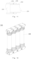
- Fig. 11 shows a manner in which the gas transmission passages 231 of two filtration membrane assemblies are joined end-to-end according to another embodiment of the present invention.
- the outer side wall of the gas transmission passage 231 close to one opening constitutes a first abutting section 232
- the outer side wall of the gas transmission passage 231 close to the other opening constitutes a second abutting section 234.
- the first abutting section 232 can be fixedly, hermetically sleeved on the second abutting section 234 of another filtration membrane assembly.
- first abutting section 232 and the second abutting section 234 are hermetically connected with the aid of a third sealing ring 236.
- the hermetic connection between the first abutting section and the second abutting section can also be achieved in other ways, such as sealant seal or air seal.
- first abutting section 232 and the second abutting section 234 are fixedly connected by interference fit. It can be understood that in another feasible embodiment, the manner in which the first abutting section and the second abutting section are fixedly connected is not limited to that described above. It's also possible that they are connected by clamping.
- the membrane filtration module 300 provided according to an embodiment of the present invention comprises the filtration membrane assembly 100 provided by the present invention.
- the gas transmission passages of adjacent filtration membrane assemblies are joined end-to-end, and thus it's not necessary to provide a gas transmission pipeline for each filtration membrane assembly separately.
- the assembled membrane filtration module has a simple structure and occupies a small space.
- the membrane filtration module 300 further comprises a pressurizing pipeline 310 in communication with the second water stream passage 171b.
- the spacing between the pressurizing pipeline 310 and the second end 115 of the housing 110 is greater than the spacing between the purified water stream passage 171a and the second end 115 of the housing 110.
- the height of the second end cap 170 is higher than the height of the first end cap 130. Therefore, the provision of the pressurizing pipeline 310 can increase the water level in the inner chamber of the housing 110, thereby facilitating the permeation of the purified water through the hollow fiber membrane 150. As such, the filtration efficiency of the membrane filtration module can be improved.
- the height difference between the pressurizing pipeline 310 and the water stream passage 171a is 200 mm to 3000 mm.
- one way to use the membrane filtration module 300 is that the first water stream passage 133 is used as a passage for inputting raw water and discharging concentrated water, and the water stream passage 171a is used as a passage for discharging filtered water.
- the gas transmission passage 131 is used to input compressed air to achieve cleaning of the hollow fiber membrane. After the cleaning is completed, the concentrated water in the inner chamber 111 of the housing 110 may be discharged through the first water stream passage 133.
- the concentrated water can also be discharged through the pressurizing pipeline 310.
- the water stream passage 171b is used as a passage for inputting raw water
- the water stream passage 171a is used as a passage for discharging filtered water. That is, the raw water is input from the end of the water stream passage 171b distal from the pressurizing pipeline 310.
- the gas transmission passage 131 is used to input compressed air to achieve cleaning of the hollow fiber membrane.
- the concentrated water in the inner chamber 111 of the housing 110 may be discharged through the first water stream passage 133.
- the concentrated water can also be discharged through the pressurizing pipeline 310.
Landscapes
- Chemical & Material Sciences (AREA)
- Chemical Kinetics & Catalysis (AREA)
- Life Sciences & Earth Sciences (AREA)
- Hydrology & Water Resources (AREA)
- Engineering & Computer Science (AREA)
- Environmental & Geological Engineering (AREA)
- Water Supply & Treatment (AREA)
- Organic Chemistry (AREA)
- Separation Using Semi-Permeable Membranes (AREA)
Claims (14)
- Hohlfasermembrananordnung (100-1; 200-1; 300-1) vom Typ mit externem Druck, umfassend:- ein Gehäuse (110-1), das eine Innenkammer (111-1) aufweist; und- ein erstes Endelement (130-1; 230-1), das an einem ersten Ende der Innenkammer (111-1) des Gehäuses bereitgestellt ist, wobei das erste Endelement mit einer Vielzahl von leeren Durchgängen (131-1; 231-1; 331-1), die sich entlang einer axialen Richtung des Gehäuses durch das erste Endelement (130-1; 230-1) erstrecken, und einer Vielzahl von Wassersammeldurchgängen (133-1; 233-1; 333-1) bereitgestellt ist, die miteinander in Verbindung stehen, wobei die leeren Durchgänge und die Wassersammeldurchgänge abwechselnd bereitgestellt sind,wobei die Hohlfasermembrananordnung (100-1; 200-1; 300-1) vom Typ mit externem Druck dadurch gekennzeichnet ist, dass sie umfasst:- ein zweites Endelement (130-1), das an einem zweiten Ende der Innenkammer (111-1) des Gehäuses (110-1) bereitgestellt ist, wobei das zweite Endelement mit einer Vielzahl von leeren Durchgängen (131-1), die sich entlang der axialen Richtung des Gehäuses (110-1) durch das zweite Endelement (130-1) erstrecken, und einer Vielzahl von Wassersammeldurchgängen (133-1) bereitgestellt ist, die miteinander in Verbindung stehen, wobei die leeren Durchgänge (131-1) und die Wassersammeldurchgänge (133-1) abwechselnd bereitgestellt sind,- eine erste Endkappe (190-1), die hermetisch mit einem Ende des Gehäuses verbunden ist, wobei ein Impulsbelüfter (180-1) auf einer Seite der ersten Endkappe (190-1) proximal zur Innenkammer (111-1) des Gehäuses (110-1) bereitgestellt ist, wobei der Impulsbelüfter (180-1) proximal zum Endelement (130-1) ein Gasstrom-Freisetzungsloch (181-1) aufweist und das Gasstrom-Freisetzungsloch (181-1) mit dem Impulsbelüfter (180-1) koaxial ist,- eine Vielzahl von Hohlfasermembranbündeln (170-1), die in der Innenkammer (111-1) des Gehäuses (110-1) bereitgestellt sind; wobei die Hohlfasermembranbündel (170-1) eine Breite von kleiner als oder gleich 60 mm aufweisen und ein Verhältnis einer Breite (D1) des Wassersammeldurchgangs (133-1) zu einer Breite (D2) des leeren Durchgangs (131-1) kleiner als 6 ist,wobei eine Vielzahl der leeren Durchlässe (131-1; 231-1; 331-1) verwendet werden, um Schadstoffe an der Außenseite der Hohlfasermembranbündel (170-1) auszutragen, und konfiguriert sind, sodass Rohwasser aus einer Vielzahl der leeren Durchlässe des ersten Endelements in die Innenkammer (111-1) des Gehäuses (110-1) eintritt und aus einer Vielzahl der leeren Durchlässe des zweiten Endelements ausgetragen wird,wobei eine Vielzahl der Wassersammeldurchlässe (133-1; 233-1; 333-1) verwendet werden, um Filtrat aus dem Innenhohlraum einer Hohlfasermembran der Hohlfasermembranbündel (170-1) zu sammeln, und jeder einer Vielzahl der Wassersammeldurchlässe einem separaten Hohlfasermembranbündel entspricht.
- Hohlfasermembrananordnung (100-1) vom Typ mit externem Druck nach Anspruch 1, wobei in einer Richtung senkrecht zur axialen Richtung des Gehäuses (110-1) eine Erstreckungsrichtung des leeren Durchgangs eine Gerade ist, und eine Vielzahl der leeren Durchgänge parallel zueinander sind.
- Hohlfasermembrananordnung (100-1) vom Typ mit externem Druck nach Anspruch 1, wobei das Hohlfasermembranbündel (170-1) in einer Richtung senkrecht zur axialen Richtung des Gehäuses (110-1) einen Querschnitt aufweist, der kreisförmig ist, und einen Außendurchmesser von kleiner als 60 mm aufweist.
- Hohlfasermembrananordnung (200-1) vom Typ mit externem Druck nach Anspruch 1, wobei der leere Durchlass (231-1) in einer Richtung senkrecht zur axialen Richtung des Gehäuses einen Querschnitt aufweist, der fächerförmig oder ringsektorförmig ist.
- Hohlfasermembrananordnung (300-1) vom Typ mit externem Druck nach Anspruch 1, wobei eine Querschnittsfläche des leeren Durchgangs (331-1) senkrecht zur axialen Richtung des Gehäuses (110-1) in der axialen Richtung des Gehäuses von außen nach innen allmählich abnimmt.
- Filtrationsmembrananordnung (100), umfassend:- ein Gehäuse (110), umfassend: eine Innenkammer (111) und ein erstes Ende (113) und ein zweites Ende (115), die einander gegenüberliegen; und- eine erste Endkappe (130), die hermetisch fest mit dem ersten Ende des Gehäuses verbunden ist, wobei die erste Endkappe (130) einen Gasübertragungsdurchgang (131) aufweist, der mit der Innenkammer (111) des Gehäuses (110) in Verbindung steht, und sich auf beiden Seiten öffnet;wobei die Filtrationsmembrananordnung (100) weiter eine Hohlfasermembran (150) und eine zweite Endkappe (170) umfasst, die hermetisch fest mit dem zweiten Ende (115) des Gehäuses (110) verbunden ist;wobei die zweite Endkappe (170) mit einem zweiten Wasserstromdurchgang (171b) und einem Reinwasserstromdurchgang (171a) bereitgestellt ist;wobei der zweite Wasserstromdurchgang (171b) mit einer Außenseite der Hohlfasermembran (150) in Verbindung steht;wobei die Membranfiltrationsanordnung (100) weiter eine Druckbeaufschlagungsleitung (150-1) umfasst, die mit dem zweiten Wasserstromdurchgang (171b) in Verbindung steht; wobei ein Abstand zwischen der Druckbeaufschlagungsleitung (150-1) und dem zweiten Ende des Gehäuses (110-1) größer ist als ein Abstand zwischen dem Reinwasserstromdurchgang (171a) und dem zweiten Ende des Gehäuses,wobei die Hohlfasermembran (150) die Hohlfasermembrananordnung vom Typ mit externem Druck nach einem der Ansprüche 1 bis 5 ist.
- Filtrationsmembrananordnung nach Anspruch 6, wobei die erste Endkappe (130) weiter einen ersten Wasserstromdurchgang (133) aufweist, der mit der Innenkammer (111) des Gehäuses (110) in Verbindung steht, und sich auf beiden Seiten öffnet, wobei der erste Wasserstromdurchgang (133) Ende an Ende mit einem Wasserstromdurchgang einer anderen Filtermembrananordnung zusammengefügt werden kann;
wobei die Filtermembrananordnung (100) weiter eine Verbindungsanordnung (180) umfasst, die lösbar mit beiden, einer Öffnung des Gasübertragungsdurchgangs (131) und einer Öffnung des ersten Wasserstromdurchgangs (133) verbunden ist. - Filtrationsmembrananordnung nach Anspruch 7, wobei die Verbindungsanordnung zwei Doppelloch-Ringhälften (181) umfasst, die lösbar Ende an Ende zusammengefügt werden können, wobei, nachdem die zwei Doppelloch-Ringhälften Ende an Ende zusammengefügt worden sind, zwei Löcher (182) zur Verbindung jeweils mit der Öffnung des Gasübertragungsdurchgangs (131) und der Öffnung des ersten Wasserstromdurchgangs (133) gebildet werden.
- Filtrationsmembrananordnung nach Anspruch 7, wobei eine Außenseitenwand des Gasübertragungsdurchgangs nahe einer der Öffnungen einen ersten Anlageabschnitt bildet und eine Außenseitenwand des Gasübertragungsdurchgangs nahe der anderen der Öffnungen einen zweiten Anlageabschnitt bildet.
- Filtrationsmembrananordnung nach Anspruch 6, die weiter eine zweite Endkappe (170) umfasst, die hermetisch fest mit dem zweiten Ende des Gehäuses verbunden ist, wobei die erste Endkappe (130) mit einer hermetischen Verbindungsanordnung (120) hermetisch mit dem Gehäuse verbunden ist, und/oder die zweite Endkappe (170) mit einer hermetischen Verbindungsanordnung (120) hermetisch mit dem Gehäuse verbunden ist; wobei die erste Endkappe (130) und die zweite Endkappe (170) jeweils einen Verbindungsabschnitt (135) aufweisen, der auf das Gehäuse aufgeschoben werden kann; wobei eine Außenoberfläche des Verbindungsabschnitts (135) mit einem Außengewinde bereitgestellt ist;
wobei die hermetische Verbindungsanordnung (120) umfasst:eine Gewindehülse (121), die auf das Gehäuse (110) aufgeschoben werden kann, wobei eine Innenoberfläche der Gewindehülse umfasst: ein Innengewinde, das mit dem Außengewinde der ersten Endkappe (130) zusammenpasst, und eine Anlageoberfläche (1211); undein Fallschutzstück (127), das auf das Gehäuse (110) aufgeschoben werden kann, wobei eine Oberfläche der Außenseite des Fallschutzstücks zum Anliegen an der Anlageoberfläche (1211) der Gewindehülse (121) verwendet wird. - Filtrationsmembrananordnung nach Anspruch 10, wobei die Anlageoberfläche (1211) der Gewindehülse (121) eine sich verjüngende Oberfläche ist; wobei das Fallschutzstück (127) in Form einer unterbrochenen Schleife vorliegt; wobei eine Innenoberfläche des Fallschutzstücks eine verzahnte Oberfläche ist; und das Fallschutzstück (127) eine Härte aufweist, die größer ist als jene des Gehäuses (110).
- Filtrationsmembrananordnung nach Anspruch 10, wobei die hermetische Verbindungsanordnung (120) weiter einen zweiten Dichtungsring (125) umfasst, der zwischen dem Gehäuse und dem Verbindungsabschnitt (135) der ersten Endkappe (130) oder dem Verbindungsabschnitt der zweiten Endkappe (170) bereitgestellt ist.
- Filtrationsmembrananordnung nach Anspruch 10, wobei die hermetische Verbindungsanordnung (120) weiter einen Stopper (123) umfasst, der auf das Gehäuse (110) aufgeschoben ist; wobei eine Innenoberfläche des Verbindungsabschnitts (135) der ersten Endkappe (130) eine erste Begrenzungsfläche (1351) aufweist; wobei der Stopper (123) eine zweite Begrenzungsfläche (1231) aufweist, die entgegengesetzt zur ersten Begrenzungsfläche (1351) angeordnet ist; wobei die zweite Begrenzungsfläche (1231) nicht parallel zu einer axialen Richtung des Gehäuses (110) verläuft; wobei beide Enden des zweiten Dichtungsrings (125) an der ersten Begrenzungsfläche (1351) und der zweiten Begrenzungsfläche (1231) anliegen; wobei ein Ende des Stoppers (123) distal vom zweiten Dichtungsring (125) am Fallschutzstück (127) anliegt.
- Membranfiltrationsmodul (300), das die Filtrationsmembrananordnung (100) nach einem der Ansprüche 6 bis 13 umfasst.
Applications Claiming Priority (3)
| Application Number | Priority Date | Filing Date | Title |
|---|---|---|---|
| CN201910978302.9A CN110652878A (zh) | 2019-10-15 | 2019-10-15 | 过滤膜组件及膜过滤模块 |
| CN201910979092.5A CN110652879B (zh) | 2019-10-15 | 2019-10-15 | 外压式中空纤维膜组件及过滤装置 |
| PCT/CN2020/115881 WO2021073349A1 (zh) | 2019-10-15 | 2020-09-17 | 外压式中空纤维膜组件、过滤膜组件及膜过滤模块 |
Publications (4)
| Publication Number | Publication Date |
|---|---|
| EP3967389A1 EP3967389A1 (de) | 2022-03-16 |
| EP3967389A4 EP3967389A4 (de) | 2023-01-18 |
| EP3967389C0 EP3967389C0 (de) | 2024-12-18 |
| EP3967389B1 true EP3967389B1 (de) | 2024-12-18 |
Family
ID=75537691
Family Applications (1)
| Application Number | Title | Priority Date | Filing Date |
|---|---|---|---|
| EP20876255.9A Active EP3967389B1 (de) | 2019-10-15 | 2020-09-17 | Hohlfasermembrankomponente mit externem druck, filtrationsmembrankomponente und membranfiltrationsmodul |
Country Status (4)
| Country | Link |
|---|---|
| US (1) | US12097468B2 (de) |
| EP (1) | EP3967389B1 (de) |
| JP (1) | JP7368615B2 (de) |
| WO (1) | WO2021073349A1 (de) |
Families Citing this family (6)
| Publication number | Priority date | Publication date | Assignee | Title |
|---|---|---|---|---|
| US11654401B2 (en) * | 2021-10-25 | 2023-05-23 | Generon Igs, Inc. | Gas separation membrane cartridge with clamshell retainer |
| CN115837220A (zh) * | 2023-02-20 | 2023-03-24 | 天津膜天膜科技股份有限公司 | 无机架式拼装压力式膜组件及膜过滤装备系统 |
| CN118495697B (zh) * | 2024-07-10 | 2025-12-09 | 北京时远科技有限公司 | 一种对流涡流式mbr膜处理装置及其处理工艺 |
| CN119038802B (zh) * | 2024-09-26 | 2025-01-17 | 山东水发优膜科技有限公司 | 一种具有中空纤维陶瓷膜组件的污水处理设备 |
| CN119926177B (zh) * | 2025-02-14 | 2025-10-14 | 烟台金正环保科技有限公司 | 一种平板膜过滤装置 |
| US12502640B1 (en) | 2025-07-15 | 2025-12-23 | Avanpore LLC | Apparatus and method for purification of gas mixtures |
Citations (2)
| Publication number | Priority date | Publication date | Assignee | Title |
|---|---|---|---|---|
| DE102011110591A1 (de) * | 2011-08-18 | 2013-02-21 | Mann + Hummel Gmbh | Filtrationsmodul mit Hohlfasermembranen und Verfahren zum Betreiben eines Filtrationsmoduls für Flüssigkeiten |
| WO2016064466A1 (en) * | 2014-10-22 | 2016-04-28 | Koch Membrane Systems, Inc. | Membrane module system with bundle enclosures and pulsed aeration and method of operation |
Family Cites Families (22)
| Publication number | Priority date | Publication date | Assignee | Title |
|---|---|---|---|---|
| US5536403A (en) * | 1993-07-16 | 1996-07-16 | Sugimoto; Akitoshi | Liquid purification system with microfiltration means, disinfection means and adsorption means |
| DE19811945A1 (de) * | 1998-03-13 | 1999-09-16 | Rochem Ro Wasserbehandlung Gmbh | Vorrichtung zur Trennung von mit Fremdstoffen belasteten flüssigen Medien |
| AUPP985099A0 (en) * | 1999-04-20 | 1999-05-13 | Usf Filtration And Separations Group Inc. | Membrane filtration manifold system |
| AU2002953111A0 (en) * | 2002-12-05 | 2002-12-19 | U. S. Filter Wastewater Group, Inc. | Mixing chamber |
| KR100621484B1 (ko) | 2004-08-27 | 2006-09-14 | 주식회사 퓨어엔비텍 | 중공사막 모듈 |
| JP4951860B2 (ja) * | 2005-01-31 | 2012-06-13 | 東洋紡績株式会社 | 選択透過性膜モジュールの製造方法および選択透過性膜モジュール |
| CN201482424U (zh) | 2009-03-19 | 2010-05-26 | 孟广祯 | 束集成水草式膜过滤器 |
| US9022224B2 (en) * | 2010-09-24 | 2015-05-05 | Evoqua Water Technologies Llc | Fluid control manifold for membrane filtration system |
| KR101798551B1 (ko) * | 2011-03-31 | 2017-11-16 | 코오롱인더스트리 주식회사 | 여과막 모듈 및 이것을 포함하는 여과 시스템 |
| CN202289881U (zh) | 2011-09-30 | 2012-07-04 | 北京坎普尔环保技术有限公司 | 均匀布气的外压膜过滤器 |
| WO2013100272A1 (ko) | 2011-12-28 | 2013-07-04 | 웅진케미칼 주식회사 | 가압식 막모듈 정수장치 |
| DE102013218188B3 (de) | 2013-09-11 | 2014-12-04 | membion Gmbh | Membranfilter und Verfahren zum Filtern |
| DE102013218208B4 (de) * | 2013-09-11 | 2015-06-03 | membion Gmbh | Membranfilter und Verfahren zum Filtern |
| KR101673667B1 (ko) * | 2014-07-31 | 2016-11-07 | 현대자동차주식회사 | 연료전지용 막 가습기의 중공사막 밀집도 분배 장치 |
| KR101674729B1 (ko) * | 2014-09-30 | 2016-11-10 | 주식회사 휴비스워터 | 수처리 모듈 |
| CN105036315B (zh) | 2015-06-16 | 2018-06-26 | 厦门绿邦膜技术有限公司 | 一种曝气中空纤维膜组件及其连接结构 |
| AU2016354941C1 (en) * | 2015-11-19 | 2020-08-27 | Kuraray Co., Ltd. | Hollow fiber membrane module and method of cleaning same |
| CN106669425A (zh) | 2016-03-01 | 2017-05-17 | 海南立昇净水科技实业有限公司 | 一种复合端盖、拼装式过滤膜组、膜过滤单元及系统 |
| US10421032B2 (en) * | 2016-03-11 | 2019-09-24 | Kx Technologies Llc | Modular filtration platform |
| CN206198957U (zh) | 2016-08-17 | 2017-05-31 | 天津沃驰科技有限公司 | 一种新型曝气膜组件 |
| CN110652879B (zh) | 2019-10-15 | 2025-08-12 | 苏州立升净水科技有限公司 | 外压式中空纤维膜组件及过滤装置 |
| CN110652878A (zh) | 2019-10-15 | 2020-01-07 | 苏州立升净水科技有限公司 | 过滤膜组件及膜过滤模块 |
-
2020
- 2020-09-17 EP EP20876255.9A patent/EP3967389B1/de active Active
- 2020-09-17 US US17/596,810 patent/US12097468B2/en active Active
- 2020-09-17 JP JP2022522661A patent/JP7368615B2/ja active Active
- 2020-09-17 WO PCT/CN2020/115881 patent/WO2021073349A1/zh not_active Ceased
Patent Citations (2)
| Publication number | Priority date | Publication date | Assignee | Title |
|---|---|---|---|---|
| DE102011110591A1 (de) * | 2011-08-18 | 2013-02-21 | Mann + Hummel Gmbh | Filtrationsmodul mit Hohlfasermembranen und Verfahren zum Betreiben eines Filtrationsmoduls für Flüssigkeiten |
| WO2016064466A1 (en) * | 2014-10-22 | 2016-04-28 | Koch Membrane Systems, Inc. | Membrane module system with bundle enclosures and pulsed aeration and method of operation |
Also Published As
| Publication number | Publication date |
|---|---|
| EP3967389C0 (de) | 2024-12-18 |
| US12097468B2 (en) | 2024-09-24 |
| WO2021073349A1 (zh) | 2021-04-22 |
| US20220250008A1 (en) | 2022-08-11 |
| EP3967389A4 (de) | 2023-01-18 |
| JP2022552682A (ja) | 2022-12-19 |
| EP3967389A1 (de) | 2022-03-16 |
| JP7368615B2 (ja) | 2023-10-24 |
Similar Documents
| Publication | Publication Date | Title |
|---|---|---|
| EP3967389B1 (de) | Hohlfasermembrankomponente mit externem druck, filtrationsmembrankomponente und membranfiltrationsmodul | |
| CN110652878A (zh) | 过滤膜组件及膜过滤模块 | |
| JP6168056B2 (ja) | 中空糸膜モジュール | |
| US20140054226A1 (en) | Apparatus and method for removing finely divided solids from a liquid flow | |
| CN110652879B (zh) | 外压式中空纤维膜组件及过滤装置 | |
| US9539753B2 (en) | Dirt precipitator for a highly viscous medium | |
| KR200456628Y1 (ko) | 정수필터 구조 | |
| AU728630B2 (en) | Membrane filtration module and membrane filtration system comprising modules of this kind | |
| US7794594B2 (en) | Filter module | |
| US20080000827A1 (en) | Frameless, Plate-Shaped Filtering Member | |
| US20160074795A1 (en) | Filter elements and a filter device having at least one filter element | |
| CN212680646U (zh) | 过滤设备 | |
| CN211328942U (zh) | 过滤膜组件及膜过滤模块 | |
| CN108421414A (zh) | 盘式陶瓷膜超滤装置 | |
| CN211216192U (zh) | 外压式中空纤维膜组件及过滤装置 | |
| CN101778660A (zh) | 过滤系统用反冲装置 | |
| KR200340528Y1 (ko) | 중공사막 여과기의 결합 및 세정장치 | |
| KR102625914B1 (ko) | 수처리장치용 중공사막 모듈 | |
| CN208660835U (zh) | 盘式陶瓷膜超滤装置 | |
| CN114853270B (zh) | 一体化污水处理设备 | |
| JP4078469B2 (ja) | 少くとも1つの透過物の排出口を有する流動媒体の濾過分離装置 | |
| JP7292759B2 (ja) | Mbrシステム | |
| JPS6320003A (ja) | 精密濾過装置 | |
| KR101718161B1 (ko) | 중공사막 고정용 엔드캡 및 이를 포함하는 수처리 모듈 | |
| JP7827225B1 (ja) | 膜ろ過器 |
Legal Events
| Date | Code | Title | Description |
|---|---|---|---|
| STAA | Information on the status of an ep patent application or granted ep patent |
Free format text: STATUS: THE INTERNATIONAL PUBLICATION HAS BEEN MADE |
|
| PUAI | Public reference made under article 153(3) epc to a published international application that has entered the european phase |
Free format text: ORIGINAL CODE: 0009012 |
|
| STAA | Information on the status of an ep patent application or granted ep patent |
Free format text: STATUS: REQUEST FOR EXAMINATION WAS MADE |
|
| 17P | Request for examination filed |
Effective date: 20211210 |
|
| AK | Designated contracting states |
Kind code of ref document: A1 Designated state(s): AL AT BE BG CH CY CZ DE DK EE ES FI FR GB GR HR HU IE IS IT LI LT LU LV MC MK MT NL NO PL PT RO RS SE SI SK SM TR |
|
| A4 | Supplementary search report drawn up and despatched |
Effective date: 20221216 |
|
| DAV | Request for validation of the european patent (deleted) | ||
| DAX | Request for extension of the european patent (deleted) | ||
| RIC1 | Information provided on ipc code assigned before grant |
Ipc: C02F 1/44 20060101ALI20221213BHEP Ipc: B01D 65/02 20060101ALI20221213BHEP Ipc: B01D 63/02 20060101AFI20221213BHEP |
|
| STAA | Information on the status of an ep patent application or granted ep patent |
Free format text: STATUS: EXAMINATION IS IN PROGRESS |
|
| 17Q | First examination report despatched |
Effective date: 20240215 |
|
| GRAP | Despatch of communication of intention to grant a patent |
Free format text: ORIGINAL CODE: EPIDOSNIGR1 |
|
| STAA | Information on the status of an ep patent application or granted ep patent |
Free format text: STATUS: GRANT OF PATENT IS INTENDED |
|
| GRAS | Grant fee paid |
Free format text: ORIGINAL CODE: EPIDOSNIGR3 |
|
| INTG | Intention to grant announced |
Effective date: 20241009 |
|
| GRAA | (expected) grant |
Free format text: ORIGINAL CODE: 0009210 |
|
| STAA | Information on the status of an ep patent application or granted ep patent |
Free format text: STATUS: THE PATENT HAS BEEN GRANTED |
|
| AK | Designated contracting states |
Kind code of ref document: B1 Designated state(s): AL AT BE BG CH CY CZ DE DK EE ES FI FR GB GR HR HU IE IS IT LI LT LU LV MC MK MT NL NO PL PT RO RS SE SI SK SM TR |
|
| REG | Reference to a national code |
Ref country code: CH Ref legal event code: EP |
|
| REG | Reference to a national code |
Ref country code: DE Ref legal event code: R096 Ref document number: 602020043509 Country of ref document: DE |
|
| REG | Reference to a national code |
Ref country code: IE Ref legal event code: FG4D |
|
| U01 | Request for unitary effect filed |
Effective date: 20250106 |
|
| U07 | Unitary effect registered |
Designated state(s): AT BE BG DE DK EE FI FR IT LT LU LV MT NL PT RO SE SI Effective date: 20250115 |
|
| PG25 | Lapsed in a contracting state [announced via postgrant information from national office to epo] |
Ref country code: HR Free format text: LAPSE BECAUSE OF FAILURE TO SUBMIT A TRANSLATION OF THE DESCRIPTION OR TO PAY THE FEE WITHIN THE PRESCRIBED TIME-LIMIT Effective date: 20241218 |
|
| PG25 | Lapsed in a contracting state [announced via postgrant information from national office to epo] |
Ref country code: NO Free format text: LAPSE BECAUSE OF FAILURE TO SUBMIT A TRANSLATION OF THE DESCRIPTION OR TO PAY THE FEE WITHIN THE PRESCRIBED TIME-LIMIT Effective date: 20250318 |
|
| PG25 | Lapsed in a contracting state [announced via postgrant information from national office to epo] |
Ref country code: GR Free format text: LAPSE BECAUSE OF FAILURE TO SUBMIT A TRANSLATION OF THE DESCRIPTION OR TO PAY THE FEE WITHIN THE PRESCRIBED TIME-LIMIT Effective date: 20250319 |
|
| PG25 | Lapsed in a contracting state [announced via postgrant information from national office to epo] |
Ref country code: RS Free format text: LAPSE BECAUSE OF FAILURE TO SUBMIT A TRANSLATION OF THE DESCRIPTION OR TO PAY THE FEE WITHIN THE PRESCRIBED TIME-LIMIT Effective date: 20250318 |
|
| PG25 | Lapsed in a contracting state [announced via postgrant information from national office to epo] |
Ref country code: SM Free format text: LAPSE BECAUSE OF FAILURE TO SUBMIT A TRANSLATION OF THE DESCRIPTION OR TO PAY THE FEE WITHIN THE PRESCRIBED TIME-LIMIT Effective date: 20241218 |
|
| PG25 | Lapsed in a contracting state [announced via postgrant information from national office to epo] |
Ref country code: PL Free format text: LAPSE BECAUSE OF FAILURE TO SUBMIT A TRANSLATION OF THE DESCRIPTION OR TO PAY THE FEE WITHIN THE PRESCRIBED TIME-LIMIT Effective date: 20241218 |
|
| PG25 | Lapsed in a contracting state [announced via postgrant information from national office to epo] |
Ref country code: ES Free format text: LAPSE BECAUSE OF FAILURE TO SUBMIT A TRANSLATION OF THE DESCRIPTION OR TO PAY THE FEE WITHIN THE PRESCRIBED TIME-LIMIT Effective date: 20241218 |
|
| PG25 | Lapsed in a contracting state [announced via postgrant information from national office to epo] |
Ref country code: IS Free format text: LAPSE BECAUSE OF FAILURE TO SUBMIT A TRANSLATION OF THE DESCRIPTION OR TO PAY THE FEE WITHIN THE PRESCRIBED TIME-LIMIT Effective date: 20250418 |
|
| PG25 | Lapsed in a contracting state [announced via postgrant information from national office to epo] |
Ref country code: SK Free format text: LAPSE BECAUSE OF FAILURE TO SUBMIT A TRANSLATION OF THE DESCRIPTION OR TO PAY THE FEE WITHIN THE PRESCRIBED TIME-LIMIT Effective date: 20241218 |
|
| PG25 | Lapsed in a contracting state [announced via postgrant information from national office to epo] |
Ref country code: CZ Free format text: LAPSE BECAUSE OF FAILURE TO SUBMIT A TRANSLATION OF THE DESCRIPTION OR TO PAY THE FEE WITHIN THE PRESCRIBED TIME-LIMIT Effective date: 20241218 |
|
| U20 | Renewal fee for the european patent with unitary effect paid |
Year of fee payment: 6 Effective date: 20250813 |
|
| PGFP | Annual fee paid to national office [announced via postgrant information from national office to epo] |
Ref country code: GB Payment date: 20250919 Year of fee payment: 6 |
|
| PLBE | No opposition filed within time limit |
Free format text: ORIGINAL CODE: 0009261 |
|
| STAA | Information on the status of an ep patent application or granted ep patent |
Free format text: STATUS: NO OPPOSITION FILED WITHIN TIME LIMIT |
|
| 26N | No opposition filed |
Effective date: 20250919 |