EP3967410A1 - Récipient pour liquide de pulvérisation - Google Patents
Récipient pour liquide de pulvérisation Download PDFInfo
- Publication number
- EP3967410A1 EP3967410A1 EP21183701.8A EP21183701A EP3967410A1 EP 3967410 A1 EP3967410 A1 EP 3967410A1 EP 21183701 A EP21183701 A EP 21183701A EP 3967410 A1 EP3967410 A1 EP 3967410A1
- Authority
- EP
- European Patent Office
- Prior art keywords
- pump
- container
- protrusion
- tube
- spraying liquid
- Prior art date
- Legal status (The legal status is an assumption and is not a legal conclusion. Google has not performed a legal analysis and makes no representation as to the accuracy of the status listed.)
- Withdrawn
Links
- 239000007788 liquid Substances 0.000 title claims abstract description 22
- 238000005507 spraying Methods 0.000 title claims abstract description 21
- 238000003780 insertion Methods 0.000 claims abstract description 44
- 230000037431 insertion Effects 0.000 claims abstract description 44
- 238000000926 separation method Methods 0.000 claims description 7
- 230000000903 blocking effect Effects 0.000 claims 1
- 239000002537 cosmetic Substances 0.000 description 4
- 238000007599 discharging Methods 0.000 description 4
- 239000002304 perfume Substances 0.000 description 3
- 230000000694 effects Effects 0.000 description 2
- 239000007921 spray Substances 0.000 description 2
- 239000000126 substance Substances 0.000 description 2
- 239000002386 air freshener Substances 0.000 description 1
- 230000004075 alteration Effects 0.000 description 1
- 230000003247 decreasing effect Effects 0.000 description 1
- 239000000645 desinfectant Substances 0.000 description 1
- 239000003599 detergent Substances 0.000 description 1
- 239000002917 insecticide Substances 0.000 description 1
- 239000000463 material Substances 0.000 description 1
- 238000012986 modification Methods 0.000 description 1
- 230000004048 modification Effects 0.000 description 1
- 230000000149 penetrating effect Effects 0.000 description 1
- 230000000630 rising effect Effects 0.000 description 1
- 239000002453 shampoo Substances 0.000 description 1
- 239000012780 transparent material Substances 0.000 description 1
Images





Classifications
-
- B—PERFORMING OPERATIONS; TRANSPORTING
- B05—SPRAYING OR ATOMISING IN GENERAL; APPLYING FLUENT MATERIALS TO SURFACES, IN GENERAL
- B05B—SPRAYING APPARATUS; ATOMISING APPARATUS; NOZZLES
- B05B11/00—Single-unit hand-held apparatus in which flow of contents is produced by the muscular force of the operator at the moment of use
- B05B11/0005—Components or details
- B05B11/0037—Containers
- B05B11/0038—Inner container disposed in an outer shell or outer casing
-
- B—PERFORMING OPERATIONS; TRANSPORTING
- B05—SPRAYING OR ATOMISING IN GENERAL; APPLYING FLUENT MATERIALS TO SURFACES, IN GENERAL
- B05B—SPRAYING APPARATUS; ATOMISING APPARATUS; NOZZLES
- B05B11/00—Single-unit hand-held apparatus in which flow of contents is produced by the muscular force of the operator at the moment of use
- B05B11/01—Single-unit hand-held apparatus in which flow of contents is produced by the muscular force of the operator at the moment of use characterised by the means producing the flow
- B05B11/10—Pump arrangements for transferring the contents from the container to a pump chamber by a sucking effect and forcing the contents out through the dispensing nozzle
-
- B—PERFORMING OPERATIONS; TRANSPORTING
- B05—SPRAYING OR ATOMISING IN GENERAL; APPLYING FLUENT MATERIALS TO SURFACES, IN GENERAL
- B05B—SPRAYING APPARATUS; ATOMISING APPARATUS; NOZZLES
- B05B11/00—Single-unit hand-held apparatus in which flow of contents is produced by the muscular force of the operator at the moment of use
- B05B11/0005—Components or details
- B05B11/0037—Containers
- B05B11/0039—Containers associated with means for compensating the pressure difference between the ambient pressure and the pressure inside the container, e.g. pressure relief means
- B05B11/0044—Containers associated with means for compensating the pressure difference between the ambient pressure and the pressure inside the container, e.g. pressure relief means compensating underpressure by ingress of atmospheric air into the container, i.e. with venting means
-
- B—PERFORMING OPERATIONS; TRANSPORTING
- B05—SPRAYING OR ATOMISING IN GENERAL; APPLYING FLUENT MATERIALS TO SURFACES, IN GENERAL
- B05B—SPRAYING APPARATUS; ATOMISING APPARATUS; NOZZLES
- B05B11/00—Single-unit hand-held apparatus in which flow of contents is produced by the muscular force of the operator at the moment of use
- B05B11/01—Single-unit hand-held apparatus in which flow of contents is produced by the muscular force of the operator at the moment of use characterised by the means producing the flow
- B05B11/10—Pump arrangements for transferring the contents from the container to a pump chamber by a sucking effect and forcing the contents out through the dispensing nozzle
- B05B11/1042—Components or details
-
- B—PERFORMING OPERATIONS; TRANSPORTING
- B05—SPRAYING OR ATOMISING IN GENERAL; APPLYING FLUENT MATERIALS TO SURFACES, IN GENERAL
- B05B—SPRAYING APPARATUS; ATOMISING APPARATUS; NOZZLES
- B05B11/00—Single-unit hand-held apparatus in which flow of contents is produced by the muscular force of the operator at the moment of use
- B05B11/01—Single-unit hand-held apparatus in which flow of contents is produced by the muscular force of the operator at the moment of use characterised by the means producing the flow
- B05B11/10—Pump arrangements for transferring the contents from the container to a pump chamber by a sucking effect and forcing the contents out through the dispensing nozzle
- B05B11/1042—Components or details
- B05B11/1043—Sealing or attachment arrangements between pump and container
- B05B11/1046—Sealing or attachment arrangements between pump and container the pump chamber being arranged substantially coaxially to the neck of the container
- B05B11/1047—Sealing or attachment arrangements between pump and container the pump chamber being arranged substantially coaxially to the neck of the container the pump being preassembled as an independent unit before being mounted on the container
-
- B—PERFORMING OPERATIONS; TRANSPORTING
- B05—SPRAYING OR ATOMISING IN GENERAL; APPLYING FLUENT MATERIALS TO SURFACES, IN GENERAL
- B05B—SPRAYING APPARATUS; ATOMISING APPARATUS; NOZZLES
- B05B11/00—Single-unit hand-held apparatus in which flow of contents is produced by the muscular force of the operator at the moment of use
- B05B11/01—Single-unit hand-held apparatus in which flow of contents is produced by the muscular force of the operator at the moment of use characterised by the means producing the flow
- B05B11/10—Pump arrangements for transferring the contents from the container to a pump chamber by a sucking effect and forcing the contents out through the dispensing nozzle
- B05B11/1042—Components or details
- B05B11/1052—Actuation means
-
- B—PERFORMING OPERATIONS; TRANSPORTING
- B05—SPRAYING OR ATOMISING IN GENERAL; APPLYING FLUENT MATERIALS TO SURFACES, IN GENERAL
- B05B—SPRAYING APPARATUS; ATOMISING APPARATUS; NOZZLES
- B05B11/00—Single-unit hand-held apparatus in which flow of contents is produced by the muscular force of the operator at the moment of use
- B05B11/01—Single-unit hand-held apparatus in which flow of contents is produced by the muscular force of the operator at the moment of use characterised by the means producing the flow
- B05B11/10—Pump arrangements for transferring the contents from the container to a pump chamber by a sucking effect and forcing the contents out through the dispensing nozzle
- B05B11/1042—Components or details
- B05B11/1066—Pump inlet valves
-
- B—PERFORMING OPERATIONS; TRANSPORTING
- B05—SPRAYING OR ATOMISING IN GENERAL; APPLYING FLUENT MATERIALS TO SURFACES, IN GENERAL
- B05B—SPRAYING APPARATUS; ATOMISING APPARATUS; NOZZLES
- B05B15/00—Details of spraying plant or spraying apparatus not otherwise provided for; Accessories
- B05B15/30—Dip tubes
-
- B—PERFORMING OPERATIONS; TRANSPORTING
- B05—SPRAYING OR ATOMISING IN GENERAL; APPLYING FLUENT MATERIALS TO SURFACES, IN GENERAL
- B05B—SPRAYING APPARATUS; ATOMISING APPARATUS; NOZZLES
- B05B11/00—Single-unit hand-held apparatus in which flow of contents is produced by the muscular force of the operator at the moment of use
- B05B11/0005—Components or details
- B05B11/0027—Means for neutralising the actuation of the sprayer ; Means for preventing access to the sprayer actuation means
- B05B11/0032—Manually actuated means located downstream the discharge nozzle for closing or covering it, e.g. shutters
-
- B—PERFORMING OPERATIONS; TRANSPORTING
- B05—SPRAYING OR ATOMISING IN GENERAL; APPLYING FLUENT MATERIALS TO SURFACES, IN GENERAL
- B05B—SPRAYING APPARATUS; ATOMISING APPARATUS; NOZZLES
- B05B11/00—Single-unit hand-held apparatus in which flow of contents is produced by the muscular force of the operator at the moment of use
- B05B11/01—Single-unit hand-held apparatus in which flow of contents is produced by the muscular force of the operator at the moment of use characterised by the means producing the flow
- B05B11/10—Pump arrangements for transferring the contents from the container to a pump chamber by a sucking effect and forcing the contents out through the dispensing nozzle
- B05B11/1001—Piston pumps
- B05B11/1023—Piston pumps having an outlet valve opened by deformation or displacement of the piston relative to its actuating stem
Definitions
- the present invention relates to a container for spraying liquid that has an improvement in the passage structure for discharging the content.
- a pump is coupled to the opening at the upper part of a container holding a liquid content such as a perfume, etc., to dispense and spray the content to the exterior in designated amounts.
- a liquid content such as a perfume, etc.
- the user presses down on a nozzle corresponding to a button so as to spray the liquid content the content that had entered the inside of the pump is pressurized, moved upward along the discharge passage, and sprayed through the nozzle.
- the pressure on the nozzle is released, the discharge passage is mechanically closed by the rising of the nozzle, the pressure inside the pump is decreased, and the content is drawn in from the container to compensate.
- a pump such as the above is being used not only for spraying perfumes and cosmetics but also a variety of other contents such as air fresheners, insecticides, etc. Due to the convenience of dispensing designated amounts of a content with a single pressing of the nozzle without having the content exposed to the exterior, the demand for the pump continues to grow.
- a conventional pump and a typical structure for a container having a coupled pump are disclosed in documents such as Korean Registered Patent No. 1963619 .
- the pump In order to dispense the content from the body in which the content is stored, the pump is connected to a long hose, with the lower end of the hose reaching the bottom of the body. The suctioning force of the pump is transferred to the hose, whereby the content stored in the body is drawn in through the hose to the pump.
- the hose may also lower the aesthetic of the body, as the hose is inserted into the body and visible from the exterior. The problem of lowered aesthetic is particularly conspicuous when the body corresponds to a cosmetic container. As such, containers that use pumps are often fabricated with the body made from an opaque material, in order that the hose may not be seen from the exterior.
- An aspect of the present invention which was derived to resolve the problem described above, is to provide a container for spraying liquid in which the hose can be omitted due to an improvement in the passage structure for discharging the content.
- a container for spraying liquid that includes: a tube in which a filling space is formed; a body in which the tube is inserted, where the outer perimeter of the tube and the inner perimeter of the body form a body outlet passage, a lower tube hole is formed in a lower part of the tube as an entrance to the body outlet passage, and an upper movement hole is formed in an upper part of the body as an exit from the body outlet passage; a body cover coupled to the upper part of the body, where the body cover includes a cover channel and a pump insertion space, the cover channel connects with the upper movement hole, and the pump insertion space connects with the cover channel and has a pump inserted therein; and a pump support coupled to an upper part of the body cover and supporting the pump in a manner that blocks the entry of outside air into the pump insertion space.
- a container according to an embodiment of the present invention can include one or more of the following features.
- the container can additionally include a shoulder coupled to an upper part of the pump support and pressing down on the pump.
- a separation protrusion can be formed on a bottom surface of the pump insertion space such that a gap is formed between the pump and the bottom surface.
- a center hole in which the pump insertion space may be inserted can be formed in the upper part of the body, an outlet protrusion can be formed on one side of the center hole, and the upper movement hole can be formed on the inside of the outlet protrusion.
- the body cover can include a passage protrusion, which may be inserted in the inside of the outlet protrusion and may connect with cover channel.
- the pump support can include a contact protrusion that tightly contacts the periphery of the pump.
- the body can have a horizontal cross section shaped as any one of a triangle, a quadrilateral, a circle, and an ellipse.
- the shoulder can include a detent protrusion that presses down on the pump, a shoulder air hole can be formed in the detent protrusion, a support air groove that connects with the shoulder air hole can be formed in the pump support, an air nozzle that connects with the support air groove can be formed on the body, and the air nozzle can connect with the filling space.
- the body cover can include an air inlet protrusion in which the air nozzle may be inserted.
- a base can be coupled to a lower part of the body. Also, a pump for dispensing the content can be additionally included.
- An embodiment of the present invention having the features above can provide various advantageous effects including the following.
- an embodiment of the present invention may not necessarily exhibit all of the effects below.
- An embodiment of the present invention can provide a container in which the hose for discharging the content can be omitted.
- a container for spraying liquid according to this embodiment can be used for spraying various types of liquid such as cosmetics, perfumes, shampoos, detergents, disinfectants, chemicals, etc., and is not limited by the type or property of the content being sprayed.
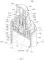
- FIG. 1 is a perspective view of a container 100 for spraying liquid according to a first disclosed embodiment of the present invention.
- FIG. 2 is a cross-sectional perspective view of the container 100 illustrated in FIG. 1
- FIG. 3 is a cross-sectional perspective view showing an upper part of the container 100 illustrated in FIG. 2 .
- the arrows in FIG. 3 illustrate the flow of the content as it is discharged.
- a container 100 based on this embodiment has the hose omitted from the filling space 112 of the tube 140 storing the content (not shown) and has the passage for discharging the content formed as a circular body outlet passage 113 by having the tube 140 inserted within a body 110.
- the container 100 based on this embodiment can be made to have a simple structure as well as an improved aesthetic, since there is no hose visible even when the body 110 and the tube 140 are made from transparent materials.
- a container 100 based on this embodiment includes a body 110, a tube 140, a body cover 160, a pump support 180, a shoulder 210, a nozzle 230, a pump 240, and an upper cap 260.
- the upper cap 260 has the shape of a hollow column and is open at the bottom.
- the upper cap 260 is coupled to a periphery of the shoulder 210 to cover the nozzle 230.
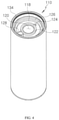
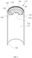
- FIG. 4 and FIG. 5 are perspective views of the body 110 of the container 100 illustrated in FIG. 1 .
- a filling space 112 for storing the content is formed within the body 110, where the filling space 112 is divided from the body outlet passage 113 by the tube 140.
- the tube 140 has the shape of a hollow cylinder in the same manner as the body 110 and is inserted within the body 110 such that the outer perimeter of the tube 140 and the inner perimeter of the body 110 form the body outlet passage 113.
- the body outlet passage 113 has the horizontal cross section forming an annular shape and has the overall appearance of the perimeter part of a cylinder.
- the body outlet passage 113 can be formed with a small gap.
- the body outlet passage 113 can lead to a pump insertion space 164 of the body cover 160 via an upper movement hole 130.
- the body outlet passage 113 corresponds to the passage through which the content moves upward. That is, due to the operation of the pump 240, the content is drawn into and moved upward along the body outlet passage 113 and passes through the upper movement hole 130 and cover channel 168 and into the pump insertion space 164. In this way, the body outlet passage 113 is formed along the entire inner perimeter of the body 110 to provide a passage through which the content can move.
- the present invention is not limited by the cross-sectional shape of the body 110.
- another embodiment of the present invention can have the body formed with any of a variety of cross-sectional shapes including polygonal shapes, such as triangles and quadrilaterals, and elliptical shapes, among others.
- the tube inserted inside the body can have a cross-sectional shape corresponding to that of the body.
- a body coupler part 118 having a concave shape.
- the body cover 160, the pump support 180, and the shoulder 210 are coupled onto the body coupler part 118.
- a body center hole 120 is formed in the center of the body coupler part 118, and a center protrusion 122 is formed around the body center hole 120.
- the body center hole 120 connects with the filling space 112, and the pump insertion space 164 of the body cover 160 is inserted therein.
- the center protrusion 122 has a cross section shaped as an inverted "L" and has the pump insertion space 164 inserted therethrough. Also, the inner end portion of the center protrusion 122 can press against the outer perimeter of the pump insertion space 164, thereby preventing any entry of outside air or foreign substances through the body center hole 120.
- an air hole 124 is formed that connects with the filling space 112.
- An air nozzle 146 of the tube 140 is inserted through the air hole 124, allowing outside air to enter the interior of the filling space 112 through the air nozzle 146.
- an outlet protrusion 128 having the shape of a hollow cylinder, where an upper movement hole 130 that can connect with the filling space 112 is formed in a portion of the bottom surface of the outlet protrusion 128.
- the content that has entered through the body outlet passage 113 moves through the upper movement hole 130 and outlet protrusion 128 and then moves through the cover channel 168 of the body cover 160 into the pump insertion space 164.
- a passage protrusion 172 formed on a lower surface of the body cover 160 is inserted within the outlet protrusion 128.
- an upper step 126 is formed around the body center hole 120. Also, around the upper step 126, there is formed a body coupler groove 136. A coupler periphery member 214 of the shoulder 210 is inserted in the body coupler groove 136.
- a body detent groove 134 On the inner perimeter of the upper part forming the body coupler part 118, there can be formed a body detent groove 134.
- a coupler protrusion 216 formed on the outer perimeter of the shoulder 210 can be inserted into the body detent groove 134, so that the shoulder 210 can be firmly coupled to the body 110.
- a lower step 132 is formed at the other end of the body 110.
- a base 138 is coupled to the lower step 132 to seal off the lower end of the body 110.
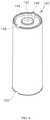
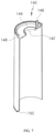
- FIG. 6 and FIG. 7 are perspective views of the tube 140 of the container 100 illustrated in FIG. 1 .
- the tube 140 has the shape of a hollow cylinder corresponding to that of the body 110 and has the filling space 112 formed therein for storing the content.
- the tube 140 is inserted within the body 110 such that the annularly shaped body outlet passage 113, which corresponds to a passage for the movement of the content, is formed between the outer perimeter of the tube 140 and the inner perimeter of the body 110.
- the tube 140 is structured to have an open bottom and a partially sealed top in a manner similar to that of the body 110.
- a tube center hole 142 is formed in the center of an upper part of the tube 140.
- the tube center hole 142 connects with the body center hole 120 of the body 110, and the pump insertion space 164 is inserted therein.
- a center protrusion 144 protruding upward. The center protrusion 144 is inserted within the center protrusion 122 of the body 110.
- an air nozzle 146 protrudes from one side of the tube center hole 142.
- the air nozzle 146 has the shape of a hollow cylinder and has its other end connecting with the inside of the tube 140 (i.e., the filling space 112).
- the air nozzle 146 is inserted into an air inlet protrusion 177 formed on the body cover 160. The outside air that has entered through the air nozzle 146 is drawn into the filling space 112 to prevent a pressure decrease.
- an upper tube hole 148 is formed in an upper part of the tube 140.
- the upper tube hole 148 corresponds to an exit for the body outlet passage 113, and the content moves through the upper tube hole 148 and then through the passage protrusion 172 and cover channel 168.
- a lower tube hole 150 is formed in a lower part of the tube 140.
- the lower tube hole 150 corresponds to an entrance for the body outlet passage 113, and the content moves through the lower tube hole 150 into the body outlet passage 113.
- the upper tube hole 148 and the lower tube hole 150 can be positioned along a straight line on the outer perimeter of the tube 140. Also, at least one of the upper tube hole 148 and the lower tube hole 150 can be provided in multiple numbers.
- FIG. 8 and FIG. 9 are a perspective view and a perspective cross-sectional view illustrating the body cover 160.
- the body cover 160 is coupled to an upper part of the body 110 and has the pump support 180 and the shoulder 210 coupled sequentially to an upper part thereof.
- the body cover 160 includes a cover plane 162 and an upper periphery member 174, which protrudes upward from a face of the cover plane 162 and has an annular shape with an open top.
- the pump insertion space 164, the cover channel 168, securing protrusions 173, and the air inlet protrusion 177 are provided on the inside of the upper periphery member 174.
- the passage protrusion 172 protrudes downward from the lower surface of the cover plane 162.
- the pump insertion space 164 is a cavity formed concavely in the center of the cover plane 162 and has a circular horizontal cross section.
- a housing 246 of the pump 240 is inserted within the pump insertion space 164.
- a lower inlet hole 247 is formed in a lower surface of the housing 246, and the content that has been drawn into the pump insertion space 164 is drawn through the lower inlet hole 247 into the inside of the housing 246.
- the pump insertion space 164 protrudes downward from the cover plane 162, and this part is inserted into the body center hole 120 of the body 110 and the tube center hole 142 of the tube 140.
- One side of the upper part of the pump insertion space 164 connects with the cover channel 168.
- the content that has entered through the cover channel 168 moves downward to the bottom of the pump insertion space 164 and is drawn into the housing 246.
- a multiple number of separation protrusions 166 can be disposed in a circular arrangement.
- the separation protrusions 166 can have a particular length, and multiple separation protrusions 166 can be disposed with a particular gap in-between.
- the housing 246 of the pump 240 touches the separation protrusions 166 and is separated from the bottom surface of the pump insertion space 164 by a corresponding height. Thus, the content that has entered the pump insertion space 164 can be drawn into the housing 246 through the gaps formed in-between the separation protrusions 166.
- the cover channel 168 having a particular width and depth, is formed in a straight line in the cover plane 162.
- the cover channel 168 can have a cross section of a quadrilateral shape and can have one end connected with a cover inlet hole 170 and the other end connected with the pump insertion space 164.
- the cover channel 168 is defined by a bottom surface and two side surfaces, and its open top is closed off by the pump support 180.
- the cover inlet hole 170 formed at one end of the cover channel 168 is formed penetrating through the cover plane 162 and connects with the internal space of the passage protrusion 172.
- the passage protrusion 172 protrudes from the lower surface of the cover plane 162 and is structured in the shape of a hollow cylinder with its lower end open.
- the passage protrusion 172 has its upper end closed off by the pump support 180 so as to connect to the cover channel 168 through the cover inlet hole 170 only.
- the passage protrusion 172 is inserted into the outlet protrusion 128 formed on the upper part of the body 110.
- securing protrusions 173 formed, which, together with the air inlet protrusion 177, can be disposed in an arrangement shaped as a regular triangle.
- the securing protrusions 173 are inserted respectively into two second insertion cavities 198 formed in the lower part of the pump support 180, whereby the pump support 180 is coupled to the upper part of the body cover 160.
- An inner periphery member 184 and an outer periphery member 182 of the pump support 180 are positioned at the inner perimeter and outer perimeter, respectively, of the upper periphery member 174.
- the upper periphery member 174 is inserted into a coupler groove 186 formed between the inner periphery member 184 and outer periphery member 182.
- an air inlet protrusion 177 having the shape of a hollow cylinder.
- the upper end and lower end of the air inlet protrusion 177 are both open, and the air nozzle 146 of the tube 140 is inserted therein. Air can be drawn into the filling space 112 of the body 110 through the open upper end of the air nozzle 146.
- FIG. 10 and FIG. 11 are a perspective view and a perspective cross-sectional view illustrating the pump support 180.
- the pump support 180 is coupled to an upper part of the body cover 160 to support the pump 240 in a stable manner while preventing the entry of outside air into the pump insertion space 164.
- the pump support 180 includes at its center the support body 190, which has the shape of a hollow cylinder, and includes the outer periphery member 182 and inner periphery member 184 formed around the support body 190.
- the outer periphery member 182 and inner periphery member 184 have annularly shaped cross sections, and the coupler groove 186 corresponding to a gap is formed therebetween.
- the upper periphery member 174 of the body cover 160 is inserted into the coupler groove 186 by way of press fitting.
- a placement step 188 is formed on an upper part of the outer periphery member 182, where an upper surface of the placement step 188 is pressed downward by a pressing protrusion 218 provided on the inside of the shoulder 210.
- the support body 190 is positioned on the inside of the inner periphery member 184 and has a height greater than that of the inner periphery member 184.
- a body detent groove 192 is formed in the outer perimeter of the support body 190, and inner coupler protrusions 222 formed on the inside of the shoulder 210 are inserted into the body detent groove 192.
- Such a body detent groove 192 and inner coupler protrusions 222 allow the shoulder 210 to be coupled to the pump support 180 in a stable manner.
- the housing 246 of the pump 240 is inserted into the empty space within the support body 190.
- a contact protrusion 204 having an annular shape is formed on the inner perimeter of a lower part of the support body 190. The contact protrusion 204 presses against and tightly contacts the outer perimeter of the housing 246 of the pump 240, whereby outside air is prevented from entering the inside of the pump insertion space 164.
- a support air groove 202 which extends from the upper end by a particular length.
- a particular gap is formed between the support air groove 202 and the housing 246 of the pump 240, and air enters through this gap to the upper end of the air nozzle 146 of the tube 140.
- An empty space is formed between the inner periphery member 184 and the support body 190, and in this empty space, there are formed a first insertion cavity 196 and two second insertion cavities 198 that include their respective upper surfaces 197, 199.
- the first insertion cavity 196 and second insertion cavities 198 correspond to empty spaces that are closed off at the top by the upper surfaces 197, 199 and open at the bottom.
- An air inlet protrusion 177 formed on the body cover 160 is inserted into the first insertion cavity 196. Since the upper end of the air inlet protrusion 177 does not touch the upper surface 197, a passage is formed therebetween through which air can move. Also, the securing protrusions 173 are inserted into the second insertion cavities 198, allowing the pump support 180 to be coupled to the upper part of the body cover 160 in a stable manner.
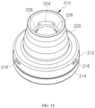
- FIG. 12 and FIG. 13 are a perspective view and a perspective cross-sectional view illustrating the shoulder 210.
- the shoulder 210 couples to the upper part of the pump support 180 to press down on the pump 240 and has the nozzle 230 coupled to an upper part thereof.
- the shoulder 210 includes a hollow pump coupler part 220 and a shoulder coupler part 212 that is formed around the pump coupler part 220 and is open at the bottom only.
- the shoulder coupler part 212 includes a coupler periphery member 214, which is inserted into the body coupler part 118 as already described above. Since the bottom of the shoulder coupler part 212 is open, the body cover 160 and the pump support 180 are housed therein.
- the shoulder coupler part 212 includes an upper surface (no number assigned), and the pump coupler part 220 is formed in a protruding manner in the center of the upper surface. Also, a coupler protrusion 216 can be formed on the periphery of the shoulder coupler part 212. The coupler protrusion 216 is inserted into the body detent groove 134 formed in the inner perimeter of the body coupler part 118.
- the pressing protrusion 218 On the inside of the pump coupler part 220, the pressing protrusion 218 having the shape of a hollow cylinder is formed.
- the pressing protrusion 218 presses down on the placement step 188 of the pump support 180, whereby the pump support 180 and the pump 240 are coupled to the body 110 in a stable manner.
- the pump coupler part 220 is structured in the shape of a hollow conical frustum with both the upper end and lower end open.
- the pump 240 and the support body 190 are inserted within the pump coupler part 220.
- the lower end of the pump coupler part 220 connects with the interior space of the shoulder coupler part 212.
- an annularly shaped detent protrusion 224 is formed protruding inwardly.
- the detent protrusion 224 is partially cut away to form shoulder air holes 226.
- the detent protrusion 224 presses down on a flange 245 formed around the housing 246 of the pump 240, whereby the pump 240 is secured to the pump insertion space 164 in a stable manner.
- the flange 245 does not touch the upper end of the support body 190 of the pump support 180 and is separated by a particular gap. Due to this gap, air from outside the container 100 can move through the shoulder air holes 226, the air inlet protrusion 177, and the air nozzle 146 to enter the inside of the filling space 112.
- the shoulder air holes 226 correspond to arc shaped holes formed as portions of the detent protrusion 224 are cut away.
- the inner coupler protrusions 222 are formed protruding from below the shoulder air holes 226.
- a multiple number of inner coupler protrusions 222 are formed in particular intervals on the inner perimeter of the pump coupler part 220.
- the inner coupler protrusions 222 are inserted in the body detent groove 192 formed in the outer perimeter of the support body 190.
- FIG. 14 is a perspective cross-sectional view illustrating the nozzle 230
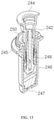
- FIG. 15 is a perspective cross-sectional view illustrating the pump 240.
- the nozzle 230 includes a nozzle protrusion 232 that couples with a valve 244 of the pump 240, and the nozzle protrusion 232 connects with a discharge exit 234.
- the valve 244 includes a nozzle periphery member 236, which is partially inserted within the pump coupler part 220 of the shoulder 210.
- the valve 244 is elastically supported by a spring (not shown), so that when an external force applied on the nozzle 230 is removed, the valve 244 is raised by the elastic restoring force of the spring.
- the nozzle 230 is covered by the upper cap 260.
- the pump 240 has its lower part inserted in the pump insertion space 164 formed in the body cover 160 and is secured in position as the housing 246 is pressed downward by the detent protrusion 224 of the shoulder 210.
- the pump 240 draws the content into the inside of the pump insertion space 164 and applies suction that allows the content to be discharged through the nozzle 230.
- the pump 240 includes a housing 246, a valve 244, a housing cover 250, a piston 248, and a guide 242, which form a structure that is identical or similar to the pump structure disclosed in Korean Registered Patent No. 1963619 and thus are not described here in further detail.
- the suctioning force of the pump 240 causes the content in the filling space 112 to enter the body outlet passage 113 through the lower tube hole 150 formed in the lower part of the tube 140, move up, and pass through the upper movement hole 130 to be discharged out of the body outlet passage 113.
- the content enters the passage protrusion 172 and then passes through the cover inlet hole 170 and cover channel 168 to enter the inside of the pump insertion space 164.
- the content is moved from the pump insertion space 164 to the inside of the housing 246 by the suctioning force of the pump 240 and discharged through the nozzle 230 to the exterior of the container 100.
- the container 100 since the container 100 according to this embodiment does not include a hose for suctioning the content inside the body 110, the embodiment can provide a simplified structure and can resolve the problem of the hose hurting the aesthetic of the container.
- outside air is drawn into the pump coupler part 220 through the gap (no number assigned) formed between the nozzle 230 and the inner perimeter of the pump coupler part 220.
- the air that has entered the pump coupler part 220 moves through the shoulder air holes 226, the support air groove 202, and the air nozzle 146 to enter the inside of the filling space 112.
- the suctioning force of the pump 240 can be maintained at a particular level.
Landscapes
- Containers And Packaging Bodies Having A Special Means To Remove Contents (AREA)
- Closures For Containers (AREA)
Applications Claiming Priority (1)
| Application Number | Priority Date | Filing Date | Title |
|---|---|---|---|
| KR1020200116080A KR102356611B1 (ko) | 2020-09-10 | 2020-09-10 | 액체 분사를 위한 용기 |
Publications (1)
| Publication Number | Publication Date |
|---|---|
| EP3967410A1 true EP3967410A1 (fr) | 2022-03-16 |
Family
ID=76765036
Family Applications (1)
| Application Number | Title | Priority Date | Filing Date |
|---|---|---|---|
| EP21183701.8A Withdrawn EP3967410A1 (fr) | 2020-09-10 | 2021-07-05 | Récipient pour liquide de pulvérisation |
Country Status (6)
| Country | Link |
|---|---|
| US (1) | US12097515B2 (fr) |
| EP (1) | EP3967410A1 (fr) |
| JP (1) | JP7294705B2 (fr) |
| KR (1) | KR102356611B1 (fr) |
| CN (1) | CN114162452B (fr) |
| WO (1) | WO2022055044A1 (fr) |
Families Citing this family (4)
| Publication number | Priority date | Publication date | Assignee | Title |
|---|---|---|---|---|
| KR102383616B1 (ko) * | 2020-09-10 | 2022-04-14 | 주식회사 삼화 | 액체 분사를 위한 용기 |
| KR102403988B1 (ko) * | 2020-10-05 | 2022-06-02 | 주식회사 삼화 | 액체 분사를 위한 용기 |
| KR102478899B1 (ko) * | 2021-10-08 | 2022-12-20 | 주식회사 삼화 | 튜브리스 토출 용기 |
| KR102374962B1 (ko) * | 2021-12-10 | 2022-03-16 | 주식회사 동호인더스 | 미스트 분사기용 용기하우징 |
Citations (2)
| Publication number | Priority date | Publication date | Assignee | Title |
|---|---|---|---|---|
| FR2828480A1 (fr) * | 2001-08-10 | 2003-02-14 | Oreal | Dispositif de distribution d'un produit sans tube plongeur |
| KR101963619B1 (ko) | 2018-09-20 | 2019-03-29 | (주)삼화피앤티 | 스프레이 펌프 |
Family Cites Families (41)
| Publication number | Priority date | Publication date | Assignee | Title |
|---|---|---|---|---|
| US4793527A (en) * | 1987-09-18 | 1988-12-27 | Alfonso Di Stefano | Aerosol dispenser |
| US5738250A (en) * | 1997-04-07 | 1998-04-14 | Calmar Inc. | Liquid dispensing pump having water seal |
| CN2314128Y (zh) * | 1997-12-25 | 1999-04-14 | 丁要武 | 乳液泵防进水机构 |
| GB2344857B (en) * | 1998-12-15 | 2001-03-14 | Bespak Plc | Improvements in or relating to dispensing apparatus |
| US6176395B1 (en) * | 1999-04-21 | 2001-01-23 | Pechiney Plastic Packaging, Inc. | Dual dispense container |
| US6695171B2 (en) * | 2002-02-12 | 2004-02-24 | Seaquistperfect Dispensing Foreign, Inc. | Pump dispenser |
| DE10220557A1 (de) * | 2002-05-02 | 2003-11-13 | Pfeiffer Erich Gmbh & Co Kg | Spender zum Austrag fließfähiger Medien |
| JP2004106940A (ja) | 2002-08-29 | 2004-04-08 | Yoshino Kogyosho Co Ltd | 二重容器 |
| DE10354053A1 (de) * | 2003-11-17 | 2005-06-16 | Beiersdorf Ag | Kosmetische oder dermatologische Zubereitungen zur Applikation mit Spendersystemen |
| NL1026093C2 (nl) * | 2004-04-29 | 2005-11-01 | Airspray Nv | Afgifte-inrichting. |
| KR101226461B1 (ko) * | 2005-07-29 | 2013-01-28 | 가부시키가이샤 요시노 고교쇼 | 토출용기 |
| JP4943731B2 (ja) * | 2005-09-30 | 2012-05-30 | 株式会社吉野工業所 | ポンプ付き二剤混合容器 |
| KR200416530Y1 (ko) * | 2006-02-18 | 2006-05-16 | 강성일 | 에어리스 배출펌프를 가진 화장품용기 |
| US20090008413A1 (en) * | 2007-04-17 | 2009-01-08 | Choi Hee Jin | Airless dispensing pump container with an airtight push down type nozzle head |
| JP2010222014A (ja) | 2009-03-20 | 2010-10-07 | Kalu Co Ltd | ディスペンサ用ノズル |
| KR101067748B1 (ko) * | 2009-10-09 | 2011-09-28 | (주)연우 | 거품분출 튜브용기 |
| GB201000601D0 (en) * | 2010-01-14 | 2010-03-03 | Rieke Corp | Pump dispensers |
| JP5487011B2 (ja) | 2010-05-31 | 2014-05-07 | 株式会社ダイゾー | 多層ボトル製品の製造方法および該製造方法により製造された多層ボトル製品 |
| EP2629896B1 (fr) * | 2010-10-20 | 2024-04-10 | Silgan Dispensing Systems Corporation | Mécanismes de pompe et leurs procédés de fabrication |
| CN201878765U (zh) * | 2010-11-01 | 2011-06-29 | 常州市富艾发进出口有限公司 | 口吸式便携雾化器 |
| US20130043283A1 (en) * | 2011-08-18 | 2013-02-21 | Jisong Lin | Efoam pump with spring isolated from flow path |
| KR200464671Y1 (ko) * | 2011-08-29 | 2013-01-15 | 주식회사 아폴로산업 | 액체용기용 펌프디스펜서 |
| US9248462B2 (en) * | 2011-12-01 | 2016-02-02 | Yonwoo Co., Ltd. | Airless pump system |
| GB2506182B (en) * | 2012-09-25 | 2018-05-30 | Derjin Hong Kong Holding Company Ltd | Lotion spray head assembly |
| KR101352541B1 (ko) * | 2013-09-02 | 2014-01-16 | 변영광 | 펌핑시 소리가 나는 토출 펌프 |
| FR3016618B1 (fr) * | 2014-01-17 | 2016-02-19 | Aptar France Sas | Reservoir de produit fluide et distributeur integrant un tel reservoir. |
| KR101554210B1 (ko) * | 2014-03-04 | 2015-09-21 | (주)연우 | 진공펌프가 구비된 크림타입 화장품용기 |
| JP5961240B2 (ja) * | 2014-11-10 | 2016-08-02 | 昭三 後藤 | ポンプ付き容器 |
| CN204713677U (zh) * | 2015-03-16 | 2015-10-21 | 周宇平 | 吸管泵压式液体瓶 |
| WO2016205408A1 (fr) * | 2015-06-15 | 2016-12-22 | The Plant Based Company | Pulvérisateur d'oméga-3 |
| US10166563B2 (en) * | 2016-01-08 | 2019-01-01 | Silgan Dispensing Systems Corporation | Pump systems, pump engines, and methods of making the same |
| KR20200029872A (ko) * | 2018-09-11 | 2020-03-19 | (주)연우 | 이중 용기 |
| KR101951627B1 (ko) * | 2018-09-20 | 2019-02-25 | (주)삼화피앤티 | 스프레이 펌프 |
| KR101975847B1 (ko) * | 2018-09-20 | 2019-05-07 | (주)삼화피앤티 | 스프레이 펌프 |
| US12098713B2 (en) * | 2019-08-12 | 2024-09-24 | Zhejiang Z&Z Industrial Co., Ltd. | Vacuum pump |
| CN210815844U (zh) * | 2019-10-17 | 2020-06-23 | 李鸣 | 无出液管式喷壶 |
| KR102102223B1 (ko) * | 2019-12-20 | 2020-05-29 | (주)민진 | 에코 펌프 방식의 에어리스 화장품 용기 |
| KR102383616B1 (ko) * | 2020-09-10 | 2022-04-14 | 주식회사 삼화 | 액체 분사를 위한 용기 |
| KR102403988B1 (ko) * | 2020-10-05 | 2022-06-02 | 주식회사 삼화 | 액체 분사를 위한 용기 |
| US20230092170A1 (en) * | 2021-09-23 | 2023-03-23 | Apackaging Group Llc | All Plastic High Pressure Pump |
| KR102573274B1 (ko) * | 2021-10-08 | 2023-08-31 | 주식회사 삼화 | 튜브리스 토출 용기 |
-
2020
- 2020-09-10 KR KR1020200116080A patent/KR102356611B1/ko active Active
- 2020-12-18 JP JP2021568062A patent/JP7294705B2/ja active Active
- 2020-12-18 WO PCT/KR2020/018622 patent/WO2022055044A1/fr not_active Ceased
-
2021
- 2021-07-05 EP EP21183701.8A patent/EP3967410A1/fr not_active Withdrawn
- 2021-07-07 US US17/369,898 patent/US12097515B2/en active Active
- 2021-07-09 CN CN202110778510.1A patent/CN114162452B/zh active Active
Patent Citations (2)
| Publication number | Priority date | Publication date | Assignee | Title |
|---|---|---|---|---|
| FR2828480A1 (fr) * | 2001-08-10 | 2003-02-14 | Oreal | Dispositif de distribution d'un produit sans tube plongeur |
| KR101963619B1 (ko) | 2018-09-20 | 2019-03-29 | (주)삼화피앤티 | 스프레이 펌프 |
Also Published As
| Publication number | Publication date |
|---|---|
| CN114162452A (zh) | 2022-03-11 |
| WO2022055044A1 (fr) | 2022-03-17 |
| CN114162452B (zh) | 2024-08-13 |
| US12097515B2 (en) | 2024-09-24 |
| JP7294705B2 (ja) | 2023-06-20 |
| US20220072573A1 (en) | 2022-03-10 |
| KR102356611B1 (ko) | 2022-02-08 |
| JP2022551362A (ja) | 2022-12-09 |
Similar Documents
| Publication | Publication Date | Title |
|---|---|---|
| US12097515B2 (en) | Container for spraying liquid | |
| US5024355A (en) | Device for dispensing a liquid or a cream in small-volume drops, and an associated dispensing assembly | |
| US5277340A (en) | Dispensing container | |
| US5617976A (en) | Dispenser of liquid or pasty product which can be used especially in cosmetics | |
| US20150260179A1 (en) | Fluent Product Dispensing Package and Diaphragm Pump For Use Therein | |
| KR101817077B1 (ko) | 수동식 이중 분사장치 | |
| KR101403741B1 (ko) | 화장품 용기 | |
| US12409467B2 (en) | Container for spraying liquid | |
| EP3766587A1 (fr) | Orifice et récipient de pulvérisation le comprenant | |
| JPH02229564A (ja) | 逆止弁 | |
| US11857986B2 (en) | Tubeless dispenser container | |
| KR102383616B1 (ko) | 액체 분사를 위한 용기 | |
| KR102176512B1 (ko) | 이종 내용물 혼합 용기 | |
| KR20220112079A (ko) | 화장품용 미스트 디스펜서 | |
| KR102643135B1 (ko) | 액체 분사를 위한 용기 | |
| KR102579766B1 (ko) | 액체 분사를 위한 용기 | |
| KR20210064892A (ko) | 이종 내용물 토출 용기 | |
| KR102573275B1 (ko) | 액체 분사를 위한 용기 | |
| KR20240000843U (ko) | 풀림방지 스토퍼 구조를 갖는 스프레이 액상용기 | |
| KR102427032B1 (ko) | 펌프 | |
| KR20210064894A (ko) | 이종 내용물 토출 용기 | |
| KR102478899B1 (ko) | 튜브리스 토출 용기 | |
| KR20250144048A (ko) | 부유 캡슐을 함유하는 내용물을 토출하기 위한 토출펌프, 이에 사용되는 튜브형 스프링 및 이들을 구비한 토출용기 | |
| KR20170004202U (ko) | 수동식 이중 분사장치 |
Legal Events
| Date | Code | Title | Description |
|---|---|---|---|
| PUAI | Public reference made under article 153(3) epc to a published international application that has entered the european phase |
Free format text: ORIGINAL CODE: 0009012 |
|
| STAA | Information on the status of an ep patent application or granted ep patent |
Free format text: STATUS: REQUEST FOR EXAMINATION WAS MADE |
|
| 17P | Request for examination filed |
Effective date: 20210705 |
|
| AK | Designated contracting states |
Kind code of ref document: A1 Designated state(s): AL AT BE BG CH CY CZ DE DK EE ES FI FR GB GR HR HU IE IS IT LI LT LU LV MC MK MT NL NO PL PT RO RS SE SI SK SM TR |
|
| STAA | Information on the status of an ep patent application or granted ep patent |
Free format text: STATUS: THE APPLICATION IS DEEMED TO BE WITHDRAWN |
|
| 18D | Application deemed to be withdrawn |
Effective date: 20220917 |