EP3967555B1 - Lastenträger - Google Patents
Lastenträger Download PDFInfo
- Publication number
- EP3967555B1 EP3967555B1 EP20195926.9A EP20195926A EP3967555B1 EP 3967555 B1 EP3967555 B1 EP 3967555B1 EP 20195926 A EP20195926 A EP 20195926A EP 3967555 B1 EP3967555 B1 EP 3967555B1
- Authority
- EP
- European Patent Office
- Prior art keywords
- engaging
- supporting
- operating member
- arrangement
- movable
- Prior art date
- Legal status (The legal status is an assumption and is not a legal conclusion. Google has not performed a legal analysis and makes no representation as to the accuracy of the status listed.)
- Active
Links
Images



Classifications
-
- B—PERFORMING OPERATIONS; TRANSPORTING
- B60—VEHICLES IN GENERAL
- B60R—VEHICLES, VEHICLE FITTINGS, OR VEHICLE PARTS, NOT OTHERWISE PROVIDED FOR
- B60R9/00—Supplementary fittings on vehicle exterior for carrying loads, e.g. luggage, sports gear or the like
- B60R9/06—Supplementary fittings on vehicle exterior for carrying loads, e.g. luggage, sports gear or the like at vehicle front or rear
-
- B—PERFORMING OPERATIONS; TRANSPORTING
- B60—VEHICLES IN GENERAL
- B60R—VEHICLES, VEHICLE FITTINGS, OR VEHICLE PARTS, NOT OTHERWISE PROVIDED FOR
- B60R9/00—Supplementary fittings on vehicle exterior for carrying loads, e.g. luggage, sports gear or the like
- B60R9/04—Carriers associated with vehicle roof
- B60R9/042—Carriers characterised by means to facilitate loading or unloading of the load, e.g. rollers, tracks, or the like
Definitions
- the invention relates to a load carrier, in particular a bike carrier, which is mountable on the rear of a vehicle.
- Load carriers for attachment to the rear of vehicles are known in the prior art, for example from US 2003/099531 A1 .
- Such load carriers are very popular especially for recreational vehicles and vans, as access to the roof and roof-mounted support systems is more difficult with these types of vehicles.
- it is advantageous, especially with heavier objects to be transported, if these need not be lifted for attachment to the load carrier, since this is cumbersome and unergonomic for the user.
- rear-mounted load carriers comprise the advantage that they are easily accessible from the rear of the vehicle.
- the load carrier can be a bike carrier.
- Vehicles can be e.g. a recreational vehicle or a van, wherein it is also possible to attach the load carrier to a caravan or other suitable trailers.
- the load carrier comprises a supporting arrangement for supporting a load to be transported.
- the supporting arrangement may comprise a loading platform.
- the load carrier may comprise a movement mechanism or shifting mechanism.
- the movement mechanism is embodied as a lifting mechanism which is adapted to move the supporting arrangement between a raised position and a lowered position.
- the load carrier further comprises a locking mechanism which is adapted to releasably lock the supporting arrangement in the raised position.
- the locking mechanism is configured to automatically establish locking when the supporting arrangement reaches the raised position.
- the movement mechanism or shifting mechanism may be configured such that it does not or not substantially change the height of the supporting arrangement upon operation of the same when the load carrier is mounted.
- the load carrier may be a load carrier which is mounted on a trailer, for example a caravan.
- a load carrier may for example be mounted on the trailer chassis or caravan chassis, for example at a forward end portion of the trailer.
- the latter arrangement can be an A-frame mountable load carrier.
- load carriers may comprise a shifting mechanism for translating the load carrier horizontally forwards and backwards in order to grant access to a compartment on the trailer, for example a front compartment of a caravan.
- Such an A-frame mountable load carrier may comprise a movement mechanism as exemplary described herein with respect to the lifting mechanism with the difference that the movement direction is differently oriented, namely horizontally.
- the locking mechanism may also be used in connection with such load carrier arrangements and may comprise the same features with different orientation.
- the locking mechanism may be configured to releasably lock the bike carrier in a travel position and to allow an extension to an access position when the locking mechanism is unlocked.
- the movement mechanism is not used for allowing an easier loading but for granting access.
- Such a mechanism may also be used in rear mounted bike carriers that are mounted on a towing hitch in order to grant access to a trunk of a vehicle.
- the lifting mechanism comprises a stationary portion fixedly mountable to the vehicle and a movable portion movable relative to the stationary portion.
- the supporting arrangement is coupled to the movable portion.
- the locking mechanism may comprise an engaging assembly which is configured to releasably establish a positive locking between the movable portion and the stationary portion of the lifting mechanism, for at least limiting a movement of the movable portion relative to the stationary portion.
- the term "at least limiting movement” is to be understood as including a configuration in which the positive locking leads to an immediate blocking such that a movement of the movable part is fully suspended or prevented, but also as including a configuration in which a movement remains possible to a certain extent, as is for example achieved when an engaging member engages with an opening which has a larger inner size compared to the outer size of the engaging member.
- the engaging assembly can be provided on the movable portion so as to be integrally movable with the supporting arrangement.
- the engaging assembly can be provided on the stationary portion.
- the engaging assembly can be provided on a lower end portion of the movable portion. Such a configuration provides a good accessibility for a user.
- the engaging assembly may be arranged at a different position.
- the engaging assembly can comprise an engaging portion and the stationary portion can comprise a receiving portion or vice versa.
- the engaging portion can comprise a pin or a hook like member.
- the engaging portion is movable between an engaging position in which the engaging portion is engaged with the receiving portion and a release position in which the engaging portion is not engaged with the receiving portion.
- the receiving portion can be provided in a lower end portion of the stationary portion.
- the engaging assembly comprises an urging member which prebiases the engaging portion towards the engaging position.
- the urging member can comprise a spring, for example a coil spring.
- the engaging assembly may comprise an operating member operatively coupled to the engaging portion for moving the engaging portion.
- the operating member may be operatively coupled to the engaging portion by means of a force transfer member.
- the force transfer member may be any mechanism that allows the transfer of a force, for example comprising a wire, belt, chain and/or gears.
- the operating member may comprise or may be operatively coupled to an operating portion configured to be grasped by a user for manually moving the operating member to an unlocking position in which the engaging portion is positioned in the release position.
- the stationary portion may comprise a trigger portion adapted to cooperate with the engaging assembly.
- the operating member may comprise an actuation portion configured to contact the trigger portion or may be operatively coupled to an actuation portion.
- the trigger portion and the actuation portion may be configured such that the engaging assembly is triggered when the actuation portion, for example an operating member comprising the actuation portion, passes the trigger portion.
- the actuation portion may contact the trigger portion upon passing the trigger portion.
- the actuation portion may slidably contact the trigger portion upon passing the trigger portion.
- the engaging assembly may comprise a supporting portion.
- the supporting portion may be a housing.
- the housing may be cuboid.
- the supporting portion may be configured for movably supporting, for example translatory movably supporting, the engaging portion and/or the force transfer member.
- the supporting portion can be configured to pivotably support the operating member thereon.
- the operating member and the engaging portion can be coupled to each other such that a pivoting movement of the operating member is transferred into a translatory movement of the engaging portion.
- the supporting portion may comprise a supporting surface for slidably supporting the operating member thereon.
- the operating member may comprise a coupling portion for pivotably coupling the engaging portion to the operating member.
- the operating member can further comprise a cam portion with a cam surface contacting and riding on the supporting surface. The operating member can be prebiased towards the supporting surface.
- the cam surface can be formed such that the operating member comprises a self-locking capability.
- the cam surface can comprise a first surface section contacting the supporting surface when the operating member is in the unlocking position in which the engaging portion is in the release position.
- the cam surface can comprise a second surface section contacting the supporting surface when the operating member is in the unlocking position in which the engaging portion is in unlocking position.
- the cam surface can comprise a third surface section connecting the first surface section and the second surface section.
- the third surface section can be formed as an apex portion.
- the load carrier may comprise a drive assembly for driving the movable portion.
- the drive assembly may be an electric drive assembly.
- the electric drive assembly may comprise an electric motor for driving the movable portion.
- the drive assembly can be coupled to a control unit.
- the control unit can comprise a receiver for wirelessly receiving operating information from a remote controller.
- the load carrier may comprise a safety arrangement.
- the safety arrangement can be configured such that power is supplied to the drive assembly only when the operating member is in the unlocking position.
- the safety arrangement can comprise a switch.
- the switch can be a cut-off switch.
- the cut-off switch can be contact operated and can comprise a contact portion which is to be contacted to operate the switch.
- the operating member can be configured and arranged such that contact with the switch is released when the operating member is positioned in the unlocking position thereby establishing a power supply.
- the safety arrangement can alternatively or additionally be configured to cut off the power supply to the drive assembly when it is detected that an object is clamped between the stationary portion and the movable portion.
- the safety arrangement can comprise a sensor arrangement, for example a contact sensor arrangement.
- the sensor arrangement can be provided on a lower end portion of the stationary portion.
- the sensor arrangement can comprise a movable member protruding from the lower end portion of the stationary portion.
- the movable member can be a cover, for example an outer cover.
- the cover can be configured to at least partially cover the lower end portion, for example a portion of a longitudinal end surface, for example facing the movable portion.
- the sensor arrangement can further comprise a switch, for example a cut-off switch, for cutting off the power supply to the drive assembly.
- the switch can be operable by the movable member such that it is activated when the movable member has moved by a predetermined distance.
- a safety arrangement can be provided which is configured to indicate a correctly established locking of the supporting arrangement in the raised position, i.e. in the transport position.
- the safety arrangement can be configured to indicate an active power supply.
- the safety arrangement can comprise an indicator.
- the indicator can be an optical indicator such as a signal light.
- the indicator can also be an acoustic indicator.
- the indicator can be coupled to the cut-off switch.
- the lifting mechanism can be configured as a telescoping arrangement in which the stationary portion comprises a first elongate profile and the movable portion comprises a second elongate profile.
- a third elongate profile may be provided.
- the elongate profiles may be coupled to each other such that adjacent profiles are movable with respect to each other, for example such that adjacent elongate profiles can roll on each other or can slide on each other.
- Adjacent profiles such as the second profile in the third profile and/or the first profile and the third profile can be movably coupled to each other by means of two coupling portions in such a manner that in a retracted state of the lifting mechanism, coupling positions of the adjacent profiles are arranged at a greater distance from each other than in an extended state of the lifting mechanism.
- the load carrier can comprise two stationary portions and two movable portions.
- the locking mechanism for example the engaging assembly, can be configured to simultaneously establish the releasable positive locking between the movable portions and the stationary portions by means of a single engaging assembly.
- the engaging assembly may then comprise an engaging portion for each combination of a movable portion and a stationary portion wherein all engaging portions are operatively coupled to one or more operating members which are configured to simultaneously operate all engaging portions.
- the locking mechanism can be configured to automatically establish locking when the supporting arrangement reaches the transport position, for example a raised position.
- the supporting arrangement can be pivotably coupled to the lifting mechanism so as to be transferable between a stowing state and a use state by pivoting the supporting arrangement towards and away from the lifting mechanism.
- the supporting arrangement may comprise a locking arrangement for arresting the supporting arrangement in the use state.
- the locking arrangement may comprise an engaging member.
- the engaging member can be engageable with a lower end portion of the movable portion.
- the engaging member can be engageable with a lower portion of the engaging assembly, for example with an opening provided in the lower portion.
- the locking arrangement can further comprise an operating device which may be a rotatable handle.
- the operating device can be operatively coupled to the engaging member by a force transfer mechanism.
- the force transfer mechanism can be fully accommodated in the supporting arrangement, for example in a frame structure of the supporting arrangement.
- the engaging member can be prebiased towards engagement by means of an urging member.
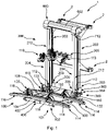
- FIG. 1 shows a perspective view of a load carrier 1 according to an embodiment.
- the load carrier 1 comprises a supporting arrangement 100 and a movement mechanism 200 which in the present embodiment is configured as a shifting mechanism. Since shifting takes place in the height direction in the load carrier 1 according to the embodiment, such a shifting mechanism will be referred to as lifting mechanism in the following.
- the movement mechanism may be configured such that the movement takes place in another direction, for example in a horizontal direction.
- Such an arrangement may be used on A-frame load carriers for caravans, for instance, in which the load carrier is mounted on a front end of the caravan. In such arrangements, the movement mechanism can be constructed similar but is installed and used in a different orientation.
- a load carrier may be provided with a supporting arrangement which is horizontally movable.
- the supporting arrangement 100 is configured to support a load to be transported.
- supporting arrangement 100 may be configured such that a load to be transported is supported from below.
- the supporting arrangement 100 comprises a loading platform 101.
- the loading platform 101 may comprise a frame structure 102.
- the frame structure 102 comprises a cross member 104 and two elongate members 106, 108.
- the cross member 104 and the elongate members 106, 108 comprise profiles which may be manufactured by aluminum extrusion. However other manufacturing methods are also conceivable.
- the profiles may be closed profiles or may be profiles which are partially open.
- the cross member 104 and the elongate members 106, 108 may be coupled to each other to form a C-shape.
- the cross member 104 and the elongate members 106, 108 may be formed substantially straight and the cross member 104 may be coupled to end portions of the elongate members 106, 108 to form the C-shape. Furthermore, the elongate members 106, 108 may be arranged so as to extend substantially perpendicular to the cross member 104. It is noted that other shapes of the frame structure 102 are also conceivable in which the cross bar 104 and/or the elongate members 106, 108 comprise other shapes including curved portions and kinked portions. In the configuration as shown in Figure 1 , the frame structure 102 is formed to define a supporting plane on which further elements of the loading platform 101 may be fixed.
- the loading platform 101 may be configured for supporting bikes.
- the loading platform 101 can comprise a bike supporting arrangement 114 fixedly mounted to the frame structure 102.
- a bike supporting arrangement 114 fixedly mounted to the frame structure 102.
- two bike supporting arrangements 114 are provided but the overall number of bike supporting arrangements 114 may be different and may include more than two bike supporting arrangements.
- Each bike supporting arrangement 114 may be coupled the elongate members 106, 108 of the frame structure 102.
- Each bike supporting arrangement 114 may comprise a wheel tray 116 and a wheel fixation arrangement 118, preferably two wheel fixation arrangements 118.
- Each wheel fixation arrangement 118 may be slidably and releasably detachably held on the wheel tray 116 so as to be positionable at different longitudinal positions of the wheel tray 116 depending on the dimensions of a bike to be supported.
- Each wheel fixation arrangement 118 may comprise a strap 124 forming a fixation loop for a bike wheel.
- the supporting arrangement 100 is coupled to the lifting mechanism 200.
- the supporting arrangement 100 is pivotably coupled to the lifting mechanism 200.
- the supporting arrangement 100 comprises coupling members 110 which are fixedly coupled to free end portions of the elongate members 106, 108, that is to the end portions of the elongate members 106, 108 which are not coupled to each other by the cross member 104.
- Each coupling member 110 comprises a coupling portion 112.
- Each coupling portion 112 can be pivotably mounted on the lifting mechanism 200, more precisely on a movable portion 204 of the lifting mechanism 200, for example on a second elongate profile 212 of the movable portion 204.
- Each coupling portion 112 may be pivotably coupled to a lower end portion 206 of the movable portion 204. Accordingly, by moving the movable portion 204, the supporting arrangement 100 is moved as well.
- the lifting mechanism 200 will be described in greater detail below.
- the supporting arrangement 100 may further comprise an engaging portion 122 in the free end portions of the frame structure 102.
- the engaging portion 122 is configured to be engaged with a lower end portion of the movable portion 204 of the lifting mechanism 200 in order to temporarily prevent a pivoting movement of the supporting arrangement 100 into the stowing position. Accordingly, the engaging portion 122 may be configured to detachably lock the supporting arrangement 100 to the lifting mechanism 200.
- the engaging portion 122 may form part of a locking arrangement 400 as will be described below.
- the locking arrangement 400 may comprise an operating device 402 for operating the locking arrangement 400.
- the operating device 402 may be arranged on the cross member 104.
- the operating device 402 at a different position including a position on the elongate members 106, 108, for instance.
- other elements of the locking arrangement 400 may be concealed in the supporting arrangement 100, for example in the frame structure 102.
- the lifting mechanism 200 of the load carrier 1 is mountable to the rear of a vehicle by means of an upper coupling portion 2 and a lower coupling portion 3.
- the load carrier 1 comprises two upper coupling portions 2 and two lower coupling portions 3.
- the lifting mechanism 200 comprises a stationary portion 202.
- the stationary portion 202 remains fixed during operation of the lifting mechanism 200 and is coupled to the vehicle by means of the upper and lower coupling portions 2, 3.
- the lifting mechanism 200 comprises a movable portion 204 the movable portion 204 is movable relative to the stationary portion 202. Since the supporting arrangement 100 is coupled to the movable portion 204 as already mentioned before, the position of the supporting arrangement 100 may be changed by moving the movable portion 204 relative to the stationary portion 202.
- the stationary portion 202 and the movable portion 204 are formed as elongate units. In a mounted condition of the load carrier 1, the stationary portion 202 and the movable portion 204 may extend in vertical direction. The stationary portion 202 and the movable portion 204 may be arranged so as to be movable in parallel with respect to each other.
- the stationary portion 202 comprises a first end portion 201 which may form an upper end portion in case the stationary portion 202 extends vertically when the load carrier 1 is mounted on a vehicle.
- the first end portion 201 is an upper end portion.
- the first end portion 201 may also be a rear portion in case the movement mechanism 200 is oriented horizontally as is conceivable in connection with the above mentioned A-frame mountable load carriers.
- the stationary portion 202 further comprises a second end portion 203.
- the second end portion 203 is a lower end portion.
- the second end portion 203 may also be a front end portion in case the movement mechanism 200 is oriented horizontally as is conceivable in connection with the above mentioned A-frame load carriers.
- a receiving portion 500 which will be described later in greater detail is provided at the second end portion 203.
- the receiving portion 500 is configured to cooperate with a locking mechanism 300 provided on the movable portion 204 of the movement mechanism 200.
- the locking mechanism 300 will later be described in greater detail although it is already indicated in the embodiment as shown in Figure 1 that such locking mechanism 300 may comprise an engaging assembly 350 and an operating member 302 for operating the locking mechanism 300. It is further noted that an inverse arrangement is also possible. Accordingly, in a modification the receiving portion 500 may be provided on the movable portion 204 and the locking mechanism 300 may be provided on the stationary portion 202.
- the load carrier 1 further comprises a drive assembly 600.
- the drive assembly 600 is an electric drive assembly.
- a drive assembly which is manually driven, for example by means of a crank.
- a drive assembly 600 which is operable both electrically and manually in order to provide for an arrangement that allows an operation in case one of the available operation possibilities comprises a malfunction.
- the drive assembly 600 is provided on the first end portion 201, more precisely on an upper end portion 201.
- the drive assembly 600 comprises a casing 602 accommodating and an electric motor (not shown) as well as components of the force transfer mechanism (not shown) for driving the movable portion 204.
- the movable portion 204 may comprise a support member 205.
- the support member 205 may be arranged to extend between two parallel second elongate profiles 212.
- the support member 205 is configured to support a further bike fixation member which is embodied as a frame gripping unit 119.
- an attachment member 113 is arranged on the support member 205 and configured to hold the supporting arrangement 100 in a stowed position.
- the attachment member 113 is pivotably mounted on the support member 205 at one end and releasably engageable with the cross member 104 at its other end.
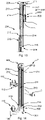
- FIG. 2 shows the load carrier 1 in an extended condition.
- the lifting mechanism 200 is configured as a three-way telescoping mechanism.
- the stationary portion 202 comprises the first elongate profile 211.
- the movable portion 204 comprises a second elongate profile 212 and a third elongate profile 213.
- the third elongate profile 213 is arranged between the first elongate profile 211 and the second elongate profile 212.
- the lifting mechanism 200 comprises a first elongate profile in the stationary portion 202 and a single further elongate profile, for example the second elongate profile 212, in the movable portion 204. Furthermore, it is possible to provide configurations with more than three elongate profiles. Accordingly, while the stationary portion 202 may always comprise a single elongate profile the movable portion 204 may comprise one or more elongate profiles. As can already be gathered from Figures 1 and 2 , the elongate profiles may comprise a similar length or the same length.
- the drive assembly 600 is operatively coupled at least with the second elongate profile 212 so as to drive the second elongate profile 212.
- the driving device of the drive assembly 600 for example an electric motor, can be operatively coupled to the second elongate profile 212 by means of a force transfer mechanism including one of a wire, a belt, a chain or a gear mechanism.
- an indicator 712 may be arranged in the drive assembly 600, more precisely in the casing 602 of the drive assembly 600. The function of the indicator 712 will be described later in connection with a safety arrangement 700 which may optionally be provided in the load carrier 1.
- the locking mechanism 300 is configured to lock the second elongate profile 212 with at least the first elongate profile 211.
- the configuration according to the embodiment comprises two second elongate profiles 212 and the locking mechanism 300 is configured to simultaneously lock the second elongate profiles 212 with at least the first elongate profiles 211.
- the engaging assembly 350 is configured to establish locking at two positions.
- the engaging assembly 350 comprises a coupling portion 356 connecting both second elongate profiles 212 as is for example shown in Figure 15 .
- the coupling portion 356 may also be referred to as a force transfer section which is configured to transfer a locking action effected on one of the elongate profiles 212 to the other one of the elongate profiles 212. Accordingly, a mechanism is provided which allows for a simultaneous engagement at both second elongate profiles 212.
- FIG. 3 to 12 show perspective views of components of the engaging assembly 350.
- Figure 3 and Figure 5 show the engaging assembly 350 in an engaging state whereas Figure 4 and Figure 6 show the engaging assembly 350 in a release state.
- the engaging assembly 350 comprises an operating member 302 which is configured to operate two engaging portions 352, 354. It is noted that a configuration may be realized, in which only a single engaging portion is provided and operated by the operating member 302. In general, the number of engaging portions to be operated by the operating member may depend on the number of sliding arrangement which are created by combining the before mentioned stationary portion 202 and movable portion 204.
- the movement mechanism 200 can comprise multiple stationary portions 202 cooperating with a corresponding number of movable portions 204.
- the engaging assembly 350 can be adapted to the number of movable portions and stationary portions. In principle, it may be enough to provide an engaging assembly 350 which is configured to only lock one stationary portion 202 with one movable portion 204 although more than one stationary portion 202 and movable portion 204 are provided. In order to increase the safety of the load carrier 1, the engaging assembly 350 may be configured such that a multi-locking may be established and released by operating a single operating member 302.
- the engaging assembly 350 comprises a supporting portion 361 which may be a housing and which may be a profile, for example an extruded profile.
- the supporting portion 361 comprises a coupling portion 359 allowing the supporting portion 361 to be coupled to the movable member 204, for example to the second elongate profile 212.
- the engaging assembly 350 may comprise a lower portion 351 which is configured to cooperate with the locking arrangement 400. Details in this regard will be given below when the locking arrangement 400 is described in greater detail. But as is already visible, the lower portion 351 comprises an opening 353 which is provided for receiving an engaging portion for positively locking the supporting arrangement 100 to the lifting mechanism 200.
- Force transfer members 357, 358 are movably held in the supporting portion 361.
- multiple openings 366, 367, 368 are provided for supporting and guiding the force transfer members 357, 358.
- the force transfer members 357, 358 are coupled to the operating member 302.
- the force transfer members 357, 358 are coupled to the engaging portions 352, 354.
- the force transfer members 357, 358 comprise rods wherein one end portion of each rod is coupled to the operating member 302 and the opposite end portion forms an engaging portion 352, 354. Accordingly, according to the embodiment, the force transfer members and the engaging portions are integrally formed. It is noted that the engaging portions and/or the force transfer members may be configured differently as long as their function is achieved.
- the force transfer members do not have to be rigid elements. Rather, the force transfer members may be flexible members such as wires or maybe mechanisms consisting of multiple elements including gears which allow the transfer of force from the operating member 302 to the engaging portions. As an example, the force transfer members may be configured by way of a Bowden cable. It is further to be noted that the force transfer members do not need to be constructed in a similar way. Rather, different combinations of different force transfer members for transferring forces to different engaging portions may be used as needed.
- the configuration of the operating member 302 is best seen in Figures 3 to 7 .
- Figure 7 shows a possible configuration of the operating member 302.
- the operating member 302 is exemplary embodied as a pivoting lever but it is to be understood that other arrangements are conceivable.
- the operating member may be a pulling/pushing member or maybe a rotating actuator.
- the operating member may be configured similar to a screw with a very steep threaded profile allowing a large translatory movement already with a small rotation of the operating member.
- any construction which transfers the movement of the operating member into a suitable movement of or a suitable force application on the force transfer members may be used.
- the operating member 302 comprises an operating portion 304 which is configured to be grasped by a user for manually moving the operating member 302. Furthermore, the operating member 302 comprises a cam portion 308 which is configured to ride on a supporting surface 362 provided on the supporting portion 361. For that, the cam portion 308 comprises a cam surface 309. The cam surface can be an eccentric surface.
- the cam surface 309 comprises a first surface section 311, a second surface section 312 a third surface section 313. The first surface section 311 is configured to contact the supporting surface 362 when the operating member 302 is in an unlocking position in which the engaging portions are in release position.
- the second surface section 312 is configured to contact the supporting surface 362 when the operating member 302 is in a locking position in which the engaging portions or the engaging portion are/is in locking position.
- the third surface section 313 connects the first surface section 311 and the second surface section 312. Furthermore, the third surface section 313 is formed as an apex.
- the supporting surface may comprise an upper portion which is formed flat and the first surface section 311 and the second surface section 312 may comprise flat surface sections as well. A portion of the supporting surface 362 adjacent a flat section, for example a lower portion, may be curved and a correspondingly curved surface section may be provided in the cam surface.
- Such a curved surface section allows the operating member 302 to be moved beyond the unlocking position against a restoring force of an urging member (described later) when a force is applied on the operating member 302 wherein the same automatically returns to the unlocking position when no force is applied.
- the operating member 302 further comprises a coupling portion 310.
- the coupling portion 310 is configured to force transmittingly couple the operating member 302 to the force transfer members 357, 358.
- the coupling portion 310 comprises an opening which is configured to receive a coupling bolt 314.
- the coupling bolt 314 may be a bolt with multiple threaded openings radially penetrating the same at different positions. Some or all threaded openings are configured to receive threaded coupling portions 320, 322 of the force transfer members 357, 358. This is for example clearly visible in Figure 15 which shows a sectional view from above.
- the coupling bolt 314 is rotatably received in the coupling portion 310.
- the operating member 302 may be pivoted about the coupling bolt 314.
- the coupling bolt 314 forms a pivot member.
- the pivot member is arranged perpendicular to engaging directions of the engaging portions but a different orientation may also be provided.
- the pivot member may also be pivotable about an axis which is parallel to the engaging direction of the engaging portions.
- the pivot member for example the coupling bolt, may be arranged pivotable about a pivot axis which is perpendicular to the extension direction of the force transfer members 357, 358.
- the engaging assembly 350 further comprises an urging member 360 which urges the engaging portions 352, 354 towards the engaging position.
- the urging member 360 may be an elastic element and may in particular comprise a spring, for example a coil spring.
- the urging member 360 is arranged on a supporting pin 363.
- the supporting pin 363 is passed through and movably held in an opening 369 in the supporting portion 361.
- the supporting pin 363 is coupled to the coupling bolt 314 in a similar manner as the force transfer members 357, 358.
- the supporting pin comprises a threaded end portion which is received in a threaded opening in the coupling bolt 314.
- the urging member 360 is provided on the supporting pin 363.
- the supporting pin 363 is passed through the urging member 360.
- an abutment portion 364 is provided on an end portion of the supporting pin which is opposite to the end portion where the supporting pin is coupled to the coupling bolt 314.
- the abutment portion 364 is provided by way of a bolt head.
- the urging member 360 is arranged such that it is placed between the bolt head and an inner wall of the supporting portion 361.
- the urging member 360 is further arranged to prebias the operating member 302 towards the supporting surface 362.
- the cam portion 308 and the coupling portion 310 are configured such that a position of the opening in the coupling portion 310 and, thus, of a coupling bolt 314 inserted therein, relative to the supporting portion 361, more precisely a distance between the opening or coupling bolt 314 and the supporting surface 362 on which the cam portion 308 rides, changes during movement of the operating member 302. More precisely, when moving the operating member 302 from an unlocking position as shown in Figures 4 , 6 , 9 , 11 to a locking position as shown in Figures 3 , 5 , 10 , 12 , the distance is increased until the third surface section 313 is in contact with the supporting surface 362 and then decreased until the operating member 302 reaches its final position.
- the engaging assembly 350 may be configured such that it is in a loaded condition when the operating member 302 is in the unlocking position. In such a loaded condition, a return movement of the operating member 302 may be blocked by a further securing member which, when disengaged from the operating member 302, allows a movement of the operating member 302 towards the locking position.
- the locking mechanism 300 may be configured to automatically establish locking when the supporting arrangement 100 reaches the raised position.
- the operating member 302 may comprise an actuation portion 306 which is configured to contact or be contacted by a trigger portion 502 as is for example shown in Figure 8 .
- the trigger portion 502 and the actuation portion 306 are configured such that the engaging assembly 350 is triggered when the operating member 302 passes the trigger portion 502.
- the actuation portion 306 is configured to slidingly contact the trigger portion 502 upon passing the trigger portion 502.
- the actuation portion 306 and the trigger portion 502 are configured such that a moment can be generated which is high enough to overcome the restoring force of the urging member 360 and moves the operating member 302 beyond the apex portion in the cam portion 308.
- each engaging portion 352, 354 is movable between an engaging position in which the engaging portion is engaged with the receiving portion 500, and a release position in which the engaging portion 352, 354 is not engaged with a receiving portion 500.
- the receiving portion 500 may comprise a housing portion 501.
- the housing portion 501 can be configured such that the engaging assembly 350, for example at least a portion of the supporting portion 361, preferably the entire supporting portion 361 may be accommodated in the housing portion 501 when the movement mechanism 200, for example the lifting mechanism, is in a retracted condition.
- the housing portion 501 can be configured such that when the engaging assembly 350 is accommodated therein the operating member 302 remains accessible and the lower portion 351 remains outside of the housing portion 500 so as to be for example available for a locking interaction with the supporting arrangement 100.
- the housing portion 501 can be manufactured by bending a steel plate.
- the housing portion 501 can be formed such that it comprises two wall portions which are oriented substantially perpendicular with respect to each other.
- the supporting portion 361 of the engaging assembly 350 can be formed following the shape of the housing portion 501 such that a space-saving accommodation of the engaging assembly 350 is possible in the receiving portion 500.
- the housing portion 501 is configured such that the engaging assembly 350 can be at least partially received therein by moving the same together with the movable portion 204, for example the second elongate profile 212.
- the engaging assembly 350 is configured such that the force transfer members 357, 358, for example the rods, extend laterally from the supporting portion 361.
- the force transfer members 357, 358 may extend in parallel and may extend perpendicular to a movement direction of the movable portion 204.
- the receiving portion 500 comprises an opening 503 for receiving one of the engaging portions 352, 354. Since the receiving portion 500 is fixedly coupled to the stationary portion 202, for example to the first elongate profile 211, the movable portion 204, for example the second elongate profile 212, to which the engaging assembly 350 is mounted, is securely locked to the stationary portion when one of the engaging portions 352, 354 is engaged with the opening 503.
- the receiving portion 500 further comprises a trigger portion 502 for actuating the operating member 302.
- the trigger portion 502 comprises an abutment portion arranged in the receiving portion 500. More precisely, the trigger portion 502 is provided in the receiving portion 500 to serve as a fixed obstacle which the operating member 302 may only pass when it is rotated. In the embodiment, the trigger portion 502 protrudes from an outside surface of the housing portion 501, for example in a direction substantially perpendicular to an outer wall of the housing portion 501. Furthermore, the trigger portion 502 is provided at a lower end portion of the housing portion 501 so that a portion of the engaging assembly 350 to be accommodated in the receiving portion 500 passes the position of the trigger portion 502.
- the operating member 302 is arranged such that the actuation portion 306 contacts the trigger portion 502 and induces a rotation in the operating member 302 when the supporting portion 361 of the engaging assembly 350 is moved past the trigger portion 502.
- the trigger portion 502 may comprise a cylindrical shape.
- the actuation portion 306 or at least a surface thereof coming into contact with the trigger portion 502 may be formed straight.
- the outer wall of the housing portion 501 and the trigger portion may further limit an accommodating space or recess 504 into which the actuation portion 306 can be received when the operating member 302 is manually operated from a locking position to the unlocking position when the supporting arrangement 100 is in the raised position.
- Figure 10 shows a condition in which the movable portion is locked to the stationary portion with the operating member 302 being in a locking position.
- the actuation portion 306 is located outside of the accommodating space 504 and is not in contact with the trigger portion 502.
- the operating member 302 needs to be brought from the locking position as shown in Figure 10 to the unlocking position as shown in Figure 9 .
- the actuation portion 306 is arranged in the accommodating space 504.
- the actuation portion 306 when the engaging assembly 350 is moved out of the receiving portion 500, the actuation portion 306 needs to pass the trigger portion 502. Again, the actuation portion 306 contacts the trigger portion 502 but is moved in a direction in which the engaging portions 352, 354 are even more retracted.
- the operating member 302 After having passed the receiving portion 500, the operating member 302 returns to a defined position which is defined by a cooperation of the first surface section 311 of the cam portion 308 and the supporting surface 362. In this position, the actuation portion of 306 is again positioned such that it may contact the trigger portion 502 for operating the operating member 302 in locking direction when the movable portion 204 is moved upwards for bringing the supporting arrangement 100 to the raised position.
- the load carrier 1 may optionally comprise a safety arrangement 700 as is already mentioned before.
- the safety arrangement 700 may be configured such that power is supplied to the drive assembly 600 only when the operating member 302 is in the unlocking position.
- the safety arrangement 700 can comprise a contact operated cut-off switch 702 or any other switch allowing to cut off the power supply to the drive assembly 600.
- the switch 702 is shown in Figure 8 and is also visible in Figure 9 .
- the operating member 302 is configured and arranged such that the switch 702 is active when the operating member 302 is in the locking position. In the embodiment as shown in Figure 10 , a portion of the operating member 302 covering the switch 702 contacts the switch 702. In other words, in the locking position, the operating member 302 pushes the switch 702.
- the switch 702 is released thereby activating or allowing the supply of power to the drive assembly 600.
- the safety arrangement 700 provides safety in that the drive assembly 600 cannot be operated when the locking mechanism 300 is active and locks the movable portion 204 with the stationary portion 202.
- the safety arrangement 700 can be configured to cut off the power supply to the drive assembly 600 when it is detected that an object is clamped between the stationary portion 202 and the movable portion 204 when moving the movable portion 204 towards the retracted position in which the supporting arrangement 100 is arranged in the raised position.
- the safety arrangement 700 can comprise a contact sensor arrangement 710 at a lower end portion 203 of the stationary portion 202.
- the contact sensor arrangement 710 is provided by providing a movable member or movable portion 704 on the lower end portion 203 in a protruding manner.
- an object which might be clamped between the movable portion 204 and the stationary portion 202 may get in contact with such a movable portion 704 first and may move the same.
- the movement of the movable portion 704 may be detected by a sensor which may in turn lead to a deactivation of the drive assembly 600, for example by cutting off the power supply to the drive assembly 600.
- the switch 702 may be used as the sensor.
- the movable portion 704 may comprise a contact portion 707 which is arranged on the movable portion 704 such that it may get in contact with the switch 702 and push the same when the movable portion 704 is moved.
- the movable portion 704 may be prebiased by an urging member 708, for example a return spring such that the movable portion 704 may return to its initial position when no force is applied on the movable portion 704 from outside, in particular a position in which the switch 702 is not operated.
- the movable portion 704 may be configured as an outer cover 706 which at least partially covers the receiving portion 500. Accordingly, with the above configuration, the movable member 704 may be configured movable such that the switch 702 is activated when the movable member has moved a predetermined distance.
- a safety arrangement 700 comprising a movable portion 704, for example the outer cover 706, may be provided on each lower end portion 203, for example at receiving portions 500 as shown in Figure 15 . Accordingly, a switch 702 may be provided at each lower end portion 203.
- the safety arrangement may further comprise features that allow to indicate correctly established locking of the supporting arrangement 100 in the raised position and/or an active power supply to the drive assembly 600.
- the safety arrangement 700 may comprise an indicator 712 which may be provided on the drive assembly 600, for example on a casing 602 of the drive assembly. In this way, the indicator is clearly visible for a user.
- the indicator may be an obstacle indicator such as a signal light or maybe an acoustic indicator.
- the indicator may be coupled to the switch 702.
- the lifting mechanism 200 may be configured as a telescoping arrangement.
- the stationary portion 202 may comprise a first elongate profile 211 and the movable portion 204 may comprise a second elongate profile 212 as shown in Figures 13 and 14 as well as in Figure 2 , for instance.
- the configuration may comprise a third elongate profile 213.
- the third elongate profile 213 may be arranged between the first elongate profile 211 and the second elongate profile 213.
- the elongate profiles 211, 212, 213 may be coupled to each other such that adjacent profiles are movable with respect to each other.
- Adjacent profiles 211, 1212, 213 may be movably coupled to each other by means of two distinct coupling portions 214, 215, 216, 217 wherein the coupling portions may comprise rollers or roller bearings.
- the coupling portions 214, 215, 216, 217 are arranged at a greater distance from each other than in an extended state. This allows for a better load distribution between adjacent profiles when the lifting mechanism 200 is in a retracted condition.
- FIG. 13 and 14 Such a configuration is shown in Figures 13 and 14 in which a coupling portion 216 fixedly provided on the first elongate profile 211 at the lower end portion 203 of the stationary member 202 is an engagement with the third elongate profile 213, a coupling portion 217 fixedly provided at an upper end portion 220 of the third elongate profile 213 is an engagement with the first elongate profile 211, a coupling portion 214 fixedly provided on an upper end portion 218 of the second elongate profile 212 is an engagement with the third elongate profile 213 and a coupling portion 215 fixedly provided on a lower end portion 219 of the third elongate profile 213 is an engagement with the second elongate profile 212.
- the supporting arrangement 100 can be pivotably coupled to the lifting mechanism 200 so as to be transferable between a stowing state and a use state by pivoting the supporting arrangement 100 towards and away from the lifting mechanism 200.
- the supporting arrangement 100 can comprise a locking arrangement 400 for arresting the supporting arrangement 100 in the use state.
- the locking arrangement 400 may comprise an engaging member 401.
- the configuration of the locking arrangement 400 can be gathered from joint consideration of Figures 16 and 17 .
- the engaging member 401 can be engageable with the lower end portion 206 of the movable portion 204.
- the engaging member 401 can be configured engageable with the lower portion 351 of the engaging assembly 350, for example with the above mentioned opening 353 provided in the lower portion 351.
- the locking arrangement 400 may further comprise an operating device 402 as is already shown in Figures 1 and 2 and is further shown in greater detail in Figure 17 .
- the operating device 402 can be a rotatable handle 403 which is operatively coupled to the engaging member 401 by a force transfer mechanism 404.
- the force transfer mechanism 404 can be fully accommodated in the supporting arrangement 100, for example in the frame structure 102 of the supporting arrangement 100.
- the engaging member 401 can be prebiased towards engagement by means of an urging member 405.
- the force transfer mechanism 404 comprises a torsion bar 406 having a first coupling portion 407 which is coupled to a coupling section 409 formed in the rotatable handle 403.
- the torsion bar 406 is coupled to the operating device 402 such that it is integrally rotatable with the same.
- the torsion bar 406 further comprises a second coupling portion 408 which is configured to contact the coupling portion 411 of a tie rod 410.
- the torsion bar 406 is coupled to the tie rod 410 such that a rotation of the torsion bar 406 is transferred into a translatory movement of the tie rod 410.
- the tie rod 410 forms the engaging member 401 in the present embodiment.
- the tie rod comprises an engaging portion 412 which in an unoperated state of the locking arrangement 400 protrudes from an end portion of the frame structure 102 as is shown in Figure 16.
- Figure 16 shows a state in which the engaging portion 412 is in engagement with the lower portion 351 by being accommodated in the opening 353. In this way, the supporting arrangement 100 is locked to the movable portion 204 in such a manner that a pivoting movement of the same is not possible.
Landscapes
- Engineering & Computer Science (AREA)
- Mechanical Engineering (AREA)
- Fittings On The Vehicle Exterior For Carrying Loads, And Devices For Holding Or Mounting Articles (AREA)
Claims (15)
- Lastenträger (1), der an der Rückseite eines Fahrzeugs montierbar ist, wobei der Lastenträger (1) eine Stützanordnung (100) zum Stützen einer zu transportierenden Last,einen Hebemechanismus (200), der dazu ausgelegt ist, die Stützanordnung (100) zwischen einer erhöhten Position und einer abgesenkten Position zu bewegen, undeinen Verriegelungsmechanismus (300), der dazu ausgelegt ist, die Stützanordnung (100) in der angehobenen Position lösbar zu verriegeln, umfasst,wobei der Hebemechanismus (200) einen stationären Abschnitt (202), der fest an dem Fahrzeug montierbar ist, und einen beweglichen Abschnitt (204) umfasst, der in Bezug zu dem stationären Abschnitt (202) beweglich ist, wobei die Stützanordnung (100) an den beweglichen Abschnitt (204) gekoppelt ist, wobei der Verriegelungsmechanismus (300) eine Eingriffsanordnung (350) umfasst, die dazu konfiguriert ist, eine formschlüssige Verriegelung zwischen dem beweglichen Abschnitt (204) und dem stationären Abschnitt (202) des Hebemechanismus (200) zu bewirken, um ein Bewegen des beweglichen Abschnitts (204) in Bezug zu dem stationären Abschnitt (202) zumindest einzuschränken, wobei die Eingriffsanordnung (350) auf dem beweglichen Abschnitt (204) so bereitgestellt wird, dass sie mit der Stützanordnung (100) integral beweglich ist oder wobei die Eingriffsanordnung (350) auf dem stationären Abschnitt (204) bereitgestellt ist, dadurch gekennzeichnet, dass die Eingriffsanordnung (350) einen Eingriffsabschnitt (352, 354) umfasst und der stationäre Abschnitt (202) einen Aufnahmeabschnitt (500) umfasst oder umgekehrt, wobei der Eingriffsabschnitt (352, 354) zwischen einer Eingriffsposition, in der der Eingriffsabschnitt (352, 354) in den Aufnahmeabschnitt (500) eingreift, und einer Löseposition, in der der Eingriffsabschnitt (352, 354) nicht in den Aufnahmeabschnitt (500) eingreift, beweglich ist,wobei die Eingriffsanordnung (350) ein Drückelement (360) umfasst, das den Eingriffsabschnitt (352, 354) in Richtung der Eingriffsposition vorspannt, und wobei der Verriegelungsmechanismus (300) dazu konfiguriert ist, automatisch eine Verriegelung herzustellen, wenn die Stützanordnung (100) die erhöhte Position erreicht.
- Lastenträger (1) nach Anspruch 1, wobei die Eingriffsanordnung (350) an einem unteren Endabschnitt (206) des beweglichen Abschnitts (204) bereitgestellt ist.
- Lastenträger (1) nach Anspruch 2, wobei der Aufnahmeabschnitt (500) in einem unteren Endabschnitt (203) des stationären Abschnitts (202) bereitgestellt ist.
- Lastenträger (1) nach Anspruch 3, wobei das Drückelement (360) eine Feder, zum Beispiel eine Schraubenfeder, umfasst.
- Lastenträger (1) nach einem der vorstehenden Ansprüche, wobei die Eingriffsanordnung (350) ein Betätigungselement (302) umfasst, das an den Eingriffsabschnitt (352, 354) wirkgekoppelt ist, um den Eingriffsabschnitt (352, 354) zu bewegen, wobei das Betätigungselement (302) einen Betätigungsabschnitt (304) umfasst, der dazu konfiguriert ist, von einem Benutzer gegriffen zu werden, um das Betätigungselement (302) manuell in eine Entriegelungsposition zu bewegen, in der der Eingriffsabschnitt (352, 354) in der Löseposition positioniert ist.
- Lastenträger (1) nach Anspruch 5, wobei der stationäre Abschnitt (202) einen Auslöseabschnitt (502) umfasst, der dazu ausgelegt ist, mit der Eingriffsanordnung (350) zusammenzuwirken, und wobei das Betätigungselement (302) einen Betätigungsabschnitt (306) umfasst, der dazu konfiguriert ist, den Auslöseabschnitt (502) zu berühren, wobei der Auslöseabschnitt (502) und der Betätigungsabschnitt (306) vorzugsweise derart konfiguriert sind, dass die Eingriffsanordnung (350) dann ausgelöst wird, wenn das Betätigungselement (302) den Auslöseabschnitt (502) passiert, wobei der Betätigungsabschnitt (306) vorzugsweise den Auslöseabschnitt (502) beim Passieren des Auslösabschnitts (502) gleitend berührt.
- Lastenträger nach einem der Ansprüche 5 und 6, wobei die Eingriffsanordnung (350) einen Stützabschnitt (361), vorzugsweise ein Gehäuse, zum translatorischen beweglichen Stützen des Eingriffsabschnitts (352, 354) umfasst, wobei der Stützabschnitt (361) dazu konfiguriert ist, das Betätigungselement (302) darauf schwenkbar zu stützen, wobei das Betätigungselement (302) und der Eingriffsabschnitt (352, 354) derart miteinander gekoppelt sind, dass eine Schwenkbewegung des Betätigungselements (302) in eine translatorische Bewegung des Eingriffsabschnitts (352, 354) übertragen wird, wobei das Schwenken parallel zu einer Erstreckungsrichtung der Eingriffsabschnitte erfolgen kann, und/oder wobei das Betätigungselement (302) derart angeordnet ist, dass der Betätigungsabschnitt (306) den Auslöseabschnitt (502) berührt und eine Drehung in dem Betätigungselement (302) induziert wird, wenn der Stützabschnitt (361) der Eingriffsanordnung (350) an dem Auslöseabschnitt (502) vorbei bewegt wird.
- Lastenträger nach Anspruch 7, wobei der Stützabschnitt (361) eine Stützfläche (362) zum gleitbaren Stützen des Betätigungselements (302) darauf umfasst, wobei das Betätigungselement (302) einen Kopplungsabschnitt (310) zum schwenkbaren Koppeln des Eingriffsabschnitts (352, 354) an das Betätigungselement (302) und einen Nockenabschnitt (308) mit einer Nockenfläche (309), die die Stützfläche (362) berühren und auf dieser aufliegen, umfasst, wobei das Betätigungselement (302) in Richtung der Stützfläche (362) vorgespannt ist und wobei die Nockenfläche (309) derart ausgebildet ist, dass das Betätigungselement (302) eine Selbstsperrfähigkeit umfasst.
- Lastenträger (1) nach Anspruch 8, wobei die Nockenfläche (309) einen ersten Oberflächenabschnitt (311) umfasst, der die Stützfläche (362) berührt, wenn sich das Betätigungselement (302) in der Entriegelungsposition befindet, in der sich der Eingriffsabschnitt (352, 354) in der Löseposition befindet, ein zweiter Oberflächenabschnitt (312) die Stützfläche (362) berührt, wenn sich das Betätigungselement (302) in einer Verriegelungsposition befindet, in der sich der Eingriffsabschnitt (352, 354) in einer Verriegelungsposition befindet, und einen dritten Oberflächenabschnitt (313), der den ersten Oberflächenabschnitt (311) und den zweiten Oberflächenabschnitt (312) miteinander verbindet, wobei der dritte Oberflächenabschnitt (313) als ein Scheitelabschnitt ausgebildet ist.
- Lastenträger (1) nach einem der Ansprüche 5 bis 9, ferner umfassend eine elektrische Antriebsanordnung (600), die einen Elektromotor zum Antreiben des beweglichen Abschnitts (204) und eine Sicherheitsanordnung (700) umfasst, wobei die Sicherheitsanordnung (700) so konfiguriert ist, dass der Antriebsanordnung (600) nur dann Strom zugeführt wird, wenn sich das Betätigungselement (302) in der Entriegelungsposition befindet, wobei vorzugsweise die Sicherheitsanordnung (700) einen kontaktbetätigten Trennschalter (702) umfasst und das Betätigungselement (302) derart konfiguriert und angeordnet ist, dass der Kontakt mit dem Trennschalter (702) dann gelöst wird, wenn sich das Betätigungselement (302) vorzugsweise in einer Entriegelungsposition befindet, wobei die Antriebseinheit (600) vorzugsweise mit einer Steuereinheit gekoppelt ist, wobei die Steuereinheit vorzugsweise einen Empfänger zum drahtlosen Empfangen von Betriebsinformationen von einer Fernsteuerung umfasst.
- Lastenträger (1) nach Anspruch 10, wobei die Sicherheitsanordnung (700) ferner dazu konfiguriert ist, die Stromversorgung an die Antriebsbaugruppe (600) dann zu unterbrechen, wenn erfasst wird, dass ein Objekt zwischen dem stationären Abschnitt (202) und dem beweglichen Abschnitt (204) geklemmt wird, wobei die Sicherheitsanordnung (700) vorzugsweise eine Kontaktsensoranordnung (710) auf einem unteren Endabschnitt (203) des stationären Abschnitts (202) umfasst, zum Beispiel ein bewegliches Element (704), das von dem unteren Endabschnitt (203) des stationären Abschnitts (202) hervorragt, vorzugsweise eine äußere Abdeckung (706), die den unteren Endabschnitt (203) zumindest teilweise abdeckt, und einen Trennschalter (702) zum Unterbrechen der Stromversorgung, wobei der Schalter (702) derart durch das bewegliche Element (704) betätigt werden kann, dass er dann aktiviert wird, wenn sich das bewegliche Element (704) um einen vorher festgelegten Abstand bewegt hat.
- Lastenträger (1) nach einem der Ansprüche 5 bis 11, ferner umfassend eine Sicherheitsanordnung (700), die dazu konfiguriert ist, eine korrekt festgelegte Verriegelung der Stützanordnung (100) in der erhöhten Position und/oder eine aktive Stromversorgung anzuzeigen, wobei die Sicherheitsanordnung (700) vorzugsweise einen Indikator (712), vorzugsweise einen optischen Indikator, wie ein Signallicht, umfasst, wobei der Indikator mit dem Trennschalter (702) gekoppelt ist.
- Lastenträger (1) nach einem der Ansprüche 1 bis 12, wobei der Hebemechanismus (200) als eine Teleskopanordnung konfiguriert ist, wobei der stationäre Abschnitt (202) ein erstes längliches Profil (211) umfasst und der bewegliche Abschnitt (204) ein zweites längliches Profil (212) und wahlweise ein drittes längliches Profil (213) umfasst, wobei die länglichen Profile (211, 212, 213) derart miteinander gekoppelt sind, dass benachbarte Profile in Bezug zueinander beweglich sind, wobei benachbarte Profile (211, 212, 213), zum Beispiel das zweite Profil (212) und das dritte Profil (213) und/oder das erste Profil (211) und das dritte Profil (213), mittels zweier Kopplungsabschnitte (214, 215, 216, 217) derart beweglich miteinander gekoppelt sind, dass in einem eingefahrenen Zustand Kopplungsabschnitte (214, 215, 216, 217) in einem größeren Abstand zueinander angeordnet sind als in einem ausgefahrenen Zustand, wobei zusätzlich oder alternativ der Lastenträger (1) zwei stationäre Abschnitte (202) und zwei bewegliche Abschnitte (204) umfasst, wobei der Verriegelungsmechanismus (300), insbesondere die Eingriffsanordnung (350), so konfiguriert sind, dass mittels einer einzigen Eingriffsanordnung (350) gleichzeitig eine lösbare formschlüssige Verriegelung zwischen den beweglichen Abschnitten (204) und den stationären Abschnitten (202) hergestellt werden kann.
- Lastenträger (1) nach einem der Ansprüche 1 bis 13, wobei die Stützanordnung (100) schwenkbar mit dem Hebemechanismus (200) gekoppelt ist, um durch ein Schwenken der Stützanordnung (100) in Richtung zu dem Hebemechanismus (200) hin und von diesem weg zwischen einem Verstauzustand und einem Verwendungszustand überführbar zu sein, wobei die Stützanordnung (100) eine Verriegelungsanordnung (400) zum Arretieren der Stützanordnung (100) in dem Verwendungszustand umfassen kann, wobei die Verriegelungsanordnung (400) ein Eingriffselement (401) umfassen kann, das vorzugsweise mit einem unteren Endabschnitt (206) des beweglichen Abschnitts (204) in Eingriff gebracht werden kann, vorzugsweise mit einem unteren Abschnitt (351) der Eingriffsanordnung (350), beispielsweise mit einer Öffnung (353), die in dem unteren Abschnitt (351) vorhanden ist, und einer Betätigungsvorrichtung (402), vorzugsweise einem drehbaren Griff (403), der operativ mit dem Eingriffselement (401) durch einen Kraftübertragungsmechanismus (404) gekoppelt ist, wobei der Kraftübertragungsmechanismus (404) vorzugsweise vollständig in der Stützanordnung (100), vorzugsweise in einer Rahmenstruktur (102) der Stützanordnung (100), aufgenommen ist, wobei das Eingriffselement (401) vorzugsweise in Richtung eines Eingriffs durch ein Druckelement (405) vorgespannt ist.
- Lastenträger (1) nach einem der vorstehenden Ansprüche, wobei der Aufnahmeabschnitt (500) eine Öffnung (503) zum Aufnehmen des Eingriffsabschnitts (352, 354) umfasst.
Priority Applications (1)
| Application Number | Priority Date | Filing Date | Title |
|---|---|---|---|
| EP20195926.9A EP3967555B1 (de) | 2020-09-14 | 2020-09-14 | Lastenträger |
Applications Claiming Priority (1)
| Application Number | Priority Date | Filing Date | Title |
|---|---|---|---|
| EP20195926.9A EP3967555B1 (de) | 2020-09-14 | 2020-09-14 | Lastenträger |
Publications (2)
| Publication Number | Publication Date |
|---|---|
| EP3967555A1 EP3967555A1 (de) | 2022-03-16 |
| EP3967555B1 true EP3967555B1 (de) | 2022-11-02 |
Family
ID=72474215
Family Applications (1)
| Application Number | Title | Priority Date | Filing Date |
|---|---|---|---|
| EP20195926.9A Active EP3967555B1 (de) | 2020-09-14 | 2020-09-14 | Lastenträger |
Country Status (1)
| Country | Link |
|---|---|
| EP (1) | EP3967555B1 (de) |
Cited By (1)
| Publication number | Priority date | Publication date | Assignee | Title |
|---|---|---|---|---|
| EP4389525A1 (de) * | 2022-12-20 | 2024-06-26 | Fiamma S.p.A. | Fahrradträger |
Family Cites Families (4)
| Publication number | Priority date | Publication date | Assignee | Title |
|---|---|---|---|---|
| US6579055B1 (en) * | 2001-11-26 | 2003-06-17 | Richard Williams | Electric motorcycle lift for motor homes |
| US8911195B2 (en) * | 2011-12-09 | 2014-12-16 | VisibleElectronics, Inc. | Tail hauler |
| BE1021650B1 (nl) * | 2013-04-11 | 2015-12-22 | Brustor, Naamloze Vennootschap | Lift voor een fiets-of bagagerek |
| DE202017105069U1 (de) * | 2017-08-23 | 2017-09-13 | Thule Nv | Lastenträger |
-
2020
- 2020-09-14 EP EP20195926.9A patent/EP3967555B1/de active Active
Cited By (1)
| Publication number | Priority date | Publication date | Assignee | Title |
|---|---|---|---|---|
| EP4389525A1 (de) * | 2022-12-20 | 2024-06-26 | Fiamma S.p.A. | Fahrradträger |
Also Published As
| Publication number | Publication date |
|---|---|
| EP3967555A1 (de) | 2022-03-16 |
Similar Documents
| Publication | Publication Date | Title |
|---|---|---|
| US6681970B2 (en) | Deployable roof mounted equipment rack for tall vehicles | |
| US8602279B2 (en) | Pivoting hitch-mountable bicycle carrier | |
| US6659484B2 (en) | Stowable steps | |
| US5988470A (en) | Quick release and car roof rack system | |
| RU2691456C2 (ru) | Система ступеньки транспортного средства (варианты) и способ формирования ступеньки для транспортного средства | |
| US4400129A (en) | Wheelchair carrier and loading device | |
| US7232172B2 (en) | Multi-functional cargo bed assembly | |
| US7712812B2 (en) | Flatbed extender system for a vehicle | |
| US10279748B2 (en) | Low profile vehicle article carrier having swing in place cross bars | |
| US9855877B2 (en) | Combination step rail assembly for use as a step platform or a ramp on a vehicle | |
| US10934134B2 (en) | Storage adapter system for hitch-mounted carrier | |
| US10406987B1 (en) | Vehicle rack delivery system | |
| EP2671757B1 (de) | Lastenträger mit einem angetriebenen lastentragteil | |
| WO2010064233A1 (en) | Car rack | |
| US20030156930A1 (en) | Vehicle article carrier | |
| KR102086849B1 (ko) | 램프 형성 가능한 트레일러 | |
| EP3967555B1 (de) | Lastenträger | |
| EP3455092B1 (de) | Stufenplattformvorrichtung zum anschluss an eine anhängerkupplungskugel | |
| CN214117874U (zh) | 一种汽车滑移门及汽车 | |
| EP3915841B1 (de) | Lastenträger | |
| US6467663B1 (en) | Cargo supporting apparatus for use with a bed of a pickup truck | |
| DE102009057668A1 (de) | Lastenträger mit einem Schlitten und einer Halteeinrichtung | |
| RU2717607C2 (ru) | Система крепления велосипеда для грузовой области моторного транспортного средства (варианты) и моторное транспортное средство, содержащее такую систему (варианты) | |
| DE202010017234U1 (de) | Lastenträger mit einem angetriebenen Lastentragteil | |
| JPS62194955A (ja) | 自動車用コンソ−ルボツクス |
Legal Events
| Date | Code | Title | Description |
|---|---|---|---|
| STAA | Information on the status of an ep patent application or granted ep patent |
Free format text: STATUS: EXAMINATION IS IN PROGRESS |
|
| PUAI | Public reference made under article 153(3) epc to a published international application that has entered the european phase |
Free format text: ORIGINAL CODE: 0009012 |
|
| 17P | Request for examination filed |
Effective date: 20200914 |
|
| AK | Designated contracting states |
Kind code of ref document: A1 Designated state(s): AL AT BE BG CH CY CZ DE DK EE ES FI FR GB GR HR HU IE IS IT LI LT LU LV MC MK MT NL NO PL PT RO RS SE SI SK SM TR |
|
| GRAP | Despatch of communication of intention to grant a patent |
Free format text: ORIGINAL CODE: EPIDOSNIGR1 |
|
| STAA | Information on the status of an ep patent application or granted ep patent |
Free format text: STATUS: GRANT OF PATENT IS INTENDED |
|
| GRAS | Grant fee paid |
Free format text: ORIGINAL CODE: EPIDOSNIGR3 |
|
| INTG | Intention to grant announced |
Effective date: 20220623 |
|
| GRAA | (expected) grant |
Free format text: ORIGINAL CODE: 0009210 |
|
| STAA | Information on the status of an ep patent application or granted ep patent |
Free format text: STATUS: THE PATENT HAS BEEN GRANTED |
|
| AK | Designated contracting states |
Kind code of ref document: B1 Designated state(s): AL AT BE BG CH CY CZ DE DK EE ES FI FR GB GR HR HU IE IS IT LI LT LU LV MC MK MT NL NO PL PT RO RS SE SI SK SM TR |
|
| REG | Reference to a national code |
Ref country code: GB Ref legal event code: FG4D |
|
| REG | Reference to a national code |
Ref country code: CH Ref legal event code: EP Ref country code: AT Ref legal event code: REF Ref document number: 1528542 Country of ref document: AT Kind code of ref document: T Effective date: 20221115 |
|
| REG | Reference to a national code |
Ref country code: DE Ref legal event code: R096 Ref document number: 602020006019 Country of ref document: DE |
|
| REG | Reference to a national code |
Ref country code: IE Ref legal event code: FG4D |
|
| REG | Reference to a national code |
Ref country code: NL Ref legal event code: FP |
|
| REG | Reference to a national code |
Ref country code: LT Ref legal event code: MG9D |
|
| REG | Reference to a national code |
Ref country code: AT Ref legal event code: MK05 Ref document number: 1528542 Country of ref document: AT Kind code of ref document: T Effective date: 20221102 |
|
| PG25 | Lapsed in a contracting state [announced via postgrant information from national office to epo] |
Ref country code: SE Free format text: LAPSE BECAUSE OF FAILURE TO SUBMIT A TRANSLATION OF THE DESCRIPTION OR TO PAY THE FEE WITHIN THE PRESCRIBED TIME-LIMIT Effective date: 20221102 Ref country code: PT Free format text: LAPSE BECAUSE OF FAILURE TO SUBMIT A TRANSLATION OF THE DESCRIPTION OR TO PAY THE FEE WITHIN THE PRESCRIBED TIME-LIMIT Effective date: 20230302 Ref country code: NO Free format text: LAPSE BECAUSE OF FAILURE TO SUBMIT A TRANSLATION OF THE DESCRIPTION OR TO PAY THE FEE WITHIN THE PRESCRIBED TIME-LIMIT Effective date: 20230202 Ref country code: LT Free format text: LAPSE BECAUSE OF FAILURE TO SUBMIT A TRANSLATION OF THE DESCRIPTION OR TO PAY THE FEE WITHIN THE PRESCRIBED TIME-LIMIT Effective date: 20221102 Ref country code: FI Free format text: LAPSE BECAUSE OF FAILURE TO SUBMIT A TRANSLATION OF THE DESCRIPTION OR TO PAY THE FEE WITHIN THE PRESCRIBED TIME-LIMIT Effective date: 20221102 Ref country code: ES Free format text: LAPSE BECAUSE OF FAILURE TO SUBMIT A TRANSLATION OF THE DESCRIPTION OR TO PAY THE FEE WITHIN THE PRESCRIBED TIME-LIMIT Effective date: 20221102 Ref country code: AT Free format text: LAPSE BECAUSE OF FAILURE TO SUBMIT A TRANSLATION OF THE DESCRIPTION OR TO PAY THE FEE WITHIN THE PRESCRIBED TIME-LIMIT Effective date: 20221102 |
|
| PG25 | Lapsed in a contracting state [announced via postgrant information from national office to epo] |
Ref country code: RS Free format text: LAPSE BECAUSE OF FAILURE TO SUBMIT A TRANSLATION OF THE DESCRIPTION OR TO PAY THE FEE WITHIN THE PRESCRIBED TIME-LIMIT Effective date: 20221102 Ref country code: PL Free format text: LAPSE BECAUSE OF FAILURE TO SUBMIT A TRANSLATION OF THE DESCRIPTION OR TO PAY THE FEE WITHIN THE PRESCRIBED TIME-LIMIT Effective date: 20221102 Ref country code: LV Free format text: LAPSE BECAUSE OF FAILURE TO SUBMIT A TRANSLATION OF THE DESCRIPTION OR TO PAY THE FEE WITHIN THE PRESCRIBED TIME-LIMIT Effective date: 20221102 Ref country code: IS Free format text: LAPSE BECAUSE OF FAILURE TO SUBMIT A TRANSLATION OF THE DESCRIPTION OR TO PAY THE FEE WITHIN THE PRESCRIBED TIME-LIMIT Effective date: 20230302 Ref country code: HR Free format text: LAPSE BECAUSE OF FAILURE TO SUBMIT A TRANSLATION OF THE DESCRIPTION OR TO PAY THE FEE WITHIN THE PRESCRIBED TIME-LIMIT Effective date: 20221102 Ref country code: GR Free format text: LAPSE BECAUSE OF FAILURE TO SUBMIT A TRANSLATION OF THE DESCRIPTION OR TO PAY THE FEE WITHIN THE PRESCRIBED TIME-LIMIT Effective date: 20230203 |
|
| P01 | Opt-out of the competence of the unified patent court (upc) registered |
Effective date: 20230528 |
|
| PG25 | Lapsed in a contracting state [announced via postgrant information from national office to epo] |
Ref country code: SM Free format text: LAPSE BECAUSE OF FAILURE TO SUBMIT A TRANSLATION OF THE DESCRIPTION OR TO PAY THE FEE WITHIN THE PRESCRIBED TIME-LIMIT Effective date: 20221102 Ref country code: RO Free format text: LAPSE BECAUSE OF FAILURE TO SUBMIT A TRANSLATION OF THE DESCRIPTION OR TO PAY THE FEE WITHIN THE PRESCRIBED TIME-LIMIT Effective date: 20221102 Ref country code: EE Free format text: LAPSE BECAUSE OF FAILURE TO SUBMIT A TRANSLATION OF THE DESCRIPTION OR TO PAY THE FEE WITHIN THE PRESCRIBED TIME-LIMIT Effective date: 20221102 Ref country code: DK Free format text: LAPSE BECAUSE OF FAILURE TO SUBMIT A TRANSLATION OF THE DESCRIPTION OR TO PAY THE FEE WITHIN THE PRESCRIBED TIME-LIMIT Effective date: 20221102 Ref country code: CZ Free format text: LAPSE BECAUSE OF FAILURE TO SUBMIT A TRANSLATION OF THE DESCRIPTION OR TO PAY THE FEE WITHIN THE PRESCRIBED TIME-LIMIT Effective date: 20221102 |
|
| REG | Reference to a national code |
Ref country code: DE Ref legal event code: R097 Ref document number: 602020006019 Country of ref document: DE |
|
| PG25 | Lapsed in a contracting state [announced via postgrant information from national office to epo] |
Ref country code: SK Free format text: LAPSE BECAUSE OF FAILURE TO SUBMIT A TRANSLATION OF THE DESCRIPTION OR TO PAY THE FEE WITHIN THE PRESCRIBED TIME-LIMIT Effective date: 20221102 Ref country code: AL Free format text: LAPSE BECAUSE OF FAILURE TO SUBMIT A TRANSLATION OF THE DESCRIPTION OR TO PAY THE FEE WITHIN THE PRESCRIBED TIME-LIMIT Effective date: 20221102 |
|
| PLBE | No opposition filed within time limit |
Free format text: ORIGINAL CODE: 0009261 |
|
| STAA | Information on the status of an ep patent application or granted ep patent |
Free format text: STATUS: NO OPPOSITION FILED WITHIN TIME LIMIT |
|
| 26N | No opposition filed |
Effective date: 20230803 |
|
| PG25 | Lapsed in a contracting state [announced via postgrant information from national office to epo] |
Ref country code: SI Free format text: LAPSE BECAUSE OF FAILURE TO SUBMIT A TRANSLATION OF THE DESCRIPTION OR TO PAY THE FEE WITHIN THE PRESCRIBED TIME-LIMIT Effective date: 20221102 |
|
| REG | Reference to a national code |
Ref country code: CH Ref legal event code: PL |
|
| PG25 | Lapsed in a contracting state [announced via postgrant information from national office to epo] |
Ref country code: LU Free format text: LAPSE BECAUSE OF NON-PAYMENT OF DUE FEES Effective date: 20230914 |
|
| PG25 | Lapsed in a contracting state [announced via postgrant information from national office to epo] |
Ref country code: LU Free format text: LAPSE BECAUSE OF NON-PAYMENT OF DUE FEES Effective date: 20230914 Ref country code: MC Free format text: LAPSE BECAUSE OF FAILURE TO SUBMIT A TRANSLATION OF THE DESCRIPTION OR TO PAY THE FEE WITHIN THE PRESCRIBED TIME-LIMIT Effective date: 20221102 |
|
| REG | Reference to a national code |
Ref country code: IE Ref legal event code: MM4A |
|
| PG25 | Lapsed in a contracting state [announced via postgrant information from national office to epo] |
Ref country code: IE Free format text: LAPSE BECAUSE OF NON-PAYMENT OF DUE FEES Effective date: 20230914 |
|
| PG25 | Lapsed in a contracting state [announced via postgrant information from national office to epo] |
Ref country code: CH Free format text: LAPSE BECAUSE OF NON-PAYMENT OF DUE FEES Effective date: 20230930 |
|
| PG25 | Lapsed in a contracting state [announced via postgrant information from national office to epo] |
Ref country code: IE Free format text: LAPSE BECAUSE OF NON-PAYMENT OF DUE FEES Effective date: 20230914 Ref country code: CH Free format text: LAPSE BECAUSE OF NON-PAYMENT OF DUE FEES Effective date: 20230930 |
|
| PG25 | Lapsed in a contracting state [announced via postgrant information from national office to epo] |
Ref country code: BG Free format text: LAPSE BECAUSE OF FAILURE TO SUBMIT A TRANSLATION OF THE DESCRIPTION OR TO PAY THE FEE WITHIN THE PRESCRIBED TIME-LIMIT Effective date: 20221102 |
|
| PG25 | Lapsed in a contracting state [announced via postgrant information from national office to epo] |
Ref country code: BG Free format text: LAPSE BECAUSE OF FAILURE TO SUBMIT A TRANSLATION OF THE DESCRIPTION OR TO PAY THE FEE WITHIN THE PRESCRIBED TIME-LIMIT Effective date: 20221102 |
|
| GBPC | Gb: european patent ceased through non-payment of renewal fee |
Effective date: 20240914 |
|
| PG25 | Lapsed in a contracting state [announced via postgrant information from national office to epo] |
Ref country code: GB Free format text: LAPSE BECAUSE OF NON-PAYMENT OF DUE FEES Effective date: 20240914 |
|
| PG25 | Lapsed in a contracting state [announced via postgrant information from national office to epo] |
Ref country code: CY Free format text: LAPSE BECAUSE OF FAILURE TO SUBMIT A TRANSLATION OF THE DESCRIPTION OR TO PAY THE FEE WITHIN THE PRESCRIBED TIME-LIMIT; INVALID AB INITIO Effective date: 20200914 |
|
| PG25 | Lapsed in a contracting state [announced via postgrant information from national office to epo] |
Ref country code: HU Free format text: LAPSE BECAUSE OF FAILURE TO SUBMIT A TRANSLATION OF THE DESCRIPTION OR TO PAY THE FEE WITHIN THE PRESCRIBED TIME-LIMIT; INVALID AB INITIO Effective date: 20200914 |
|
| PGFP | Annual fee paid to national office [announced via postgrant information from national office to epo] |
Ref country code: DE Payment date: 20250926 Year of fee payment: 6 |
|
| PGFP | Annual fee paid to national office [announced via postgrant information from national office to epo] |
Ref country code: IT Payment date: 20250922 Year of fee payment: 6 Ref country code: NL Payment date: 20250925 Year of fee payment: 6 |
|
| PGFP | Annual fee paid to national office [announced via postgrant information from national office to epo] |
Ref country code: BE Payment date: 20250925 Year of fee payment: 6 |
|
| PGFP | Annual fee paid to national office [announced via postgrant information from national office to epo] |
Ref country code: FR Payment date: 20250925 Year of fee payment: 6 |
|
| PG25 | Lapsed in a contracting state [announced via postgrant information from national office to epo] |
Ref country code: TR Free format text: LAPSE BECAUSE OF FAILURE TO SUBMIT A TRANSLATION OF THE DESCRIPTION OR TO PAY THE FEE WITHIN THE PRESCRIBED TIME-LIMIT Effective date: 20221102 |