EP3967960A1 - Procédé et système d'élimination de composants d'un ensemble de ventilateur d'un système d'échangeur de chaleur induit par tirage - Google Patents
Procédé et système d'élimination de composants d'un ensemble de ventilateur d'un système d'échangeur de chaleur induit par tirage Download PDFInfo
- Publication number
- EP3967960A1 EP3967960A1 EP20195780.0A EP20195780A EP3967960A1 EP 3967960 A1 EP3967960 A1 EP 3967960A1 EP 20195780 A EP20195780 A EP 20195780A EP 3967960 A1 EP3967960 A1 EP 3967960A1
- Authority
- EP
- European Patent Office
- Prior art keywords
- fan
- mobile crane
- driving
- assembly
- edge area
- Prior art date
- Legal status (The legal status is an assumption and is not a legal conclusion. Google has not performed a legal analysis and makes no representation as to the accuracy of the status listed.)
- Withdrawn
Links
- 238000000034 method Methods 0.000 title claims abstract description 49
- 230000000712 assembly Effects 0.000 claims abstract description 71
- 238000000429 assembly Methods 0.000 claims abstract description 71
- 230000008878 coupling Effects 0.000 claims description 24
- 238000010168 coupling process Methods 0.000 claims description 24
- 238000005859 coupling reaction Methods 0.000 claims description 24
- 238000001816 cooling Methods 0.000 claims description 4
- 238000012423 maintenance Methods 0.000 description 9
- 230000000903 blocking effect Effects 0.000 description 2
- 238000007689 inspection Methods 0.000 description 2
- 239000002184 metal Substances 0.000 description 2
- 238000003466 welding Methods 0.000 description 2
- 229910000831 Steel Inorganic materials 0.000 description 1
- 230000021615 conjugation Effects 0.000 description 1
- 230000001419 dependent effect Effects 0.000 description 1
- 230000000694 effects Effects 0.000 description 1
- 238000005259 measurement Methods 0.000 description 1
- 238000007747 plating Methods 0.000 description 1
- 239000010959 steel Substances 0.000 description 1
- 230000001360 synchronised effect Effects 0.000 description 1
- XLYOFNOQVPJJNP-UHFFFAOYSA-N water Substances O XLYOFNOQVPJJNP-UHFFFAOYSA-N 0.000 description 1
Images







Classifications
-
- F—MECHANICAL ENGINEERING; LIGHTING; HEATING; WEAPONS; BLASTING
- F28—HEAT EXCHANGE IN GENERAL
- F28B—STEAM OR VAPOUR CONDENSERS
- F28B1/00—Condensers in which the steam or vapour is separate from the cooling medium by walls, e.g. surface condenser
- F28B1/06—Condensers in which the steam or vapour is separate from the cooling medium by walls, e.g. surface condenser using air or other gas as the cooling medium
-
- B—PERFORMING OPERATIONS; TRANSPORTING
- B66—HOISTING; LIFTING; HAULING
- B66C—CRANES; LOAD-ENGAGING ELEMENTS OR DEVICES FOR CRANES, CAPSTANS, WINCHES, OR TACKLES
- B66C5/00—Base supporting structures with legs
- B66C5/02—Fixed or travelling bridges or gantries, i.e. elongated structures of inverted L or of inverted U shape or tripods
-
- F—MECHANICAL ENGINEERING; LIGHTING; HEATING; WEAPONS; BLASTING
- F04—POSITIVE - DISPLACEMENT MACHINES FOR LIQUIDS; PUMPS FOR LIQUIDS OR ELASTIC FLUIDS
- F04D—NON-POSITIVE-DISPLACEMENT PUMPS
- F04D25/00—Pumping installations or systems
- F04D25/16—Combinations of two or more pumps ; Producing two or more separate gas flows
- F04D25/166—Combinations of two or more pumps ; Producing two or more separate gas flows using fans
-
- F—MECHANICAL ENGINEERING; LIGHTING; HEATING; WEAPONS; BLASTING
- F04—POSITIVE - DISPLACEMENT MACHINES FOR LIQUIDS; PUMPS FOR LIQUIDS OR ELASTIC FLUIDS
- F04D—NON-POSITIVE-DISPLACEMENT PUMPS
- F04D29/00—Details, component parts, or accessories
- F04D29/60—Mounting; Assembling; Disassembling
- F04D29/601—Mounting; Assembling; Disassembling specially adapted for elastic fluid pumps
-
- F—MECHANICAL ENGINEERING; LIGHTING; HEATING; WEAPONS; BLASTING
- F04—POSITIVE - DISPLACEMENT MACHINES FOR LIQUIDS; PUMPS FOR LIQUIDS OR ELASTIC FLUIDS
- F04D—NON-POSITIVE-DISPLACEMENT PUMPS
- F04D29/00—Details, component parts, or accessories
- F04D29/60—Mounting; Assembling; Disassembling
- F04D29/64—Mounting; Assembling; Disassembling of axial pumps
- F04D29/644—Mounting; Assembling; Disassembling of axial pumps especially adapted for elastic fluid pumps
- F04D29/646—Mounting or removal of fans
-
- F—MECHANICAL ENGINEERING; LIGHTING; HEATING; WEAPONS; BLASTING
- F28—HEAT EXCHANGE IN GENERAL
- F28D—HEAT-EXCHANGE APPARATUS, NOT PROVIDED FOR IN ANOTHER SUBCLASS, IN WHICH THE HEAT-EXCHANGE MEDIA DO NOT COME INTO DIRECT CONTACT
- F28D5/00—Heat-exchange apparatus having stationary conduit assemblies for one heat-exchange medium only, the media being in contact with different sides of the conduit wall, using the cooling effect of natural or forced evaporation
- F28D5/02—Heat-exchange apparatus having stationary conduit assemblies for one heat-exchange medium only, the media being in contact with different sides of the conduit wall, using the cooling effect of natural or forced evaporation in which the evaporating medium flows in a continuous film or trickles freely over the conduits
-
- F—MECHANICAL ENGINEERING; LIGHTING; HEATING; WEAPONS; BLASTING
- F28—HEAT EXCHANGE IN GENERAL
- F28F—DETAILS OF HEAT-EXCHANGE AND HEAT-TRANSFER APPARATUS, OF GENERAL APPLICATION
- F28F2280/00—Mounting arrangements; Arrangements for facilitating assembling or disassembling of heat exchanger parts
Definitions
- the present disclosure is related to a method for removing components of one or more fan assemblies, more specifically for removing components of one or more fan assemblies of an induced-draft air-cooled heat exchanger system such as an air-cooled condenser or a wet cooling tower.
- an induced-draft air-cooled heat exchanger system such as an air-cooled condenser or a wet cooling tower.
- the present disclosure is also related to a system for removing components of one or more fan assemblies of an induced-draft air-cooled heat exchanger system.
- Induced-draft air-cooled heat exchanger systems comprise a plurality of fan assemblies located on top of the heat exchangers. In order to have a sufficient air volume to circulate, the fan assemblies and the heat exchanger are placed at a high elevation with respect to the ground level. Depending on the detailed design and type of air-cooled heat-exchanger, elevations of for example 4m to 20 m or more are required.
- Examples of systems using induced-draft air-cooled heat exchangers are air-cooled condensers for condensing steam from for example a power plant, or wet cooling towers for cooling hot water.
- the induced-draft air-cooled heat exchanger systems make use of a plurality of motorized fan assemblies to generate an air draft through the heat exchangers.
- Each of the fan assemblies is surrounded by a fan bell, also named fan shroud, and the area between the fan bells is covered such that induced-air crossing the heat exchangers can only escape through the fan bells.
- the covered area surrounding the fan bells is generally named a fan deck.
- V-shaped or W-shaped heat exchangers comprise a main steam manifold for supplying exhaust steam and this main manifold is connected to lower ends of the condensing tubes.
- the upper ends of the condensing tubes are connected to top steam manifolds.
- a fan support assembly for supporting the fan assemblies is provided and the fan support assembly includes a covered fan deck with circular openings fringed by fan bells.
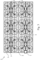
- Induced-draft air-cooled heat exchanger systems comprise a plurality of fan assemblies, generally ordered in multiple adjacent rows, corresponding to multiple adjacent rows of heat exchangers, as schematically illustrated on Fig.1a .
- Each of the fan assemblies typically comprise a fan hub, fan blades and one or more driving components for rotating the fan blades.
- the one or more driving components comprise for example a gearbox, a motor, and a drive shaft connecting the motor to the gearbox.
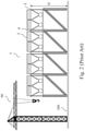
- Fig.2 For performing maintenance activities, large overhead tower cranes located on the ground floor are used to remove components of the fan assemblies, as schematically illustrated on Fig.2 .
- This method of removing components of fan assemblies however limits the number of rows of fan assemblies that can adjacently be placed together, and hence limits the size of the heat exchanger system, due to the fact that fan assemblies located in central rows cannot or difficultly be reached with an overhead crane.
- a driving component is for example a motor, a gearbox or a drive shaft coupled between the motor and the gearbox.
- a method for removing components of fan assemblies of an induced-draft air-cooled heat exchanger system is provided.
- Each fan assembly of the heat exchanger system comprises any of the following non-limiting list of components: a fan blade, a fan hub and one or more driving components for rotating the fan blades.
- the induced-draft heat exchanger system comprises a covered fan deck located at a given altitude from a ground floor and the fan deck comprises a plurality of openings, each opening being fringed by a fan bell that is associated to one of the fan assemblies of the heat exchanger system. Inside each fan bell, a fan bridge is extending towards a center of the fan bell.
- the method according to the present disclosure comprises:
- the method further comprises:
- each of the components of the fan assemblies of any of the streets is accessible without the need of any large overhead tower crane, independently of the number of rows of fan assemblies of the heat exchanger system.
- each of the fan bells is formed by a plurality of fan bell segments and the method comprises:
- a system for removing components of one or more fan assemblies of an induced-draft air-cooled heat exchanger system comprises a) a mobile crane for driving on a covered deck of the induced-draft air-cooled heat exchanger system and/or for driving on fan bridges located inside fan bells associated to the fan assemblies, and b) driving means for driving the mobile crane, preferably the driving means are configured for driving the mobile crane in a forward and backward direction.
- the mobile crane according to the present disclosure comprises a first siderail assembly comprising a first row of wheels extending along a first rail axis, a second siderail assembly comprising a second row of wheels extending along a second rail axis, and wherein the second siderail assembly is spaced from the first siderail assembly, and a support frame structure mounted on the first and second siderail assembly.
- the support frame structure comprises i)a first side frame, wherein a bottom portion of the first side frame is attached to the first siderail assembly, ii) a second side frame, wherein a bottom portion of the second side frame is attached to the second siderail assembly, and iii)an overhead spacing structure coupling a top portion of the first side frame to a top portion of the second side frame.
- the mobile crane further comprises a hoist support beam and a hoist, wherein the hoist is rigidly or moveably coupled to the hoist support beam.
- the hoist support beam comprises at least a first beam portion and a second beam portion, and wherein the first beam portion is rigidly attached to the overhead spacing structure and the second beam portion is cantilevered with respect to the support frame structure.
- a rigid and stable mobile crane is obtained. It is important to have a stable mobile crane as heavy winds can occur on the fan deck.
- a spacing is maintained between the first and second side rail assembly such that a cart can be placed between the first and second side rail assembly and a component lifted with the mobile crane can be lowered in the cart for further transportation.
- the first and said second rail axis of the mobile crane are parallel.
- the overhead spacing structure of the mobile comprises means for relatively moving the first side frame with respect to the second side frame along a lateral axis transverse to the first and second rail axes of respectively the first and second siderail assembly. In this way, a distance between the first and the second rail axis measured along the lateral axis is variable between a first distance and a second distance, wherein the second distance is smaller than the first distance.
- the lateral width of the mobile crane is variable from a maximum lateral width to a minimum lateral width.
- the minimum lateral width the mobile crane can follow a trajectory path between two adjacent fan bells separated by a narrow distance, of for example less than one meter.
- the mobile crane can be set to its maximum lateral size, for providing a better stability.
- the system for removing components of one or more fan assemblies of an induced-draft air-cooled heat exchanger system further comprises c) a cart, and wherein a width of the cart is configured such that the cart can be driven between the first and the second siderail assemblies.
- the cart can be used in combination with the mobile crane to transport smaller but heavy components such as for example the motor or the fan gearbox.
- the lateral stroke defined as the difference between the maximum and minimum lateral width is between 30 cm and 90 cm, preferably between 40 cm and 80 cm and more preferably between 50 cm and 70 cm.
- the height of the mobile crane can be adjusted between a maximum height H max and a minimum height H min .
- a height stroke defined as the difference between the maximum H max and the minimum H min height of the mobile crane is generally between 50 cm and 200 cm, preferably between 80 cm and 160 cm, more preferably between 90 cm and 150 cm.
- the system according to the present disclosure comprises a first siderail extension for extending the first siderail assembly and a second siderail extension for extending the second siderail assembly, and wherein at least one additional wheel is coupled to each of the first and second siderail extensions.
- a method for removing components of fan assemblies of an induced-draft air-cooled heat exchanger system comprises a plurality of fan assemblies 3 ordered in rows, as schematically shown in Fig.1a where a top view of an example of an induced-draft air-cooled heat exchanger system 1 is schematically shown.
- a row of fan assemblies on top of heat exchangers generally corresponds to what is named a heat exchanger street 2 and multiple streets 2 are placed adjacently to each other to form the heat exchanger system 1.
- five streets 2 are shown, and wherein each street comprises a row of seven fan assemblies.
- Each fan assembly 3 comprises a number of components such as fan blades coupled to a fan hub, and one or more driving components for rotating the fan blades.
- Fig.7 a cross-sectional view of an embodiment of a portion of a fan assembly is shown, illustrating two fan blades 61 coupled to a fan hub 62.
- a rotation diameter of the fan assembly is in a range between 8 and 15 meters, for example 12 meter.
- the fan hub 62 is generally a circular frame and each fan blade 61 is rigidly coupled with one end to the fan hub 62.
- the diameter of the fan Hub DH is between 1 and 3 meters, for example 2 meter.
- the blade span LB is between 3 and 7 meters, for example 5 meter.
- an induced-draft heat exchanger system 1 comprises a covered fan deck 4 located at a given altitude H with respect to a ground floor 300.
- the fan deck 4 comprises a plurality of openings, generally circular openings, fringed by a fan bell 5.
- Each fan bell is associated to one fan assembly. Inside each fan bell 5, the fan blades coupled to the fan hub are rotatably mounted.
- the fan bell 5 is composed of a plurality of fan bell segments attached together to form the fan bell.
- a fan bridge 8 is provided that is extending towards a center of the fan bell, generally corresponding to a center of the opening in the fan deck being surrounded by the fan bell.
- No fan assembly is shown in Fig.1b , only a portion of the fan deck 4, the fan bell 5 and the fan bridge 8 are schematically shown for illustrative purposes.
- Such a fan bridge 8 is to be construed as a walking bridge, generally provided to allow inspection of the fan by maintenance personnel.
- a fan bell segment 5a in front of the fan bridge is provided with a hatch 5b or a small door.
- the fan bridge comprises additional safety railings, not shown on the fig.1b , to allow a safe access to the fan.
- components of the fan assembly need to be removed from the fan deck and be replaced by spare parts.
- components of the fan assembly are: the fan blades, the fan hub and one or more driving components for rotating the blades.
- the components for rotating the blades are for example a gear box, a drive shaft and a motor.
- the method according the present disclosure uses a mobile crane that both can drive on the fan deck 4 and/or on the fan bridges 8.
- the driving means comprise a motor coupled to a drive shaft, for removing the motor it is not necessary to drive with the mobile crane on the fan bridge.
- for removing for example a fan blade it is necessary to drive with the mobile crane on the fan bridge, as will be discussed below in more detail.
- FIG.4 An exemplary embodiment of a mobile crane 10 for driving on the fan deck 4 and fan bridges 8 is shown on Fig.4 and will be discussed in more detail below.
- the hoist 40 of the mobile crane is then used to lift and remove any of the components of the fan.
- the mobile crane drives on the fan deck 4 following a trajectory path 6.
- the trajectory path is, as illustrated on Fig.3 , running at least partly, between adjacent fan bells 5.
- the trajectory path 6 of the mobile crane is indicated on Fig.3 by white arrows.
- a heat exchanger system comprising twenty four fan assemblies is shown.
- the white arrows on Fig.3 illustrate a direction of motion of a mobile crane, when following the trajectory 6, towards an edge area 7 of the fan deck.
- the mobile crane can also follow the trajectory in the opposite direction from the edge area 7 to anyone of the fan assemblies of the heat exchanger system.
- the fan bell 5 is composed of a plurality of fan bell segments
- a first fan bell segment of the first fan bell needs to be removed.
- the fan bridge is basically an access for maintenance personnel, and generally only a hatch 5b or small door is provided in the first fan bell segment of the fan bell in front of the fan bridge, as illustrated on Fig.1b .
- the first fan bell segment that is located in front of the entrance of the fan bridge is to be removed.
- each of first fan bell segments of each of the fan bells can be reached with the mobile crane and the mobile crane can have access to each of the respective fan bridges.
- the mobile crane when the mobile crane is driving along the trajectory path 6 it will have to drive at least between two adjacent fan bells.
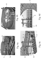
- the mobile crane 10 can be used to lift the first fan bell segment 5a, as illustrated on Fig.6a .
- the first fan bell segment 5a can be removed in a manual way by maintenance personnel.
- the removed first fan bell segment 5a can either be placed in a storage area on the fan deck or the first segment can be transported to the edge area of the fan deck. From the edge area, the first fan bell segment can be lowered to the ground floor by either using a permanent hoist structure located in the edge area of the fan deck, or alternatively using a tower crane located on the ground floor.
- the method according to the present disclosure comprises a step of driving the mobile crane on a first fan bridge located inside a first fan bell associated to a first fan assembly.
- the motor is coupled to a drive shaft, the motor is located outside the fan bell, i.e. in the neighbourhood of the fan bell. For removing a motor located outside the fan bell, it is then sufficient to drive with the mobile crane to the neighbourhood of the fan bell.
- the mobile crane 10 is used for lifting the first component of the first fan assembly.
- the first component can be any of the non-limiting list of components of the fan assembly as mentioned above.
- the first component is further transported towards the edge area 7 of the fan deck by either driving the mobile crane, while supporting the first component, or alternatively, using the mobile crane for placing the first component on a cart and driving the cart to the edge area.
- transportation with a cart is schematically illustrated for respectively a gearbox and a motor.
- the permanent hoist structure located in the edge area of the fan deck is used for lowering the first component from the fan deck down to the ground floor.
- a tower crane located on the ground floor is used for lowering the first component located in the edge area of the fan deck down to the ground floor.
- a safety railing 4a is shown surrounding the fan deck 4.
- a further component of the first fan assembly can be removed following the same method and/or one or more components of a second fan assembly can be removed.
- One of the problems of using a mobile crane on the fan deck is that the distance between fan bells 5 can be very narrow, for example less than one meter, e.g. 80 cm or 90 cm. Therefore, a dedicated mobile crane 10 with a small lateral dimension is to be used that at the same time is configured for lifting on the one hand the various fan drive components having a weight of more than one ton and on the other hand lifting fan components such as fan blades having a span length LB of several meter long, for example more than 5 meter long.
- the mobile crane has also to be stable as strong winds can occur on the fan deck.
- the mobile crane 10 needs also to be adapted to spread the load on the fan deck 4.
- the fan deck is basically a cover, as discussed in the introduction part, to make sure that the induced-draft air is only escaping through the fan bells.
- the amount of steel for building the fan deck is limited to the minimum necessary and the fan deck is generally not designed to support heavy loads such as a mobile crane for lifting components of more than one ton and wherein the mobile crane has a weight of a few ton.
- the fan deck plating and structure are designed for a maximum concentration load, and hence the mobile crane needs to be designed accordingly.
- the fan bridge which is generally a grating frame, is in the first place designed to provide access to workers for inspection or small maintenance work of the fans.
- the loads on the fan bridge are also limited and the mobile crane needs to be designed accordingly.
- the method disclosed above for removing components from the fan assembly can also be applied in a reverse order for installing new or repaired components.
- the method for installing a new component comprises:
- the method before driving with the mobile crane on the fan bridge associated to the second fan assembly, the method comprises removing a fan bell segment of the fan bell associated to the second fan assembly. In this way, access is provided to the mobile crane for driving on the fan bridge associated to the second fan assembly.
- the method according to the present disclosure provides for removing a first fan blade 61 of a first fan assembly of the plurality of fan assemblies of the air-cooled heat exchanger by performing steps of:
- a mobile crane positioned on the fan bridge of the first fan assembly is shown, and wherein the mobile crane is lifting the first fan blade for removal.
- the method comprises a step of tilting the first fan blade in an upward position. This upward tilting facilitates the lifting of the first fan blade with the hoist of the mobile crane and the further transportation of the first fan blade with the mobile crane.
- the method according to the present disclosure provides for removing a first fan hub of the first fan assembly by performing steps of:
- the hub spreader bar 42 is a tool that facilitates the lifting of the fan hub and is illustrated on Fig.6c and Fig.15 .
- the fan hub has been rotated by 90° when compared to the position of the fan hub shown in Fig.6c .
- This position of the fan hub after the 90° rotation facilitates the further transport of the fan hub by for example attaching the rotated fan hub 62 to the fan hub support structure 110 of the cart 100, as illustrated on Fig.15 .
- the one or more driving components of each of the fan assemblies comprises a gearbox, a drive shaft and a motor.
- the drive shaft is coupled with a first end to the gearbox and coupled with an opposite second end to the motor.
- the method further comprises steps for removing the motor, the gearbox and the drive shaft.
- a first motor of the first fan, coupled to a first drive shaft is removed by performing steps of:
- a removal of a motor is partly illustrated.
- the motor 63 is located on the fan deck 4 in front of the fan bridge 8.
- the mobile crane 10 is partly positioned on the fan bridge and partly on the fan deck.
- a cart 100 is placed between the first and second side rail assemblies of the mobile crane.
- the mobile crane 10 is then used for placing the motor in the cart by lowering the motor.
- the cart 100 is pulled by an electrical tractor 150 for transporting the motor to the edge area of the fan deck.
- removing the first drive shaft of the first fan assembly is performed by steps of:
- the present method provides for removing a first gearbox of the first fan assembly by performing steps of:
- a mobile crane 10 driven on the fan bridge 8 for lifting a gear box 64 is illustrated.
- Fig.16a and Fig.16b the removal of the gearbox 64 is further illustrated.
- a cart 100 is placed between the first and second side rail assembly of the mobile crane 10. The mobile crane 10 is then used for placing the gearbox in the cart by lowering the gearbox with the mobile crane. Thereafter, the cart 100 is pulled with an electrical tractor 150 for transporting the gearbox 64 to the edge area of the fan deck.
- a first segment 5a of the fan bell 5 that is blocking the access to the fan bridge 8, is to be removed.
- the method comprises performing steps of:
- a mobile crane 10 lifting the first segment 5a of the first fan is illustrated.
- a system for removing components of one or more fan assemblies of an induced-draft air-cooled heat exchanger system comprises a) a mobile crane for driving on the covered deck of the induced-draft air-cooled heat exchanger system and for driving on the fan bridges associated to the fan assemblies, and b) driving means for driving the mobile crane.
- the driving means are removably connectable to the mobile crane and the mobile crane has no proper motorization directly coupled to the wheels of the mobile crane.
- the driving means for driving the mobile crane comprises for example an electric tractor for pushing or pulling the mobile crane.
- the mobile crane comprises a drawbar 80 for coupling the electric tractor to the mobile crane, preferably, as illustrated on Fig.4 , the drawbar 80 is connected to the first and second siderail assembly of the mobile crane.
- the electrical tractor can be removed from the crane when the crane does not need to be moved and/or the electrical tractor can be used for other purposes, such as pushing or pulling a cart, as will be further discussed below.
- the driving means are not removably attached to the mobile crane but are fixed to the mobile crane.
- the driving means comprise a motorization, such as for example an electrical motor coupled to at least two wheels of the mobile crane for driving the mobile crane.
- the driving means for driving the mobile crane are configured for driving the mobile crane in a forward and in a backward direction.
- the system for removing components further comprises a cart having a drawbar for coupling with an electrical tractor.
- the electrical tractor for driving the cart is the same as the electrical tractor for driving the mobile crane, in other embodiments a second electrical tractor can be used to drive the cart on the fan deck, in addition to a first electrical tractor for driving the mobile crane.
- FIG.4 An isometric view of an example of an embodiment of a mobile crane 10 of the system for removing components of one or more fan assemblies according to the present disclosure is shown in Fig.4 .
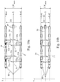
- a top view and a front view of the mobile crane shown on Fig.4 is shown respectively on Fig.10a and Fig.11a .
- the mobile crane 10 comprises a first siderail assembly 11 comprising a first row of wheels 21 extending along a first rail axis RA1 and a second siderail assembly 12 comprising a second row of wheels 22 extending along a second rail axis RA2.
- the second siderail assembly 12 is spaced from the first siderail assembly 11.
- the first and second siderail assemblies of the mobile crane each at least comprise two wheels.
- six wheels are coupled to each of the first and second siderail.
- the number of wheels on each of the first and second siderail assembly is between two and ten, depending on the load characteristics of the fan deck.
- each of the siderail assemblies comprises a rail and a row of casters attached to the rail, wherein the caster comprises a bracket and a wheel.
- the casters are swivel casters configured such that the wheels in the casters can rotate 360°.
- the rail of the first and second siderail assembly is respectively parallel with the first RA1 and second RA2 rail axis.
- the first and second siderail assemblies can be construed as a base of the mobile crane, also named chassis.
- the mobile crane 10 further comprises a support frame structure mounted on top of the first and second siderail assembly.
- the support frame structure comprises i) a first side frame 16, wherein a bottom portion of the first side frame is attached to the first siderail assembly 11, ii) a second side frame 17, wherein a bottom portion of the second side frame is attached to the second siderail assembly 12, and iii)an overhead spacing structure 30 coupling a top portion of the first side frame 16 to a top portion of the second side frame 17.
- the support frame structure comprising the first and second side frame and the overhead spacing structure, can be construed as a frame that couples the first and second siderail while maintaining a free space between the first 16 and second 17 side frame.
- the first 16 and second 17 side frames can be construed as a left-side and a right-side frame of the mobile crane.
- the mobile crane further comprises, as for example illustrated on Fig.4 and Fig.9a , a hoist support beam 50 and a hoist 40 for lifting a load.
- the host support beam 50 comprises a first beam portion 50a that is rigidly attached to the overhead spacing structure 30, and preferably a second beam portion 50b that is cantilevered with respect to the support frame structure.
- the hoist 40 is either rigidly or moveably coupled to the hoist support beam. If the hoist is located in the first position at the end of the second beam portion, components of the fan such as for example the fan hub, as illustrated on Fig.6c , can be lifted as a result of the cantilevered hoist. Depending on the detailed design of the fan, the fan hub can have a diameter of one to a few meters. Therefore, the second beam portion 50b of the hoist support beam is at least one meter long.
- the hoist 40 is illustrated to be located at the first hoist position, i.e. at the end of the hoist support beam.
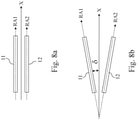
- the first 11 and second 12 side rail assemblies are running parallel with a longitudinal axis X, i.e. the first RA1 and the second RA2 rail axis of the first and second side rail assemblies are parallel.
- Fig.8a a top view of the first 11 and second 12 side rail assemblies are shown and wherein the first RA1 and the second RA2 rail axes are running parallel with the longitudinal axis X.
- the first and second side rail assemblies are not running parallel, and the corresponding first and second axis are not parallel.
- Fig.8b where the first RA1 and second RA2 axis of respectively the first and second side rail assemblies are rotated with an angle ⁇ with respect to the longitudinal axis X.
- the hoist support beam 50 is extending in a direction parallel with the longitudinal axis X.
- the hoist support beam is for example an I-profile beam.
- the hoist support beam comprises one hoist position, i.e. the hoist position located at the end of the second portion of the overhead beam.
- multiple hoist positions are provided along the first and/or second portion of the hoist support beam. With hoist positions available on the first portion of the hoist support beam, the hoist is no longer in a cantilever position and heavier loads can be lifted.
- the hoist 40 is positioned in the first portion of the overhead beam 50, in non-cantilevered position for lifting a motor 63
- Fig.15 the hoist 40 is positioned at the end of the second portion of the overhead beam 50 in a cantilevered position for lifting for example a fan hub 62.
- the hoist 40 is moveably attached to the hoist support beam 50 for moving along the hoist support beam between a first hoist position and a second hoist position.
- the hoist 40 of the mobile crane 10 comprises a trolley with a hook 41 to attach an object to be lifted.
- the mobile crane comprises a first siderail extension for extending the first siderail assembly along the first rail axis RA1 and a second siderail extension for extending the second siderail assembly along the second rail axis RA2.
- at least one additional wheel is coupled to each of the first and second siderail extensions.
- the siderail extension can be removed to better access the component to be reached when the hoist is in a cantilevered position.
- the siderail extensions can be added to facilitate the movement and stability of the crane while driving.
- the overhead spacing structure 30 is a metal frame comprising cross beam members for connecting the first and the second side frames.
- the spacing structure is a fixed structure to maintain a fixed width between the first side and the second side frame.
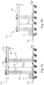
- the overhead spacing structure 30 comprises means for relatively moving the first side frame with respect to the second side frame along a lateral axis Y transverse to the first R1 and second R2 axis of respectively the first and second siderail assembly such that a distance between the first R1 and second R2 rail axis measured along the lateral axis Y is variable between a first distance D1 and a second distance D2, wherein the second distance D2 is smaller than the first distance D1.
- a lateral width of the mobile crane measured along the lateral axis Y is variable between a maximum lateral width LW max and a minimum lateral width LW min .
- the first D1 and second D2 distance are illustrated for example on respectively Fig.10a and Fig.10b .
- the minimum lateral width LW min and maximum lateral width LW max correspond to a folded and an unfolded position of the mobile crane.
- the lateral width is respectively set to the maximum LW max and to the minimum LW min lateral width.
- the mobile crane when the mobile crane has to move between two fan bells of two fan assemblies, the mobile crane is generally in a folded position.
- the difference between the lateral width when in respectively the unfolded and folded position, i.e. the difference between the maximum and minimum lateral width is further named lateral stroke.
- the lateral stroke is between 30 cm and 90 cm, preferably between 40 cm and 80 cm and more preferably between 50 cm and 70 cm.
- the lateral stroke is for example 60 cm and the minimum and maximum lateral width correspond for example to respectively, 84 cm and 144 cm.
- the means of the overhead spacing structure for relatively moving the first side frame 16 with respect to the second side frame 17 comprises cross beams configured for varying the distance between the first and second side from the first to the second distance and vice versa.
- the cross beams having a variable length are for example telescopic cross beams.
- a telescopic cross beam comprises a first and a second beam member wherein a first beam member glides inside or glides alongside a second member so as to vary the overall length of the cross-beam member.
- the overhead spacing structure 30 of the mobile crane comprises a first spacing member 31 having a first pair of cross beams 31a,31b and a second spacing member 32, separated from the first spacing member, having a second pair of cross beams 32a,32b.
- a top view of a mobile crane having a spacing structure 30 comprising a first 31 and a second 32 spacing member is illustrated on Fig.10a .
- the first pair 31a,31b and second pair 32a,32b of cross beams of respectively the first 31 and second 32 spacing member are configured for varying the distance between the first 16 and second 17 side frame.
- each cross beam of the pair of cross beams is configured for traveling half of the maximum stroke defined above.
- the first 31 and second 32 spacing member comprises respectively a first 31c and a second 32c coupling member.
- the first coupling member 31c is configured such that the cross beams 31a,31b of the first pair of cross beams can move with respect to the first coupling member in the lateral direction Y.
- the second coupling member 32c is configured such that the cross beams 32a,32b of the second pair of cross beams can move with respect to the second coupling member.
- the relative movement of the first side frame with respect to the second side frame is generally automated.
- the means for relatively moving the first side frame with respect to the second side frame comprise one or more hydraulic cylinders 35 for actuating the telescopic cross beam members.
- telescopic beams are used wherein a first member is forming a rail and a second member is forming a beam configured for gliding over the rail formed by the first member.
- the gliding of the second member over the first rail member can be automated by for example an electrical motor.
- the drawbar 80 is adaptable to the lateral width of the mobile crane, as illustrated on Fig.10a and Fig.10b .
- the hoist support beam 50 is centrally located between the first 16 and the second 17 side frame.
- the means for relatively moving are configured such that the hoist support beam remains centrally located when the mobile crane is in the folded and unfolded position.
- each cross beam member of a pair of cross beams of the overhead spacing structure is synchronized such that when varying the lateral width of the mobile crane, the hoist support beam 50 maintains in its central location between the first and second side frame, independent of the distance between the first and the second side frame.
- each of the first 16 and second 17 side frames are formed by connecting, e.g. by welding and/or bolting, a plurality of metal beams.
- the first side frame 16 comprises a first support beam 16a and a second support beam 16b spaced from the first support beam.
- the first and second support beams are extending in a direction parallel with a Z-axis perpendicular to the longitudinal axis X and the lateral axis Y.
- the first support beam 16a is attached with a lower end to the first siderail assembly 11 and with an upper end to the first spacing member 31, and the second support beam 16b is attached with a lower end to the first siderail assembly 11 and with an upper end to the second spacing member 32.
- the second side frame 17 comprises a third support beam 17a and a fourth support beam 17b spaced from the third support beam and wherein the third and fourth support beams are extending in a direction parallel with the Z-axis, and wherein the third support beam 17a is attached with a lower end to the second siderail assembly 12 and with an upper end to the first spacing member 31, and the fourth support beam 17b is attached with a lower end to the second siderail assembly 12 and with an upper end to the second spacing member 32.
- the attachments of the support beams to the siderail assemblies and spacing member can be realized by welding or bolting.
- first 16a and second 16b support beams are perpendicular to the first rail axis R1
- third 17a and fourth 17b support beams are perpendicular to the second rail axis R2.
- the wheels that are attached to the siderail assemblies are for example wheels having rubber tyres for facilitating movement on a deck of an air-cooled condenser.
- a counterweight is provided to compensate the weight of the component being lifted when the hoist is in a cantilevered hoist position.
- a first counterweight 71 is supported by an end portion of the first siderail assembly and a second counterweight 72 is supported by an end portion of the second siderail assembly.
- a counterweight can be composed of a plurality of plates.
- the height of the mobile crane can be adjusted between a maximum height H max and a minimum height H min .
- Fig.9a and Fig.9b side views of a mobile crane with variable height are shown, and wherein the mobile crane is respectively set to a maximum height H max and set to a minimum height H min .
- varying a height of the mobile crane has to be construed as varying a height of the hoist support beam 50 between a maximum and minimum height with respect to the first and the second siderail assemblies.
- the minimum height H min is smaller than the maximum height H max .
- the height is measured along a vertical axis Z perpendicular to the lateral axis Y.
- the maximum H max and minimum H min height can for example be measured between a side of the hoist support beam and a side of the siderail assemblies, as illustrated on Fig.9a, Fig.9b , Fig.11a and Fig.11b .
- a measurement between any other reference points of the hoist support beam and the siderail assemblies can be selected to define a height of the mobile crane.
- the first side frame and the second side frame each comprise one or more support beams variable in length and configured for varying a height of the hoist support beam 50 with respect to first and second siderail assemblies.
- the one or more support beams variable in length are telescopic beams.
- a height stroke defined as the difference between the maximum H max and the minimum H min height of the mobile crane is generally between 50 cm and 200 cm, preferably between 80 cm and 160 cm, more preferably between 90 cm and 150 cm.
- the system for removing components one or more fan assemblies comprises an electrical tractor for pulling or pushing the mobile crane and/or for pushing or pulling the cart.
- the electrical tractor typically comprises a plurality of wheels and a driving means.
- the electric tractor is for example operational with rechargeable batteries. Hence, to charge the batteries, the electric tractor must for example be plugged in a 3 phase 480V 60Hz plug. For charging the electrical tractor while located on the fan deck, an electrical plug located on the fan deck can be used.
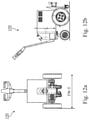
- a lateral width TW-T of the electrical tractor has to be sufficiently narrow in order to be able to easily drive with the electrical tractor on the trajectory path between the adjacent fan bells, and, in some embodiments, to drive with electrical tractor between the first and second siderail assemblies of the mobile crane.
- the lateral width TW-T of the tractor has to be construed as the maximum lateral dimension of the cart measured in a lateral direction.
- the lateral size of the electrical tractor is determined by the track width TW-T of two of the wheels of the tractor.
- the track width is defined such that the electrical tractor can drive between the first and the second siderail assembly of the mobile crane.
- the maximum track width TW-T of the electrical tractor, illustrated on Fig.12a is preferably between 50 cm and 100 cm, more preferably between 60 cm and 90 cm.
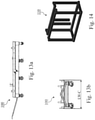
- FIG.13a and Fig.13b A side and front view of an example of a cart 100 of the system for removing components of one or more fan assemblies is respectively shown in Fig.13a and Fig.13b .
- components of the fan When components of the fan have been lifted with the mobile crane 10, they can be positioned on the cart 100 and the cart can then be used to transport the components of the fan towards the edge area of the fan bridge.
- the cart 100 comprises a support deck or support beams to support a component of the fan to be transported and the cart comprises at least three wheels, preferably at least four wheels, and more preferably at least six wheels.
- the wheels are for example caster wheels of the swivel and/or fixed type.
- the cart has a lateral width LW-C, illustrated on Fig.13b , between 60 cm and 120 cm, more preferably between 70 cm and 90 cm.
- the lateral width LW-C of the cart must be construed as the maximum lateral dimension of the cart measured in a lateral direction.
- the lateral width of the cart is configured such that the cart can be driven and placed between the first and the second siderail assemblies of the mobile crane, as illustrated on Fig.15 .
- a component of a fan such as for example fan hub 62, as shown on Fig.15 , can in first step be removed with the mobile crane and in a second step be placed on the cart 100 for further transportation to for example the permanent hoist located on the fan deck.
- the cart comprises support elements for carrying specific components of the fan.
- a hub support structure 110 is shown that can be placed on the cart for supporting a fan hub 62.
- the fan hub is attached to the hub support structure 110.
- a fan hub 62 is supported by the hub support structure 110 and the hub support structure 110 is attached to the cart 100.
- a hub spread bar 42 is forming an interface between the hoist 40 of the mobile crane and the fan hub.
- the hub spread bar 42 facilitates the lifting and lowering of the fan hub with the mobile crane.
Landscapes
- Engineering & Computer Science (AREA)
- Mechanical Engineering (AREA)
- General Engineering & Computer Science (AREA)
- Civil Engineering (AREA)
- Structural Engineering (AREA)
- Structures Of Non-Positive Displacement Pumps (AREA)
Priority Applications (2)
| Application Number | Priority Date | Filing Date | Title |
|---|---|---|---|
| EP20195780.0A EP3967960A1 (fr) | 2020-09-11 | 2020-09-11 | Procédé et système d'élimination de composants d'un ensemble de ventilateur d'un système d'échangeur de chaleur induit par tirage |
| PCT/EP2021/074254 WO2022053388A1 (fr) | 2020-09-11 | 2021-09-02 | Procédé et système de retrait de composants d'un ensemble ventilateur dans un système d'échangeur de chaleur à tirage induit |
Applications Claiming Priority (1)
| Application Number | Priority Date | Filing Date | Title |
|---|---|---|---|
| EP20195780.0A EP3967960A1 (fr) | 2020-09-11 | 2020-09-11 | Procédé et système d'élimination de composants d'un ensemble de ventilateur d'un système d'échangeur de chaleur induit par tirage |
Publications (1)
| Publication Number | Publication Date |
|---|---|
| EP3967960A1 true EP3967960A1 (fr) | 2022-03-16 |
Family
ID=72474125
Family Applications (1)
| Application Number | Title | Priority Date | Filing Date |
|---|---|---|---|
| EP20195780.0A Withdrawn EP3967960A1 (fr) | 2020-09-11 | 2020-09-11 | Procédé et système d'élimination de composants d'un ensemble de ventilateur d'un système d'échangeur de chaleur induit par tirage |
Country Status (2)
| Country | Link |
|---|---|
| EP (1) | EP3967960A1 (fr) |
| WO (1) | WO2022053388A1 (fr) |
Citations (5)
| Publication number | Priority date | Publication date | Assignee | Title |
|---|---|---|---|---|
| US5947308A (en) * | 1997-07-03 | 1999-09-07 | Markelz; Paul H. | Bridge erection system |
| NL1014553C2 (nl) * | 2000-03-03 | 2001-09-04 | Lagerwey Windturbine B V | Hijsinrichting en werkwijze voor samenbouwen van een windmolen, alsmede een windmolen. |
| WO2017202730A1 (fr) * | 2016-05-25 | 2017-11-30 | Spx Dry Cooling Belgium | Générateur à condensateur refroidi par air et procédé |
| WO2018132832A2 (fr) * | 2017-01-13 | 2018-07-19 | Bridge And Track Crane Llc D/B/A Rcrane | Systèmes et procédés associés à une grue mobile |
| EP3287732B1 (fr) | 2016-08-24 | 2019-10-02 | SPG Dry Cooling Belgium | Condenseur refroidi par air à tirage induit |
-
2020
- 2020-09-11 EP EP20195780.0A patent/EP3967960A1/fr not_active Withdrawn
-
2021
- 2021-09-02 WO PCT/EP2021/074254 patent/WO2022053388A1/fr not_active Ceased
Patent Citations (5)
| Publication number | Priority date | Publication date | Assignee | Title |
|---|---|---|---|---|
| US5947308A (en) * | 1997-07-03 | 1999-09-07 | Markelz; Paul H. | Bridge erection system |
| NL1014553C2 (nl) * | 2000-03-03 | 2001-09-04 | Lagerwey Windturbine B V | Hijsinrichting en werkwijze voor samenbouwen van een windmolen, alsmede een windmolen. |
| WO2017202730A1 (fr) * | 2016-05-25 | 2017-11-30 | Spx Dry Cooling Belgium | Générateur à condensateur refroidi par air et procédé |
| EP3287732B1 (fr) | 2016-08-24 | 2019-10-02 | SPG Dry Cooling Belgium | Condenseur refroidi par air à tirage induit |
| WO2018132832A2 (fr) * | 2017-01-13 | 2018-07-19 | Bridge And Track Crane Llc D/B/A Rcrane | Systèmes et procédés associés à une grue mobile |
Also Published As
| Publication number | Publication date |
|---|---|
| WO2022053388A1 (fr) | 2022-03-17 |
Similar Documents
| Publication | Publication Date | Title |
|---|---|---|
| US10781798B2 (en) | Nacelle component for a wind turbine and method for mounting a nacelle component | |
| US10947959B2 (en) | Method and apparatus of performing maintenance on a wind turbine component | |
| CN103620213B (zh) | 用于设立、维护和拆卸风能设备的方法 | |
| CN103459833B (zh) | 风力涡轮机 | |
| US8578680B2 (en) | Tower construction method and apparatus | |
| CN110104564A (zh) | 一种桥式起重机总装工艺 | |
| US11105312B1 (en) | Penstock internal maintenance system and process of assembling, anchor unit | |
| ES2728789B2 (es) | Modulo movil para el izado de torres telescopicas y procedimiento de izado de torres telescopicas | |
| EP3967960A1 (fr) | Procédé et système d'élimination de composants d'un ensemble de ventilateur d'un système d'échangeur de chaleur induit par tirage | |
| JP5715832B2 (ja) | 塔状構造物のメンテナンス方法 | |
| CN114180467B (zh) | 一种拼装式起吊装置 | |
| CN115367617A (zh) | 卸船机用小车轨道更换装置及方法 | |
| CN218404875U (zh) | 一种接触轨安装移动平台 | |
| CN107539921A (zh) | 一种可拆卸的工地临时升降机构 | |
| KR20140015957A (ko) | 풍력 발전기의 나셀 내부 기계 요소 이송 장치 | |
| CN222594594U (zh) | 一种适用于桥梁检修车轨道安装的工装结构 | |
| CN210141134U (zh) | 一种隧道缺陷整治移动台架 | |
| CN224212293U (zh) | 更换装置 | |
| US7367461B2 (en) | Movable girder mounted jib | |
| CN220432127U (zh) | 一种变高变宽自移动车载提运装备 | |
| CN217126729U (zh) | 一种轨道运载小车 | |
| ES2778652T3 (es) | Método y sistema de mantenimiento para receptor solar | |
| CN217997830U (zh) | 一种轨道式平移架梁装置 | |
| US20240228241A9 (en) | Lifting systems and methods for performing operations on a structure | |
| CN121875179A (zh) | 用于桥梁结构检测的无人检测设备及其检测方法 |
Legal Events
| Date | Code | Title | Description |
|---|---|---|---|
| PUAI | Public reference made under article 153(3) epc to a published international application that has entered the european phase |
Free format text: ORIGINAL CODE: 0009012 |
|
| STAA | Information on the status of an ep patent application or granted ep patent |
Free format text: STATUS: THE APPLICATION HAS BEEN PUBLISHED |
|
| AK | Designated contracting states |
Kind code of ref document: A1 Designated state(s): AL AT BE BG CH CY CZ DE DK EE ES FI FR GB GR HR HU IE IS IT LI LT LU LV MC MK MT NL NO PL PT RO RS SE SI SK SM TR |
|
| STAA | Information on the status of an ep patent application or granted ep patent |
Free format text: STATUS: THE APPLICATION IS DEEMED TO BE WITHDRAWN |
|
| 18D | Application deemed to be withdrawn |
Effective date: 20220917 |