EP3968268A1 - Procédé et dispositif de réglage de luminosité d'image, support de stockage et dispositif électronique - Google Patents
Procédé et dispositif de réglage de luminosité d'image, support de stockage et dispositif électronique Download PDFInfo
- Publication number
- EP3968268A1 EP3968268A1 EP20801932.3A EP20801932A EP3968268A1 EP 3968268 A1 EP3968268 A1 EP 3968268A1 EP 20801932 A EP20801932 A EP 20801932A EP 3968268 A1 EP3968268 A1 EP 3968268A1
- Authority
- EP
- European Patent Office
- Prior art keywords
- luminance
- image
- threshold
- target
- original image
- Prior art date
- Legal status (The legal status is an assumption and is not a legal conclusion. Google has not performed a legal analysis and makes no representation as to the accuracy of the status listed.)
- Pending
Links
Images





Classifications
-
- G—PHYSICS
- G06—COMPUTING OR CALCULATING; COUNTING
- G06T—IMAGE DATA PROCESSING OR GENERATION, IN GENERAL
- G06T5/00—Image enhancement or restoration
- G06T5/90—Dynamic range modification of images or parts thereof
-
- G—PHYSICS
- G09—EDUCATION; CRYPTOGRAPHY; DISPLAY; ADVERTISING; SEALS
- G09G—ARRANGEMENTS OR CIRCUITS FOR CONTROL OF INDICATING DEVICES USING STATIC MEANS TO PRESENT VARIABLE INFORMATION
- G09G5/00—Control arrangements or circuits for visual indicators common to cathode-ray tube indicators and other visual indicators
- G09G5/10—Intensity circuits
-
- G—PHYSICS
- G06—COMPUTING OR CALCULATING; COUNTING
- G06T—IMAGE DATA PROCESSING OR GENERATION, IN GENERAL
- G06T1/00—General purpose image data processing
- G06T1/20—Processor architectures; Processor configuration, e.g. pipelining
-
- G—PHYSICS
- G06—COMPUTING OR CALCULATING; COUNTING
- G06T—IMAGE DATA PROCESSING OR GENERATION, IN GENERAL
- G06T5/00—Image enhancement or restoration
- G06T5/90—Dynamic range modification of images or parts thereof
- G06T5/94—Dynamic range modification of images or parts thereof based on local image properties, e.g. for local contrast enhancement
-
- G—PHYSICS
- G06—COMPUTING OR CALCULATING; COUNTING
- G06T—IMAGE DATA PROCESSING OR GENERATION, IN GENERAL
- G06T2200/00—Indexing scheme for image data processing or generation, in general
- G06T2200/28—Indexing scheme for image data processing or generation, in general involving image processing hardware
-
- G—PHYSICS
- G06—COMPUTING OR CALCULATING; COUNTING
- G06T—IMAGE DATA PROCESSING OR GENERATION, IN GENERAL
- G06T2207/00—Indexing scheme for image analysis or image enhancement
- G06T2207/10—Image acquisition modality
- G06T2207/10024—Color image
-
- G—PHYSICS
- G09—EDUCATION; CRYPTOGRAPHY; DISPLAY; ADVERTISING; SEALS
- G09G—ARRANGEMENTS OR CIRCUITS FOR CONTROL OF INDICATING DEVICES USING STATIC MEANS TO PRESENT VARIABLE INFORMATION
- G09G2320/00—Control of display operating conditions
- G09G2320/02—Improving the quality of display appearance
- G09G2320/0233—Improving the luminance or brightness uniformity across the screen
-
- G—PHYSICS
- G09—EDUCATION; CRYPTOGRAPHY; DISPLAY; ADVERTISING; SEALS
- G09G—ARRANGEMENTS OR CIRCUITS FOR CONTROL OF INDICATING DEVICES USING STATIC MEANS TO PRESENT VARIABLE INFORMATION
- G09G2320/00—Control of display operating conditions
- G09G2320/02—Improving the quality of display appearance
- G09G2320/0271—Adjustment of the gradation levels within the range of the gradation scale, e.g. by redistribution or clipping
-
- G—PHYSICS
- G09—EDUCATION; CRYPTOGRAPHY; DISPLAY; ADVERTISING; SEALS
- G09G—ARRANGEMENTS OR CIRCUITS FOR CONTROL OF INDICATING DEVICES USING STATIC MEANS TO PRESENT VARIABLE INFORMATION
- G09G2320/00—Control of display operating conditions
- G09G2320/06—Adjustment of display parameters
- G09G2320/066—Adjustment of display parameters for control of contrast
-
- G—PHYSICS
- G09—EDUCATION; CRYPTOGRAPHY; DISPLAY; ADVERTISING; SEALS
- G09G—ARRANGEMENTS OR CIRCUITS FOR CONTROL OF INDICATING DEVICES USING STATIC MEANS TO PRESENT VARIABLE INFORMATION
- G09G2340/00—Aspects of display data processing
- G09G2340/04—Changes in size, position or resolution of an image
- G09G2340/0407—Resolution change, inclusive of the use of different resolutions for different screen areas
-
- G—PHYSICS
- G09—EDUCATION; CRYPTOGRAPHY; DISPLAY; ADVERTISING; SEALS
- G09G—ARRANGEMENTS OR CIRCUITS FOR CONTROL OF INDICATING DEVICES USING STATIC MEANS TO PRESENT VARIABLE INFORMATION
- G09G2360/00—Aspects of the architecture of display systems
- G09G2360/16—Calculation or use of calculated indices related to luminance levels in display data
Definitions
- This application relates to the field of computers, and specifically, to a technology for adjusting image luminance.
- the conventional method for adjusting a dark part of an image is mainly to perform luminance enhancement on all pixels with luminance less than a luminance threshold in the image, to achieve visibility of details in the dark part of the entire image.
- Such an adjustment method results in an important problem, that is, because relative luminance changes with adjacent pixels are not taken into account, luminance of pixels of an entire picture will be enhanced as long as the pixel luminance is less than an absolute threshold. Consequently, contrast detail changes in adjacent pixel areas are sacrificed.
- Embodiments of this application provide a method and an apparatus for adjusting image luminance, a storage medium, and an electronic device, so that luminance adjustment is more consistent with luminance distribution of an original image, achieving a technical effect of improving an adjustment effect of luminance adjustment on an image.
- a method for adjusting image luminance including:
- an apparatus for adjusting image luminance including:
- the apparatus further includes: a cancellation module, configured to cancel luminance adjustment of the target pixel when the luminance distribution intensity is higher than the luminance threshold.
- a cancellation module configured to cancel luminance adjustment of the target pixel when the luminance distribution intensity is higher than the luminance threshold.
- a storage medium is further provided, the storage medium storing a computer program, the computer program being used for performing the method according to any one of the foregoing aspects when being run.
- an electronic device including a memory and a processor, the memory storing a computer program, the processor being configured to perform the method according to any one of the foregoing aspects by using the computer program.
- a computer program product including instructions is further provided, the computer program product, when run on a computer, causing the computer to perform the method according to any one of the foregoing aspects.
- a target pixel with luminance lower than a luminance threshold is determined in an original image, the luminance threshold being a threshold determined according to luminance of pixels in the original image; a luminance distribution intensity of pixels adjacent to the target pixel in the original image is obtained; a difference between the luminance threshold and the luminance distribution intensity of the adjacent pixel is determined; and the target pixel is adjusted to corresponding target luminance according to the difference and original luminance of the target pixel.
- the luminance threshold is determined according to the luminance of the pixels in the original image, the target pixel with luminance lower than the luminance threshold is determined in the original image, and the original luminance of the target pixel is adjusted according to the difference between the luminance threshold and the luminance distribution intensity.
- the luminance threshold is dynamically determined according to the luminance of the pixels in the original image, the luminance threshold is more consistent with luminance distribution of the pixels in the original image.
- luminance adjustment based on the difference between the luminance threshold and the luminance distribution intensity, luminance of adjacent pixels can be taken into account for the luminance adjustment of the target pixel, and a changing characteristic of relative luminance between the target pixel and the adjacent pixel is reserved.
- the luminance adjustment is more consistent with the luminance distribution of the original image, thereby achieving the technical effect of improving an adjustment effect of luminance adjustment on an image.
- a method for adjusting image luminance includes:
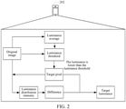
- the foregoing method for adjusting image luminance may be applied to a hardware environment formed by a terminal 202 shown in FIG. 2 .
- the terminal 202 determines a target pixel with luminance lower than a luminance threshold in an original image, the luminance threshold being a threshold determined according to luminance of pixels in the original image; and obtains a luminance distribution intensity of pixels adjacent to the target pixel in the original image.
- the luminance distribution intensity of the adjacent pixels described herein may reflect luminance of the adjacent pixel of the target pixel.
- the luminance distribution intensity may be a luminance average of the plurality of adjacent pixels, to comprehensively reflect luminance of the adjacent pixels.
- the method for adjusting image luminance may be applied to, but not limited to, a scenario in which an image is displayed on a terminal.
- the terminal may include, but not limited to: a mobile phone, a tablet computer, a personal computer, a smart wearable device, a smart home device, and the like.
- the method for adjusting image luminance may be applied to, but not limited to, a client installed on the terminal.
- the client may be, but not limited to, various applications, for example, an on-line education application, an instant messaging application, a community space application, a game application, a shopping application, a browser application, a financial application, a multimedia application, and a live broadcast application.
- the method for adjusting image luminance may be applied to, but not limited to, a scenario in which an image is displayed in a multimedia application installed on the foregoing mobile phone, or may be applied to, but not limited to, a scenario in which an image is displayed in an instant messaging application installed on the foregoing smart wearable device, to improve an adjustment effect when luminance adjustment is performed on the image.
- the foregoing description is merely an example, which is not limited in this embodiment.
- the foregoing method for adjusting image luminance may be further applied to a server.
- the server may be configured to provide a luminance adjustment service for the terminal. By performing the method, the server may determine the target luminance for luminance adjustment of the target pixel, and transmit the target luminance to the terminal, so that the terminal performs luminance adjustment on the target pixel according to the target luminance.
- the server may be an independent server, or may be a server in a cluster or a cloud server.
- the adjacent pixel adjacent to the target pixel may be, but not limited to, a pixel within a predetermined range around the target pixel.
- the predetermined range may be, but not limited to, a distance value, and pixels with distances from the target pixel being less than the distance value are all determined to be adjacent pixels adjacent to the target pixel.
- the adjacent pixel adjacent to the target pixel may be, but not limited to, a point located in a predetermined direction of the target pixel.
- adjacent pixels adjacent to the target pixel are eight points located above, below, left, right, top left, bottom left, top right, and bottom right of the target pixel.
- the luminance threshold is determined according to the luminance of the pixels in the original image.
- the luminance threshold may be determined according to an average of the luminance of the pixels in the original image. If a luminance average of the pixels in the original image is relatively high, the image itself may be relatively bright, and then a relatively high luminance threshold may be determined. If a luminance average of the pixels in the original image is relatively low, the image itself may be relatively dark, and then a relatively low luminance threshold may be determined.
- luminance adjustment is more flexible and more consistent with true contrast of the original image.
- determining the difference between the luminance threshold and the luminance distribution intensity of the adjacent pixels in S106 described above may include: determining the difference between the luminance threshold and the luminance distribution intensity of the adjacent pixels when the luminance distribution intensity is lower than the luminance threshold. That is, when it is determined that the luminance of the adjacent pixel of the target pixel is relatively low, the difference between the luminance threshold and the luminance distribution intensity of the adjacent pixels may be determined, to perform luminance adjustment on the target pixel.
- the luminance adjustment may not be performed on the target pixel, to reserve pixel contrast of the original image at the target pixel.
- the terminal may cancel luminance adjustment of the target pixel when the luminance distribution intensity is higher than the luminance threshold.
- luminance adjustment is performed on the target pixel when the luminance of the adjacent pixel is relatively low, and luminance adjustment of the target pixel is canceled when the luminance of the adjacent pixel is relatively high, which can effectively reduce the quantity of pixels for the luminance adjustment, and improve the efficiency of luminance adjustment of the image.
- an original image that needs to be displayed on the terminal is image A, where a luminance average of pixels in image A is P.
- a luminance threshold determined by the terminal according to the luminance average P is M.
- the terminal determines that target pixels with luminance lower than M in image A are a point B and a point C.
- the terminal obtains a luminance distribution intensity N of pixels adjacent to the point B and a luminance distribution intensity Q of pixels adjacent to the point C in image A.
- a difference between M and N is determined, namely M - N, and it is determined that a target luminance adjustment curve corresponding to M - N is S1.
- Original luminance L of the point B is then adjusted to target luminance L' shown on the target luminance adjustment curve according to the target luminance adjustment curve S1.
- luminance distribution intensity Q corresponding to the point C is higher than M, luminance adjustment of the point C is canceled.
- adjusting the target pixel to the corresponding target luminance according to the difference and the original luminance of the target pixel in S108 described above may include: determining a target luminance adjustment curve corresponding to the difference.
- the target luminance adjustment curve may reflect the target luminance that needs to be adjusted to for the target pixel according to relative luminance changes of different target pixels and luminance distribution intensities of adjacent pixels.
- the original luminance of the target pixel is then adjusted to the target luminance shown on the target luminance adjustment curve according to the target luminance adjustment curve.
- the luminance threshold is determined according to the luminance of the pixels in the original image
- the target pixel with luminance lower than the luminance threshold is determined in the original image
- the original luminance of the target pixel is adjusted based on the difference between the luminance threshold and the luminance distribution intensity.
- the luminance threshold is dynamically determined according to the luminance of the pixels in the original image
- the luminance threshold is more consistent with luminance distribution of the pixels in the original image.
- luminance of adjacent pixels can be taken into account for the luminance adjustment of the target pixel, and a changing characteristic of relative luminance between the target pixel and the adjacent pixel is reserved.
- the luminance adjustment is more consistent with the luminance distribution of the original image, thereby achieving the technical effect of improving an adjustment effect of luminance adjustment on an image.
- the determining a target luminance adjustment curve corresponding to the difference includes:
- the adjustment intensity may reflect the intensity of luminance adjustment of the target pixel. The greater the adjustment intensity is, the higher the target luminance after adjustment of the target pixel is; and the smaller the adjustment intensity is, the lower the target luminance after the adjustment of the target pixel is.
- a plurality of luminance adjustment curves may be preset, to thereby determine, according to the adjustment intensity determined by using the difference and the luminance average of the pixels in the original image, a luminance adjustment curve corresponding to the luminance threshold from the luminance adjustment curves as the target luminance adjustment curve.
- the basis for luminance adjustment may be achieved by a relationship between a luminance distribution intensity of adjacent pixels around the pixel and the luminance threshold.
- S represents an adjustment intensity of the luminance of the target pixel.
- the basis thereof is that when the luminance distribution intensity of the adjacent pixels around the target pixel is much lower than a luminance threshold T, the luminance of the pixel needs to be enhanced considerably.
- the luminance distribution intensity of the adjacent pixel around the target pixel is slightly lower than the luminance threshold T, the luminance of the pixel only needs to be slightly enhanced. In this way, it is ensured that when the pixel falls in a large dark area, luminance of the dark area will be all greatly enhanced. Conversely, when the pixel falls in a small dark area but luminance of adjacent pixels is too high, the dark area will only be slightly enhanced to ensure uniqueness of the dark area.
- an adjusted luminance intensity converges between a luminance value 0 and the luminance threshold T according to the foregoing situational result.
- a curvature of the target luminance adjustment curve is adjusted according to the foregoing adjustment intensity S. For example, an original luminance value is 0.15, and this luminance will be enhanced to different target luminance (0.165, 0.185, 0.215) by different adjustment intensities S (1.0, 2.0, 3.0).
- the foregoing luminance adjustment formula does not need a large number of time-consuming mathematical operation functions, and the entire mathematical operation logic is very suitable for directly running on a graphics processing unit (GPU) pipeline (by using a shader).
- GPU graphics processing unit
- This may not only be connected with a Mipmap function, but also ensure that overall operating costs are minimized.
- Requirements for computing efficiency and memory usage of the device are relatively low, so that a high-quality dark part adjustment and rendering mechanism can be achieved on a smartphone with poor requirements for computing efficiency and memory usage.
- the method before the determining a target pixel with luminance lower than a luminance threshold in an original image, the method further includes:
- the luminance average of the entire image needs to be taken into account, to dynamically generate the luminance threshold, and the threshold is used to measure which pixels in the image need luminance adjustment.
- a luminance distribution intensity of a neighboring pixel of the pixel that is, an adjacent pixel, needs to be calculated first, and an intensity of luminance adjustment required is determined by using the luminance distribution intensity.
- the pixels of the entire image need to be polled first, to calculate the luminance average.
- the entire image needs to be polled again to compare the luminance of the pixels with the luminance threshold, to further determine pixels whose luminance needs to be adjusted.
- luminance of the pixel when the luminance of the pixel is adjusted, luminance of neighboring pixels of the pixel, that is, the adjacent pixels, needs to be polled to calculate the adjacent luminance distribution intensity as the basis for later luminance adjustment of the pixel.
- the various calculations are excessively time-consuming, and can hardly meet the requirements of adjusting in a real time manner luminance of a dark part in an image with a large screen resolution.
- current smartphones are all equipped with a high-performance GPU graphics pipeline architecture.
- the GPU graphics pipelines are all formulated following the same standard (OpenGL ES). Therefore, if the calculation of the luminance average and the adjacent luminance distribution intensity is implemented by using the GPU graphics pipeline, not only can the calculation time required be greatly reduced, but also it can be ensured that this method can run on most smartphones.
- the luminance average and the luminance distribution intensity of the neighboring pixel that is, the adjacent pixel
- the GPU graphics pipeline for example, by writing a Compute Shader program for the calculation, or by a plurality of times of texture dimensionality reduction rendering.
- the luminance average and the luminance distribution intensity may be determined by using the Mipmap function of the GPU graphics pipeline.
- the determining the luminance average of the pixels in the original image by using a Mipmap function of a GPU graphics pipeline includes:
- the GPU when a Mipmap generation instruction is issued to the GPU graphics pipeline, the GPU respectively generates images with resolutions lower than that of the original image in a power-of-two attenuation manner, and the luminance of the first image with the resolution of 1 ⁇ 1 is determined as the luminance average of the pixels in the original image.
- a leftmost original image is an original image with a 128 ⁇ 128 resolution.
- the GPU respectively generates reduced images with different resolutions such as 64 ⁇ 64, 32 ⁇ 32, 16 ⁇ 16, 8 ⁇ 8, 4 ⁇ 4, 2 ⁇ 2, and 1 ⁇ 1 which attenuate exponentially by power of 1/2.
- a color of each pixel in a small image at each scale is of a color value generated by averaging colors of four pixels in a corresponding position of a large image at a previous scale. In other words, a small image at each scale may be regarded as a result of color averaging of a large image at a previous scale.
- a color value of a pixel in the image with a 1 ⁇ 1 resolution may be regarded as a color value obtained by averaging colors of all pixels in the original image with a 128 ⁇ 128 resolution. Because the Mipmap function is directly generated by hardware in the GPU graphics pipeline, generation efficiency thereof is very good, and may be regarded as a powerful tool with almost no additional computing cost.
- a pixel luminance value of the 1 ⁇ 1 image may be used as the luminance threshold for determining a dark part whose luminance needs to be adjusted subsequently.
- the obtaining a luminance distribution intensity of pixels adjacent to the target pixel in the original image includes:
- the Mipmap function may be used to accelerate the process of calculating the luminance distribution intensity of the adjacent pixels.
- a middle-scale low resolution (for example: 64 ⁇ 64) of a Mipmap is used as a reference
- a color luminance value of each pixel in an image with the resolution of 64 ⁇ 64 may be regarded as a color luminance average of a block (image width divided by 64 and image height divided by 64) in the original image.
- the same image coordinate position in the image with the 64 ⁇ 64 resolution may be directly queried, for example, a coordinate position of a target pixel in the original image is (0.3, 0.5), and luminance of a corresponding pixel at the image coordinate position (0.3, 0.5) in the image with the 64 ⁇ 64 resolution may be queried.
- average luminance data representing a color of the block (image width divided by 64 and image height divided by 64) neighboring the pixel in the original image is returned.
- the average luminance data may be used as the luminance distribution intensity of the neighboring pixel, that is, the adjacent pixel, which serves as the basis for adjusting the luminance of the pixel.
- the method according to the foregoing embodiment may be implemented by software plus a necessary universal hardware platform, or by using hardware, but in many cases, the former is a preferred implementation.
- the technical solutions of this application essentially or the part contributing to the related art may be implemented in the form of a software product.
- the computer software product is stored in a storage medium (such as a read-only memory (ROM)/random access memory (RAM), a magnetic disk, or an optical disc), and includes several instructions for instructing a terminal device (which may be a mobile phone, a computer, a server, a network device, or the like) to perform the method described in the embodiments of this application.
- an apparatus for adjusting image luminance configured to implement the foregoing method for adjusting image luminance is further provided. As shown in FIG. 7a , the apparatus includes:
- the apparatus further includes:
- the second determining module is configured to: determine the difference between the luminance threshold and the luminance distribution intensity of the adjacent pixels when the luminance distribution intensity is lower than the luminance threshold.
- the adjacent pixel adjacent to the target pixel may be, but not limited to, a pixel within a predetermined range around the target pixel.
- the predetermined range may be, but not limited to, a distance value, and pixels with distances from the target pixel less than the distance value are all determined to be adjacent pixels adjacent to the target pixel.
- the adjacent pixel adjacent to the target pixel may be, but not limited to, a point located in a predetermined direction of the target pixel.
- adjacent pixels adjacent to the target pixel are eight points located above, below, left, right, top left, bottom left, top right, and bottom right of the target pixel.
- the luminance threshold is determined according to the luminance of the pixels in the original image.
- the luminance threshold may be determined according to an average of the luminance of the pixels in the original image. For example, if a luminance average of the pixels in the original image is relatively high, the image itself may be relatively bright, and then a relatively high luminance threshold may be determined. If a luminance average of the pixels in the original image is relatively low, the image itself may be relatively dark, and then a relatively low luminance threshold may be determined.
- luminance adjustment is more flexible and more consistent with true contrast of the original image.
- the luminance threshold is determined according to the luminance of the pixels in the original image, the target pixel with luminance lower than the luminance threshold is determined in the original image, and the original luminance of the target pixel is adjusted based on the difference between the luminance threshold and the luminance distribution intensity. Because the luminance threshold is dynamically determined according to the luminance of the pixels in the original image, the luminance threshold is more consistent with luminance distribution of the pixels in the original image. Through dynamic luminance adjustment based on the difference between the luminance threshold and the luminance distribution intensity, luminance of an adjacent pixel can be taken into account for the luminance adjustment of the target pixel, and a changing characteristic of relative luminance between the target pixel and the adjacent pixel is reserved. The luminance adjustment is more consistent with the luminance distribution of the original image, thereby achieving the technical effect of improving an adjustment effect of luminance adjustment on an image.
- FIG. 8 is a schematic diagram 2 of an apparatus for adjusting image luminance according to an embodiment of this application.
- the foregoing apparatus further includes: a cancellation module 802, configured to cancel luminance adjustment of the target pixel in response to that the luminance distribution intensity is higher than the luminance threshold.
- FIG. 9 is a schematic diagram 3 of an apparatus for adjusting image luminance according to an embodiment of this application.
- the third determining module 708 includes:
- a plurality of luminance adjustment curves may be preset, to thereby determine, according to the adjustment intensity determined by using the difference and the luminance average of the pixels in the original image, a luminance adjustment curve corresponding to the luminance threshold from the luminance adjustment curves as the target luminance adjustment curve.
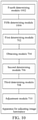
- FIG. 10 is a schematic diagram 4 of an apparatus for adjusting image luminance according to an embodiment of this application.
- the foregoing apparatus further includes:
- current smartphones are all equipped with a high-performance GPU graphics pipeline architecture.
- the GPU graphics pipelines are all formulated following the same standard (OpenGL ES). Therefore, if the calculation of the luminance average and the adjacent luminance distribution intensity is implemented by using the GPU graphics pipeline, not only can the calculation time required be greatly reduced, but also it can be ensured that this method can run on most smartphones.
- the luminance average and the luminance distribution intensity may be determined by using the Mipmap function of the GPU graphics pipeline.
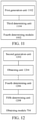
- FIG. 11 is a schematic diagram 5 of an apparatus for adjusting image luminance according to an embodiment of this application.
- the fourth determining module 1002 includes:
- the GPU when a Mipmap generation instruction is issued to the GPU graphics pipeline, the GPU respectively generates images with resolutions lower than that of the original image in a power-of-two attenuation manner, and the luminance of the first image with the resolution of 1 ⁇ 1 is determined as the luminance average of the pixels in the original image.
- FIG. 12 is a schematic diagram 6 of an apparatus for adjusting image luminance according to an embodiment of this application.
- the obtaining module 704 includes:
- the Mipmap function may be used to accelerate the process of calculating the luminance distribution intensity of the adjacent pixels.
- a middle-scale low resolution (for example: 64 ⁇ 64) of a Mipmap is used as a reference
- a color luminance value of each pixel in an image with the resolution of 64 ⁇ 64 may be regarded as a color luminance average of a block (image width divided by 64 and image height divided by 64) in the original image.
- the application environment of this embodiment of this application may be but is not limited to the application environment of the foregoing embodiment, which is not described in detail in this embodiment.
- An embodiment of this application provides an optional specific application example for implementing the foregoing connection method of real-time communication.
- the foregoing method for adjusting image luminance may be applied to, but not limited to, a scenario in which an image is displayed on a terminal as shown in FIG. 13 .
- a system for adjusting image luminance is provided.
- the system includes the following modules.
- a luminance propagation map generator module the meaning of luminance propagation map is to record a luminance distribution intensity of another pixel around a pixel in an image, which is used to determine a curvature of a target luminance adjustment curve when luminance of the pixel needs to be enhanced.
- the image may be directly represented by a small image at a scale with a low resolution in the Mipmap.
- luminance average map is an average luminance of an entire picture.
- the image may be directly represented by a small image with the lowest resolution 1 ⁇ 1 in the Mipmap.
- a function of the luminance propagation map generator module is mainly to generate a luminance propagation map and a luminance average map.
- the function of the entire module can be obtained only by calling the Mipmap function of the GPU graphics pipeline, and then selecting a small image at a scale of a relatively low resolution and the small image with the 1 ⁇ 1 resolution. Because the entire module uses the Mipmap function, computing costs required overall are minimized.
- a dark-threshold generator module the dark-threshold is a luminance threshold, and is used to determine whether a pixel in an image needs luminance optimization adjustment. Because the luminance threshold is based on a luminance average of the entire image, the result of the image with the 1 ⁇ 1 resolution in the Mipmap generated by the luminance propagation map generator in the previous step may be directly used to obtain the luminance threshold without any additional computing cost.
- a luminance curve adjustor module a curve generator module configured to adjust luminance of a pixel.
- the module is mainly configured to generate, according to a difference between a luminance distribution intensity around a pixel and a luminance threshold, a target luminance adjustment curve consistent with a curvature of the difference, and determine target luminance through the curve.
- a mathematical formula of the curve generator is a combination of extremely low-cost mathematical expressions as shown previously.
- the curve generation process may be integrated into the fragment shader in the GPU graphics pipeline together with the subsequent processing of whether to perform pixel optimization adjustment.
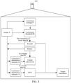
- the luminance propagation map module generates, from the original image and by using the Mipmap function, a luminance propagation map representing a luminance distribution intensity around each pixel and an overall luminance average map with a 1 ⁇ 1 resolution.
- Each pixel in the image runs the fragment shader in the GPU graphics pipeline, where a luminance average of the entire image is obtained from the luminance average map with a 1 ⁇ 1 resolution, and a luminance threshold is generated by the dark-threshold generator.
- the luminance distribution intensity around each pixel in the image is obtained by querying the luminance propagation map.
- the luminance distribution intensity around the pixel is compared with the luminance threshold. If the luminance distribution intensity around the pixel is higher than the luminance threshold, no luminance optimization adjustment is performed. If the luminance distribution intensity around the pixel is lower than the luminance threshold, a difference between the luminance distribution intensity around the pixel and the luminance threshold is calculated.
- a query curve matching the difference is obtained by the luminance curve adjustor with the luminance difference. Then the curve is used to determine and adjust the target luminance of the pixel.
- an electronic device configured to perform the foregoing method for adjusting image luminance.
- the electronic device includes: one or more (only one is shown in the figure) processors 1502, a memory 1504, a sensor 1506, an encoder 1508, and a transmission apparatus 1510.
- the memory stores a computer program
- the processor is configured to perform, by using the computer program, the steps in any one of the foregoing method embodiments.
- the electronic device may be located in at least one of a plurality of network electronic devices of a computer network.
- the processor may be configured to perform the following steps by using the computer program:
- the electronic device may be alternatively a terminal device such as a smartphone (for example, an Android mobile phone or an iOS mobile phone), a tablet computer, a palmtop computer, a mobile Internet device (MID), or a PAD.
- a terminal device such as a smartphone (for example, an Android mobile phone or an iOS mobile phone), a tablet computer, a palmtop computer, a mobile Internet device (MID), or a PAD.
- FIG. 15 does not constitute a limitation on a structure of the foregoing electronic device.
- the electronic device may alternatively include more (such as a network interface and a display device) or fewer components than those shown in FIG. 15 , or has a configuration different from that shown in FIG. 15 .
- the memory 1504 may be configured to store a software program and modules, for example, program instructions/modules corresponding to the method and apparatus for adjusting image luminance in the embodiments of this application.
- the processor 1502 runs the software program and modules stored in the memory 1504, to perform various functional application and data processing, that is, implement the foregoing target component control method.
- the memory 1504 may include a high-speed random access memory, and may also include a non-volatile memory, for example, one or more magnetic storage apparatuses, a flash memory, or another non-volatile solid-state memory.
- the memory 1504 may further include memories remotely disposed relative to the processor 1502, and the remote memories may be connected to a terminal by using a network. Examples of the network include, but not limited to, the Internet, an intranet, a local area network, a mobile communication network, and a combination thereof.
- the transmission apparatus 1510 is configured to receive or transmit data by using a network.
- Specific examples of the foregoing network may include a wired network and a wireless network.
- the transmission apparatus 1510 includes a network interface controller (NIC), which may be connected to another network device and a router by using a network cable, to communicate with the Internet or a local area network.
- the transmission apparatus 1510 is a radio frequency (RF) module, which communicates with the Internet in a wireless manner.
- NIC network interface controller
- RF radio frequency
- the memory 1504 is configured to store an application.
- An embodiment of this application further provides a storage medium, storing a computer program, the computer program being used for performing the steps in any one of the foregoing method embodiments when being run.
- the storage medium may be configured to store a computer program for performing the following steps:
- the storage medium is further configured to store a computer program used for performing the steps included in the methods according to the foregoing embodiments, and details are not described again in this embodiment.
- a person of ordinary skill in the art may understand that all or some of the steps of the methods in the foregoing embodiments may be implemented by a program instructing relevant hardware of the terminal device.
- the program may be stored in a computer-readable storage medium, and the storage medium may include a flash disk, a read-only memory (ROM), a random access memory (RAM), a magnetic disk, an optical disc, or the like.
- An embodiment of this application further provides a computer program product including instructions, the computer program product, when run on a computer, causing the computer to perform the method according to any one of the foregoing embodiments.
- the integrated unit in the foregoing embodiments When the integrated unit in the foregoing embodiments is implemented in a form of a software functional unit and sold or used as an independent product, it may be stored in the foregoing computer-readable storage medium.
- the computer software product is stored in a storage medium and includes several instructions for instructing one or more computer devices (which may be a personal computer, a server, a network device, and the like) to perform all or some of the steps of the methods described in the embodiments of this application.
- the disclosed client may be implemented in another manner.
- the apparatus embodiments described above are merely exemplary.
- the unit division is merely logical function division and may be other division in actual implementation.
- a plurality of units or components may be combined or integrated into another system, or some features may be ignored or not performed.
- the displayed or discussed mutual couplings or direct couplings or communication connections may be implemented through some interfaces.
- the indirect couplings or communication connections between the units or modules may be implemented in electrical or other forms.
- the units described as separate components may or may not be physically separated, and the components displayed as units may or may not be physical units, and may be located in one place or may be distributed on a plurality of network units. Some or all of the units may be selected according to actual requirements to achieve the objectives of the solutions of the embodiments.
- functional units in the embodiments of this application may be integrated into one processing unit, or each of the units may exist alone physically, or two or more units may be integrated into one unit.
- the integrated unit may be implemented in a form of hardware, or may be implemented in a form of a software functional unit.
Landscapes
- Engineering & Computer Science (AREA)
- Physics & Mathematics (AREA)
- General Physics & Mathematics (AREA)
- Theoretical Computer Science (AREA)
- Computer Hardware Design (AREA)
- Image Processing (AREA)
- Controls And Circuits For Display Device (AREA)
- Transforming Electric Information Into Light Information (AREA)
- Picture Signal Circuits (AREA)
Applications Claiming Priority (2)
| Application Number | Priority Date | Filing Date | Title |
|---|---|---|---|
| CN201910368934.3A CN110120021B (zh) | 2019-05-05 | 2019-05-05 | 图像亮度的调整方法、装置、存储介质及电子装置 |
| PCT/CN2020/084581 WO2020224390A1 (fr) | 2019-05-05 | 2020-04-14 | Procédé et dispositif de réglage de luminosité d'image, support de stockage et dispositif électronique |
Publications (2)
| Publication Number | Publication Date |
|---|---|
| EP3968268A1 true EP3968268A1 (fr) | 2022-03-16 |
| EP3968268A4 EP3968268A4 (fr) | 2022-07-13 |
Family
ID=67520359
Family Applications (1)
| Application Number | Title | Priority Date | Filing Date |
|---|---|---|---|
| EP20801932.3A Pending EP3968268A4 (fr) | 2019-05-05 | 2020-04-14 | Procédé et dispositif de réglage de luminosité d'image, support de stockage et dispositif électronique |
Country Status (7)
| Country | Link |
|---|---|
| US (2) | US11587530B2 (fr) |
| EP (1) | EP3968268A4 (fr) |
| JP (1) | JP7226893B2 (fr) |
| KR (1) | KR102548745B1 (fr) |
| CN (1) | CN110120021B (fr) |
| SG (1) | SG11202105754RA (fr) |
| WO (1) | WO2020224390A1 (fr) |
Families Citing this family (15)
| Publication number | Priority date | Publication date | Assignee | Title |
|---|---|---|---|---|
| CN110120021B (zh) | 2019-05-05 | 2021-04-09 | 腾讯科技(深圳)有限公司 | 图像亮度的调整方法、装置、存储介质及电子装置 |
| CN110766703A (zh) * | 2019-10-21 | 2020-02-07 | 合肥成方信息技术有限公司 | 基于GPU的Compute Shader的智能图像识别方法 |
| CN110910333B (zh) * | 2019-12-12 | 2023-03-14 | 腾讯科技(深圳)有限公司 | 图像处理方法和图像处理设备 |
| CN112750086B (zh) * | 2020-08-31 | 2024-10-15 | 腾讯科技(深圳)有限公司 | 一种图像处理方法、装置、电子设备及存储介质 |
| CN112669227B (zh) * | 2020-12-16 | 2023-10-17 | Tcl华星光电技术有限公司 | 图标边缘处理方法、装置和计算机可读存储介质 |
| US20240062530A1 (en) * | 2020-12-17 | 2024-02-22 | Trustees Of Tufts College | Deep perceptual image enhancement |
| CN112383719B (zh) * | 2021-01-13 | 2022-02-01 | 腾讯科技(深圳)有限公司 | 图像亮度的调整方法、装置、设备及可读存储介质 |
| CN113920239B (zh) * | 2021-10-09 | 2026-02-27 | 网易(杭州)网络有限公司 | 贴图亮度的调整方法、装置、设备及存储介质 |
| CN114387186A (zh) * | 2022-01-12 | 2022-04-22 | Tcl通讯科技(成都)有限公司 | 可见度调整方法、装置、电子设备和计算机可读存储介质 |
| US20230317023A1 (en) * | 2022-04-05 | 2023-10-05 | Meta Platforms Technologies, Llc | Local dimming for artificial reality systems |
| CN117392244A (zh) * | 2022-06-30 | 2024-01-12 | 宜宾市极米光电有限公司 | 图像处理方法、装置、电子设备和存储介质 |
| CN115578291B (zh) * | 2022-11-01 | 2026-04-03 | 深圳理工大学 | 图像的亮度校正方法、存储介质及电子设备 |
| CN116366985B (zh) * | 2023-02-23 | 2025-09-30 | 深圳因赛德思医疗科技有限公司 | 图像测光曝光处理方法、系统、终端设备以及存储介质 |
| US12288531B2 (en) | 2023-04-17 | 2025-04-29 | Meta Platforms Technologies, Llc | Systems and methods for performing global dimming in artificial reality systems |
| US20240062436A1 (en) * | 2023-10-09 | 2024-02-22 | Sony Interactive Entertainment LLC | Using stable diffusion to produce images conforming to color palette |
Family Cites Families (44)
| Publication number | Priority date | Publication date | Assignee | Title |
|---|---|---|---|---|
| KR101089394B1 (ko) * | 2003-09-11 | 2011-12-07 | 파나소닉 주식회사 | 시각 처리 장치, 시각 처리 방법, 시각 처리 프로그램 및 반도체 장치 |
| JP4414307B2 (ja) * | 2003-09-11 | 2010-02-10 | パナソニック株式会社 | 視覚処理装置、視覚処理方法、視覚処理プログラムおよび半導体装置 |
| KR100590529B1 (ko) * | 2003-11-04 | 2006-06-15 | 삼성전자주식회사 | 영상의 국부적 휘도 향상 방법 및 장치와 컴퓨터프로그램을 저장하는 컴퓨터로 읽을 수 있는 기록 매체 |
| TWI292138B (en) * | 2004-03-11 | 2008-01-01 | Mstar Semiconductor Inc | Device for adaptively adjusting video's luminance and related method |
| JP4577621B2 (ja) * | 2004-09-01 | 2010-11-10 | 日本電気株式会社 | 画像補正処理システム及び画像補正処理方法 |
| JP4683994B2 (ja) * | 2005-04-28 | 2011-05-18 | オリンパス株式会社 | 画像処理装置、画像処理方法、電子カメラ、スキャナ |
| JP4440245B2 (ja) * | 2005-10-12 | 2010-03-24 | パナソニック株式会社 | 視覚処理装置、表示装置および集積回路 |
| JP4094652B2 (ja) * | 2006-04-28 | 2008-06-04 | 松下電器産業株式会社 | 視覚処理装置、視覚処理方法、プログラム、記録媒体、表示装置および集積回路 |
| KR100809347B1 (ko) * | 2006-07-31 | 2008-03-05 | 삼성전자주식회사 | 쉐도우 영역 보상 방법 및 장치 |
| JP5004717B2 (ja) * | 2006-08-28 | 2012-08-22 | パナソニック株式会社 | 描画装置、描画方法、および描画プログラム |
| JP4221434B2 (ja) * | 2006-10-04 | 2009-02-12 | 株式会社ナナオ | 輪郭補正方法、画像処理装置及び表示装置 |
| KR100977396B1 (ko) * | 2008-08-08 | 2010-08-24 | 팅크웨어(주) | 밉맵 이미지 처리 장치 및 그 방법 |
| TWI464706B (zh) * | 2009-03-13 | 2014-12-11 | Micro Star Int Co Ltd | 以單張影像模擬高動態範圍之暗部曝光補償方法及其應用該方法的影像處理裝置 |
| WO2010116522A1 (fr) * | 2009-04-10 | 2010-10-14 | パイオニア株式会社 | Dispositif, procédé et programme de traitement d'image et support de stockage sur lequel ledit programme est enregistré, et dispositif d'affichage |
| JP4803284B2 (ja) * | 2009-07-08 | 2011-10-26 | カシオ計算機株式会社 | 画像処理装置、及び画像処理プログラム |
| JP5495025B2 (ja) * | 2009-12-22 | 2014-05-21 | ソニー株式会社 | 画像処理装置および方法、並びにプログラム |
| JP5410378B2 (ja) * | 2010-07-21 | 2014-02-05 | 日本放送協会 | 映像信号補正装置および映像信号補正プログラム |
| US8559059B2 (en) * | 2010-07-29 | 2013-10-15 | Brother Kogyo Kabushiki Kaisha | Image processing device superimposing supplemental image to encompass area of original based on luminance difference between nearby pixels |
| US9105078B2 (en) * | 2012-05-31 | 2015-08-11 | Apple Inc. | Systems and methods for local tone mapping |
| KR101981573B1 (ko) * | 2012-11-22 | 2019-05-23 | 삼성전자주식회사 | 이미지 신호 프로세서 및 이미지 신호 프로세서를 포함하는 모바일 촬영 장치 |
| CN103971330B (zh) * | 2013-02-05 | 2017-10-20 | 腾讯科技(深圳)有限公司 | 图像增强方法及装置 |
| TWI536341B (zh) * | 2014-03-21 | 2016-06-01 | 緯創資通股份有限公司 | 顯示補償方法與顯示補償系統 |
| JP6042030B2 (ja) | 2014-03-28 | 2016-12-14 | 富士フイルム株式会社 | 画像処理装置、撮影装置、画像処理方法、及びプログラム |
| JP2015197473A (ja) * | 2014-03-31 | 2015-11-09 | ソニー株式会社 | 信号処理方法、表示装置、及び電子機器 |
| CN104301624B (zh) * | 2014-10-30 | 2018-04-03 | 青岛海信移动通信技术股份有限公司 | 一种图像拍摄亮度控制方法及装置 |
| CN104517268B (zh) * | 2014-12-24 | 2017-09-26 | 小米科技有限责任公司 | 调整图像亮度的方法及装置 |
| CN104715735B (zh) * | 2015-03-31 | 2017-08-25 | 福州瑞芯微电子股份有限公司 | 一种背光调整的方法和装置 |
| WO2016165967A1 (fr) * | 2015-04-14 | 2016-10-20 | Fotonation Limited | Procédé et appareil d'acquisition d'images |
| US10140953B2 (en) * | 2015-10-22 | 2018-11-27 | Dolby Laboratories Licensing Corporation | Ambient-light-corrected display management for high dynamic range images |
| US20170178395A1 (en) * | 2015-12-16 | 2017-06-22 | Google Inc. | Light field rendering of an image using variable computational complexity |
| JP6834383B2 (ja) * | 2016-11-14 | 2021-02-24 | ブラザー工業株式会社 | 画像読取装置及び決定方法 |
| CN109145678B (zh) * | 2017-06-15 | 2020-12-11 | 杭州海康威视数字技术股份有限公司 | 信号灯检测方法及装置和计算机设备及可读存储介质 |
| CN107545871B (zh) * | 2017-09-30 | 2020-03-24 | 青岛海信电器股份有限公司 | 图像亮度处理方法及装置 |
| CN108307125B (zh) * | 2018-02-08 | 2021-10-08 | 腾讯科技(深圳)有限公司 | 一种图像采集方法、装置和存储介质 |
| CN108806616A (zh) * | 2018-05-30 | 2018-11-13 | 深圳市零度智控科技有限公司 | 背光控制方法、装置及计算机可读存储介质 |
| CN108924525B (zh) * | 2018-06-06 | 2021-07-06 | 平安科技(深圳)有限公司 | 图像亮度调整方法、装置、计算机设备及存储介质 |
| CN109064998A (zh) * | 2018-06-28 | 2018-12-21 | 努比亚技术有限公司 | 一种屏幕亮度调节方法、终端及计算机可读存储介质 |
| CN109064431B (zh) * | 2018-08-23 | 2021-10-26 | 腾讯数码(天津)有限公司 | 一种图片亮度调节方法、设备及其存储介质 |
| CN109587392B (zh) * | 2018-10-18 | 2020-12-22 | 蒋涛 | 监控设备的调整方法及装置、存储介质、电子装置 |
| CN109256077B (zh) * | 2018-11-01 | 2021-12-14 | 京东方科技集团股份有限公司 | 显示面板的控制方法、装置及可读存储介质 |
| CN109686342B (zh) * | 2018-12-25 | 2021-04-06 | 海信视像科技股份有限公司 | 一种图像处理方法及装置 |
| CN109697738B (zh) * | 2018-12-28 | 2024-09-10 | Oppo广东移动通信有限公司 | 图像处理方法、装置、终端设备及存储介质 |
| CN109672829B (zh) * | 2019-01-04 | 2021-02-02 | Oppo广东移动通信有限公司 | 图像亮度的调整方法、装置、存储介质及终端 |
| CN110120021B (zh) * | 2019-05-05 | 2021-04-09 | 腾讯科技(深圳)有限公司 | 图像亮度的调整方法、装置、存储介质及电子装置 |
-
2019
- 2019-05-05 CN CN201910368934.3A patent/CN110120021B/zh active Active
-
2020
- 2020-04-14 JP JP2021547520A patent/JP7226893B2/ja active Active
- 2020-04-14 EP EP20801932.3A patent/EP3968268A4/fr active Pending
- 2020-04-14 WO PCT/CN2020/084581 patent/WO2020224390A1/fr not_active Ceased
- 2020-04-14 SG SG11202105754RA patent/SG11202105754RA/en unknown
- 2020-04-14 KR KR1020217021752A patent/KR102548745B1/ko active Active
-
2021
- 2021-06-09 US US17/343,544 patent/US11587530B2/en active Active
-
2023
- 2023-01-24 US US18/101,007 patent/US12062350B2/en active Active
Also Published As
| Publication number | Publication date |
|---|---|
| CN110120021B (zh) | 2021-04-09 |
| US11587530B2 (en) | 2023-02-21 |
| US20210295801A1 (en) | 2021-09-23 |
| US20230169935A1 (en) | 2023-06-01 |
| CN110120021A (zh) | 2019-08-13 |
| KR102548745B1 (ko) | 2023-06-27 |
| SG11202105754RA (en) | 2021-06-29 |
| JP2022520264A (ja) | 2022-03-29 |
| EP3968268A4 (fr) | 2022-07-13 |
| WO2020224390A1 (fr) | 2020-11-12 |
| KR20210102382A (ko) | 2021-08-19 |
| US12062350B2 (en) | 2024-08-13 |
| JP7226893B2 (ja) | 2023-02-21 |
Similar Documents
| Publication | Publication Date | Title |
|---|---|---|
| US12062350B2 (en) | Method and apparatus for adjusting image luminance, storage medium, and electronic device | |
| US11600040B2 (en) | Illumination rendering method and apparatus, storage medium, and electronic device | |
| CN110990510B (zh) | 三维地图生成方法、终端及服务器 | |
| CN110211218B (zh) | 画面渲染方法和装置、存储介质及电子装置 | |
| CN111897639A (zh) | 图像增广方法、装置、计算机设备及存储介质 | |
| CN113643414B (zh) | 一种三维图像生成方法、装置、电子设备及存储介质 | |
| CN111476851A (zh) | 图像处理方法、装置、电子设备及存储介质 | |
| CN102096945B (zh) | 空间数据渐进传输方法及装置 | |
| CN115984449A (zh) | 一种光照渲染方法、装置、电子设备及存储介质 | |
| US12367564B2 (en) | Image processing method, device, and medium | |
| US8390623B1 (en) | Proxy based approach for generation of level of detail | |
| CN104520831A (zh) | 用于平台和图像设备之间的通信的协议 | |
| CN114170068B (zh) | 图像特效的生成方法、装置、电子设备及存储介质 | |
| KR101582578B1 (ko) | 그래픽 처리 장치 및 방법 | |
| CN115049711B (zh) | 图像配准方法、装置、电子设备及介质 | |
| CN114820348B (zh) | 一种图像处理方法、装置、电子设备及存储介质 | |
| CN102682083B (zh) | 空间数据处理、化简与渐进传输的方法与装置 | |
| EP2586191A2 (fr) | Techniques pour transfert de couleur robuste | |
| Chang et al. | LSIM: Ultra lightweight similarity measurement for mobile graphics applications | |
| CN111462008A (zh) | 低照度图像增强方法、低照度图像增强装置和电子设备 | |
| CN116962656A (zh) | 色域转换方法、装置及电子设备 | |
| EP4550798A1 (fr) | Dispositif de transmission d'image et procédé de transmission d'image | |
| CN119494900A (zh) | 图像渲染方法和装置、存储介质及电子设备 | |
| CN117237249A (zh) | 一种无人机探测图像的透雾增强方法、装置以及电子设备 | |
| CN114820880A (zh) | 图像生成方法、装置及设备 |
Legal Events
| Date | Code | Title | Description |
|---|---|---|---|
| STAA | Information on the status of an ep patent application or granted ep patent |
Free format text: STATUS: THE INTERNATIONAL PUBLICATION HAS BEEN MADE |
|
| PUAI | Public reference made under article 153(3) epc to a published international application that has entered the european phase |
Free format text: ORIGINAL CODE: 0009012 |
|
| STAA | Information on the status of an ep patent application or granted ep patent |
Free format text: STATUS: REQUEST FOR EXAMINATION WAS MADE |
|
| 17P | Request for examination filed |
Effective date: 20210609 |
|
| AK | Designated contracting states |
Kind code of ref document: A1 Designated state(s): AL AT BE BG CH CY CZ DE DK EE ES FI FR GB GR HR HU IE IS IT LI LT LU LV MC MK MT NL NO PL PT RO RS SE SI SK SM TR |
|
| A4 | Supplementary search report drawn up and despatched |
Effective date: 20220614 |
|
| RIC1 | Information provided on ipc code assigned before grant |
Ipc: G09G 5/10 20060101ALI20220609BHEP Ipc: G06T 5/00 20060101AFI20220609BHEP |
|
| RAP3 | Party data changed (applicant data changed or rights of an application transferred) |
Owner name: TENCENT TECHNOLOGY (SHENZHEN) COMPANY LIMITED |
|
| DAV | Request for validation of the european patent (deleted) | ||
| DAX | Request for extension of the european patent (deleted) | ||
| STAA | Information on the status of an ep patent application or granted ep patent |
Free format text: STATUS: EXAMINATION IS IN PROGRESS |
|
| 17Q | First examination report despatched |
Effective date: 20240528 |