EP3968298B1 - Modélisation d'une situation - Google Patents
Modélisation d'une situation Download PDFInfo
- Publication number
- EP3968298B1 EP3968298B1 EP21195438.3A EP21195438A EP3968298B1 EP 3968298 B1 EP3968298 B1 EP 3968298B1 EP 21195438 A EP21195438 A EP 21195438A EP 3968298 B1 EP3968298 B1 EP 3968298B1
- Authority
- EP
- European Patent Office
- Prior art keywords
- data
- image sensor
- person
- movement
- image
- Prior art date
- Legal status (The legal status is an assumption and is not a legal conclusion. Google has not performed a legal analysis and makes no representation as to the accuracy of the status listed.)
- Active
Links
Images


Classifications
-
- B—PERFORMING OPERATIONS; TRANSPORTING
- B60—VEHICLES IN GENERAL
- B60W—CONJOINT CONTROL OF VEHICLE SUB-UNITS OF DIFFERENT TYPE OR DIFFERENT FUNCTION; CONTROL SYSTEMS SPECIALLY ADAPTED FOR HYBRID VEHICLES; ROAD VEHICLE DRIVE CONTROL SYSTEMS FOR PURPOSES NOT RELATED TO THE CONTROL OF A PARTICULAR SUB-UNIT
- B60W50/00—Details of control systems for road vehicle drive control not related to the control of a particular sub-unit, e.g. process diagnostic or vehicle driver interfaces
- B60W50/0097—Predicting future conditions
-
- G—PHYSICS
- G08—SIGNALLING
- G08B—SIGNALLING SYSTEMS, e.g. PERSONAL CALLING SYSTEMS; ORDER TELEGRAPHS; ALARM SYSTEMS
- G08B29/00—Checking or monitoring of signalling or alarm systems; Prevention or correction of operating errors, e.g. preventing unauthorised operation
- G08B29/12—Checking intermittently signalling or alarm systems
- G08B29/14—Checking intermittently signalling or alarm systems checking the detection circuits
-
- G—PHYSICS
- G06—COMPUTING OR CALCULATING; COUNTING
- G06V—IMAGE OR VIDEO RECOGNITION OR UNDERSTANDING
- G06V20/00—Scenes; Scene-specific elements
- G06V20/50—Context or environment of the image
- G06V20/52—Surveillance or monitoring of activities, e.g. for recognising suspicious objects
-
- G—PHYSICS
- G06—COMPUTING OR CALCULATING; COUNTING
- G06V—IMAGE OR VIDEO RECOGNITION OR UNDERSTANDING
- G06V40/00—Recognition of biometric, human-related or animal-related patterns in image or video data
- G06V40/20—Movements or behaviour, e.g. gesture recognition
- G06V40/23—Recognition of whole body movements, e.g. for sport training
-
- B—PERFORMING OPERATIONS; TRANSPORTING
- B60—VEHICLES IN GENERAL
- B60R—VEHICLES, VEHICLE FITTINGS, OR VEHICLE PARTS, NOT OTHERWISE PROVIDED FOR
- B60R1/00—Optical viewing arrangements; Real-time viewing arrangements for drivers or passengers using optical image capturing systems, e.g. cameras or video systems specially adapted for use in or on vehicles
Definitions
- a first image sensor has a first sensor effective range.
- the first image sensor creates first image sensor data from this first sensor effective range in a form comprising at least image data, which first image sensor data are forwarded to downstream units, such as an alarm unit, in a format known from the prior art or in an equally known form.
- the first image sensor can comprise a unit for converting the first image sensor data into a format suitable for processing in the alarm unit or a corresponding form, which also represents prior art to this disclosure and is not part of the invention discussed here. The inventive method described below can merely build on this.
- the first image sensor data describes the sensor effective range of the first image sensor in the form of an image or a video, which image or video can be processed and saved as image data. Further data can be created from the image data using common methods, which further data describe the sensor effective range or properties of the sensor effective range.
- the first sensor range includes a first location.
- the incoming initial image sensor data can be analyzed and classified to determine whether the first image sensor is recording or recorded a normal or unusual situation.
- State-of-the-art methods can be used here, which are typically based on object recognition and/or pattern recognition.
- the first image sensor creates first real image sensor data.
- the first image sensor creates an image of a building or a portion of a building or another definable area that can be stored in the form of image data.
- the image sensor model data includes at least image data of the model.
- the image sensor data may include additional data, which additional data describe properties of the model.
- virtual image data can be created.
- This virtual image data describes an image that a real first image sensor located in a real area corresponding to the plans would capture. This, as well as the aforementioned creation of the model and the image sensor model data, is usually carried out using state-of-the-art computer programs.
- DE102015205135A1 does not disclose a method in which the sensor data are supplemented by virtual object movement data or in which simulation data for further processing is created from the sensor data and the virtual object movement data.
- DE1012015205135A1 concerns a method for evaluating (second) data with regard to a possible degree of automation.
- DE1012015205135A1 [029] mentions that the degree of automation is determined depending on simulated properties of objects. It can be found in DE1012015205135A1 no indication that the (second) data are supplemented by the simulated or virtual properties of objects or that simulation data are created from the (second) data and the simulated or virtual properties of the objects.
- DE10207105903A1 discloses a method for detecting the collision of two objects, using methods known in the art for training neural networks. It can be found in DE10207105903A1 no reference to supplementing the data with virtual movement data or creating simulation data from the data and the virtual movement data.
- DE102019122790A1 concerns a method for controlling a robot. There is no indication of the generation of an alarm situation described by the simulation data.
- DE102008055932A1 discloses a method in which the object polygons actually detected by a sensor, which object polygons represent detected objects, are modified in order to determine the sensor properties with regard to the detection of the objects.
- the method is limited to the modification of the parameters of the polygons (see DE102008055932A1 [0028]).
- the principle of changing the parameters of the polygons differs fundamentally from the principle of the method discussed here, which is to supplement the sensor data with virtual object movement data or to create simulation data from the sensor data and the virtual movement data.
- DE10047082 which document is considered to be state of the art
- DE102008055932A1 describes a simulation system for longitudinal control in vehicles.
- the described system includes a A computer unit containing environmental parameters, which computer unit is configured to load a stored situation and start a closed-loop simulation. It is possible to embed additional vehicles with a speed profile into a virtual environment. There is no indication in this document that the environmental parameters are created as image sensor data at a different time than the vehicle movement profiles.
- US 2017/372575 describes a method for checking the correct detection of an alarm system using simulated objects in an environment.
- the effectiveness of an image sensor installed in an area and thus a real one is tested by simulating a situation such as the movement of an object or a person in the area as closely as possible, which is fundamentally a very complex process.
- the image sensor data recorded in this way using the real image sensor is forwarded to an alarm unit, which alarm unit, using state-of-the-art methods, classifies the simulated movement of the object or person as a normal movement or as an unusual movement and accordingly evaluates the situation comprising the simulated movement of the object or person as an alarm event.
- a burglary in a building can be simulated in this way and it can be tested whether an alarm system linked to the real image sensor recognizes the burglary as such a situation and, if necessary, triggers an alarm signal.
- Every recording of a situation using an image sensor is subject to disruptive influences, such as, but not limited to, different weather scenarios.
- disruptive influences such as, but not limited to, different weather scenarios.
- the aforementioned re-creation of unusual situations is not only laborious but also fraught with the problem that these disruptive influences can only be recreated to a limited extent, or not at all. This is a serious problem, especially since these disruptive influences can significantly influence the image sensor data.
- the influence of disruptive influences on the re-created movements can only be determined if the respective disruptive influence actually exists. Testing the influence of snowfall on an outdoor surveillance camera is therefore limited to winter and the actual occurrence of snowfall. This is by no means a satisfactory situation for an expert.
- Recreating the movement of the object or person also depends on the first location where the movement is to be recreated being accessible at the required time. Recreating an escape attempt from a correctional facility during snowfall or rain combined with fog at night is a task that cannot be accomplished by recreating the situation.
- the testing of image sensors integrated into alarm systems is not possible at the planning stage, for example, before the construction of a building or an area.
- the planning stage it is only possible to create a virtual image sensor model based on calculated virtual image data. Based on this virtual image data, the testing is limited to the extent of the field of view of the image sensor - hereinafter referred to as the first image sensor. No statement can be made as to whether the image sensor provides sufficiently analyzable image sensor data so that a The situation can be classified by the downstream alarm unit as an exceptional situation such as a vehicle accident in a parking garage in fog or as an ordinary situation.
- the invention discussed below has the object of determining whether an alarm system recognizes an unusual situation as such a situation and, if necessary, triggers an alarm signal. It is the object of the method according to the invention to provide a possibility for a time-saving and efficient checking of the effectiveness of image sensors.
- the method according to the invention can furthermore have the task of changing or supplementing image sensor data or the image sensor model data by the smallest possible amount, namely, for example and thus not restrictively, by the object movement data described below, and thereby creating simulation data, which simulation data can be introduced into an alarm system for checking this alarm system.
- Claim 1 essentially relates to the implementation of the inventive method in a virtual domain.
- Claim 2 essentially relates to the implementation of the inventive method in a real-world domain.
- the effect of integrity can be achieved by modifying the image sensor data or image sensor model data to include only the object motion data. This change to the image sensor data is easily documented.
- the image data can generally be in the form of videos or images in common file formats such as, but not limited to, avi, jpg, etc. or as a stream.
- the image data may include coding of the objects depending on their properties.
- the objects may be color-coded using state-of-the-art methods.
- the image data, as video data may include information about the frame of the video in which an object is described.
- the image data may include further information about properties of the objects described in the image data. Such descriptions are known to those skilled in the art by the technical term "ground truth.”
- the classification of a situation described using at least image data is typically a computer-implemented method.
- the process of classifying the situation itself is not part of the method according to the invention described here; the method according to the invention is limited to the creation of simulation data as input data for such a classification.
- the method according to the invention can be used to specifically further develop the classification of situations carried out by the alarm unit by changing the simulation data.
- the proportions of an object such as a vehicle must be maintained, which is described by the object motion data.
- the vehicle's tires have a tire size compared to other dimensions of the vehicle, so that the proportions of the real object and the virtual vehicle match.
- the simulation data can include a distorted object, with the distortion being determined by the properties of the first image sensor and thus corresponding to reality.
- the real object movement data which object movement data is created as data describing an object movement taking place at the second location using a second sensor, such as real second image data recorded with a second image sensor, can be inserted into the first image sensor data as second image data.
- the object movement taking place at a second location is virtually transformed to the first location, which in short has the technical advantage that the object movement at the first location does not have to be recreated at the first time.
- a plurality of sequential object movements or a plurality of simultaneous object movements can be integrated into the simulation data. The skilled person can design any desired combination, even random combinations.
- a person skilled in the art may also use other sensors, such as, but not limited to, distance measurement sensors or three-dimensional measurement sensors (laser scanners, time-of-flight sensors), to record a real movement occurring at a second location and integrate it into the first image sensor data.
- sensors such as, but not limited to, distance measurement sensors or three-dimensional measurement sensors (laser scanners, time-of-flight sensors), to record a real movement occurring at a second location and integrate it into the first image sensor data.
- a person skilled in the art may also use these sensors as first image sensors.
- the object movement data can thus be inserted into the first image sensor data as image data from a movement that actually occurred at the second location.
- the object movement data can thus be referred to as real object movement data.
- object movement data which describe virtual object movements, allow the integration of a multitude of object movements into the simulation data.
- Variance of the virtual object movements can also vary the properties of the objects such as, for example, and not limited to, the color and size.
- the variance of the object movements can be selected by the user.
- the user can define a possible range of object movements.
- the variance of the object movements can also be randomly controlled.
- the creation of the simulation data can also include merging the image sensor data recorded by the first image sensor and the virtual object movement data to form the simulation data.
- Those skilled in the art consider the modification of the first image sensor data by the object movement data and the merging of the first image sensor data and the object movement data to be fundamentally equivalent, although the computing processes and/or the required user input may differ when the method according to the invention is implemented on a computer. In this sense, the above description regarding the creation of simulation data by modifying the image sensor data by the object movement also applies to the creation of simulation data by merging the image sensor data and the object movement data.
- a virtual first image sensor can be arranged in this model. Taking into account the properties of the first image sensor, image sensor model data can be created, which image sensor model data describe the model at least within the sensor effective range of the image sensor arranged in the model.
- the image sensor model data can be limited to information about objects, etc., that are relevant to the method according to the invention.
- the image sensor model data at most fulfills the requirement of sufficient accuracy, which sufficient accuracy has already been discussed above.
- the method according to the invention can comprise combining the image sensor model data and the virtual object motion data to form simulation data. This step can also comprise integrating the virtual object motion data into the image sensor model data, wherein combining the image sensor model data and the virtual object motion data and changing the image sensor model data by the virtual object motion data are considered to be equivalent to one another.
- the image sensor model data can describe the model two-dimensionally or three-dimensionally, at least within the sensor's effective range. As a rule, a three-dimensional model is better suited for determining the functionality of an image sensor.
- the model sensor data can comprise a two-dimensional or three-dimensional image of the area with matching dimensions, taking into account any perspective distortion.
- the dimensions of the object which are incorporated into the inventive method via the object movement data, can be an image of the object or person with matching dimensions, taking into account any perspective distortion.
- the simulation data can thus comprise an image of the area and the object in the form of a two-dimensional or three-dimensional model, whereby the dimensions of the area and the object represented in the model should correspond to the real dimensions of the area or the object.
- the person skilled in the art can choose a scaled representation, whereby the same scale is applied to the model of the area and the model of the object.
- the question of the dimensionality of the image sensor model is also related to the dimensionality of the object motion.
- the image sensor model must have the same dimensionality as the object motion.
- the method according to the invention may comprise combining the image sensor model data and the object movement data to describe a real object movement.
- the expert can combine the above-mentioned process steps to create simulation data in any way he likes.
- the image sensor model can be created—as disclosed above—based on the first image sensor data, taking into account the properties of the first image sensor, using the image sensor data from a single first image sensor or from multiple first image sensors.
- the question of how many first image sensors the image sensor data is obtained from is essentially a question of the accuracy and dimensionality of the image sensor model to be created and which properties the first image sensor has.
- a movable first For example, a first image sensor or a first image sensor with a large sensor effective range can replace several first image sensors.
- the image sensor model can be created based on planning data or on the basis of determined dimensions and measurements of the area.
- the person skilled in the art can use state-of-the-art sensors to capture the measurements and measurements.
- the method according to the invention is characterized in that the first image sensor data are free of the object.
- the first image sensor data therefore do not include the moving object.
- the image sensor model possibly created from the first image sensor data also does not include the moving object.
- the first image sensor model is free of the moving object; the first image sensor model can be limited to static information.
- the initial image sensor data or the image sensor model may include additional objects. These additional objects may not be relevant to the process.
- the object movement data is created at a second point in time.
- the second time point can be before or after the first time point and thus different from the first time point.
- the method according to the invention can thus be characterized in that the object movement data can be generated independently of the first sensor data.
- the second time may be the same as the first time.
- the method according to the invention may be characterized in that the virtual object motion data are combined in real time with the first image sensor data or the image sensor model data.
- the first location and the second location can be different.
- the object movement can therefore be created independently of the location.
- the location independence and time independence of the method according to the invention with regard to the object movement to the first location allows the virtual integration of the object movement to locations at times at which locations and at which times there is no access.
- the method according to the invention comprises the step of perspective comparison.
- the viewing direction of the first image sensor to the first location and thus to the sensor's effective range should be similar to the viewing direction of the second image sensor to the second location and thus to the moving object.
- the method according to the invention can only deliver simulation data with sufficient accuracy if, for example, and not restrictively, the simulation data comprise a side view of the area, which side view of the area comprises at least the sensor's effective range, the requirement of sufficient accuracy can only be met if the simulation data comprise a side view of the moving object.
- Simulation data which, for example, comprise a side view of a facade of a building cannot comprise a view of a person from above.
- the virtual object motion data can be a three-dimensional model of the movement of an object or person.
- the method according to the invention can include the step of observing the moving object from a viewpoint, from which viewpoint the area is also viewed.
- an image sensor model and the use of object motion data which describe the object movement using a model
- a vector problem can essentially be reduced, a problem that is solvable by the expert using standard mathematical theory.
- a defined area like a building or a section of a building, can be represented using vectors.
- CAD programs or other programs for the planning or visual representation of a building or an area are based on such a representation using vectors.
- the image sensor model can be based on such a vector representation of the building.
- the image data created using the first image sensor can be in the format of a vector representation.
- the vectors can be two-dimensional or three-dimensional and, if necessary, time-dependent.
- the object motion data may include a vectorial description of the object motion and, if appropriate, a vectorial motion of the object's subregions.
- the object motion may be described by waypoints and by object motion velocities.
- the need to take into account movements of parts of an object may be a question of the required accuracy.
- the object motion data can define a movement of the object using time-dependent vectors.
- the vector representation of the area can be supplemented or merged with the vector representation of the movement.
- the vector representation of the area and the object movement also allows for perspective adjustment of the viewing directions, so that simulation data is created with a movement occurring at the original location.
- the method according to the invention can be characterized in that the image sensor data or the image sensor model data are created taking into account the properties of a first image sensor remaining at a single image sensor location.
- the first image sensor can be an image sensor fixed in a specific area.
- a conventional surveillance camera can include such an image sensor.
- the surveillance camera can be pivotable and include a telephoto lens, allowing the sensor's effective range to be changed.
- an image sensor model and object movement data in the form of a model can enable a selection of a first image sensor from a plurality of possible Image sensors allow this. This can be done regardless of whether the first image sensor is fixed or movable.
- a typical drone may include the first image sensor.
- the method according to the invention can be characterized in that the image sensor data are created by means of a first image sensor moved around an image sensor trajectory or the image sensor model data are created taking into account a first image sensor moved around an image sensor trajectory.
- a typical drone or vehicle may include the first image sensor.
- the multitude of simulation data can also be given by the multitude of object motion data and by the multitude of image sensor model data.
- the method according to the invention can be characterized in that the time span of the object movement data used in the process is different from a real time span of the object movement.
- the virtual object movement can last for a period of time that can correspond to a real movement.
- the method according to the invention can be implemented such that the simulation data comprises a plurality of consecutive object movements or simultaneous object movements. To shorten the simulation time, the object movements can take place within a shorter period of time than the period of time typically required for a real movement.
- the faster occurrence of object movements can affect both environmental influences such as snowfall or rain (for example and not limiting) and moving objects, which objects represent an ordinary situation (no alarm) or an extraordinary situation (alarm event) to be classified for the alarm unit.
- the method according to the invention can also apply to the opposite case, namely, where the duration of the virtual movement is longer than the duration of a real movement.
- the virtual object movement can be simulated in slow motion.
- the method according to the invention allows the method according to the invention to be optimized with regard to the available computing power, provided the method according to the invention is implemented as a computer-implemented method. Furthermore, the user, who views the simulation data as image data, can view time periods of the simulation with a degree of accuracy that depends on the duration of the time period.
- the method according to the invention can be characterized in that the sensor effective range has range properties and the object has object properties, which range properties or object properties are changeable.
- the person skilled in the art can virtually change the area properties and/or the object properties and thereby create further simulation data describing the changed area properties and/or the changed object properties. In this way, the person skilled in the art can check the functionality of the first image sensor depending on the changed area properties and/or the changed object properties.
- the person skilled in the art can advantageously use the image sensor model data or the modeled object motion data for this purpose.
- the area properties can, for example, and not restrictively, describe weather characteristics such as fog or lighting conditions. It is generally known that the quality of the image data created using image sensors depends heavily on these weather characteristics. However, subsequent processing of the image data, such as object recognition, can only be performed if the image data is of sufficient quality. According to the state of the art, limits to the possible processability of image data can be defined.
- One possible application of the method according to the invention is to determine the limits of processability.
- the user can do this by changing the region properties.
- the processability of image data can also depend on the object properties.
- the user can change the object properties and thus determine the limits of the processability of the image data. For example, a person skilled in the art can change the color of the object as an object property. The user can thus check, for example, what color difference an object must have from a background so that the image data allows object recognition.
- the images can have greater accuracy and realistic precision.
- the Figure 1 shows a model of a building 11.
- the model illustrates the exterior of a building 11 to be monitored, which building 11 to be monitored actually exists, or which building to be monitored is in a planning stage or construction phase.
- a person skilled in the art can create a model of the building 11 by applying their specialist knowledge without inventive activity.
- the image sensor model depicts the building 11 with sufficient accuracy so that, using a computer-implemented method, the situation can be classified comprehensively, including a model of the building 11 and, if applicable, the object movement.
- Building 11 includes windows 12, although only some of the windows in Figure 1 and are provided with a reference symbol in the other figures. Benches 13 are arranged in front of the building 11. Further objects such as lanterns, a tree 26, a sandbox and a trash can are arranged in front of the building 11.
- the image sensor model data described in Figure 1 The area shown comprises at least the effective sensor range of the first image sensor.
- the first image sensor is an external sensor, which external sensor is Figure 1 shown view of building 11.
- the view of the building 11 shown may also include, in addition to or as an alternative to the model view, a real view, which real view is recorded with the first image sensor.
- the Figure 1 is free of persons and/or objects which, when classifying the situation, may represent a decision criterion for classifying the situation as an ordinary situation or an extraordinary situation or a non-classifiable situation.
- the Figure 2 shows a scene of a possible object movement of a person 1. It is the person similar to the representation of the building 11 in the Figure 1 schematically shown to meet the requirements for figures in patent documents; a more realistic description of the figure is possible when carrying out the method according to the invention.
- object movement data is available as image data.
- the Figure 2 shows a person 1 moving to a second location 3. It is in Figure 2 the second location 3 is symbolized by a circle. After the Figure 2 represents a situation of object movement, the second location 3 is a point in the Figure 2 to understand the location of person 1 at the time shown in the space 4 shown.
- the space 4 is defined by a three-dimensional coordinate system 5.
- the second location 3 in the space 4 can be defined as stationary or variable. If the second location 3 is defined as stationary, the person 1 performs an object movement at the second location 3. If the second location 3 is defined as a variable location, the person 1 performs a movement, here not restricted to a climbing movement, along a movement path 6.
- the Figure 2 shows the movement of person 1 at a given point in time.
- the object movement data also describes the movement of parts of person 1.
- the object movement data describes the individual movements of the arms, legs, head, and other body parts of person 1.
- the person 1 shown comprises legs 21 and arms 23.
- a detailed description of the movement of the person 1 in the object movement data can take into account a time-varying movement of the feet 22 and the hands 24, which time-varying movement of the feet 22 and the hands 24 can be observed in reality in a climbing movement shown here as an example.
- Figure 2 shows, for example, a deformation of a forefoot 22 and the grasping position of the hands 24. Furthermore, the head 25 of person 1 is tilted backwards.
- the Figure 3 shows another scene image of a person 1, which person 1 is being moved at the second location 3.
- the person 1 moves along a movement path 6, which movement path 6 runs exclusively in a free zone 7 of a space 4 describable by a coordinate system 5; the location 3 is therefore a variable location.
- the space 4 comprises blocked zones 8, in which no object movement can occur, and free zones 7, in which free zones 7 an object movement can occur.
- the blocked zones 8 are defined by objects situated in the space 4.
- the above definition of the movement path 6 allows the consideration of a multitude of possible object movements, namely those object movements that occur exclusively in the free zone 7.
- the person skilled in the art can create a multitude of possible object movements using computer-implemented methods, whereby the Figure 3 a possible object movement along the Figure 3 represents a possible movement path 6 from a starting point 9 to an end point 10.
- the Figure 4 shows an object movement of a person 1 running along a straight line along a movement path 6.
- the second location 3 changes with the position of the person 1, who moves from a starting point 9 of the movement path 6 to an end point 10 of the movement path 6 - here, for example, and thus not restrictively, running.
- the movement path 6 can thus be defined by points in a space 4, such as, for example, and not restrictively, by the starting point 9 and the end point 10, wherein the movement path 6 connects the points via the shortest path or in the form of a curve.
- the skilled person can also define further points or even free zones (in Figure 4 not registered, see Figure 3 ) define through which further points or free zones the movement path 6 runs.
- the movement data may include the object movement of the person 1 along a movement path 6 extending from a starting point 9 to an end point 10 and possibly passing through further points or free zones.
- the Figures 2 to 4 The object movements shown are virtual object movements, which are described by means of a model and take place at a second location 3.
- the object movements shown in the Figures 2 to 4 The object movements shown are based on a three-dimensional model, which can easily be combined with an image sensor model to create simulation data, taking into account the size ratios and viewing directions.
- the Figures 2 to 4 The persons 1 shown have body proportions that correspond to reality.
- the person skilled in the art can vary the characteristics of the persons 1 during or before combining object movement data and image sensor data in order to take into account a range of characteristics.
- the person's skin color, the color of the clothing, and the speed of movement of the person 1 can vary as characteristics.
- the object movement data can include a more realistic description of the person.
- the skilled person can also record the real object movement of real people instead of the modeled people 1.
- the representation of people 1 in the form of a model has the technical advantage that the characteristics of the modeled people are changeable.
- a real object movement recorded with a second image sensor is disadvantageously subject to a limitation with regard to the viewing direction specified by the second image sensor and the adjustment of the viewing directions required to achieve sufficient accuracy.
- the person skilled in the art can record a real object movement with several second image sensors in order to create several viewing directions of the moving object specified by the second image sensors.
- the object movement is further defined by a three-dimensional coordinate system, whereby the person skilled in the art can also use other coordinate systems or other forms of sufficient definition of the object movement. At most, the person skilled in the art applies a sufficient definition of the object movement so that this object movement can be incorporated into the Figure 1 presented model can be integrated.
- the sufficient accuracy of the simulation data is due to the fact that the image sensor model data and the object motion data have sufficient accuracy as described above.
- FIG. 5 The illustrated embodiment of the method according to the invention shows the Figure 5 the area to be monitored with the first image sensor, which area includes building 11 with window 12 and, for example and thus not restrictively, benches 13.
- the relative sizes of building 11, window 12, and benches 13 correspond to reality, whereby perspective distortion depending on the image sensor properties must be taken into account.
- the technical object of the invention discussed here is to create simulation data from image sensor model data and object movement data.
- the simulation data describe a situation in the area as image data; when the simulation data is forwarded to an alarm unit as part of the method according to the invention, the situation can be classified as a normal situation (no alarm situation) or as an exceptional situation (alarm situation).
- methods known from the prior art such as object detection and/or tracking, can be applied to the simulation data to classify the situation.
- these object detection and/or tracking methods are applied to the simulation data. This may require that the image sensor data describe the virtual situation sufficiently accurately so that these methods can be applied.
- the simulation data can describe a situation at a point in time.
- the simulation data can describe a situation that lasts over a period of time.
- Simulation data is created from the image sensor model data and the object motion data.
- the simulation data includes image data.
- the object described by the object motion data is embedded in the image sensor model according to the reality to be imaged.
- the object can be embedded into the image sensor model, taking into account its size and possible geometric distortion. This is a task that a person skilled in the art can accomplish without inventive effort and by applying common teachings, in particular the common teachings of descriptive geometry.
- the object can be embedded in the image sensor model, taking the exposure conditions into account. This is also a technical task that a specialist can accomplish using common theory, particularly descriptive geometry.
- the simulation data includes object movement data that describe the persons 1, 1', 1".
- the persons 1, 1', 1" are selected from the multitude of Figure 5
- the registered persons are selected as examples and therefore not restrictive.
- Person 1 is embedded in the situation at the first location 2 in the building 11; embedding in the situation is performed by merging the image sensor model data and the object movement data describing person 1 and the movement of person 1.
- a situation is created which can be classified as an ordinary situation or as an extraordinary situation by the downstream alarm situation.
- the arrangement is such that the second location 3 of person 1 (as shown in Figure 2 shown) and the first location 2 of person 1 in the Figure 5 illustrated image data are located at the same location.
- Person 1 can follow a movement path 6.
- the alarm unit can, taking into account the presence of person 1 at the first location 1 and/or the movement of person 1, classify the situation defined by the image sensor model and/or person 1 and/or by the movement path as an extraordinary situation or a usual situation using common theory such as, for example, and thus exclusively, object recognition.
- the movement of person 1 as an entire object can be defined by the movement path 6.
- the movement of person 1 can further be defined by partial movements of person 1.
- the Figure 5 shows Person 1 as a person climbing on the facade of Building 11.
- the alarm unit can classify this situation as an unusual situation, regardless of the other object movements.
- Person 1' is embedded at another first location 2' in the area.
- the second location 3' of person 1' and the first location 2' of person 1' are at the same location.
- Embedding person 1' at the first location 2' and, if applicable, the movement of person 1' creates a situation that can be classified by the alarm unit as described above.
- the movement of person 1' can be defined by the movement path 6'.
- the person 1' and the movement path 6' of the person 1' are defined as described in the figure description.
- Figure 3 is set out.
- the Figure 5 includes an object in the vicinity of person 1', which object defines a restricted zone 8.
- the free zone extends around the object defining restricted zone 8.
- a further restricted zone can be defined, for example, by building 11 or by further persons or by further objects.
- the person 1" is embedded at another first location 2" in the area.
- the second location 3" of the person 1" and the first location 2" of the person 1" are at the same location.
- the Movement of person 1" can be defined by movement path 6".
- the person 1′′′ is embedded at a further first location 2′′′ in the area.
- the second location 3′′′ of the person 1′′′ and the first location 2′′′ of the person 1′′′ are at the same location.
- a situation is created which can be classified by the alarm unit as described above.
- the movement of the person 1′′′ can be defined by the movement path 6′′′.
- the embedding of the person 1′′′ in the Figure 5 The situation shown corresponds to the character description of Figure 4 .
- it is assumed that a normal situation is simulated by the image sensor model data and the object movement data for the running person 1′′′.
- the Figure 5 The situation shown therefore includes ordinary situations and extraordinary situations.
- the simulation data can represent the individual situations combined into one situation (as in Figure 5 shown).
- the simulation data in this application includes image sensor model data and several object motion data.
- simulation data can describe a single object and a single object motion, which in Figure 5 is not shown.
- the user of the method according to the invention can thus create situations which the user wishes to classify with the alarm unit.
- the Figure 6 shows the view of the Figure 1 , in which view the ground of the area is covered with a layer of snow.
- an image sensor model which image sensor model is included in the simulation data in the form of image sensor model data.
- a possible application of the method according to the invention may be that the user wishes to test, by way of example and thus not by way of limitation, the functionality of an alarm system for monitoring an area without snow and an area with snow.
- the user can generate initial simulation data using a combination of image sensor model data according to Figure 1 with the object motion data and second simulation data combining image sensor model data according to Figure 6 with the object movement data and forward the first simulation data and the second simulation data to the alarm unit.
- FIGS 7 and 8 show a different allocation of the building 11 with a shadow 15, whereby the allocation of the building 11 with a shadow 15 is a problem which the person skilled in the art can solve using the current teaching, in particular the teaching of descriptive geometry, and which requires no further explanation within the scope of the disclosure of the invention.
- Figures 7 and 8 show the shadow of tree 26 on building 11.
- a possible application of the method according to the invention may be that the user wishes to test, by way of example and thus not by way of limitation, the functionality of an alarm system for monitoring an area under different shadow conditions.
- the user can generate initial simulation data using a combination of image sensor model data according to Figure 7 with the object motion data and second simulation data combining image sensor model data according to Figure 8 with the object movement data and forward the first simulation data and the second simulation data to the alarm unit.
- the shadow formation on building 11 can be considered an environmental influence.
- the simulation data can be modified to include virtual environmental data, or the simulation data can be created to include virtual environmental data, which environmental data describe an environmental influence on the sensor's effective range.
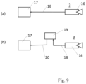
- Figure 9(a) illustrates the functionality of a first image sensor 16 and an alarm unit 17 according to the prior art.
- the first image sensor 16 is arranged with a first sensor effective range at a first location 3.
- the first image sensor 16 delivers first image data 18 to the alarm unit 17, which classifies the first image data 18 with regard to the occurrence of an unusual situation or a normal situation.
- the first image data 18 describe the respective situation sufficiently precisely that prior art methods, such as pattern recognition, can be applied to classify the situation.
- the Figure 9(b) illustrates an embodiment of the method according to the invention.
- the first image data 18 recorded by the first image sensor 16 are not sent to the alarm unit 17, but to a computer unit 19 for carrying out the method according to the invention.
- simulation data 20 comprising the first image data 18 created by the first image sensor 16 and object movement data are created.
- the simulation data 20 are forwarded to the alarm unit 17.
- the alarm unit 17 classifies the situation described by the simulation data 20 as a normal situation, an extraordinary situation, or an unclassifiable situation, with prior art methods being applied to the simulation data 20 for classifying the simulation data 20.
- the alarm unit 17 can, with reference to the above description, use the situation by means of pattern recognition or by applying methods based on artificial intelligence.
- the simulation data 20 is image data.
Landscapes
- Engineering & Computer Science (AREA)
- Physics & Mathematics (AREA)
- General Physics & Mathematics (AREA)
- Theoretical Computer Science (AREA)
- Human Computer Interaction (AREA)
- Multimedia (AREA)
- Health & Medical Sciences (AREA)
- Computer Security & Cryptography (AREA)
- Mechanical Engineering (AREA)
- Computer Vision & Pattern Recognition (AREA)
- General Health & Medical Sciences (AREA)
- Psychiatry (AREA)
- Social Psychology (AREA)
- Transportation (AREA)
- Automation & Control Theory (AREA)
- Image Analysis (AREA)
Claims (4)
- Procédé mis en œuvre par ordinateur pour déterminersi un système d'alarme reconnaît une situation exceptionnelle comme une telle situation et, le cas échéant, déclenche un signal d'alarme, lequel premier capteur d'images est un capteur virtuel et a une portée de capteur virtuelle qui comprend un premier endroit,dans lequel, à partir de données d'entrée telles que des plans d'une zone, des données de modèle de capteur d'image sont créées,lesdites données de modèle de capteur d'image décrivant au moins la portée de capteur virtuelle du premier capteur d'image sous la forme d'un modèle tridimensionnel,des données de simulation étant créées, dans une unité de calcul, en tant que données d'image comprenant les données de modèle de capteur d'image et les données de mouvement d'objet d'une personne (1) en tant qu'objet,les données de modèle de capteur d'image étant exemptes de la personne en mouvement (1), les données de mouvement d'objet, qui durent une période de temps, comprenant des données d'image créées à un deuxième moment concernant un mouvement réel de la personne (1) à un deuxième endroit, déterminé au moyen d'un deuxième capteur d'image réel, ou un mouvement virtuel de la personne à un deuxième endroit virtuel,caractérisé en ce queles données de mouvement d'objet décrivent le mouvement de la personne (1) par des mouvements individuels de parties sélectionnées de la personne (1) telles que les bras, les jambes, la tête,les données de simulation décrivant soit un événement ordinaire soit un événement exceptionnel étant transmises à une unité d'alarme traitant des données d'image,la situation décrite par les données de simulation comprenant les données de modèle de capteur d'image et les données de mouvement d'objet et se produisant dans la portée de capteur étant classée, dans l'unité d'alarme, comme un événement ordinaire ou comme un événement exceptionnel, respectivement, en utilisant des procédés de reconnaissance de formes et/ou des procédés de reconnaissance d'objets,les données de mouvement d'objet étant classifiées en tenant compte des mouvements individuels des parties de la personne,ledit système d'alarme émettant un signal d'alarme en cas d'événement exceptionnel,de sorte qu'il est possible de vérifier, à l'aide du signal d'alarme émis, si un système d'alarme déclenche un signal d'alarme pour des données de simulation, qui comprennent un événement exceptionnel.
- Procédé mis en œuvre par ordinateur pour déterminersi un système d'alarme reconnaît une situation exceptionnelle comme une telle situation et, le cas échéant, déclenche un signal d'alarme,lequel premier capteur d'image est un capteur d'image réel et a une portée de capteur réelle et lequel premier capteur d'image délivre des données de capteur d'image réellement détectées en tant que données d'image sur la portée de capteur à un premier moment,ladite portée de capteur comprenant un premier endroit,des données de simulation étant créées, dans l'unité de calcul, en tant que données d'image comprenant les données de capteur d'image et les données de mouvement d'objet d'une personne (1) en tant qu'objet,les données de capteur d'image étant exemptes de la personne en mouvement (1),les données de mouvement d'objet, qui durent une période de temps, comprenant des données d'image créées à un deuxième moment concernant un mouvement réel de la personne (1) à un deuxième endroit, déterminé au moyen d'un deuxième capteur d'image, ou un mouvement virtuel de la personne (1) à un deuxième endroit virtuel,caractérisé en ce queles données de mouvement d'objet décrivent le mouvement de la personne (1) par des mouvements individuels de parties sélectionnées de la personne (1) telles que les bras, les jambes ou la tête, les données de simulation décrivant soit un événement ordinaire soit un événement exceptionnel étant transmises à une unité d'alarme traitant des données d'image,une situation décrite par les données de simulation comprenant les données de modèle de capteur d'image et les données de mouvement d'objet, dans l'unité d'alarme, comme un événement ordinaire ou comme un événement exceptionnel, en utilisant des procédés de reconnaissance de formes et/ou des procédés de reconnaissance d'objets,les données de mouvement d'objet étant classifiées en tenant compte des mouvements individuels des parties de la personne,ledit système d'alarme émettant un signal d'alarme en cas d'événement exceptionnel,de sorte qu'il est possible de vérifier, à l'aide du signal d'alarme émis, si un système d'alarme déclenche un signal d'alarme pour des données de simulation, qui comprennent un événement exceptionnel.
- Procédé selon la revendication 1, caractérisé en ce queun seul modèle de capteur d'image est utilisé pour créer une pluralité de données de simulation différentes,lesdites données de simulation comprenant différentes données de mouvement d'objet et/ou lesdites données de simulation comprenant différentes données de modèle de capteur d'image.
- Procédé selon l'une des revendications 1 à 3, caractérisé en ce que
la période de temps des données de mouvement de l'objet entrant dans le procédé est différente d'une période de temps réelle du mouvement de l'objet.
Applications Claiming Priority (1)
| Application Number | Priority Date | Filing Date | Title |
|---|---|---|---|
| ATA50767/2020A AT524306B1 (de) | 2020-09-10 | 2020-09-10 | Modellierung einer Situation |
Publications (2)
| Publication Number | Publication Date |
|---|---|
| EP3968298A1 EP3968298A1 (fr) | 2022-03-16 |
| EP3968298B1 true EP3968298B1 (fr) | 2025-06-25 |
Family
ID=77666321
Family Applications (1)
| Application Number | Title | Priority Date | Filing Date |
|---|---|---|---|
| EP21195438.3A Active EP3968298B1 (fr) | 2020-09-10 | 2021-09-08 | Modélisation d'une situation |
Country Status (2)
| Country | Link |
|---|---|
| EP (1) | EP3968298B1 (fr) |
| AT (1) | AT524306B1 (fr) |
Family Cites Families (10)
| Publication number | Priority date | Publication date | Assignee | Title |
|---|---|---|---|---|
| DE10047082A1 (de) | 1999-10-07 | 2001-05-17 | Volkswagen Ag | Simulationssystem für ein Distanzregelungssystem |
| EP1696669B1 (fr) * | 2005-02-24 | 2013-07-03 | Aisin Seiki Kabushiki Kaisha | Dispositif de surveillance des environs d'un véhicule |
| GB0709329D0 (en) * | 2007-05-15 | 2007-06-20 | Ipsotek Ltd | Data processing apparatus |
| DE102008055932A1 (de) | 2008-11-05 | 2010-05-06 | Iav Gmbh Ingenieurgesellschaft Auto Und Verkehr | Verfahren zur modellbasierten Simulation eines Verhaltens eines Sensors |
| US9626566B2 (en) | 2014-03-19 | 2017-04-18 | Neurala, Inc. | Methods and apparatus for autonomous robotic control |
| DE102015205135A1 (de) | 2015-03-20 | 2016-09-22 | Bayerische Motoren Werke Ag | Verfahren zum Ermitteln eines für eine zumindest teilweise automatisierte Bewegung des Fahrzeugs nutzbaren Automatisierungsgrads |
| US10055652B2 (en) * | 2016-03-21 | 2018-08-21 | Ford Global Technologies, Llc | Pedestrian detection and motion prediction with rear-facing camera |
| CN107358191B (zh) * | 2017-07-07 | 2020-12-22 | 广东中星电子有限公司 | 视频报警检测方法和装置 |
| DE102018206805B3 (de) * | 2018-05-03 | 2019-09-12 | Robert Bosch Gmbh | Verfahren, Vorrichtung und Computerprogramm zum Prädizieren einer zukünftigen Bewegung eines Objekts |
| DE102019122790B4 (de) | 2018-08-24 | 2021-03-25 | Nvidia Corp. | Robotersteuerungssystem |
-
2020
- 2020-09-10 AT ATA50767/2020A patent/AT524306B1/de active
-
2021
- 2021-09-08 EP EP21195438.3A patent/EP3968298B1/fr active Active
Also Published As
| Publication number | Publication date |
|---|---|
| AT524306A1 (de) | 2022-03-15 |
| AT524306B1 (de) | 2022-09-15 |
| EP3968298A1 (fr) | 2022-03-16 |
Similar Documents
| Publication | Publication Date | Title |
|---|---|---|
| EP2297701B1 (fr) | Analyse vidéo | |
| DE69707886T2 (de) | Verfahren und gerät zum lokalisieren einer sich bewegenden zone und bestimmung der schnellheit und richtung der bewegung eines gebietes von relativer bewegung in einer szene | |
| DE102018121019A1 (de) | Erweitern von realen sensoraufzeichnungen mit simulierten sensordaten | |
| DE102007031302A1 (de) | Vorrichtung zur Erkennung und/oder Klassifizierung von Bewegungsmustern in einer Bildsequenz von einer Überwachungsszene, Verfahren sowie Computerprogramm | |
| DE102021128704A1 (de) | Verfahren und System zur Augmentierung von LIDAR-Daten | |
| WO2009049973A2 (fr) | Procédé pour créer et/ou actualiser des textures de modèles d'objets d'arrière-plan, système de vidéosurveillance pour la mise en œuvre du procédé, et programme informatique | |
| DE102011107458A1 (de) | Verfahren zum Evaluieren einer Objekterkennungseinrichtung eines Kraftfahrzeugs | |
| DE102019208735A1 (de) | Verfahren zum Betreiben eines Fahrassistenzsystems eines Fahrzeugs und Fahrerassistenzsystem für ein Fahrzeug | |
| WO2022106414A2 (fr) | Procédé et système pour annoter des données de capteur | |
| DE102021201445A1 (de) | Computerimplementiertes Verfahren zum Testen der Konformität zwischen realen und synthetischen Bildern für maschinelles Lernen | |
| DE102019208733A1 (de) | Verfahren und Generator zum Erzeugen von gestörten Eingangsdaten für ein neuronales Netz | |
| WO2022174952A1 (fr) | Procédé de paramétrage d'une synthèse d'image à partir d'un modèle 3d | |
| DE102010003336A1 (de) | Verfahren zur Visualisierung von Aktivitätsschwerpunkten in Überwachungsszenen | |
| AT525369B1 (de) | Testumfeld für urbane Mensch-Maschine Interaktion | |
| DE102022003079A1 (de) | Verfahren zu einer automatisierten Generierung von Daten für rasterkartenbasierte Prädiktionsansätze | |
| DE102018100667A1 (de) | Computersichtvorfusion und räumlich-zeitliche Verfolgung | |
| EP4007990B1 (fr) | Méthode d'analyse des informations d'image avec valeurs scalaires associées | |
| EP2679147B1 (fr) | Procédé et dispositif de codage de données de suivi de l'oeil et du regard | |
| EP3968298B1 (fr) | Modélisation d'une situation | |
| DE102008055932A1 (de) | Verfahren zur modellbasierten Simulation eines Verhaltens eines Sensors | |
| DE102021201178A1 (de) | Computerimplementiertes verfahren zum erzeugen von zuverlässigkeitsangaben für computervision | |
| EP3953862B1 (fr) | Procédé pour fournir une fonction de poursuite d'objet | |
| DE102013102528B4 (de) | Verfahren zur Bestimmung einer Verbauposition einer Innenraumsensorik in einem Fahrzeug | |
| EP3754544A1 (fr) | Système de détection, procédé de travail et procédé d'apprentissage | |
| DE102019102423A1 (de) | Verfahren zur Live-Annotation von Sensordaten |
Legal Events
| Date | Code | Title | Description |
|---|---|---|---|
| PUAI | Public reference made under article 153(3) epc to a published international application that has entered the european phase |
Free format text: ORIGINAL CODE: 0009012 |
|
| STAA | Information on the status of an ep patent application or granted ep patent |
Free format text: STATUS: THE APPLICATION HAS BEEN PUBLISHED |
|
| AK | Designated contracting states |
Kind code of ref document: A1 Designated state(s): AL AT BE BG CH CY CZ DE DK EE ES FI FR GB GR HR HU IE IS IT LI LT LU LV MC MK MT NL NO PL PT RO RS SE SI SK SM TR |
|
| STAA | Information on the status of an ep patent application or granted ep patent |
Free format text: STATUS: REQUEST FOR EXAMINATION WAS MADE |
|
| 17P | Request for examination filed |
Effective date: 20220905 |
|
| RBV | Designated contracting states (corrected) |
Designated state(s): AL AT BE BG CH CY CZ DE DK EE ES FI FR GB GR HR HU IE IS IT LI LT LU LV MC MK MT NL NO PL PT RO RS SE SI SK SM TR |
|
| STAA | Information on the status of an ep patent application or granted ep patent |
Free format text: STATUS: EXAMINATION IS IN PROGRESS |
|
| 17Q | First examination report despatched |
Effective date: 20230210 |
|
| GRAP | Despatch of communication of intention to grant a patent |
Free format text: ORIGINAL CODE: EPIDOSNIGR1 |
|
| STAA | Information on the status of an ep patent application or granted ep patent |
Free format text: STATUS: GRANT OF PATENT IS INTENDED |
|
| INTG | Intention to grant announced |
Effective date: 20250207 |
|
| GRAS | Grant fee paid |
Free format text: ORIGINAL CODE: EPIDOSNIGR3 |
|
| GRAA | (expected) grant |
Free format text: ORIGINAL CODE: 0009210 |
|
| STAA | Information on the status of an ep patent application or granted ep patent |
Free format text: STATUS: THE PATENT HAS BEEN GRANTED |
|
| AK | Designated contracting states |
Kind code of ref document: B1 Designated state(s): AL AT BE BG CH CY CZ DE DK EE ES FI FR GB GR HR HU IE IS IT LI LT LU LV MC MK MT NL NO PL PT RO RS SE SI SK SM TR |
|
| REG | Reference to a national code |
Ref country code: GB Ref legal event code: FG4D Free format text: NOT ENGLISH |
|
| REG | Reference to a national code |
Ref country code: CH Ref legal event code: EP |
|
| REG | Reference to a national code |
Ref country code: DE Ref legal event code: R096 Ref document number: 502021007828 Country of ref document: DE |
|
| REG | Reference to a national code |
Ref country code: CH Ref legal event code: EP |
|
| REG | Reference to a national code |
Ref country code: IE Ref legal event code: FG4D Free format text: LANGUAGE OF EP DOCUMENT: GERMAN |
|
| REG | Reference to a national code |
Ref country code: CH Ref legal event code: U11 Free format text: ST27 STATUS EVENT CODE: U-0-0-U10-U11 (AS PROVIDED BY THE NATIONAL OFFICE) Effective date: 20251001 |
|
| PG25 | Lapsed in a contracting state [announced via postgrant information from national office to epo] |
Ref country code: FI Free format text: LAPSE BECAUSE OF FAILURE TO SUBMIT A TRANSLATION OF THE DESCRIPTION OR TO PAY THE FEE WITHIN THE PRESCRIBED TIME-LIMIT Effective date: 20250625 |
|
| PGFP | Annual fee paid to national office [announced via postgrant information from national office to epo] |
Ref country code: DE Payment date: 20250729 Year of fee payment: 5 |
|
| REG | Reference to a national code |
Ref country code: LT Ref legal event code: MG9D |
|
| PG25 | Lapsed in a contracting state [announced via postgrant information from national office to epo] |
Ref country code: NO Free format text: LAPSE BECAUSE OF FAILURE TO SUBMIT A TRANSLATION OF THE DESCRIPTION OR TO PAY THE FEE WITHIN THE PRESCRIBED TIME-LIMIT Effective date: 20250925 Ref country code: GR Free format text: LAPSE BECAUSE OF FAILURE TO SUBMIT A TRANSLATION OF THE DESCRIPTION OR TO PAY THE FEE WITHIN THE PRESCRIBED TIME-LIMIT Effective date: 20250926 |
|
| PG25 | Lapsed in a contracting state [announced via postgrant information from national office to epo] |
Ref country code: BG Free format text: LAPSE BECAUSE OF FAILURE TO SUBMIT A TRANSLATION OF THE DESCRIPTION OR TO PAY THE FEE WITHIN THE PRESCRIBED TIME-LIMIT Effective date: 20250625 |
|
| PG25 | Lapsed in a contracting state [announced via postgrant information from national office to epo] |
Ref country code: HR Free format text: LAPSE BECAUSE OF FAILURE TO SUBMIT A TRANSLATION OF THE DESCRIPTION OR TO PAY THE FEE WITHIN THE PRESCRIBED TIME-LIMIT Effective date: 20250625 |
|
| PGFP | Annual fee paid to national office [announced via postgrant information from national office to epo] |
Ref country code: AT Payment date: 20251020 Year of fee payment: 5 |
|
| PG25 | Lapsed in a contracting state [announced via postgrant information from national office to epo] |
Ref country code: RS Free format text: LAPSE BECAUSE OF FAILURE TO SUBMIT A TRANSLATION OF THE DESCRIPTION OR TO PAY THE FEE WITHIN THE PRESCRIBED TIME-LIMIT Effective date: 20250925 |
|
| PG25 | Lapsed in a contracting state [announced via postgrant information from national office to epo] |
Ref country code: LV Free format text: LAPSE BECAUSE OF FAILURE TO SUBMIT A TRANSLATION OF THE DESCRIPTION OR TO PAY THE FEE WITHIN THE PRESCRIBED TIME-LIMIT Effective date: 20250625 |
|
| REG | Reference to a national code |
Ref country code: NL Ref legal event code: MP Effective date: 20250625 |
|
| PG25 | Lapsed in a contracting state [announced via postgrant information from national office to epo] |
Ref country code: NL Free format text: LAPSE BECAUSE OF FAILURE TO SUBMIT A TRANSLATION OF THE DESCRIPTION OR TO PAY THE FEE WITHIN THE PRESCRIBED TIME-LIMIT Effective date: 20250625 |
|
| PG25 | Lapsed in a contracting state [announced via postgrant information from national office to epo] |
Ref country code: PT Free format text: LAPSE BECAUSE OF FAILURE TO SUBMIT A TRANSLATION OF THE DESCRIPTION OR TO PAY THE FEE WITHIN THE PRESCRIBED TIME-LIMIT Effective date: 20251027 |
|
| P01 | Opt-out of the competence of the unified patent court (upc) registered |
Free format text: CASE NUMBER: UPC_APP_0013536_3968298/2025 Effective date: 20251114 |
|
| PG25 | Lapsed in a contracting state [announced via postgrant information from national office to epo] |
Ref country code: IS Free format text: LAPSE BECAUSE OF FAILURE TO SUBMIT A TRANSLATION OF THE DESCRIPTION OR TO PAY THE FEE WITHIN THE PRESCRIBED TIME-LIMIT Effective date: 20251025 |
|
| PG25 | Lapsed in a contracting state [announced via postgrant information from national office to epo] |
Ref country code: SM Free format text: LAPSE BECAUSE OF FAILURE TO SUBMIT A TRANSLATION OF THE DESCRIPTION OR TO PAY THE FEE WITHIN THE PRESCRIBED TIME-LIMIT Effective date: 20250625 |
|
| PGFP | Annual fee paid to national office [announced via postgrant information from national office to epo] |
Ref country code: CH Payment date: 20251001 Year of fee payment: 5 |
|
| PG25 | Lapsed in a contracting state [announced via postgrant information from national office to epo] |
Ref country code: CZ Free format text: LAPSE BECAUSE OF FAILURE TO SUBMIT A TRANSLATION OF THE DESCRIPTION OR TO PAY THE FEE WITHIN THE PRESCRIBED TIME-LIMIT Effective date: 20250625 |
|
| PG25 | Lapsed in a contracting state [announced via postgrant information from national office to epo] |
Ref country code: PL Free format text: LAPSE BECAUSE OF FAILURE TO SUBMIT A TRANSLATION OF THE DESCRIPTION OR TO PAY THE FEE WITHIN THE PRESCRIBED TIME-LIMIT Effective date: 20250625 |
|
| PG25 | Lapsed in a contracting state [announced via postgrant information from national office to epo] |
Ref country code: EE Free format text: LAPSE BECAUSE OF FAILURE TO SUBMIT A TRANSLATION OF THE DESCRIPTION OR TO PAY THE FEE WITHIN THE PRESCRIBED TIME-LIMIT Effective date: 20250625 |
|
| PG25 | Lapsed in a contracting state [announced via postgrant information from national office to epo] |
Ref country code: SK Free format text: LAPSE BECAUSE OF FAILURE TO SUBMIT A TRANSLATION OF THE DESCRIPTION OR TO PAY THE FEE WITHIN THE PRESCRIBED TIME-LIMIT Effective date: 20250625 |
|
| PG25 | Lapsed in a contracting state [announced via postgrant information from national office to epo] |
Ref country code: ES Free format text: LAPSE BECAUSE OF FAILURE TO SUBMIT A TRANSLATION OF THE DESCRIPTION OR TO PAY THE FEE WITHIN THE PRESCRIBED TIME-LIMIT Effective date: 20250625 |
|
| PG25 | Lapsed in a contracting state [announced via postgrant information from national office to epo] |
Ref country code: RO Free format text: LAPSE BECAUSE OF FAILURE TO SUBMIT A TRANSLATION OF THE DESCRIPTION OR TO PAY THE FEE WITHIN THE PRESCRIBED TIME-LIMIT Effective date: 20250625 |
|
| PG25 | Lapsed in a contracting state [announced via postgrant information from national office to epo] |
Ref country code: DK Free format text: LAPSE BECAUSE OF FAILURE TO SUBMIT A TRANSLATION OF THE DESCRIPTION OR TO PAY THE FEE WITHIN THE PRESCRIBED TIME-LIMIT Effective date: 20250625 |
|
| PG25 | Lapsed in a contracting state [announced via postgrant information from national office to epo] |
Ref country code: IT Free format text: LAPSE BECAUSE OF FAILURE TO SUBMIT A TRANSLATION OF THE DESCRIPTION OR TO PAY THE FEE WITHIN THE PRESCRIBED TIME-LIMIT Effective date: 20250625 |