EP3968312B1 - Autonomer sicherheitsblock - Google Patents
Autonomer sicherheitsblock Download PDFInfo
- Publication number
- EP3968312B1 EP3968312B1 EP21306232.6A EP21306232A EP3968312B1 EP 3968312 B1 EP3968312 B1 EP 3968312B1 EP 21306232 A EP21306232 A EP 21306232A EP 3968312 B1 EP3968312 B1 EP 3968312B1
- Authority
- EP
- European Patent Office
- Prior art keywords
- base
- pictogram
- label
- diffuser plate
- support element
- Prior art date
- Legal status (The legal status is an assumption and is not a legal conclusion. Google has not performed a legal analysis and makes no representation as to the accuracy of the status listed.)
- Active
Links
Images


Classifications
-
- G—PHYSICS
- G09—EDUCATION; CRYPTOGRAPHY; DISPLAY; ADVERTISING; SEALS
- G09F—DISPLAYING; ADVERTISING; SIGNS; LABELS OR NAME-PLATES; SEALS
- G09F13/00—Illuminated signs; Luminous advertising
- G09F13/04—Signs, boards or panels, illuminated from behind the insignia
- G09F13/0418—Constructional details
- G09F13/0456—Detachable casings
-
- G—PHYSICS
- G09—EDUCATION; CRYPTOGRAPHY; DISPLAY; ADVERTISING; SEALS
- G09F—DISPLAYING; ADVERTISING; SIGNS; LABELS OR NAME-PLATES; SEALS
- G09F13/00—Illuminated signs; Luminous advertising
- G09F13/04—Signs, boards or panels, illuminated from behind the insignia
- G09F13/0418—Constructional details
- G09F13/0436—Signs, boards or panels attached to ceilings
-
- G—PHYSICS
- G09—EDUCATION; CRYPTOGRAPHY; DISPLAY; ADVERTISING; SEALS
- G09F—DISPLAYING; ADVERTISING; SIGNS; LABELS OR NAME-PLATES; SEALS
- G09F13/00—Illuminated signs; Luminous advertising
- G09F13/04—Signs, boards or panels, illuminated from behind the insignia
- G09F13/0418—Constructional details
- G09F13/0458—Interchangeable panels
-
- G—PHYSICS
- G09—EDUCATION; CRYPTOGRAPHY; DISPLAY; ADVERTISING; SEALS
- G09F—DISPLAYING; ADVERTISING; SIGNS; LABELS OR NAME-PLATES; SEALS
- G09F13/00—Illuminated signs; Luminous advertising
- G09F13/18—Edge-illuminated signs
-
- G—PHYSICS
- G09—EDUCATION; CRYPTOGRAPHY; DISPLAY; ADVERTISING; SEALS
- G09F—DISPLAYING; ADVERTISING; SIGNS; LABELS OR NAME-PLATES; SEALS
- G09F27/00—Combined visual and audible advertising or displaying, e.g. for public address
- G09F27/004—Displays including an emergency or alarm message
-
- G—PHYSICS
- G09—EDUCATION; CRYPTOGRAPHY; DISPLAY; ADVERTISING; SEALS
- G09F—DISPLAYING; ADVERTISING; SIGNS; LABELS OR NAME-PLATES; SEALS
- G09F13/00—Illuminated signs; Luminous advertising
- G09F13/04—Signs, boards or panels, illuminated from behind the insignia
- G09F13/0418—Constructional details
- G09F2013/05—Constructional details indicating exit way or orientation
-
- G—PHYSICS
- G09—EDUCATION; CRYPTOGRAPHY; DISPLAY; ADVERTISING; SEALS
- G09F—DISPLAYING; ADVERTISING; SIGNS; LABELS OR NAME-PLATES; SEALS
- G09F13/00—Illuminated signs; Luminous advertising
- G09F13/18—Edge-illuminated signs
- G09F2013/184—Information to display
- G09F2013/1845—Interchangeable poster
Definitions
- the present invention relates to the technical field of autonomous emergency lighting blocks, and more particularly autonomous emergency lighting blocks which include a pictogram label.
- the present invention proposes an autonomous emergency lighting unit whose base can be installed both on a wall surface and on a ceiling surface, and which guarantees that the pictogram label is readable and visible in both types of installation.
- the autonomous security lighting block according to the invention forms a kit comprising all the parts necessary to install the autonomous security lighting block both on a wall surface or on a ceiling surface.
- the pictogram label can be mounted on the base in two possible orientations, depending on whether the mounting system, which cooperates with the support element carrying said pictogram label, is received in the first or in the second reception means of the base.
- the housing formed by the base and the diffuser plate is identical, only the orientation of the pictogram label on the housing is modified.
- an autonomous security lighting block 1 hereinafter referred to as block 1, intended to illuminate premises in the event of a power cut to the main electrical circuit supplying said premises.
- a block 1 comprises more precisely, on the one hand, a box 10 intended to illuminate the premises and to provide a light reference point for users, and, on the other hand, a pictogram label 40 intended to indicate, in the event of if necessary, the emergency exits closest to block 1 to users of the premises.
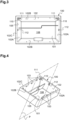
- the housing 10 comprises, on the one hand, a base 100 (see figures 3 and 4 ) which houses electrical and/or electronic elements (not shown) of block 1 such as power batteries, an electronic card and LED (Light Emitting Diode) type light sources, and, on the other hand, a plate diffuser 150 (see Figure 5 ) of a light beam which closes, at the front, the base 100 (see figures 9 And 12 ).
- a base 100 see figures 3 and 4
- electrical and/or electronic elements not shown
- block 1 such as power batteries, an electronic card and LED (Light Emitting Diode) type light sources
- a plate diffuser 150 see Figure 5
- the light sources of block 1 are housed inside the base 100 of the housing 10 so that the light sources are fixed relative to the base 100 of the housing 10 of block 1.
- the orientation of the light beam generated by these light sources, through the diffuser plate 150 closing the base 100, is thus imposed by the orientation of the base 100.
- the base 100 of the housing 10 is here molded in one piece from insulating plastic material.
- the base 100 is capable of being mounted projecting onto a mounting surface such as a ceiling surface or a wall surface.
- a mounting surface such as a ceiling surface or a wall surface.
- the base it is possible for the base to be able to be mounted recessed in a mounting surface, in particular in a false ceiling, via a recessed accessory.
- the expression “capable of being mounted on a mounting surface” encompasses the two possible installations of the base, projecting on the mounting surface or recessed in said mounting surface.
- front and rear will be defined in relation to the user's gaze turned towards the block 1 installed on the chosen mounting surface.
- front will designate the side of block 1 facing the user
- rear will designate the side of block 1 facing away from it.
- the base 100 has a generally parallelepiped shape.
- the base 100 comprises an internal side wall 102 which rises by flaring from a bottom wall 101, so as to form a slightly obtuse angle with said bottom wall 101.
- the internal side wall 102 follows the contour rectangular of the bottom wall 101 so as to form two short transverse sides 102A facing each other and two long longitudinal sides 102B facing each other.
- the internal side wall 102 and the bottom wall 101 of the base 100 thus delimit an interior space 108 in which said electrical and/or electronic elements of block 1 are housed.
- the base 100 is open at the front. More precisely, a front edge 102C of said internal side wall 102 delimits a rectangular opening 105. This rectangular opening 105 is intended to be closed by the diffuser plate 150 mounted on or in the base 100.
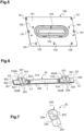
- said diffuser plate 150 comprises a main plate 151 with a rectangular outline, having in its center an oblong recess 152 which extends in depth towards the rear from the front face of the diffuser plate 150, and in length along a central longitudinal axis of the diffuser plate 150.
- This oblong recess 152 has reflective properties, so as to reflect the light in all directions and in particular towards the front of the diffuser plate 150
- the main plate 151 is pierced, in the center of the oblong recess 152, an opening 153, also of oblong shape.
- This opening 153 is intended to be closed, from the rear, that is to say from the interior space 108 of the base 100, by the electronic card (not shown) carrying the light sources (not shown), so that said light sources extend through the opening 153, in the oblong recess 152.
- Legs 155 extend perpendicular to the rear face of the main plate 151 (see figure 5 ) on either side of the oblong recess 152, so as to receive said electronic card carrying the light sources.
- the diffuser plate 150 further comprises a diffusing element 154, arranged at the front of the oblong recess 152 so as to be flush with the front face of the main plate 151 along the edge which delimits said oblong recess 152.
- the diffuser plate 150 comprising the main plate 151 whose oblong recess 152 is closed at the front by the diffusing element 154 thus has a flat front surface.
- the diffusing element 154 encloses the light sources in said oblong recess 152, and diffuses the light they generate homogeneously towards the outside of the housing 10.
- the internal side wall 102 of the base 100 is provided, near its front edge 102C, along the two long longitudinal sides 102B, with uprights 103 forming support brackets. support of the diffuser plate 150.
- the diffuser plate 150 cannot easily be separated from the base 100.
- the dimensions of the diffuser plate 150 are such that it is retracted slightly forcefully into the rectangular opening 105 of the base 100.
- the base 100 of the housing 10 also includes an external side wall 104 which borders laterally, from the outside, the front edge 102C of the internal side wall 102 of the base 100 and which surrounds the internal side wall 102 of the base 100.
- This wall external side 104 forms a finishing wall. It extends at a distance from the internal side wall 102 so that a rear space 106 is delimited between the internal side wall 102 and the external side wall 104.
- This rear space 106 is intended to accommodate means for fixing the base 100 on the mounting surface.
- This external side wall 104 has straight external and internal faces, so that externally the base 100 has a rectangular parallelepiped shape.
- the box 10 alone is thus sufficient to use the block 1 to illuminate the premises.
- the block 1 also includes a support element 30 (see figures 1, 2 And 6 ). It is advantageous to be able to fix the pictogram label 40 to the outside of the housing 10 insofar as the pictogram label 40 can thus have dimensions, in width and length, greater than those of the housing 10. Like the dimensions of the pictogram label conditions, in a normative manner, the spacing between two blocks 1 indicating the emergency exits in said premises, using sufficiently large labels makes it possible to further space the blocks 1 in the premises.
- the support element 30 comprises (see Figure 6 ), on the one hand, a strip 300 extending along a longitudinal axis L, which is intended to be assembled with the pictogram label 40, and, on the other hand, assembly means 310 intended to fixedly hold the pictogram label against the strip 300.
- the strip 300 is formed by a flat profile with a U-shaped section which internally delimits a longitudinal groove 301 (see Figure 6 ) intended to receive part of the pictogram label 40 (see figures 1 and 2 ).
- the pictogram label 40 is installed in the longitudinal groove 301 so as to abut against the bottom of this longitudinal groove 301, formed by the internal face of the back 303 of the profile.
- the assembly means are here formed by two openings 310 which pass right through the parallel longitudinal wings 302 of the profile.
- the openings 310 are intended to receive assembly elements (not shown) such as retaining screws or rivets which securely hold the pictogram label 40 in the longitudinal groove 301 of the support element 30.
- assembly elements can be considered, in a conventional manner in itself.
- the pictogram label 40 generally parallel to the diffuser plate 150, for installation of the block 1 on a wall surface ( figure 1 ), or generally perpendicular to the diffuser plate 150 for installation of block 1 on a ceiling surface ( figure 2 ).
- the pictogram label 40 is always, on the one hand, illuminated by the diffuser plate 150, and, on the other hand, oriented in a way that is readable for users.
- the intermediate mounting system 20 can be received in two reception means 110, 112 distinct from the base 100, and the support element 30 can be arranged in two possible orientations (see figures 1 and 2 ) on said intermediate mounting system 20 depending on whether said intermediate mounting system 20 is received in one or other of said receiving means 110, 112 of the base 100 so that the pictogram label 40 is illuminated by said diffuser plate 150 and oriented in a legible manner for users whatever the surface on which block 1 is installed.
- the first receiving means 110 of the base 100 comprises a pair of housings 110 facing each other, formed hollow in the internal face of the internal side wall 102 of the base 100 so as to open towards the inside of the base 100, it that is to say in the interior space 108 of the base 100.
- These housings 110 extend on the short transverse sides 102A of the internal side wall 102 and adjoin one of the long longitudinal sides 102B of the base 100.
- Each housing 110 of the first receiving means communicates with a notch 111 formed hollow in the internal face of the internal side wall 102 of the base 100.
- Each notch 111 extends on said long longitudinal side 102B which adjoins said housings 110, and opens out also towards the inside of the base 100.
- the second receiving means 112 of the base 100 comprises a pair of housings 112 facing each other, formed hollow in the internal face of the internal side wall 102 of the base 100 so as to open towards the inside of the base 100 , that is to say in the interior space 108 of the base 100.
- These housings 112 extend also on the short transverse sides 102A of the internal side wall 102. They are positioned along a median plane P of the base 100 perpendicular to the rectangular opening 105 (see figure 4 ).
- the intermediate mounting system 20 comprises a pair of mounting elements 200 such as that shown in the Figure 7 .
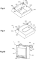
- the two mounting elements 200 of the intermediate mounting system 20 are identical and each form, on the one hand, a foot 201 adapted to be received in one of said first or second receiving means 110, 112 of the base 100 of the housing 10 (see figures 8 And 11 ), and, on the other hand, a head 202 adapted to cooperate with the fixing means 335, 337 of the support element 30 (see figures 10 And 13 ).
- Each mounting element 200 is here molded in one piece from insulating plastic material.
- each mounting element 200 has a generally rectangular parallelepiped shape.
- the foot 201 forms a slide intended to be inserted by sliding into the housings 110, 112 of the first or second means for receiving the base 100.
- the foot 201 of each mounting element 200 here has a cubic shape and the housings 110, 112 in hollow of the base 100 have a corresponding cubic shape.
- other shapes are possible for the feet 201 and the housings 110, 112, as long as said shapes are complementary to each other.
- the feet 201 of the two mounting elements 200 of the intermediate mounting system 20 are inserted, here by sliding, into the housings 110 of the base 100.
- the notches 111 communicating with the housings 110 make it possible to insert the feet 201 despite, d 'on the one hand the proximity of the housing 110 with the long longitudinal side 102B of the internal side wall 102 of the base 100, and, on the other hand, the inclination of said internal side wall 102 which extends flaring from the bottom wall 101 towards the rectangular opening 105.
- the feet 201 are slid into the notches 111 until they are engaged in the housings 110 of the base 100.
- the feet 201 of the two mounting elements 200 of the intermediate mounting system 20 are inserted, here by sliding, into the housings 112 of the base 100.
- the head 202 of said mounting element 200 extends forward, in the extension of the front edge 102C of the wall internal side 102 of the base 100 (see figures 8 And 11 ).
- the foot 201 of the mounting element 200 comprises, in its front part connecting it to the head 202, a notch 203 (see Figure 7 ) intended to receive the front edge 102C of the internal side wall 102 of the base 100 so that the mounting element 200 bites said front edge 102C when it is inserted into the housing 110, 112 of the base 100 (see figures 8 and 10 ).
- the housings 110, 112 of the first and second means of receiving the base 100 it is advantageous for the housings 110, 112 of the first and second means of receiving the base 100 to open exclusively inside the base 100 because this guarantees that the feet 201 of the mounting elements 200 cannot be dismantled by unauthorized persons. once the base 100 is closed by the diffuser plate 150. It is in fact preferable that the pictogram label 40 is assembled in a fixed and immovable manner on the housing 10 of the block 1 so as to guarantee that the evacuation paths put in place are not easily modifiable once they have been validated by the safety commissions.
- the main plate 151 of the diffuser plate 150 has on its outer peripheral edge notches 156 intended to be crossed by the mounting elements 200 of the intermediate mounting system 20 received in the housings 110, 112 of the base 100.
- the notches 156 are located on the external peripheral edge of the main plate 151 so that when the diffuser plate 150 is attached to the rectangular opening 105 of the base 100, said notches are located to the right of the housings 110, 112 of the base 100 in a perpendicular direction to the diffuser plate 150.
- the notches 156 here have a generally rectangular shape, which corresponds, to the nearest clearance, to the section of the head 202 of the mounting elements 200.
- the diffuser plate 150 can be easily attached to the base 100 of the housing 10 equipped with the mounting elements 200. Despite the mounting elements 200 which pass through the diffuser plate 150, the housing 10 remains entirely closed, at the front, by the diffuser plate 150.
- the main plate 151 of the diffuser plate 150 advantageously comprises, along its external peripheral edge, on the rear face of the main plate 151, zones of lower resistance delimiting breakable parts adapted to be cut to form said notches 156 of the diffuser plate 150.
- the zones of Smaller thicknesses are formed by cutting or breaking lines 157.
- the cutting or breaking lines 157 here follow a rectangular contour corresponding to the contour of the notches 156.
- the lines 157 of lower resistance of the main plate 151 of the diffuser plate 150 located in the corners of said main plate 151 are cut when the block 1 is intended for wall mounting, so that the diffuser plate 150 attached to the rectangular opening 105 can be traversed by the mounting elements 200 received in the housings 110 of the base 100 ( Figure 9 ).
- the lines 157 of lower resistance of the main plate 151 located in the middle of the two short transverse sides of said main plate 151 are cut, so that the diffuser plate 150 attached in the The rectangular opening 105 of the base 100 can be crossed by the mounting elements 200 received in the housings 112 of the base 100 ( Figure 12 ).
- the same main plate 151 of the diffuser plate 150 is used to close the base 100, whether the block 1 is intended for wall installation or for ceiling installation, without the diffuser plate 150 having unused notches which would give access to the interior of housing 10.
- the head 202 of each mounting element 200 has a generally parallelepiped shape. As will be explained later, the head 202 of each mounting element 200 is crossed, right through, by a through opening 204 with a view to the cooperation of said head 202 of the mounting element 200 with the fixing means 335, 337 of the support element 30. the through opening 204 extends generally longitudinally in the head 202 of each mounting element 200.
- the support element 30 comprises a pair of stirrups 331 intended to receive the head 202 of each mounting element 200 of the intermediate mounting system 20.
- the support element 30 is here molded in a single piece of material insulating plastic. More precisely, the strip 300 and the pair of stirrups 331 belong to the same single piece molded from plastic material.
- each stirrup 331 extends on the same face of one of the longitudinal wings 302 of the strip 300 of the support element 30.
- each stirrup 331 comprises two branches 332 extending opposite each other, generally perpendicular to said face of the longitudinal wing 302 from the back 303 of the profile of the strip 300 to the free edge of said longitudinal wing 302
- each branch 332 comprises a first return 332A which extends perpendicularly to the back 303 of the profile of the strip 300 and a second return 332B which extends perpendicularly to the free edge of said corresponding longitudinal wing 302 of the strip 300.
- Each stirrup 331 internally delimits, between said branches 332, a groove intended to receive the head 202 of the corresponding mounting element 200.
- the support element 30 comprises two distinct fixing means, carried by said stirrups 331: a first fixing means 335 adapted to cooperate with said intermediate mounting system 20 in order to maintain the pictogram label 40 in the plane substantially parallel to the diffuser plate 150 and a second fixing means 337, distinct from the first fixing means 335, adapted to cooperate with said intermediate mounting system 20 in order to maintain the pictogram label 40 in the plane substantially perpendicular to the diffuser plate 150.
- each fixing means 335, 337 of the support element 30 comprises an opening 335, 337 in each of the two branches 332 facing each stirrup 331.
- the openings 335, 337 of the same means of fixing face each other on the stirrup 331.
- the openings 335, 337 of the same fixing means are intended to communicate with the through opening 204 provided in the head 202 of the mounting element 200 received in the groove of said stirrup 331 so that said openings 335, 337, aligned with the through opening 204, form a conduit for receiving a fixing element (not shown) intended to fixedly hold the head 202 of the mounting element 200 in said groove of said stirrup 331.
- the fixing element here is a screw, but could also be formed by a rivet or any other conventional fixing element in itself.
- the openings 335 facing the first means of fixing the support element 30 are centered on a common axis C1 which extends parallel to the longitudinal axis L of the strip 300, said common axis C1 being offset relative to the longitudinal axis L of the strip 300. to the extension plane of the pictogram label 40 received in the longitudinal groove 301 of the strip 300.
- the openings 335 of the first fixing means are carried by the branches 332 of each stirrup 331, to the right of the second return 332B of said branches 332 (see Figure 6 ).
- the openings 337 facing the second means of fixing the support element 30 are centered on a common axis C2 which extends parallel to the longitudinal axis L of the strip 300, said common axis C2 being included in the extension plane of the pictogram label 40 received in the longitudinal groove 301 of the strip 300.
- the openings 337 of the second fixing means are carried by the first return 332A of the branches 332 of each stirrup 331 (see Figure 6 ).
- each stirrup 331 is attached to the head 202 of one of the mounting elements 200 so that, in a on the other hand, that said head 202 is engaged in the groove of said stirrup 331, and, on the other hand, that the through opening 204 of the head 202 is aligned with the openings 335 of the stirrup 331.
- a fixing element, of screw type, must then be inserted into each receiving conduit formed by the alignment of said openings 335 with the through opening 204 so as to secure the support element 30 to the housing 10.
- the housing 10 of the block 1 has its base 100 closed at the front by the diffuser plate 150, at the front of which emerge the heads 202 of the mounting elements 200 whose feet are mounted in said housings of the base 100.
- the edges of the notches 156 of the main plate 151 of the diffuser plate 150 surround the mounting elements 200 as closely as possible so as to prevent the tip of any tool from being introduced inside the base 100.
- the heads 202 of the mounting elements 200 projecting from the front face of the diffuser plate 150 are then easily accessible for mounting the support element 30 in which the pictogram label 40 is fixed.
- each stirrup 331 is attached to the head 202 of one of the mounting elements 200 so that, on the one hand, said head 202 is engaged in the groove of the stirrup 331 and, on the other hand, that the through opening 204 of the head 202 is aligned with the openings 337 of the stirrup 331 (see figure 13 ).
- a fixing element (not shown), of the screw type, must then be inserted into each receiving conduit formed by the alignment of said openings 337 with the through opening 204 so as to secure the support element 30 to the housing 10.
- the pictogram label 40 is inserted into the longitudinal groove 301 of the strip 300 and held fixedly at the bottom of the longitudinal groove 301, abutting against the bottom of the longitudinal groove 301 of the strip 300, by axes inserted in the openings 310 of the strip 300 (see figures 1 and 2 ).
- the pictogram label 40 is fixed with the support element 30 before the support element 30 is attached to the heads 202 of the mounting elements 200 of the intermediate mounting system 20.
- it is the sub -assembly formed by the pictogram label 40 fixed on the support element 30 which is attached to the subassembly formed by the housing 10 from which the heads 202 of the mounting elements 200 emerge.
- the pictogram label 40 carried by said support element 30 can extend either parallel to the diffuser plate 150 while completely covering said diffuser plate 150 (see figure 2 ) so as to be uniformly illuminated by said diffuser plate 150, or perpendicular to the diffuser plate 150 in the median plane of the housing 10 extending perpendicular to the rectangular opening 105 of the base 100 of said housing 10 (see figure 1 ), so as to be illuminated on both sides by the diffuser plate 150.
- the branches 332 of the stirrups 331 keep it at a distance from said diffuser plate 150, which improves the uniform illumination of the pictogram label 40.
- the block 1 according to the invention forms a universal kit whose parts can be assembled according to two configurations which make the block 1 compatible both for fixing to a ceiling and for fixing to a wall, whether this fixing is protruding or recessed.
- the support element comprises a single fixing means, formed by openings facing each other in the branches of each stirrup. These openings are arranged to the right of the first return of the branches, so that the axis on which they are centered extends parallel to the longitudinal axis of the strip, in a plane offset from the extension plane of the pictogram label 40 received in the longitudinal groove of the strip.
- the strip is also possible for the strip to be formed by a single longitudinal wing rather than by a flattened U-shaped profile comprising two longitudinal wings connected by the back of the profile.
- the base of the block has a shape other than parallelepiped.
- the means of assembling the support element with the pictogram label are formed by other known assembly means, such as glue, or magnets.
- the mounting elements of the intermediate mounting system are replaced by visible screws, by clips or even by magnets.
Landscapes
- Physics & Mathematics (AREA)
- General Physics & Mathematics (AREA)
- Engineering & Computer Science (AREA)
- Theoretical Computer Science (AREA)
- Business, Economics & Management (AREA)
- Emergency Management (AREA)
- Non-Portable Lighting Devices Or Systems Thereof (AREA)
Claims (13)
- Autonomer Sicherheitsbeleuchtungsblock (1) mit:einem Gehäuse (10), das einen Sockel (100), der geeignet ist, auf einer Montageoberfläche montiert zu werden, und eine Streuplatte (150) für einen Lichtstrahl, die das Vordere des Sockels (100) abschließt, aufweist, undeinem Trägerelement (30) für die Befestigung eines Piktogrammschilds (40) an der Außenseite des Gehäuses (10),dadurch gekennzeichnet, daß- mindestens ein Zwischenmontagesystem (20) vorgesehen ist,- das Trägerelement (30) mindestens ein Befestigungsmittel (335, 337) aufweist, um mit dem Zwischenmontagesystem (20) zusammenzuwirken, und- der Sockel (100) einerseits ein erstes Aufnahmemittel (110), das dazu ausgelegt ist, das Zwischenmontagesystem (20) aufzunehmen, so daß es mit dem Befestigungsmittel (335, 337) des Trägerelements (30) zusammenwirkt, um das Piktogrammschild (40) in einer zur Streuplatte (150) des Gehäuses (10) im Wesentlichen parallelen Ebene zu halten, und andererseits ein vom ersten Aufnahmemittel (110) verschiedenes zweites Aufnahmemittel (112), das dazu ausgelegt ist, das Zwischenmontagesystem (20) aufzunehmen, so daß es mit dem Befestigungsmittel (335, 337) des Trägerelements (30) zusammenwirkt, um das Piktogrammschild (40) in einer zur Streuplatte (150) des Gehäuses (10) im Wesentlichen im rechten Winkel liegenden Ebene zu halten, aufweist.
- Autonomer Sicherheitsbeleuchtungsblock (1) gemäß Anspruch 1, bei dem das Trägerelement (30) ein erstes Befestigungsmittel (335), das dazu ausgelegt ist, mit dem Zwischenmontagesystem (20) zusammenzuwirken, um das Piktogrammschild (40) in der zur Streuplatte (150) im Wesentlichen parallelen Ebene zu halten, und ein vom ersten Befestigungsmittel (335) verschiedenes zweites Befestigungsmittel (337), das dazu ausgelegt ist, mit dem Zwischenmontagesystem (20) zusammenzuwirken, um das Piktogrammschild (40) in der zur Streuplatte (150) im Wesentlichen im rechten Winkel liegenden Ebene zu halten, aufweist.
- Autonomer Sicherheitsbeleuchtungsblock (1) gemäß einem der Ansprüche 1 und 2, bei dem das Zwischenmontagesystem (20) ein Paar identische Montageelemente (200) aufweist, die jeweils einerseits einen Fuß (201), der dazu ausgelegt ist, in einem der ersten oder zweiten Aufnahmemittel (110, 112) des Sockels (100) des Gehäuses (10) aufgenommen zu werden, und andererseits einen Kopf (202), der dazu ausgelegt ist, mit jedem Befestigungsmittel (335, 337) des Trägerelements (30) zusammenzuwirken, aufweisen.
- Autonomer Sicherheitsbeleuchtungsblock (1) gemäß Anspruch 3, bei dem das Trägerelement (30)- eine sich entlang einer Längsachse (L) erstreckende Leiste (300), die dazu bestimmt ist, mit dem Piktogrammschild (40) zusammengefügt zu werden,- Zusammenfügungsmittel (310), die dazu bestimmt sind, das Piktogrammschild (40) fest an der Leiste (300) zu halten, und- ein Paar Halterungen (331), die dazu bestimmt sind, den Kopf (202) jedes Montageelements (200) des Zwischenmontagesystems (20) aufzunehmen, wobei sich jede Halterung (331) auf einer selben Seite der Leiste (300) erstreckt, aufweist.
- Autonomer Sicherheitsbeleuchtungsblock (1) gemäß Anspruch 4, bei dem jedes Befestigungselement des Trägerelements (30) in jedem der beiden Zweige (332) gegenüber jeder Halterung (331) eine Öffnung (335, 337) aufweist, wobei die Öffnungen (335, 337) jeder Halterung (331) einander gegenüber liegen und dazu bestimmt sind, mit einer im Kopf (202) des Montageelements (200) vorgesehenen Durchgangsöffnung (204) zu kommunizieren, die in der Halterung (331) aufgenommen ist, so daß die mit der Durchgangsöffnung (204) zusammen ausgerichteten Öffnungen (335, 337) eine Aufnahmeleitung für ein Befestigungselement bilden, das dazu bestimmt ist, den Kopf (202) des Montageelements (200) fest in der Halterung (331) zu halten.
- Autonomer Sicherheitsbeleuchtungsblock (1) gemäß den Ansprüchen 2 und 5, bei dem die Öffnungen (335) gegenüber dem ersten Befestigungsmittel des Trägerelements (30) auf einer gemeinsamen Achse (C1) zentriert sind, die sich parallel zur Längsachse (L) der Leiste (300) erstreckt, wobei die gemeinsame Achse (C1) gegenüber der Erstreckungsebene des Piktogrammschilds (40) versetzt ist.
- Autonomer Sicherheitsbeleuchtungsblock (1) gemäß den Ansprüchen 2 und 5 oder 6, bei dem die Öffnungen (337) gegenüber dem zweiten Befestigungsmittel des Trägerelements auf einer gemeinsamen Achse (C2) zentriert sind, die sich parallel zur Längsachse (L) der Leiste (300) erstreckt, wobei die gemeinsame Achse (C2) in der Erstreckungsebene des Piktogrammschilds (40) enthalten ist.
- Autonomer Sicherheitsbeleuchtungsblock (1) gemäß einem der Ansprüche 4 bis 7, bei dem die Leiste (300) durch ein flaches Profil mit U-Querschnitt gebildet ist, das im Inneren eine Längsrinne (301) begrenzt, die dazu bestimmt ist, einen Teil des Piktogrammschilds (40) aufzunehmen.
- Autonomer Sicherheitsbeleuchtungsblock (1) gemäß einem der Ansprüche 1 bis 8, bei dem der Sockel (100) eine Seitenwand (102) aufweist, die sich von einer Bodenwand (101) aus erhebt und einer im Wesentlichen rechtwinkligen Kontur folgt, um zwei kleine Querseiten (102A) und zwei große Längsseiten (102B) zu bilden und damit der vordere Rand (102C) der Seitenwand (102) eine rechteckige Öffnung (105) begrenzt, die dazu bestimmt ist, die Streuplatte (150) aufzunehmen, und bei dem das zweite Aufnahmemittel des Sockels (100) ein Paar sich gegenüberliegender Aufnahmen (112) aufweist, die als Aushöhlung in der Seitenwand (102) des Sockels (100) gebildet sind, um zum Inneren des Sockels (100) hin offen zu sein, wobei sich die Aufnahmen über die kleinen Querseiten (102A) der Seitenwand (102) erstrecken und entlang einer Mittelebene (P) des Sockels (100) senkrecht zur rechteckigen Öffnung (105) angeordnet sind.
- Autonomer Sicherheitsbeleuchtungsblock (1) gemäß einem der Ansprüche 1 bis 9, bei dem der Sockel (100) eine Seitenwand (102) aufweist, die sich von einer Bodenwand (101) aus erhebt und einer im Wesentlichen rechteckigen Kontur folgt, um zwei kleine Querseiten (102A) und zwei große Längsseiten (102B) zu bilden, und so, daß der vordere Rand (102C) der Seitenwand (102) eine rechteckige Öffnung (105) begrenzt, die dazu bestimmt ist, die Streuplatte (150) aufzunehmen, und bei dem das erste Aufnahmemittel des Sockels ein Paar sich gegenüber liegender Aufnahmen (110) aufweist, die hohl in der Seitenwand (102) des Sockels (100) gebildet sind, um zum Inneren des Sockels (100) hin zu münden, wobei sich die Aufnahmen (110) auf den kleinen Querseiten (102A) der Seitenwand (102) erstrecken und an eine der großen Längsseiten (102B) des Sockels (100) grenzen.
- Autonomer Sicherheitsbeleuchtungsblock (1) gemäß Anspruch 10, bei dem jede Aufnahme (110) des ersten Aufnahmemittels mit einem in der Seitenwand (102) des Sockels (100) hohl gebildeten Spalt (111) kommuniziert und zum Inneren des Sockels (100) hin mündet, wobei sich jeder Spalt (111) auf der großen Längsseite (102B) erstreckt, die an die Aufnahmen (110) angrenzen.
- Autonomer Sicherheitsbeleuchtungsblock (1) gemäß einem der Ansprüche 1 bis 11, bei dem die Streuplatte (150) Spalte (156) aufweist, die dazu bestimmt sind, von dem Zwischenmontagesystem (20) durchquert zu werden.
- Autonomer Sicherheitsbeleuchtungsblock (1) gemäß Anspruch 12, bei dem die Streuplatte (150) entlang ihres Umfangrands Zonen (157) mit geringerer Festigkeit aufweist, die abtrennbare Teile bilden und geeignet sind, abgetrennt zu werden, um die Spalte (156) der Streuplatte (150) zu bilden.
Priority Applications (1)
| Application Number | Priority Date | Filing Date | Title |
|---|---|---|---|
| MA58261A MA58261B1 (fr) | 2020-09-15 | 2021-09-09 | Bloc autonome de securite |
Applications Claiming Priority (1)
| Application Number | Priority Date | Filing Date | Title |
|---|---|---|---|
| FR2009352A FR3114140B1 (fr) | 2020-09-15 | 2020-09-15 | Bloc autonome de sécurité |
Publications (3)
| Publication Number | Publication Date |
|---|---|
| EP3968312A1 EP3968312A1 (de) | 2022-03-16 |
| EP3968312C0 EP3968312C0 (de) | 2024-07-24 |
| EP3968312B1 true EP3968312B1 (de) | 2024-07-24 |
Family
ID=73401803
Family Applications (1)
| Application Number | Title | Priority Date | Filing Date |
|---|---|---|---|
| EP21306232.6A Active EP3968312B1 (de) | 2020-09-15 | 2021-09-09 | Autonomer sicherheitsblock |
Country Status (3)
| Country | Link |
|---|---|
| EP (1) | EP3968312B1 (de) |
| FR (1) | FR3114140B1 (de) |
| MA (1) | MA58261B1 (de) |
Family Cites Families (5)
| Publication number | Priority date | Publication date | Assignee | Title |
|---|---|---|---|---|
| US6241369B1 (en) * | 1998-11-20 | 2001-06-05 | Cooper Technologies Company | Quick mount fixture |
| FR2874990B1 (fr) * | 2004-09-06 | 2006-12-08 | Legrand Sa | Appareillage electrique mural a double sens de montage |
| DE202008008977U1 (de) | 2008-07-04 | 2009-11-19 | Pasedag, Roland | Beleuchtungskörper, insbesondere in der Form einer Rettungszeichenleuchte |
| DE202010009487U1 (de) * | 2010-06-24 | 2010-10-07 | Ridi-Leuchten Gmbh | Befestigungsvorrichtung |
| FR3077915B1 (fr) * | 2018-02-09 | 2020-02-28 | Cooper Securite Sas | Bloc d'eclairage de securite configurable |
-
2020
- 2020-09-15 FR FR2009352A patent/FR3114140B1/fr active Active
-
2021
- 2021-09-09 MA MA58261A patent/MA58261B1/fr unknown
- 2021-09-09 EP EP21306232.6A patent/EP3968312B1/de active Active
Also Published As
| Publication number | Publication date |
|---|---|
| EP3968312C0 (de) | 2024-07-24 |
| FR3114140A1 (fr) | 2022-03-18 |
| EP3968312A1 (de) | 2022-03-16 |
| MA58261B1 (fr) | 2024-09-30 |
| FR3114140B1 (fr) | 2023-04-28 |
Similar Documents
| Publication | Publication Date | Title |
|---|---|---|
| EP3525198B1 (de) | Konfigurierbarer sicherheitsbeleuchtungsblock | |
| EP4279342A1 (de) | Vorrichtung zum verbinden eines wischblatts | |
| EP3968312A1 (de) | Autonomer sicherheitsblock | |
| EP2718512B1 (de) | Leuchtende glasstrennwand | |
| FR3060101A1 (fr) | Dispositif de connexion de luminaire | |
| EP1744427B1 (de) | Gehäuse eines elektrischen Gerätes mit verstellbarer Tiefe | |
| EP3286497A1 (de) | Planare montagevorrichtung mit beleuchtung | |
| EP1164676B1 (de) | Vorrichtung zur Befestigung eines elektrischen Geräts auf einem Kabelkanal | |
| FR3058502B1 (fr) | Dispositif de montage sans vis d'un boitier de commande de projecteur sur ledit projecteur | |
| FR3088869A1 (fr) | Dispositif de pré-positionnement et de maintien d’un élément sur un boitier | |
| EP3553904B1 (de) | Befestigungsvorrichtung eines steuer- und/oder signalisierungsorgans | |
| EP1160414A1 (de) | Endhalterung für eine Wickelwelle, Verfahren zur Herstellung und Antriebsmechanismus einer Schliess- oder Sonnenschutzeinrichtung mit solcher Vorrichtung | |
| EP3421876B1 (de) | Beleuchtungssystem für kraftfahrzeug, das eine oberflächenlichtquelle verwendet | |
| FR2913934A1 (fr) | Dispositif formant pare-chocs a surface reflechissante pour vehicule automobile, pourvu d'un catadioptre de type standard | |
| EP1744426B1 (de) | Elektrischer Kasten bestehend aus zwei Elemente die mit einer Zahnstange zusammen befestigt sind | |
| WO2017006014A1 (fr) | Élément de dispositif d'éclairage limitant la rétention d'eau a proximité d'un joint d'étanchéité | |
| EP1371806B1 (de) | Tragevorrichtung für Rolladen | |
| EP3651278B1 (de) | Steckdose mit leuchtquelle | |
| EP1475268A1 (de) | Anordnung zur Positionierung und Befestigung eines Ausstatungsteils in einem Kraftfahrzeug | |
| FR3082865A1 (fr) | Dispositif de serrure electromagnetique de porte | |
| EP3848630B1 (de) | Beleuchtungskörper und seine befestigungsvorrichtung an einem spiegel | |
| FR3130063A1 (fr) | Bloc autonome d’éclairage de sécurité | |
| EP1403992B1 (de) | Lokalisierungszubehör für ein Profilelement in einer Wand und damit ausgerüstetes Profilelement | |
| FR3154060A1 (fr) | Enjoliveur pour peau de pare-chocs de véhicule automobile | |
| FR3130064A1 (fr) | Bloc autonome d’éclairage de sécurité |
Legal Events
| Date | Code | Title | Description |
|---|---|---|---|
| PUAI | Public reference made under article 153(3) epc to a published international application that has entered the european phase |
Free format text: ORIGINAL CODE: 0009012 |
|
| STAA | Information on the status of an ep patent application or granted ep patent |
Free format text: STATUS: THE APPLICATION HAS BEEN PUBLISHED |
|
| AK | Designated contracting states |
Kind code of ref document: A1 Designated state(s): AL AT BE BG CH CY CZ DE DK EE ES FI FR GB GR HR HU IE IS IT LI LT LU LV MC MK MT NL NO PL PT RO RS SE SI SK SM TR |
|
| STAA | Information on the status of an ep patent application or granted ep patent |
Free format text: STATUS: REQUEST FOR EXAMINATION WAS MADE |
|
| 17P | Request for examination filed |
Effective date: 20220713 |
|
| RBV | Designated contracting states (corrected) |
Designated state(s): AL AT BE BG CH CY CZ DE DK EE ES FI FR GB GR HR HU IE IS IT LI LT LU LV MC MK MT NL NO PL PT RO RS SE SI SK SM TR |
|
| RAV | Requested validation state of the european patent: fee paid |
Extension state: MA Effective date: 20220930 Extension state: TN Effective date: 20220930 |
|
| GRAP | Despatch of communication of intention to grant a patent |
Free format text: ORIGINAL CODE: EPIDOSNIGR1 |
|
| STAA | Information on the status of an ep patent application or granted ep patent |
Free format text: STATUS: GRANT OF PATENT IS INTENDED |
|
| RIC1 | Information provided on ipc code assigned before grant |
Ipc: G09F 13/18 20060101ALN20240216BHEP Ipc: G09F 13/04 20060101ALN20240216BHEP Ipc: G09F 19/22 20060101ALI20240216BHEP Ipc: G09F 27/00 20060101AFI20240216BHEP |
|
| INTG | Intention to grant announced |
Effective date: 20240315 |
|
| GRAS | Grant fee paid |
Free format text: ORIGINAL CODE: EPIDOSNIGR3 |
|
| GRAA | (expected) grant |
Free format text: ORIGINAL CODE: 0009210 |
|
| STAA | Information on the status of an ep patent application or granted ep patent |
Free format text: STATUS: THE PATENT HAS BEEN GRANTED |
|
| AK | Designated contracting states |
Kind code of ref document: B1 Designated state(s): AL AT BE BG CH CY CZ DE DK EE ES FI FR GB GR HR HU IE IS IT LI LT LU LV MC MK MT NL NO PL PT RO RS SE SI SK SM TR |
|
| REG | Reference to a national code |
Ref country code: GB Ref legal event code: FG4D Free format text: NOT ENGLISH Ref country code: TN Ref legal event code: VAGR Ref document number: TN/P/2024/000255 Country of ref document: TN |
|
| REG | Reference to a national code |
Ref country code: CH Ref legal event code: EP |
|
| REG | Reference to a national code |
Ref country code: IE Ref legal event code: FG4D Free format text: LANGUAGE OF EP DOCUMENT: FRENCH Ref country code: DE Ref legal event code: R096 Ref document number: 602021016106 Country of ref document: DE |
|
| U01 | Request for unitary effect filed |
Effective date: 20240809 |
|
| U07 | Unitary effect registered |
Designated state(s): AT BE BG DE DK EE FI FR IT LT LU LV MT NL PT SE SI Effective date: 20240826 |
|
| REG | Reference to a national code |
Ref country code: MA Ref legal event code: VAGR Ref document number: 58261 Country of ref document: MA Kind code of ref document: B1 |
|
| U20 | Renewal fee for the european patent with unitary effect paid |
Year of fee payment: 4 Effective date: 20240905 |
|
| PG25 | Lapsed in a contracting state [announced via postgrant information from national office to epo] |
Ref country code: NO Free format text: LAPSE BECAUSE OF FAILURE TO SUBMIT A TRANSLATION OF THE DESCRIPTION OR TO PAY THE FEE WITHIN THE PRESCRIBED TIME-LIMIT Effective date: 20241024 |
|
| PG25 | Lapsed in a contracting state [announced via postgrant information from national office to epo] |
Ref country code: GR Free format text: LAPSE BECAUSE OF FAILURE TO SUBMIT A TRANSLATION OF THE DESCRIPTION OR TO PAY THE FEE WITHIN THE PRESCRIBED TIME-LIMIT Effective date: 20241025 Ref country code: PL Free format text: LAPSE BECAUSE OF FAILURE TO SUBMIT A TRANSLATION OF THE DESCRIPTION OR TO PAY THE FEE WITHIN THE PRESCRIBED TIME-LIMIT Effective date: 20240724 |
|
| PG25 | Lapsed in a contracting state [announced via postgrant information from national office to epo] |
Ref country code: IS Free format text: LAPSE BECAUSE OF FAILURE TO SUBMIT A TRANSLATION OF THE DESCRIPTION OR TO PAY THE FEE WITHIN THE PRESCRIBED TIME-LIMIT Effective date: 20241124 |
|
| PG25 | Lapsed in a contracting state [announced via postgrant information from national office to epo] |
Ref country code: HR Free format text: LAPSE BECAUSE OF FAILURE TO SUBMIT A TRANSLATION OF THE DESCRIPTION OR TO PAY THE FEE WITHIN THE PRESCRIBED TIME-LIMIT Effective date: 20240724 |
|
| PG25 | Lapsed in a contracting state [announced via postgrant information from national office to epo] |
Ref country code: RS Free format text: LAPSE BECAUSE OF FAILURE TO SUBMIT A TRANSLATION OF THE DESCRIPTION OR TO PAY THE FEE WITHIN THE PRESCRIBED TIME-LIMIT Effective date: 20241024 Ref country code: ES Free format text: LAPSE BECAUSE OF FAILURE TO SUBMIT A TRANSLATION OF THE DESCRIPTION OR TO PAY THE FEE WITHIN THE PRESCRIBED TIME-LIMIT Effective date: 20240724 |
|
| PG25 | Lapsed in a contracting state [announced via postgrant information from national office to epo] |
Ref country code: RS Free format text: LAPSE BECAUSE OF FAILURE TO SUBMIT A TRANSLATION OF THE DESCRIPTION OR TO PAY THE FEE WITHIN THE PRESCRIBED TIME-LIMIT Effective date: 20241024 Ref country code: PL Free format text: LAPSE BECAUSE OF FAILURE TO SUBMIT A TRANSLATION OF THE DESCRIPTION OR TO PAY THE FEE WITHIN THE PRESCRIBED TIME-LIMIT Effective date: 20240724 Ref country code: NO Free format text: LAPSE BECAUSE OF FAILURE TO SUBMIT A TRANSLATION OF THE DESCRIPTION OR TO PAY THE FEE WITHIN THE PRESCRIBED TIME-LIMIT Effective date: 20241024 Ref country code: IS Free format text: LAPSE BECAUSE OF FAILURE TO SUBMIT A TRANSLATION OF THE DESCRIPTION OR TO PAY THE FEE WITHIN THE PRESCRIBED TIME-LIMIT Effective date: 20241124 Ref country code: HR Free format text: LAPSE BECAUSE OF FAILURE TO SUBMIT A TRANSLATION OF THE DESCRIPTION OR TO PAY THE FEE WITHIN THE PRESCRIBED TIME-LIMIT Effective date: 20240724 Ref country code: GR Free format text: LAPSE BECAUSE OF FAILURE TO SUBMIT A TRANSLATION OF THE DESCRIPTION OR TO PAY THE FEE WITHIN THE PRESCRIBED TIME-LIMIT Effective date: 20241025 Ref country code: ES Free format text: LAPSE BECAUSE OF FAILURE TO SUBMIT A TRANSLATION OF THE DESCRIPTION OR TO PAY THE FEE WITHIN THE PRESCRIBED TIME-LIMIT Effective date: 20240724 |
|
| PG25 | Lapsed in a contracting state [announced via postgrant information from national office to epo] |
Ref country code: SM Free format text: LAPSE BECAUSE OF FAILURE TO SUBMIT A TRANSLATION OF THE DESCRIPTION OR TO PAY THE FEE WITHIN THE PRESCRIBED TIME-LIMIT Effective date: 20240724 Ref country code: RO Free format text: LAPSE BECAUSE OF FAILURE TO SUBMIT A TRANSLATION OF THE DESCRIPTION OR TO PAY THE FEE WITHIN THE PRESCRIBED TIME-LIMIT Effective date: 20240724 |
|
| PG25 | Lapsed in a contracting state [announced via postgrant information from national office to epo] |
Ref country code: MC Free format text: LAPSE BECAUSE OF FAILURE TO SUBMIT A TRANSLATION OF THE DESCRIPTION OR TO PAY THE FEE WITHIN THE PRESCRIBED TIME-LIMIT Effective date: 20240724 |
|
| PG25 | Lapsed in a contracting state [announced via postgrant information from national office to epo] |
Ref country code: CZ Free format text: LAPSE BECAUSE OF FAILURE TO SUBMIT A TRANSLATION OF THE DESCRIPTION OR TO PAY THE FEE WITHIN THE PRESCRIBED TIME-LIMIT Effective date: 20240724 |
|
| PG25 | Lapsed in a contracting state [announced via postgrant information from national office to epo] |
Ref country code: SK Free format text: LAPSE BECAUSE OF FAILURE TO SUBMIT A TRANSLATION OF THE DESCRIPTION OR TO PAY THE FEE WITHIN THE PRESCRIBED TIME-LIMIT Effective date: 20240724 |
|
| REG | Reference to a national code |
Ref country code: CH Ref legal event code: PL |
|
| PLBE | No opposition filed within time limit |
Free format text: ORIGINAL CODE: 0009261 |
|
| STAA | Information on the status of an ep patent application or granted ep patent |
Free format text: STATUS: NO OPPOSITION FILED WITHIN TIME LIMIT |
|
| 26N | No opposition filed |
Effective date: 20250425 |
|
| PG25 | Lapsed in a contracting state [announced via postgrant information from national office to epo] |
Ref country code: CH Free format text: LAPSE BECAUSE OF NON-PAYMENT OF DUE FEES Effective date: 20240930 |
|
| PG25 | Lapsed in a contracting state [announced via postgrant information from national office to epo] |
Ref country code: IE Free format text: LAPSE BECAUSE OF NON-PAYMENT OF DUE FEES Effective date: 20240909 |
|
| U20 | Renewal fee for the european patent with unitary effect paid |
Year of fee payment: 5 Effective date: 20250820 |
|
| VSFP | Annual fee paid to validation state [announced via postgrant information from national office to epo] |
Ref country code: MA Payment date: 20250908 Year of fee payment: 5 Ref country code: MA Payment date: 20240905 Year of fee payment: 4 |
|
| PG25 | Lapsed in a contracting state [announced via postgrant information from national office to epo] |
Ref country code: CY Free format text: LAPSE BECAUSE OF FAILURE TO SUBMIT A TRANSLATION OF THE DESCRIPTION OR TO PAY THE FEE WITHIN THE PRESCRIBED TIME-LIMIT; INVALID AB INITIO Effective date: 20210909 |
|
| PG25 | Lapsed in a contracting state [announced via postgrant information from national office to epo] |
Ref country code: HU Free format text: LAPSE BECAUSE OF FAILURE TO SUBMIT A TRANSLATION OF THE DESCRIPTION OR TO PAY THE FEE WITHIN THE PRESCRIBED TIME-LIMIT; INVALID AB INITIO Effective date: 20210909 |